Abstract
The crystal structure of (1,2,3-trimethylpyridnium)2Cu5Br12 provides the second reported example of a fully halogenated, linear, quasi-planar, bibridged pentacopper(II) oligomer. The oligomers are aggregated into crosshatched layers that defy traditional notions and notations for quasi-planar oligomer stacking. The regularly arranged voids in the layers are occupied by inversion-related organic cation pairs similar to eggs in an egg-tray. The cross-hatched layer structure arises from a particular stacking of mixed organic cation/pentacopper oligomer sheets. The sheets consist of oligomers placed in a herringbone arrangement separated by zipper-like ribbons of organic cations in a structural motif similar to that found in other 1,2,3- or 1,2,6-trimethylpyridinium halidocuprate(II) structures. Alternative stacking of the sheets leads, on the other hand, to a conventional stacking pattern that conforms to traditional stacking descriptions. Interpretation of these structures in terms of the stacking of mixed cation/anion sheets, as is often performed for ABX3 systems, provides a complementary method for understanding these structures as well as providing a means to describe systems that are not easily described by traditional stacking notation.
1. Introduction
Quasi-planar halidocuprate(II) oligomers have a long and well-documented history. Early examples start with dicopper(II) complexes such as K2Cu2Cl6 or (NH4)Cu2Cl6 [1]. Oligomer length soon increased with the report of the pentacopper(II) oligomer structure Cu5Cl10(CH3CH2CH2OH)2 [2] (CSD Refcode: PCUCPR). A wide variety of CunX2n+22−, CunX2n+1L−, and CunX2nL2 compounds (X = Cl, Br; L = neutral ligand) are now known with n = 2–7 and 10. These oligomers can be thought of as chains of edge-sharing CuX4 (approximate) square planes and are simply represented by a rectangular envelope diagram such as that in Scheme 1 for a Cu5×122− oligomer. In the diagram, diagonal lines represent the Cu-X bonds in the square plane with Cu2+ ions at the intersections of the diagonal lines and X− ions where diagonal lines meet the rectangular border [3]. A survey of known quasi-planar oligomer compounds with an emphasis and update on higher nuclearity species has been published [4].
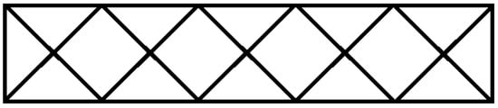
Scheme 1.
Envelope diagram for a Cu5X122− complex.
Quasi-planar oligomers are rarely isolated and usually aggregate into stacks in which neighboring oligomers are offset from one another so that halide ligands in one oligomer can form long, semicoordinate bonds to Cu2+ ions in the oligomer above or below. Thus some, and frequently all, Cu2+ ions in a quasi-planar oligomer have coordination numbers that can be characterized as 4 + 1, 4 + 2, or 4 + 1 + 1′, where the latter numbers express how many longer semicoordinate Cu-X bonds are formed in addition to the four shorter coordinate Cu-X (or –L) bonds (the last case refers to a situation in which one of two semicoordinate bonds is significantly longer than the other). Oligomers can stack in a variety of patterns with different amounts of translational offset from one another. To describe the variety of stacking patterns, Geiser and Willett, et al. [3] developed a notation, based on the envelope diagrams, of the form n(t∥,t⊥), where n is the nuclearity of the oligomer, t∥ is the distance the neighboring oligomer is translated (expressed as a multiple of the CuX4 square plane edge length) parallel to the long axis of the oligomer, and t⊥ is the similar translation perpendicular to the long axis of the oligomer. So, for example, the stacking pattern in (3-chloro-1-methylpyridinium)2Cu5Br12 (AKEJOQ) is 5(3/2,1/2) [4], as depicted by the envelope stacking diagram in Scheme 2.
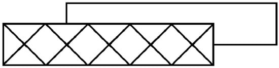
Scheme 2.
Envelope stacking diagram for 5(3/2,1/2) stacking.
For systems with more complicated stacking patterns, as many parenthetical translation pairs are appended as needed to describe the repeat unit of the stack. The envelope stacking patterns and notation are extensible to more challenging situations, such as compounds where neighboring oligomers within the stack are rotated by 90° relative to each other. In this case, a third element is included in parentheses to describe this rotation about the center of the oligomer, as exhibited by the envelope stacking pattern shown in Scheme 3, which is described by the notation 2(1,1,90°)(1,1,−90°)—a pattern found in (dimethylammonium)2Cu2Cl6 (CUMACL) [5].
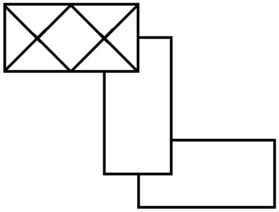
Scheme 3.
Envelope stacking diagram for 2(1,1,90°)(1,1,−90°) stacking.
A further extension of the notation is used when stacks overlap so that oligomers participate in more than one stack, such as found in (1,2-dimethylpyridinium)2Cu6Cl14 [6] (ZACSIF), whose envelope stacking pattern is shown in Scheme 4. Here, the stacking pattern symbol is derived by enclosing in square brackets the symbol for each stack in which the oligomer participates. Thus, for the stacking diagram in Scheme 4, the envelope stacking symbol is 6[(5/2,1/2)][−9/2,−1/2)]. Discrete oligomers are known for nuclearities up to n = 10 (found for (3,5-dibromopyridinium)2Cu10Br22 (UJODUS) with stacking pattern symbol 10[(7/2,1/2)][(−15/2,−1/2)] [7]). The longest planar, bibridged oligomers occur in the parent CuX2 compounds in which oligomers of arbitrary (essentially infinite) length are stacked to form layers with a pattern that, in principle, might be expressed by the symbol, ∝(m/2,1/2), where m is any integer.
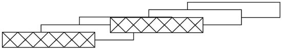
Scheme 4.
Envelope stacking diagram for 6[(5/2,1/2)][−9/2,−1/2)] stacking.
Oligomer stacks, in many cases, can be visualized as sections of the parent CuX2 layer structure with organic cations or neutral ligands terminating the infinite, planar oligomers of the parent [4]. Even exceptional cases such as the zig-zag stacks might be rationalized in terms of periodic stacking faults, while the overlapping stacks can be visualized as a group of parallel primary stacks joined together into a layer. A continuum of structure types is completed by “perforated” layer structures, exemplified by [(CH3)4P]Cu2Cl5 [8] (FAMYIB), in which dipositive CunX2n−22+ fragments are removed from the CuX2 layer with a pair of organic monocations placed on either side of the resulting hole. The further removal of dipositive fragments yields isolated oligomer stacks. In many cases, particularly with substituted pyridinium cations, the cations replace the fragments within the layer as end-to-end pairs between oligomers in neighboring stacks to replicate the structure of the parent CuX2 layer [4].
Nevertheless, the connection of oligomer stacking to the parent CuX2 layer structure and the corresponding stacking notation have proved durable concepts with an extensive literature. We present here the crystal structure of (1,2,3-trimethylpyridnium)2Cu5Br12, which presents a fresh challenge to these traditional notions.
2. Methods and Materials
2.1. Synthesis of (1,2,3-Trimethylpyridinium)2Cu5Br15
A total of 5.0 mL (0.43 mmol) of 2,3-dimethylpyridine was stirred with 3.5 mL of iodomethane and left in a covered beaker for 24 h. The resulting solid 1,2,3-trimethylpyridinium iodide was dissolved in water and stirred with a 20% molar excess of AgBr(s) for 24 h to effect halide replacement. The resulting AgX(s) was removed via vacuum filtration, 4.8 g of CuBr2(s) was dissolved in the resulting filtrate (to give a 1:2 ratio of organic cation to Cu2+), and the volume of the initial solution doubled with the addition of an equal volume of concentrated HBr(aq). This solution was left to evaporate slowly in a fume hood with dark purple crystals of the title compound forming after several weeks.
2.2. X-ray Crystal Structure Data Collection and Determination
General conditions and parameters of the data collection and structure determination are summarized in Table 1, with geometrical parameters for the anionic complex presented in Table 2. Low-angle reflections blocked by the beam catcher (as indicated by Fo << Fc.) were omitted

Table 1.
Experimental details.
Table 2.
Selected geometric parameters (Å, °).
Structure solution was resistant to direct methods or Patterson maps and was ultimately achieved by placing a copper atom at an inversion center for initial phasing with the identification of remaining atoms on subsequent electron density difference maps. The only H-atom visible on an electron density difference map was for the aromatic ring atom in the 5-position. The organic cation is two-fold disordered with the hetero ring atom disordered across the approximate mirror plane vertical to the cation ring. The disorder was modeled with two separate rings in which pairs of ring atoms on the two separate cations were constrained to the same refined positions and thermal parameters. Refined site occupation factors gave a value 0.56(3) for the major component. All non-H-atoms were refined anisotropically. H-atom positions were calculated to give an idealized geometry constrained to a riding model with C-H = 0.93 Å for aromatic and 0.96 Å for methyl group atoms. Even though the space is unambiguously determined by systematic absences, refinement of non-centrosymmetric models in monoclinic P21 or Pc space groups were conducted in an attempt to resolve the disorder. These gave structures in which anisotropic displacement parameters for most C and N atoms were non-positive definite, with no improvement in the agreement factors nor resolution of the placement of the disordered hetero ring atom.
3. Results
The structure contains quasi-planar, bibridged Cu5Br122- oligomers linked together in a two-dimensional layer network and 1,2,3-trimethylpyridinium cations sandwiched between these layers. An ORTEP diagram of the formula unit with labels for the symmetry unique oligomer atoms is presented in Figure 1. The oligomers have inversion symmetry about the central Cu2+ ion (Cu1) with planar (by symmetry) geometry for the coordinate Cu–Br bonds of Cu1. The other Cu2+ ions show a slight pyramidalization for their Cu–Br coordinate bonds which results from their forming only one semicoordinate bond to a bromide ion of a neighboring oligomer to give 4 + 1 coordination, in contrast to the 4 + 2 coordination of Cu1. Cu–Br bond lengths and Br–Cu–Br angles within the oligomer are unremarkable and conform to expected values [9], with a mean Cu–Br length of 2.42(2) Å and a slight reduction in internal Br–Cu–Br angles below the ideal value of 90° caused by mutual repulsion of neighboring Cu2+ ions that results in slight stretching of the oligomer along its long axis. An average Cu1–Br–Cu2 angle of 92.4(7)° and Cu2–Br–Cu3 of 93.8(3)° are close to the value where a crossover from ferromagnetic to antiferromagnetic coupling of the S = 1/2 centers within these oligomer systems is expected [10]; hence, it is difficult to predict the magnetic behavior of the oligomer.
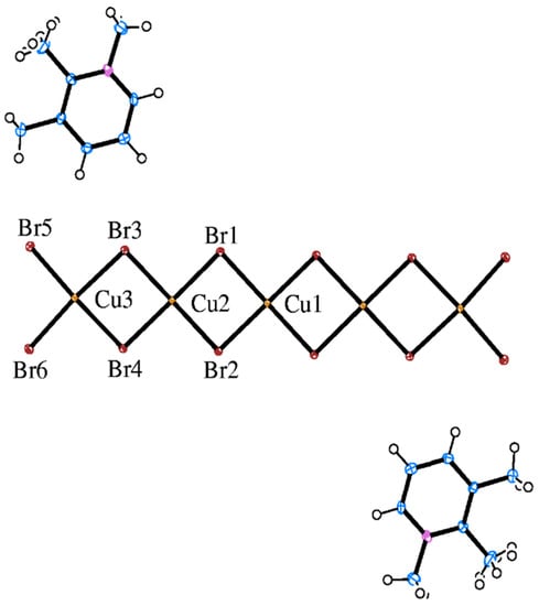
Figure 1.
ORTEP diagram (50% ellipsoids) of the formula unit of the (1,2,3-trimethylpyrindium)2Cu5Br12 structure with atom labels for the symmetry unique heavy atoms. H-atoms are drawn as spheres of arbitrary radii, and only one component of the disordered organic cation is shown.
The organic cation does not possess any formal site symmetry, although the gross shape of the cation is approximately C2v with the pseudosymmetry axis aligned with the bond between the C atoms of the middle methyl group and the aromatic ring. In a previous structure employing this cation, (1,2,3-trimethylpyridinium)CuCl3(H2O) [11], the organic cation did possess formal mirror plane site symmetry perpendicular to the cation plane that enforced two-fold disorder of the ring hetero atom. A similar disorder is found here, although not symmetry required, with the hetero atom found ~50% of the time on each side of the pseudomirror plane. In spite of the disorder, the organic cation geometry is unremarkable with aromatic C–C and C–N bond lengths ranging from 1.358(7)−1.385(7) Å, C– or N–C(sp3) bond lengths ranging from 1.500(7)−1.512(7) Å, aromatic ring angles ranging from 118.8(4)°–120.8(5)°, and C–(C or N)–C(sp3) angles ranging from 118.0(4)–121.1(5)°.
The pentacopper oligomer forms semicoordinate bonds to four neighboring complexes oriented at ~90° angles (more precisely, 91.04(3)° as measured by the angle formed between the least-squares line through Cu1, Cu2, and Cu3 on neighboring oligomers), depicted in the ball-and-stick diagram of Figure 2.
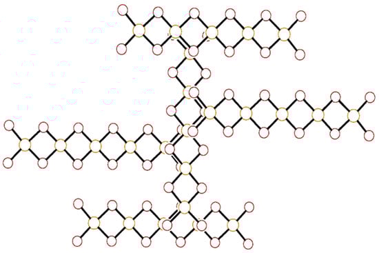
Figure 2.
Ball-and-stick diagram of a pentacopper complex aggregated through semicoordinate bond formation to four neighboring oligomers stacked above or below and rotated by 90°. All atoms are drawn as circles of arbitrary radii.
The longest semicoordinate bonds to bromide ions on neighboring oligomers are found for the central copper (Cu1-Bri = 3.2319(6) Å) with 4 + 2 coordination and are just short of the sum of the van der Waals radii (3.25 Å). The other semicoordinate bonds to the other Cu centers are shorter in length (Cu3–Br1ii = 2.9940(8) Å, Cu2–Br6i = 2.7322(8) Å) due to their 4 + 1 coordination. This arrangement leaves the oligomer with four fewer semicoordinate bonds than it would have when in a simple 5(1/2,1/2) stacking pattern in which every Cu center would form two semicoordinate bonds to neighbors. Since each of these four neighbors link and stack in turn with three additional oligomers, a two-dimensional cross-hatched layer network in (100) is rapidly built up, as shown in Figure 3.
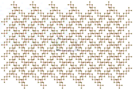
Figure 3.
Ball-and-stick plot of the cross-hatched, pentanuclear oligomer layer viewed perpendicular to (100) with b vertical and c horizontal.
The layer plot reveals an open layer framework completely unlike any oligomer stacking arrangement yet observed. The framework brings to mind “perforated” CuX2 structures, but this structure does not arise from excision of dipositive fragments to create holes in the layer. In fact, there is no connection between this layer structure and that of CuX2. In the latter structure, and its perforated analogs, the long axes of all quasi-planar oligomers are parallel. Here, long axes of neighboring oligomers are perpendicular to each other, and the regularly spaced rectangular voids established by groups of four oligomers are not holes in the layer (as is apparent in a space-filling plot) but depressions, much like the regularly spaced cups in an egg tray. The cups are filled by inversion-related cation pairs as the “eggs”, as shown in Figure 4.
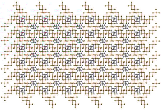
Figure 4.
Ball-and-stick plot of the cross-hatched oligomer layer in Figure 4, but now with inversion-related organic cation pairs nested into the depressions in the layer.
The inversion-related cation pairs also nest into depressions in the “egg tray” layer immediately above or below to complete the structure with cross-hatched oligomer layers stacked along a and related by an a-axis translation. The unit cell packing diagram in Figure 5 presents a different view edge onto the oligomers of the layer and shows that the planar organic cations are nearly coplanar with the oligomer planes (3.42(1)° angle between mean plane normals).
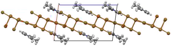
Figure 5.
Ball-and-stick unit cell packing diagram for (1,2,3-trimethylpyridinium)2Cu5Br12 viewed parallel to b with a almost vertical and c horizontal. Atoms are drawn as spheres of arbitrary radii and H-atoms are included to identify placement of methyl groups. The mixed organic cation/complex anion sheets coincident with (30) are edge-on in this diagram.
The oligomers and organic cations are neatly arranged into sheets coincident with (30) and are viewed edge-on in Figure 5. These mixed oligomer/organic cation sheets consist of zipper-like ribbons made up of two rows of organic cations staggered with respect to one another and with methyl groups directed to the center line of the ribbon. Between the sheets are rows of oligomers, with the long axis of the oligomer tilted with respect to the row axis (~45°) to produce a herringbone pattern for oligomers in neighboring rows, as shown in Figure 6. Neighboring oligomers in a row of the sheet are related by a b-axis translation, while the center axis of the organic cation ribbon corresponds to the 21 screw axis.
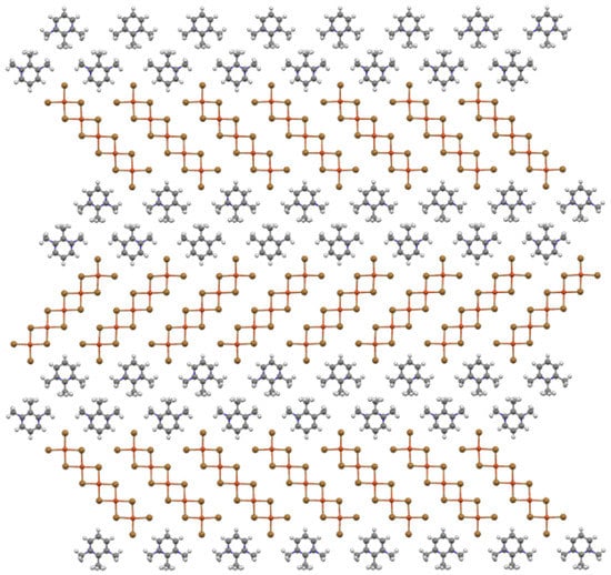
Figure 6.
Ball-and-stick diagram of the mixed cation/oligomer sheets viewed perpendicular to the (30) plane with b horizontal.
This packing arrangement is similar to that found in the structures of (1,2,3-trimethylpyridinium)CuCl3(H2O) [11] and (1,2,6–trimethylpyridinium)2CuX4 [12]. These structures are also are built up from sheets of zipper-like ribbons of organic cations separating rows of halocuprate(II) complexes with the stacking of these sheets generating the full structure. The title structure can also be visualized as stacking mixed cation/complex anion sheets atop one another so that oligomers in rows with one tilt axis direction stack atop oligomers in rows with the other tilt direction to produce the cross-hatched layers as shown in Figure 7.
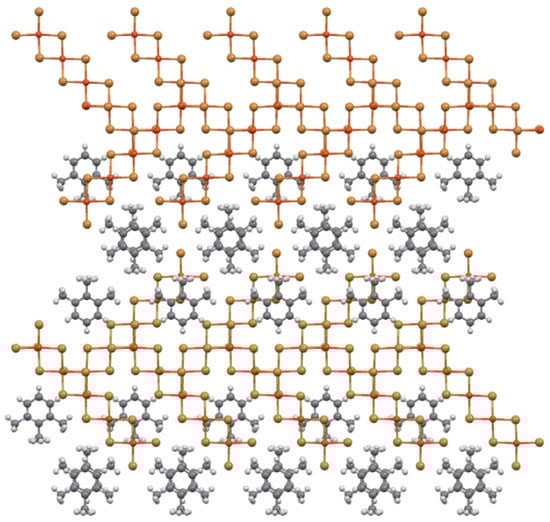
Figure 7.
Ball-and-stick diagram of two mixed organic cation/oligomer sheets stacked together and viewed perpendicular to the (30) plane.
Each oligomer in the layer above in Figure 7 overlaps, and forms semicoordinate bonds to, two oligomers in the layer below. Thus, when the stacking is repeated with a third sheet, each oligomer in the second sheet would now have their full complement of four neighbors. The stacking of the second sheet also starts formation of the inversion-related organic cation pair “eggs” that are found between cross-hatched layers.
4. Discussion
A portion of the envelope stacking diagram for the title compound depicted in Scheme 5 presents some ambiguity in determining a useful stacking pattern symbol. Considering the grey envelope as a starting point: it has four neighbors, two forming semicoordinate bonds below and two above. One can combine the notations use for the zig-zag stacks and the overlapping stacks here by considering the grey envelope as participating in two stacks—each with a two oligomer repeat, This could lead to a stacking pattern of 5[(1/2,5/2,90°)(1/2,5/2,−90°)][(5/2,1/2, 90°)(5/2,1/2,−90°)] or 5[(1/2,5/2,90°)(5/2,1/2,−90°)][(5/2,1/2, 90°)(1/2,5/2,−90°)] depending on which pair of upper and lower neighbors one wishes to use. We question, at this point, if the stacking pattern symbology is too unwieldy to effectively communicate more complicated oligomer stacking, especially in a case such as this where oligomer stacking is in no sense a reduction in the parent CuX2 structure.
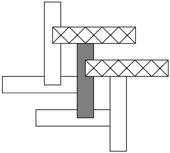
Scheme 5.
Envelope stacking diagram for the title compound.
Rather than pursue questions of individual oligomer stacking, we propose to examine this, and other structures, from a different perspective: namely in terms of stacking of mixed cation/oligomer sheets. Such an approach is certainly not new, and has long been used for compounds, such as the ABX3 perovskites in which variation of stacking sequence of the mixed cation/anion AX3 sheets leads to a wide variety of compounds with differing connectivity between coordination polyhedral [13]. ABAB… stacking of hcp AX3 layers leads to chains face-sharing of BX6 octahedra in the hexagonal perovskite structure, whereas ABCABC… stacking leads to a network of corner-sharing BX6 octahedra in the cubic perovskite structure. More complicated stacking sequences lead to structures containing both face-sharing and corner-sharing BX6 octahedra. Our approach is not meant to replace the well-established envelope stacking diagrams and symbology, which have been very successful to date, but to complement them. Indeed, this approach requires that all oligomers in the structure be reasonably coplanar, which is not always the case.
The application of this sheet stacking principle to the structure of the title compound reveals an alternative structure. Rather than stacking the second sheet so that oligomers with the perpendicular orientation are placed above, e.g., …ABAB… type stacking, oligomers of the same orientation can be stacked above, e.g., …AAAA… stacking, to yield in all cases quite reasonable (and conventional) isolated 5(5/2,1/2) stacks of pentacopper complexes as shown in Figure 8. This stacking also leads to the formation of the same type of inversion-related organic cation pairs as found in the cross-hatched structure, but now they serve to isolate the stacks into layers. These oligomer stacks are still four semicoordinate bonds short of full semicoordination, as is the case for the crosshatched layer structure, so there is no benefit achieved in the alternate stacking from the standpoint of improved bonding. At the same time, anionic stacks within the same layer are placed closely together, leading to increased electrostatic repulsion, a factor that might explain why the cross-hatched layer structure is preferred over the conventional oligomer stack.
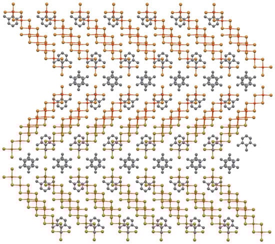
Figure 8.
Ball-and-stick diagram of alternate stacking of two mixed organic cation/oligomer sheets from the title structure with neighboring oligomers now parallel to one another to yield isolate 5(5/2,1/2 stacks) with “inversion-related” organic cation pairs separating layers of stacks.
A triclinic unit cell can be derived for this stacking by taking the repeat vectors along each of the two stacks of differing orientation (9.578 Å) and doubling the a-axis to account for the fact that layers of oligomer stacks of the same orientation are now twice as far apart as neighboring layers in the cross-hatched structure. This unit cell has the same volume as that of the title compound but transforms to a C-centered monoclinic cell (a = 16.3327 Å, b = 10.0115 Å, c = 20.1452 Å, and β = 82.34°). A visualization of this structure in space group C2, with appropriate transformation of atomic coordinates from the title structure, gives quite reasonable ORTEP and unit cell packing diagrams (Figure 9). More complicated stacking sequences than these could also be envisioned.
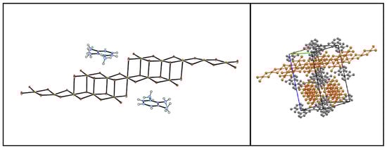
Figure 9.
Diptych depicting the ORTEP diagram (50% ellipsoids) for the hypothetical structure obtained by …AAAA… stacking of mixed organic cation/oligomer sheets (left) and the unit cell packing diagram (right) viewed along (110) (in the transformed unit cell) down one oligomer stack orientation with the other stack orientation along (10). The stacks are arranged into layers along (002) separated by organic cation pairs.
Extending this analysis to the hexacopper oligomer system in (1,2-dimethylpyridinium)2Cu6Cl14, whose overlapping stacking pattern is shown in Scheme 3, provides a new view of structure formation. All oligomers in this system are found in sheets coplanar with (230) (although organic cations are not coplanar with the oligomers in this case). The oligomer sheets contain lines of parallel oligomers, as shown in Figure 10, so the cross-hatching observed in the title structure is not possible through the stacking of these sheets. Oligomers in the next sheet that stacks above must, except in one case, bridge two oligomers below due to the length of the oligomers—thus giving rise to the overlapping stacks (the one case where this would not happen would be with a 6(1/2,1/2) stacking pattern). The type of overlapping pattern observed likely results from the packing requirements of the tilted organic cations, which form inversion-related pairs (as in the title structure).
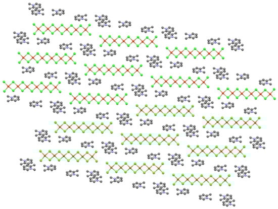
Figure 10.
View of the mixed organic cation/oligomer sheet in (1,2-dimethylpyridinium)2Cu6Cl14 (ZACSIF) viewed perpendicular to the (230) plane.
Likewise, the oligomers of (3-chloro-1-methylpyridnium)2Cu5Br12, whose stacking pattern is shown in Scheme 2, are all coplanar with each other and the organic cations in a sheet parallel to (103) as shown in Figure 11. In this case, the oligomers take two different orientations that are markedly oblique, neither parallel nor perpendicular. Thus, a cross-hatched pattern is not possible, since there are no perpendicular oligomers, and the oblique angle forces the sheet above to stack so that oligomers of the same orientation stack atop each other—leading to the observed 5(3/2,1/2) stacks. While individual oligomer stacks in this structure are derived from the parent CuX2 structure, there is no broader connection, i.e., removal of CunX2n−22− fragments. Instead, the organic cations force the oblique packing of oligomers in the sheet to accommodate specific C–Cl⋯Br interactions to a terminal ligand within the sheet.
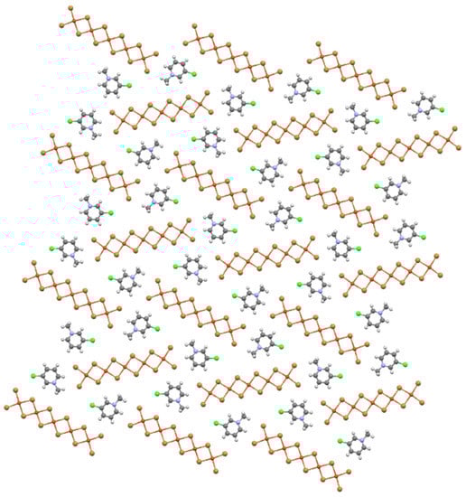
Figure 11.
Ball-and-stick diagram of the mixed organic cation/oligomer sheet in (3-chloro-1-methylpyridinium)2Cu5Br12 (AKEJOQ) viewed perpendicular to the (103) plane.
5. Conclusions
Quasi-planar halidocuprate(II) oligomers stack together in a wide variety of patterns, which in the past have been described through a notation that focuses solely on the inorganic structure. Differences in stacking patterns have been vaguely attributed to “packing forces” with phenomenological models invoked to justify particular stacking patterns [14]. These treatments arose in an era in which computer visualization of structure packing was rudimentary. Modern visualization software easily renders extended packing for examination to determine if mixed cation/anion sheets are present to build up the extended structure. The identification of these sheets provides greater insight into the cation–anion interactions and arrangements that dictate a particular stacking pattern while also allowing the exploration of alternative patterns and structures. Finally, as is demonstrated by the title compound, the stacking of mixed cation/anion sheets may provide a better description of oligomer stacking than traditional methods.
Author Contributions
Conceptualization, M.R.B.; methodology, M.R.B.; formal analysis, M.R.B. and S.A.; investigation, S.A.; data curation, M.R.B.; writing—original draft preparation. M.R.B.; writing—review and editing, M.R.B.; visualization, M.R.B.; supervision, M.R.B.; project administration, M.R.B. All authors have read and agreed to the published version of the manuscript.
Funding
This research received no external funding.
Informed Consent Statement
Not applicable.
Data Availability Statement
Crystallographic data have been deposited with the Cambridge Crystallographic center, deposition number 2201425.
Acknowledgments
The authors wish to thank the National Science Foundation DUE CCLI-A&I program (grant # 9951348) and Southeast Missouri State University for funding the X-ray diffraction facility.
Conflicts of Interest
The authors declare no conflict of interest.
References
- Willett, R.D.; Dwiggins, C., Jr.; Kruh, R.F.; Rundle, R.E. Crystal Structures of KCuCl3 and NH4CuCl3. J. Chem. Phys. 1963, 38, 2429–2436. [Google Scholar] [CrossRef]
- Willett, R.D.; Rundle, R.E. Crystal Structure of Cu2Cl4(CH3CN)2, Cu3Cl6(CH3CN)2, and Cu5Cl10(C3H7OH)2. J. Chem. Phys. 1964, 40, 838–847. [Google Scholar] [CrossRef]
- Geiser, U.; Willett, R.D.; Lindbeck, M.; Emerson, K. Crystal structure of bis (trimethylammonium) decabromotetracuprate (II): A review of stacking patterns in pseudoplanar CunX2n+22− and CunX2nL2 oligomers. J. Am. Chem. Soc. 1986, 108, 1173–1179. [Google Scholar] [CrossRef]
- Kelley, A.; Akkina, S.; Devarapally, G.K.; Nalla, S.; Pasam, D.; Madhabushi, S.; Bond, M.R. Nine compounds containing high-nuclearity [CunX2n+2]2− (n = 4, 5 or 7; X = Cl or Br) quasi-planar oligomers. Acta Crystallogr. 2011, 67, m22–m34. [Google Scholar] [CrossRef] [PubMed]
- Willett, R.D. Crystal Structure and Optical Properties of (CH3)2NH2CuCl3. J. Chem. Phys. 1966, 44, 39–43. [Google Scholar] [CrossRef]
- Bond, M.R.; Place, H.; Wang, Z.; Willett, R.D.; Liu, Y.; Grigereit, T.E.; Drumheller, J.E.; Tuthill, G.F. Structures and Magnetic Susceptibility Studies of Four New High-Nuclearity Copper (II) Halide Oligomers. Inorg. Chem. 1995, 34, 3134–3141. [Google Scholar] [CrossRef]
- Haddad, S.; Awwadi, F.; Willett, R.D. The Aryl Bromine−Halide Ion Synthon and Its Role in the Control of the Crystal Structures of Tetrahalocuprate (II) Ions. Cryst. Growth Des. 2003, 3, 301–311. [Google Scholar]
- Haije, W.G.; Dobbelaar, J.A.L.; Maaskant, W.J.A. The structure of tetramethylphosphonium dicopper pentachloride. Acta Cryst. 1986, 42, 1485–1487. [Google Scholar] [CrossRef]
- Willett, R.D. Structural correlations in pseudo-planar bibridged CunCl2nL2 oligomers. Acta Cryst. 1988, 44, 503–508. [Google Scholar] [CrossRef]
- Fletcher, R.; Hansen, J.J.; Livermore, J.; Willett, R.D. Crystal structure and magnetic properties of [(C2H5)2NH2]2(Cu3Br8).CuBr2.C2H5OH: Magnetostructural correlations in copper (II) bromide salts. Inorg. Chem. 1983, 22, 330–334. [Google Scholar] [CrossRef]
- Nalla, S.; Bond, M.R. [CuCl3(H2O)]− complexes aggregated to form hydrate columns in methyl-substituted pyridinium or piperidinium salts. Acta Cryst. 2011, 67, m185–m194. [Google Scholar] [CrossRef] [PubMed]
- Kelley, A.; Nalla, S.; Bond, M.R. The square-planar to flattened-tetrahedral CuX42− (X = Cl, Br) structural phase transition in 1,2,6-trimethylpyridinium salts. Acta Cryst. 2015, 71, 48–60. [Google Scholar]
- Plumer, M.L.; Hood, K.; Caille, A. An Ising-like model of stacking-sequence polytypism in ABX3 compounds. J. Phys. C 1988, 21, 4189–4206. [Google Scholar] [CrossRef]
- Willett, R.D.; Bond, M.R.; Pon, G. Theoretical predictions and new structures of stacking patterns for CunX2nL2 oligomers. Inorg. Chem. 1990, 29, 4160–4162. [Google Scholar] [CrossRef]
Publisher’s Note: MDPI stays neutral with regard to jurisdictional claims in published maps and institutional affiliations. |
© 2022 by the authors. Licensee MDPI, Basel, Switzerland. This article is an open access article distributed under the terms and conditions of the Creative Commons Attribution (CC BY) license (https://creativecommons.org/licenses/by/4.0/).