Review

Photosensitive Alignment: Advanced Electronic Paper-Based Devices

by
Vladimir Chigrinov
1,2,3,4,
Aleksey Kudreyko
5,* and
Jiatong Sun
6
1
Department of Electronic and Computer Engineering, Hong Kong University of Science and Technology, Clear Water Bay, Kowloon, Hong Kong, China
2
Department of Theoretical Physics, Moscow Region State University, 141014 Mytishi, Russia
3
Laboratory of Molecular Electronics, South Ural State University, 454080 Chelyabinsk, Russia
4
Research Center for Experimental and Theoretical Physics, Chemistry and Space Sciences, Genius Development and Science Tech Future Co., Ltd., Hong Kong, China
5
Department of Medical Physics and Informatics, Bashkir State Medical University, 450008 Ufa, Russia
6
College of Information Science and Technology, Donghua University, Shanghai 201620, China
*
Author to whom correspondence should be addressed.
Crystals 2022, 12(3), 364; https://doi.org/10.3390/cryst12030364
Submission received: 17 February 2022 / Revised: 5 March 2022 / Accepted: 6 March 2022 / Published: 9 March 2022

Abstract

:
In this review we describe the reversible photoalignment effect imposed on the director in nematic liquid crystals that provides an approach for fabrication of advanced optically addressed devices. Several new concepts have been developed to render photosensitive materials during the past decade. Functional soft azo dye compounds exhibiting distinct functionalities in response to polarized light are highly desirable for fabrication of optically rewritable electronic paper. An optically rewritable element base using simple and inexpensive materials can potentially enable the development of novel environmentally friendly, paper-like gadgets with improved functionality over regular electronic paper. We argue that an optically rewritable technique is relevant for some applications, where conventional paper might be irrelevant. In particular, we have tested and discussed several techniques of color and 3D image formation. This strategy for fabrication of novel devices offers versatile methods for visualization. We also show that the intensity modulation of the irradiation light has a potential to generate improved grayscale visualization. This principle is based on the statistical distribution control of photosensitive azo dye molecules, driven by the incident polarized light. Additionally, we discuss the functional characteristics of the developed prototypes.

1. Introduction

First attempts in reading and writing the effects of liquid crystal displays assumed electric-field-induced reorientation of director for image formation (e.g., [1,2]). Further development of liquid crystal systems has divided displays for reflective modes. Typical transmissive displays are used in the devices, where a backlight is required to display the content on the screen. Reflective displays show the designed information by manipulating the intensity of the reflected ambient light through microfluidic behavior in pixels driven by electrophoresis, electrowetting or electromechanical forces. Such displays are used in electronic papers, security films, calculators and other devices.
Today, when most people think about electronic paper, they consider products containing electrophoretic display technology, which is known as E-Ink [3]. However, many other electronic paper techniques have been developed decades after E-Ink [3,4]. The optically rewritable technique is one of them and is distinctive among these techniques because it does not require electrodes and has numerous other applications in photonics [5,6]. Thus, optically rewritable electronic paper (ORW e-paper) is an electrode-free and optically addressed device with a grayscale capability, wide viewing angles and a contrast ratio of about 10:1. All these properties have been widely discussed in our previous reviews [7,8] and studies [9,10]. Further investigation of ORW e-paper has shown that it can play the role as an element base for advanced light-driven applications, which include security films [11], methods of 3D visualization [12,13], color reflectors [14] and transparent devices [15].
In comparison with the conventional liquid crystal (LC) displays, the present full-color ORW technique cannot achieve satisfactory color reproduction. The reason is that filters are highly efficient blockers of light at wavelengths below and higher than the transition window. Consequently, the contrast ratio cannot be high. Another issue with the ORW technique is the fact that it only produces 5-bit grayscale [16]. The main reason of this limited performance is a steep dependence on azimuthal anchoring energy versus the irradiation dose [17,18]. According to the rotational diffusion theory [19], the saturation level of the relative order parameter depends on the exposure intensity. We suppose that exposing the photosensitive substrate with slowly increasing intensity results in a steep decrease in the azimuthal anchoring energy-irradiation dose curve. Consequently, the possibility of continuous grayscale modulation becomes more feasible. Such a mechanism for grayscale formation is discussed in this study.
Although the ORW technique for e-paper is quite mature, it does not always produce the desired physical characteristics for colored images. In this review, we present a deeper discussion of the fundamental operating issues of color ORW e-paper and visualization of 3D images. Our discussion is based on the assembled original prototypes as well as other comprehensive studies. These e-paper based systems and technologies might move closer to several aspects of new gadgets.
In addition to ORW technology for colored e-paper, electrophoretic technique [20] is also promising for e-paper devices. In this case, each pixel is filled by two particles in capsules: one contains yellow and cyan, the other one contains magenta and black. By controlling voltages, the colored particles either spread across the pixel or move out of sight altogether, making it possible to render different colors by controlling the number of colored particles shown [21]. However, this technique is totally ambient light adaptive [22] because the database that stores tone-mapping curves for different ambient lights must be developed. Thus, a competing technique also shares image quality problems. Other known techniques, which include electrowetting, liquid power, cholesteric LC etc. [23] require voltage to keep the state of the pixel. As the future of ORW e-paper continues to evolve, the functionality of such devices is also extending, and will be discussed in this review. We also address the advantages and liabilities of various advanced e-paper based devices.
This review is organized in the following manner. The introductory section aims to introduce readers to the current problems of e-paper based devices. A theoretical examination of the possibility to improve grayscale performance is discussed in Section 2. Then, we discuss applications of e-paper for security films (Section 3). In Section 4 we discuss the fabrication technique of colored ORW e-paper device. In Section 5 we show two perspective techniques of 3D ORW e-paper.

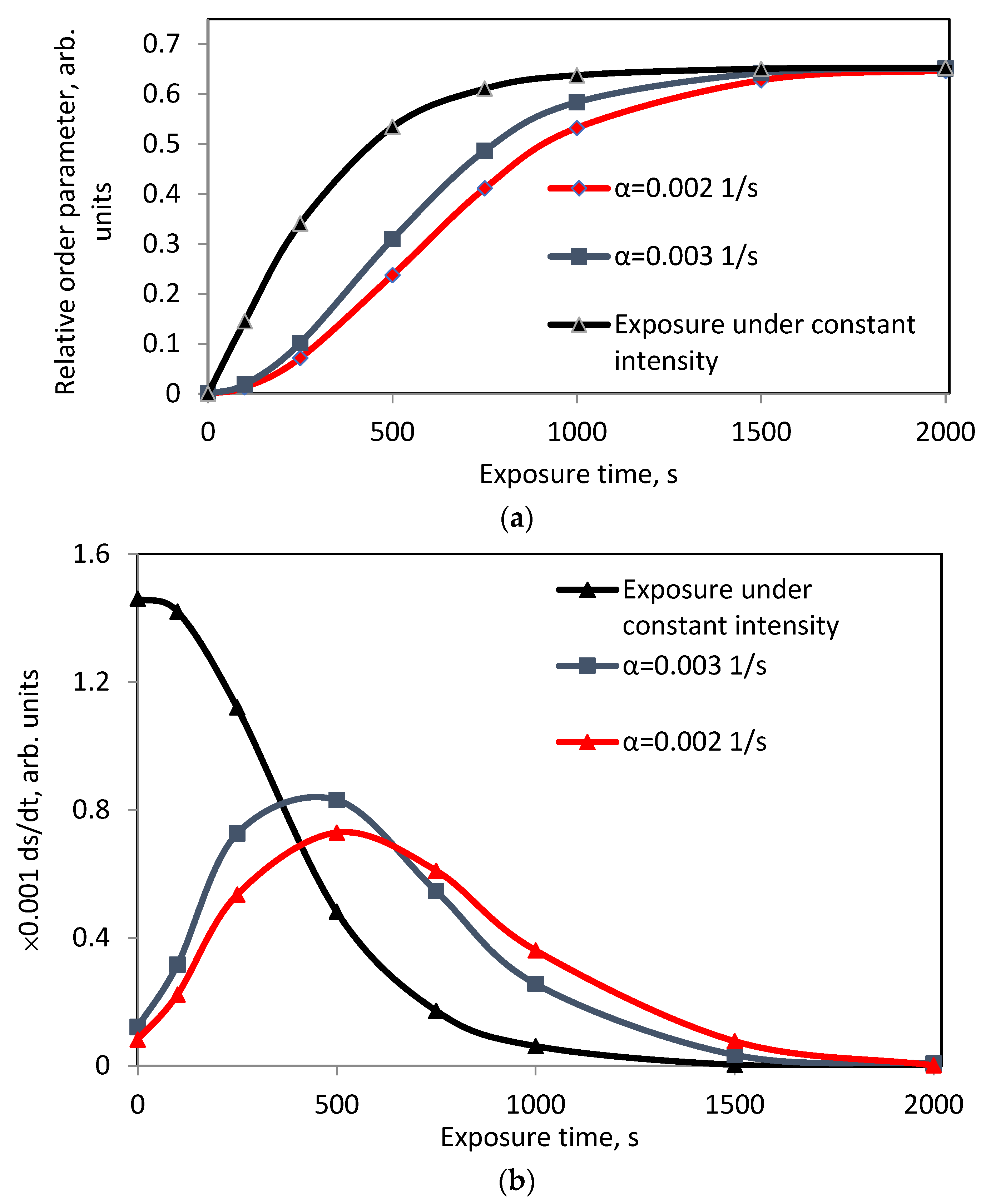
2. Adaptive Model for Extended Grayscale Performance
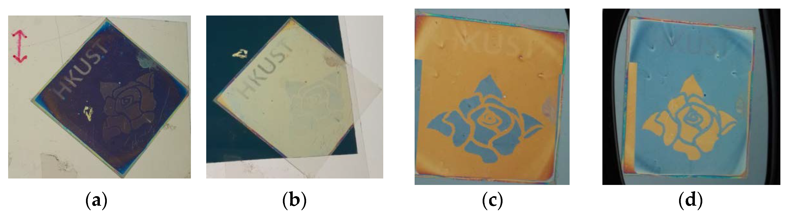
Extended grayscale performance presents the largest R&D challenge for ORW e-paper technology. In the scope of this review, it is impossible to discuss improved grayscale without considering orientational ordering of azo dye molecules, which governs the twisted structure of the nematic LC. Consequently, it is appropriate to recall that the constant light intensity exposure to optically sensitive substrate results in a rapid increase in the relative order parameter of azo dye molecules [5]. This effect triggers limited performance of gray scale images.
To achieve a compromised grayscale performance, different shapes of the optical signal were treated [10]. However, the kinetics of the relative order parameter (s) do not depend on the shape of the optical signal if its mean intensity is a constant value. Further investigation shows that the exposure of optically sensitive surface with a modulated light intensity is promising for achieving our goal. Referring to the rotational diffusion model [19] imposed on the probability density function f ( θ , t ) , one can calculate the kinetics of the order parameter:
2 f θ 2 ( A 2 + 3 2 a k T P 2 ) θ [ f sin 2 θ ] = 1 D f t P 2 = 0 π P 2 ( θ ) f ( θ , t ) sin θ d θ / 0 π f ( θ , t ) sin θ d θ , P 2 ( θ ) = 1 2 ( 3 cos 2 θ 1 ) ,
where k is Boltzmann’s constant; T is the absolute temperature, a is the temperature-dependent coefficient, associated with intermolecular interactions; D is the rotational diffusion coefficient; S = P 2 is the order parameter and A is the dimensionless parameter, which is proportional to the light intensity. The quantity of the order parameter in relative units (s = S/Smax) is more relevant for further analysis. This parameter defines a simple measure of the axial orientational order of uniaxial azo dye molecules, that is s = 0 in the case of isotropic distribution, and s = 1 for perfect orientational ordering.
Some further clarifications are provided. Let the alignment layer be exposed by a modulated intensity, which is set by an observer. In the following simulations, we use three optical signals, indicating constant light exposure and an increase in exposure intensity. Let the optical signals have an ideal constant intensity A = A0 and a gradual increase in intensity, e.g., A = A 0 ( 1 e α t ) , where α is a non-zero constant. Once the numerical values of f ( θ , t ) are known, we can calculate the kinetics of the relative order parameter with the proper boundary conditions [10].
The simulation results show that the increased rate of the relative order parameter depends on two main factors. One is the local average of the optical signal (see Figure 1a), another is the rate of change of the intensity value. A simple computation of the derivative ds/dt shows that the relative order parameter during constant intensity exposure achieves its saturation level prior to the intensity modulated exposure (see Figure 1b). Meanwhile, the modulated exposure intensity leads to less steep increase rate of the azo dye orientational ordering.
Thus, a simple investigation of the rotational diffusion theory shows that the modulated intensity increase results in the modulated growth of the relative order parameter. This understanding of the relative order parameter response to the modulated light is critical for the ability to obtain enhanced grayscale images on ORW e-paper.

3. Security Films

Passive protection of information and equipment performance can be realized by security film. Reflective optical security films have a potential to provide a wide range of applications for government services and various industries. Numerous technologies are vying for reflective applications, e.g., patterned fluorescent polymer compounds were used for the fabrication of security films [24]. For example, the mechanical stress of thermoplastic polyester-based security film transfers the strains of its surface to the coating. The latter is observed as interference fringes [25]. Potential applications of security films are not limited to information display. Many studies have a rising interest to mechanofluorochromic materials, which are promising as optical materials for applications in mechanosensors, security films and optoelectronic devices [26].
The approach we discuss below is based on electrode-free ORW e-paper technique [11], which is used to fabricate a quick response code (QR code). At first, a transparent film must be coated by photosensitive azo dye (sulphonic dye, SD1) layer. Another substrate is optically passive. The coating technique and rubbing processes are reported in a study [27]. Then, liquid crystal polymer UCL-017 was used as the solvent with the reflective polarizer film under the cell. The birefringence coefficient of the LC compound is Δn = 0.2 before polymerization and Δn = 0.17 after the polymerization [28]. The thickness of the LC polymer was controlled by varying the spin coating speed and polymer concentration. Then the cell must be exposed through a patterned photomask with the resolution of 100 µm. Note that the resolution of this technology is 2 µm. In other words, a much higher resolution is supported by the ORW technique. This statement is important because the high resolution of the transparent film is responsible for the grayscale performance.
Figure 2 demonstrates the application of the fabricated security film for QR codes. After placing a linear polarizer, the image of a QR code appears, and it can be scanned by a smartphone.
In practice, any image on previously discussed security film can be visualized by a 90° rotation of the polarizer. Advanced optical security films, based on the polarization state, represent another class of promising devices. In order to fabricate a complex security film, the photosensitive surface was exposed by the light of different polarizations: 0°, 45° and 90°. Initially, the glass plate was exposed through a single polarizer. Then, the polarization plane was rotated by 45°, and the surface was exposed again through a “HKUST” photomask and a phase plate. On the next step, the polarization plane was rotated by 90°, and the pattern of “flower” was exposed through another phase plate. These manipulations enable us to observe four different states of the image, where two of the states are observed through a linear polarizer, whereas two other images are observed through a circular polarizer. When a glass plate is spun three times at 2500 rpm for 25 min, it is called a mixing process. This LC is not simply a wave plate, but it becomes more complex optical device. Our observation of the word “HKUST” through a linear polarizer is depicted in Figure 3a,b.
In order to visualize the image, a pair of 3D glasses is needed, where the lenses are circular polarizers. One can observe pale orange as the background color, a flower of pale blue color (Figure 3c) and vice versa when the polarizer is flipped (see Figure 3d).
Thus far, we have discussed the positive benefits and potentials of complex security films with alternative states of visualization. The security level can be higher if different polarizers are used to observe the various states of the recorded pattern. The feasibility of printing secure optically rewritable QR codes on flexible LC cells can represent another solution for protecting personal data. Complex security films provide higher security level because the images are latent, and different polarizers are needed for the visualization.

4. Color ORW e-Paper

Recent achievements in nanofabrication have opened an efficient way to control light properties at a subwavelength scale. For example, surface plasmon-based nanostructures are attractive due to their small dimensions and their ability for efficient light manipulation, which can find applications in color e-paper [29]. From such an approach arises the solution of several problems: optical performance, color purity and an efficient nanofabrication method to produce a cheap device. Other color versions of e-paper [30,31] are also less common due to the considerable loss in absolute reflectivity and the technical challenges when introducing three-color subpixels.
Despite all the issues with other approaches, the discussed ORW technique does not assume complex technical solutions in microfabrication. Below, we demonstrate the technical details of ORW color e-paper.
The dose of the exposure energy results in the corresponding azimuthal anchoring energy and the LC twist angle, which is visualized in the crossed polarizer (P) and analyzer (A) as the change of the transmitted light intensity (Figure 4a). The idea behind color formation in e-paper display is based on the use of either filters or reflective paint for the transmitted or reflective light beam (Figure 4b). We note that the result of Section 2 is relevant to generate extended intensity levels in color ORW e-paper.
Using the former technique, we assembled colored ORW e-paper, which works in a similar way as ordinary liquid crystal display. Such displays with the backlight unit can generate combinations of primary colors (red, green and blue) when the incident light goes through the twisted structure of a nematic LC (see Figure 5). The twisted structure of the nematic LC can be adjusted in such a way that the normalized light intensity transmitted through a single-color filter varies between 0 and 1. However, the idea of ORW e-paper does not assume a backlight source. Accordingly, filters play the role of intensity modulators in e-paper displays. A feature of this approach is that photoalignment enables accurate alignment of the patterned mask.
Further applicability of the discussed methodology was tested on the prototype of color ORW e-paper. The corresponding colored image is depicted in Figure 6a. To gain further insight into performance of the photoaligned color e-paper, we have replaced the color array (see Figure 5) with a reflective paint coating. Consequently, we observe the image in the reflective mode (see Figure 6b). No additional reflectors are required. However, both the colored filter and reflective paint have a high absorption of light, which results in a decreased contrast and brightness.
The methods of generating color levels by polarization rotation have been discussed. Flexible-spacer method [32] is able to provide colored images; however, this approach has poor color performance.

5. 3D Visualization

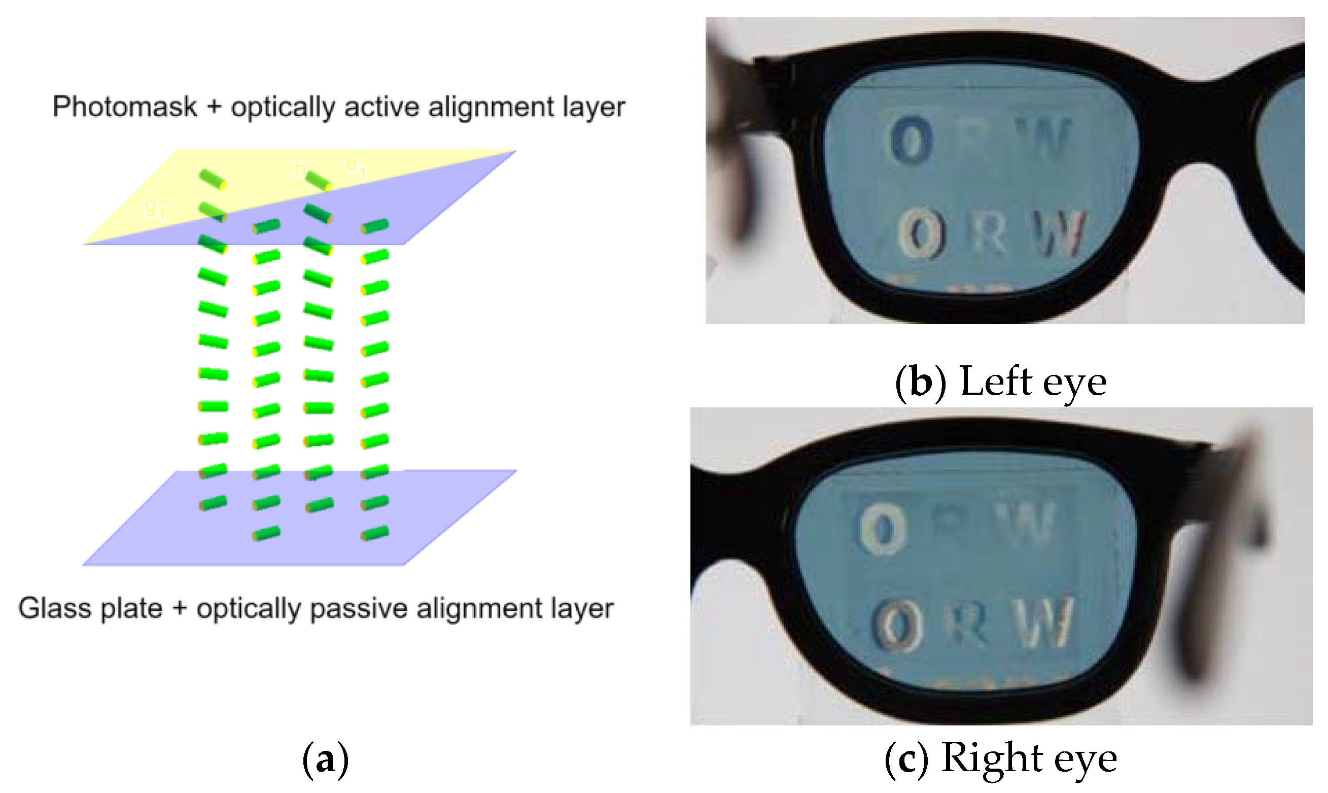
5.1. Stereoscopic ORW e-Paper

The 3D application of reversible polarization of liquid crystals was introduced by L. Lipton, who utilized the high-speed electric-field-modulation of liquid crystals to create flicker-free 3D computer displays [33]. Other known techniques use a holographic beam splitter applied to an autostereoscopic polymer dispersed LC display [34]. Meanwhile, to the best of the authors’ knowledge, the ORW technique is the only known approach for the fabrication of electrode-free 3D images on e-paper. Below, we consider the methods of image formation.
The idea of stereoscopic effect is based on generation of opposite handed circular polarizations [35]. Two-domain patterned retarders are often used in stereoscopic 3D displays. The stereoscopic ORW cell consists of two substrates, covered by optically passive and optically active layers (see Figure 7a). In order to generate the 3D image on the ORW LC panel, three alignment domains with the twist angles of +45°, −45° and 0° with respect to the easy axis of the optically passive alignment layer, were created. The light which falls on these domains is followed by a quarter-wave plate that becomes right-handed circularly polarized and left-handed circularly polarized, and can be discriminated by polarizing glasses.
The methodology for the generation of 3D image is as follows: the whole panel must be divided into three alignment domains with the twist angle of 0° and ±45° with respect to the easy axis of the optically passive alignment layer, respectively. Then, a quarter-wave plate with the optical axis parallel to the easy axis (0°) must be placed on the top of the ORW panel. Due to the waveguide mode, the transmitted light from the cell follows the twist of the easy axis on the top layer. The difference between the left and right images enables the depth adjustment of the 3D image. This shows that the two photoaligned areas of the nematic cell with the twist angles of ±45° are visualized with the polarizers for left and right eyes. The domain with the twist angle of 0° is visible for both eyes. Note that polarizers with high and fairly uniform transmittance spectra allow us to obtain the image with relatively high contrast [10]. Theoretical discussions of stereoscopic e-paper based devices may be found in the study [13].
Following this concept, a 3D image was recorded on ORW e-paper, (see Figure 7b,c). Then, our perception system combines the input images in 3D space.
An important issue for 3D images is crosstalk. This issue depends on many complex interactions, viz. how well the image is separated, how well it is restricted, quality of the amplitude mask and polarizers. Anchoring energy and the cell gap are also crucial parameters determining the crosstalk effect.
One effect of crosstalk is the presence of ghosting—or a slight double image—within the 3D image viewed on the display. The perception of ghosting may increase due to locally higher contrast within a given image combined with increasing screen disparity. In order to minimize the crosstalk, several periodic masks with different periods have been studied and we found that the mask with the periodicity of 100 μm provides optimal quality with a crosstalk of less than 6.5%. For the photomasks of smaller periods, the optical quality decreases due to several limitations, which are related to the anchoring energy, alignment layer, diffraction, dispersion etc. The disclination line between the two domains is another issue of the crosstalk effect. For the chosen conditions and the alignment layer, it is restricted to 10 μm, which is beyond human eye perception.

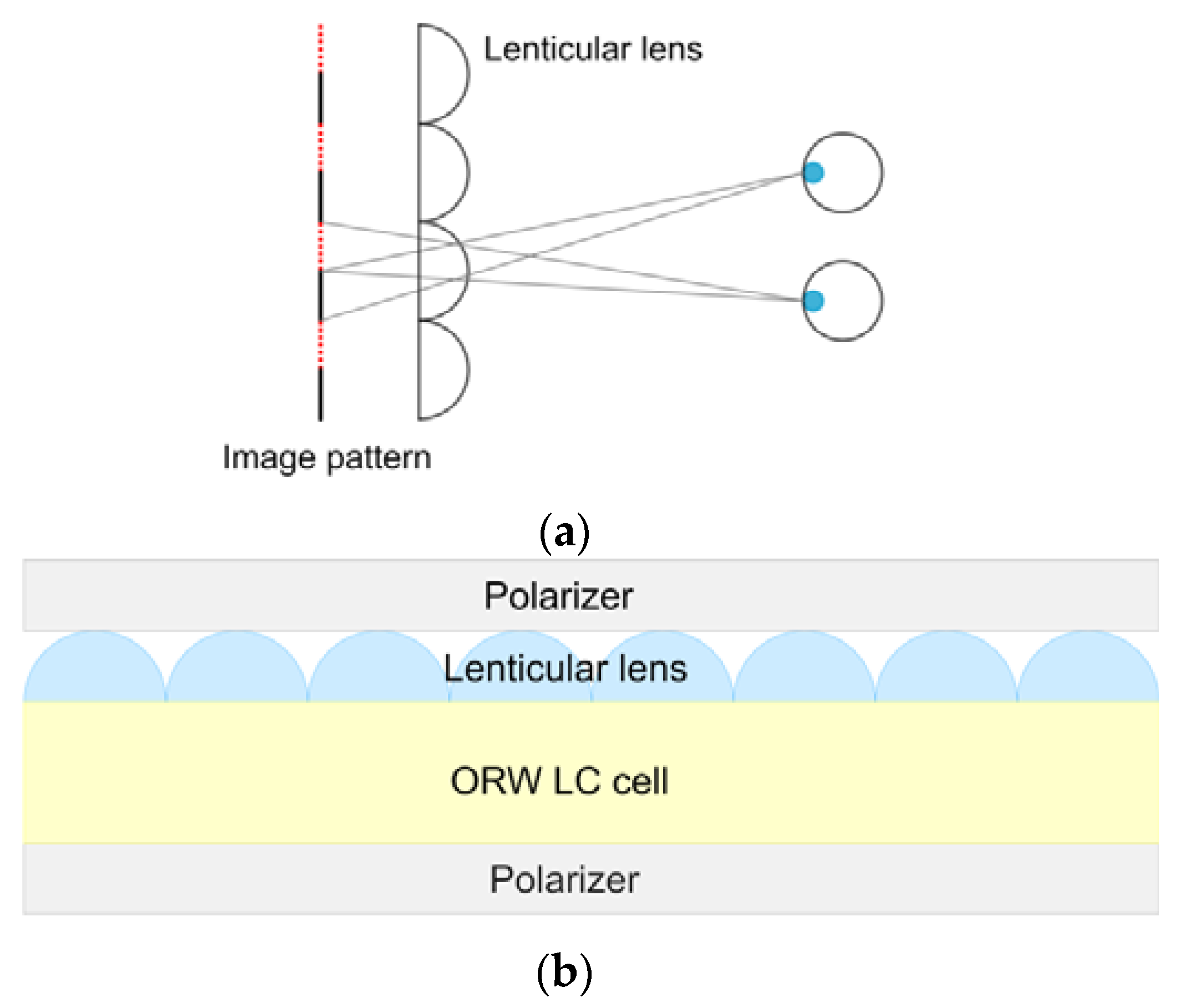
5.2. Lenticular Lens Array

Many possible applications of 3D displays do not assume the wearing of glasses. Spatial angular separation of light from e-paper can be used to achieve the glasses-free (autostereoscopic) viewing of multi-perspective 3D content. This is typically achieved using a lenticular lens. However, there exist several techniques to achieve a 3D effect without stereoscopic glasses [36].
The approach with a lenticular lens to 3D image formation on e-paper represents a reliable method [37]. According to this method, the display is the source of different optical paths of the recorded image pattern (see Figure 8a). If we place an ORW LC cell behind a large lens system, multiple projectors will be displayed and combined with complex optical switching (see Figure 8b).
The image formation process seems to be complicated because the ORW cell must be exposed twice through the aligning mask; however, a single exposure technique is highly desirable for 3D image formation. The solution to this problem is described below.
At the first stage, an optically rewritable cell must be assembled [37]. Then, the image mask for left and right eyes must be generated. A simple solution is to use any advanced graphics editor, which allows for the decomposing of the original image for the left and right eye (second stage). Here, the image resolution plays a crucial role in the adjustment of the line width. Finally, the two images must be integrated into a single 3D image that matches to the period of the lenticular lens with a negligible birefringence.
Image mask and the ORW cell must be combined in the third stage. In this stage, the photosensitive azo dye layer undergoes photoalignment, and the desired image features are obtained. The image on the ORW cell can also be erased and rewritten with a different image mask. As an example, we show the images of a dragon and a tiger (see Figure 9a), which were modified using a graphics editor (Figure 9b).
The lenticular lenses were designed in such a way that different images are magnified when an observer views at close angles. As long as the pattern size of the image matches the period of the lenticular lens, two different images are simultaneously seen by the observer. The lenticular lens array of 70 lines/inches was carefully adjusted and bonded to the ORW cell together with the two crossed polarizers. In this case, one lens covers two pixels, i.e., for left and right eye.
The image quality highly depends on how well the lenticular lens array is aligned. For example, if the image resolution is ~140 ppi, the pixel size is about 180 μm. Assuming that a typical mismatch should not exceed 10% of the image resolution, the threshold mismatch must be 18 μm, i.e., smaller than 50 μm (human eye resolution at the distance of 25 cm). Thus, we believe that with this tolerance in the alignment, the image quality of the proposed autostereoscopic 3D displays is acceptable, and does not have any serious visible effects.
The two pictures were taken at close viewing angles. For the sake of the convenience of the discussion, we only compare some parts of the image for left and right eye. Figure 10a,b depicts the images of the dragon for left and right eye, respectively. Red-circled dragon’s claw shows the difference between the observed images. In a similar manner, Figure 10c,d depict images of the tiger for left and right eye, respectively. One can see the tiger’s paw is different.
When this image is viewed within the angle of ±30°, the observer perceives its 3D shape. The optimum viewing distance is about 50 cm. Due to a minor mismatch between the lenticular lens and the pattern on the ORW cell, we observe a partially blurred image. The crosstalk of the two images depends on the quality of the lenticular lens.
Current lenticular lens technique presents additional challenges for the application of vision systems. For example, it is sensitive to horizontal head position because of spatial separation between the left and right eye views. As the viewer moves horizontally across viewing zones, pseudoscopic—or reverse stereo—viewing occurs with a traditional fixed lenticular lens.
We remark that all the generated images (Figure 2, Figure 3, Figure 6, Figure 7 and Figure 10) must be protected from the light (λ < 450 nm) if the security film is used outdoors. A solution for this issue is to use filters for the absorption of undesired wavelengths within the absorption spectra of azo dyes [5]. Due to the waveguide mode, the image quality does not depend on the cell gap.

6. Conclusions

In summary, we have considered the ORW technique as an element base for 3D and color electronic paper. One of the main problems of ORW e-paper is the limited number of grayscale levels. We have revealed the origin of this issue and theoretically analyzed that the performance of grayscale has the potential to be enhanced through the modulation of the exposure intensity. However, the study of the grayscale depth represents another research problem.
Based on the fact that the structure of azo dye layer governs the reflective characteristics of the liquid crystal layer, we have examined several optically sensitive prototypes. Complex security films provide enhanced safety because they possess four states, which require different polarizers for observation.
There exist two effective techniques of 3D visualization: stereoscopic and lenticular lens array. The recorded images are kept on 3D ORW e-paper for several days without any power consumption. The experimental 3D ORW e-paper devices are monochrome, but color images are possible. Examination of the performance characteristics of prototype color ORW e-paper shows that a set of ordered filters can be applied to obtain colored images. The influence of undesirable effects on human perception is discussed.
Based on waveguide geometry of ORW e-paper and the possibility of recording the pattern on optically sensitive film, various twisted structures of the nematic LC are possible. The demonstrated techniques enable us to fabricate many perspectives on optically rewritable devices, which operate under ambient light conditions, providing promising and energy efficient way for fabrication of novel gadgets.

Author Contributions

Writing—review and editing, V.C., A.K. and J.S. All authors have read and agreed to the published version of the manuscript.

Funding

This research was funded by the Russian Science Foundation, grant number 20-19-00201.

Institutional Review Board Statement

Not applicable.

Informed Consent Statement

Not applicable.

Data Availability Statement

The authors declare that all data supporting this review are available within the article and its supplementary references. The data that support the findings of this study are available on request from the corresponding author, A.K.

Conflicts of Interest

The authors declare no conflict of interest.

References

  1. Fergason, J. Liquid crystals: A big case for display. I. Opt. Spectra 1978, 12, 54–59. [Google Scholar]
  2. Fergason, J.; Berman, A. A push/pull surface-mode liquid-crystal shutter: Technology and applications. Liq. Cryst. 1989, 5, 1397–1404. [Google Scholar] [CrossRef]
  3. Heikenfeld, J.; Zhou, K.; Kreit, E.; Raj, B.; Yang, S.; Sun, B.; Milarcik, A.; Clapp, L.; Schwartz, R. Electrofluidic displays using Young–Laplace transposition of brilliant pigment dispersions. Nat. Photonics 2009, 3, 292–296. [Google Scholar] [CrossRef]
  4. Quiroga, J.A.; Canga, I.; Alonso, J.; Crespo, D. Reversible photoalignment of Liquid crystals: A path toward the creation of Rewritable Lenses. Sci. Rep. 2020, 10, 5739. [Google Scholar] [CrossRef] [PubMed] [Green Version]
  5. Chigrinov, V.; Kozenkov, V.; Kwok, H. Photoaligning: Physics and Applications in Liquid Crystal Devices; John Wiley & Sons: Hoboken, NJ, USA, 2008. [Google Scholar]
  6. Lin, T.; Xie, J.; Zhou, Y.; Zhou, Y.; Yuan, Y.; Fan, F.; Wen, S. Recent Advances in Photoalignment Liquid Crystal Polarization Gratings and Their Applications. Crystals 2021, 11, 900. [Google Scholar] [CrossRef]
  7. Chigrinov, V.; Kudreyko, A.; Guo, Q. Patterned Photoalignment in Thin Films: Physics and Applications. Crystals 2021, 11, 84. [Google Scholar] [CrossRef]
  8. Chigrinov, V.G.; Kudreyko, A.A.; Podgornov, F.V. Optically Rewritable Liquid Crystal Displays: Characteristics and Performance. Crystals 2021, 11, 1053. [Google Scholar] [CrossRef]
  9. Chigrinov, V.G.; Kudreyko, A.A. Tunable optical properties for ORW e-paper. Liq. Cryst. 2021, 48, 1073–1077. [Google Scholar] [CrossRef]
  10. Kudreyko, A.; Chigrinov, V. Optimization of image writer modes for optically rewritable electronic paper. Liq. Cryst. 2021, 1–6. [Google Scholar] [CrossRef]
  11. Chigrinov, V.; Sun, J.; Wang, X. Photoaligning and photopatterning: New LC technology. Crystals 2020, 10, 323. [Google Scholar] [CrossRef] [Green Version]
  12. Muravsky, A.; Murauski, A.; Chigrinov, V.; Kwok, H.-S. Light printing of grayscale pixel images on optical rewritable electronic paper. Jpn. J. Appl. Phys. 2008, 47, 6347. [Google Scholar] [CrossRef]
  13. Sun, J.; Srivastava, A.K.; Zhang, W.; Wang, L.; Chigrinov, V.G.; Kwok, H.S. Optically rewritable 3D liquid crystal displays. Opt. Lett. 2014, 39, 6209–6212. [Google Scholar] [CrossRef] [PubMed]
  14. Ma, Y.; Xin, S.J.; Liu, X.; Liu, Y.; Sun, J.; Wang, X.; Guo, Q.; Chigrinov, V.G. Colour generation for optically driving liquid crystal display. Liq. Cryst. 2020, 47, 1729–1734. [Google Scholar] [CrossRef]
  15. Li, J.; Bisoyi, H.K.; Tian, J.; Guo, J.; Li, Q. Optically rewritable transparent liquid crystal displays enabled by light-driven chiral fluorescent molecular switches. Adv. Mater. 2019, 31, 1807751. [Google Scholar] [CrossRef]
  16. Chigrinov, V.; Sun, J.; Kuznetsov, M.; Belyaev, V.; Chausov, D. 38-1: Invited Paper: Liquid Crystal Applications in e-Paper and Security Films: New Trends. In Proceedings of the SID Symposium Digest of Technical Papers, Campbell, CA, USA, 17–21 May 2021; pp. 515–518. [Google Scholar]
  17. Chigrinov, V.G.; Kozenkov, V.M.; Kwok, H.-S. Photoalignment of Liquid Crystalline Materials: Physics and Applications; John Wiley & Sons: Hoboken, NJ, USA, 2008; Volume 17. [Google Scholar]
  18. Kiselev, A.D.; Chigrinov, V.; Huang, D.D. Photoinduced ordering and anchoring properties of azo-dye films. Phys. Rev. E 2005, 72, 061703. [Google Scholar] [CrossRef] [Green Version]
  19. Chigrinov, V.; Pikin, S.; Verevochnikov, A.; Kozenkov, V.; Khazimullin, M.; Ho, J.; Huang, D.D.; Kwok, H.-S. Diffusion model of photoaligning in azo-dye layers. Phys. Rev. E 2004, 69, 061713. [Google Scholar] [CrossRef] [Green Version]
  20. Qin, Z.; Chen, Y.W.; Lin, F.C.; Hung, C.M.; Shieh, H.P.D.; Huang, Y.P. Ambient-light-adaptive image quality enhancement for full-color e-paper displays using a saturation-based tone-mapping method. J. Soc. Inf. Disp. 2018, 26, 153–163. [Google Scholar] [CrossRef]
  21. Kroeker, K.L. Electronic paper’s next chapter. Commun. ACM 2009, 52, 15–17. [Google Scholar] [CrossRef]
  22. Eshkalak, S.K.; Khatibzadeh, M.; Kowsari, E.; Chinnappan, A.; Jayathilaka, W.; Ramakrishna, S. Overview of electronic ink and methods of production for use in electronic displays. Opt. Laser Technol. 2019, 117, 38–51. [Google Scholar] [CrossRef]
  23. Heikenfeld, J.; Drzaic, P.; Yeo, J.S.; Koch, T. A critical review of the present and future prospects for electronic paper. J. Soc. Inf. Display 2011, 19, 129–156. [Google Scholar] [CrossRef] [Green Version]
  24. He, Y.; Li, J.; Li, J.; Zhu, C.; Guo, J. Photoinduced dual-mode luminescent patterns in dicyanostilbene-based liquid crystal polymer films for anticounterfeiting application. ACS Appl. Polym. Mater. 2019, 1, 746–754. [Google Scholar] [CrossRef]
  25. Stoykova, E.; Van Paepegem, W.; De Pauw, S.; Degrieck, J.; Sainov, V. Study of mechanical characteristics of window security films by phase-stepping photoelasticity. In Proceedings of the 15th International School on Quantum Electronics: Laser Physics and Applications, Bourgas, Bulgaria, 19 December 2008; pp. 220–230. [Google Scholar]
  26. Xu, Y.; Li, Y.; Meng, Y.; Li, H. Mechanofluorochromic carbon dots under grinding stimulation. Nanoscale 2020, 12, 16433–16437. [Google Scholar] [CrossRef] [PubMed]
  27. Li, X.; Kozenkov, V.M.; Yeung, F.S.-Y.; Xu, P.; Chigrinov, V.G.; Kwok, H.-S. Liquid-crystal photoalignment by super thin azo dye layer. Jpn. J. Appl. Phys. 2006, 45, 203. [Google Scholar] [CrossRef]
  28. Hasebe, H.; Kuwana, Y.; Yamazaki, O.; Takeuchi, K.; Takatsu, H. UV-curable liquid crystal for a retarder. Mol. Cryst. Liq. Cryst. 2010, 516, 45–47. [Google Scholar] [CrossRef]
  29. Guo, L.J. 54.1: Invited Paper: Structural Colors for Display and E-paper Applications. In Proceedings of the SID Symposium Digest of Technical Papers, Campbell, CA, USA, 1–6 June 2014; pp. 781–784. [Google Scholar]
  30. Lee, J.-K.; Lim, Y.-S.; Park, C.-H.; Park, Y.-I.; Kim, C.-D.; Hwang, Y.-K. a-Si: H thin-film transistor-driven flexible color E-paper display on flexible substrates. IEEE Electron Device Lett. 2010, 31, 833–835. [Google Scholar]
  31. Nose, M.; Yoshihara, T. Quantification of image quality for color electronic paper. J. Soc. Inf. Display 2012, 20, 624–631. [Google Scholar] [CrossRef]
  32. Zhang, Y.; Sun, J.; Liu, Y.; Shang, J.; Liu, H.; Liu, H.; Gong, X.; Chigrinov, V.; Kowk, H.S. A flexible optically re-writable color liquid crystal display. Appl. Phys. Lett. 2018, 112, 131902. [Google Scholar] [CrossRef]
  33. Lipton, L.; Starks, M.R.; Stewart, J.D.; Meyer, L.D. Stereoscopic Television System. U.S. Patent No. 4,523,226, 11 June 1985. [Google Scholar]
  34. Deng, Q.-L.; Su, W.-C.; Chen, C.-Y.; Lin, B.-S.; Ho, H.-W. Full color image splitter based on holographic optical elements for stereogram application. J. Disp. Technol. 2013, 9, 607–612. [Google Scholar] [CrossRef]
  35. Zhang, W.; Sun, J.; Srivastava, A.K.; Chigrinov, V.G.; Kwok, H.S. Paper No S9. 3: 3-D Grayscale Images Generation on Optically Rewritable Electronic Paper. In Proceedings of the SID Symposium Digest of Technical Papers, Campbell, CA, USA, 21 May–1 June 2015; p. 40. [Google Scholar]
  36. Dodgson, N.A. 3D without the glasses. Nature 2013, 495, 316–317. [Google Scholar] [CrossRef]
  37. Wang, X.Q.; Wang, L.; Sun, J.T.; Srivastava, A.K.; Chigrinov, V.G.; Kwok, H.S. Autostereoscopic 3D pictures on optically rewritable electronic paper. J. Soc. Inf. Display 2013, 21, 103–107. [Google Scholar] [CrossRef]
Figure 1. Color online. (a) Kinetics of the relative order parameter under different exposure modes (Parameters: A0 = 20, D = 2.6 × 10⁻⁴ s−1, a/kT = −6.5); (b) derivative of the relative order parameter.
Crystals 12 00364 g001
Figure 2. Demonstration of ORW e-paper for QR codes and security film: (a) photoaligned LC cell; (b) visualization of the hidden QR code.
Crystals 12 00364 g002
Figure 3. Color online. (a) Dark state; (b) bright state with rotated linear polarizer; (c) bright and (d) dark states with left (right) circular polarizer.
Crystals 12 00364 g003
Figure 4. Color online. (a) Formation of bright and dark states. Double-headed arrows indicate the orientation of polarizer and analyzer. (b) Chart of realizing red color with patterned mask.
Crystals 12 00364 g004
Figure 5. Color online. Schematic representation of optically rewritable e-paper, which is transparent for red color. The width of each color line ~1 mm.
Crystals 12 00364 g005
Figure 6. Color online. (a) Transmissive mode of ORW e-paper; (b) reflective mode of ORW e-paper.
Crystals 12 00364 g006
Figure 7. Color online. (a) Operation principle of stereoscopic ORW e-paper; (b,c) visualization of 3D effect with polarizing glasses.
Crystals 12 00364 g007
Figure 8. Color online. (a) The principle of the three-dimensional display by using the lenticular lens; (b) structure of three-dimensional display system.
Crystals 12 00364 g008
Figure 9. (a) Original images; (b) photo-edited images for image mask.
Crystals 12 00364 g009
Figure 10. Autostereoscopic image: (a) left eye viewed dragon; (b) right eye viewed dragon;(c) left eye viewed tiger; (d) right eye viewed tiger.
Crystals 12 00364 g010
Publisher’s Note: MDPI stays neutral with regard to jurisdictional claims in published maps and institutional affiliations.

