1. Introduction
Mixing and segregation of particles and bubbles in microfluidics are at the core of several multiphase micron- and nano-scale applications related to lab-on-a-chip devices, drug production and nanotechnology. For small-scale applications, viscosity effects dominate over inertial ones such that the fluid dynamics is well approximated by the creeping flow model. In such fluid flows, efficient mixing must be achieved by chaotic advection [
1]. When particle-laden flows are considered, the mixing properties of the background flow have a significant impact on the particle trajectories, even if the orbit of a particles differs from the pathline of a tracer. Particle-to-fluid density mismatch [
2,
3], buoyancy effects [
4], bulk finite-size effects correlated to high-strain regions of the flow [
5], and particle–boundary interactions [
6,
7,
8] may strongly affect the trajectory of a particle leading to segregation, accumulation or de-mixing of particles.
Recent studies focused on the transport and the creation of particle coherent structures in correlation with the kinematic template of the background flow. These Lagrangian coherent structures for the particulate phase tend to employ the linearly-mixing regions of the flow (regular regions in form of Kolmogorov–Arnol’d–Moser tori or invariant spheroids, [
9]) as skeleton for the accumulation. The emergence of particle coherent structures relies, in fact, on mechanisms that dissipate energy in phase space and transfer the particle from the chaotic regions of the fluid flow to the regular or weakly chaotic subdomains, where particles can get trapped and form robust accumulation patterns. Sources of the required dissipation can be the finite size of the particle [
5], inertia [
10,
11], particle–boundary interaction [
12,
13,
14,
15,
16,
17]. Most of such particle accumulation/segregation phenomena are governed, at leading order, by the single-particle dynamics and do not rely on the feedback effect of the particle on the fluid flow or on collective effects due to particle–particle interactions. For this reason, as we are interested in leading-order effects that can uncover novel accumulation phenomena, we will simplify the particle-laden flow as much as possible, using a one-way coupling for the particle dynamics.
In a recent study, Xu and Nadim [
18] demonstrate that the inertial centrifugation normally observed for heavy particles in a steady Kirchhoff vortex can be turned into centripetal motion if a pulsating Kirchhoff vortex is considered. This is what they term oscillatory counter-centrifugation. Under the assumption of negligible
, where
r is the radial coordinate of the particle, they carry our an order-of-magnitude analysis to show that the so-called oscillatory counter-centrifugation occurs for a given vortex pulsation threshold, which is function of the kinematic viscosity, the particle radius and the particle-to-fluid density ratio. The results of Xu and Nadim [
18], experimentally confirmed by [
19] (who investigated the agglomeration of fiber particles in periodic flows), have been further generalized by Romanò [
20], who showed that the Coriolis forces, responsible of reverting the centrifugation, lead to a rather more complex phenomenon termed Oscillatory Switching Centrifugation (OSC). In fact, Ref. [
20] demonstrated that, given the Stokes number and the particle-to-fluid density ratio, the asymptotic particle repellor at the vortex core can be turned into an asymptotic particle attractor and vice versa multiple times by increasing the vortex Strouhal number. Romanò [
20] also discussed the chaotic particle dynamics and their connection to the non-trivial limit cycles created at the boundaries (in parameter space) where particle centrifugation switches to centripetal motion and vice versa. Such a physical mechanism is relevant to microfluidic systems leading to centrifugal motion of particles, for instance confined cavities mounted on rotating disks and employed for automating life science analysis and synthesis protocols [
21]. Another domain of application of the OSC includes centrifugation devices at microscales, potentially integrated in lab-on-a-chip devices [
22].
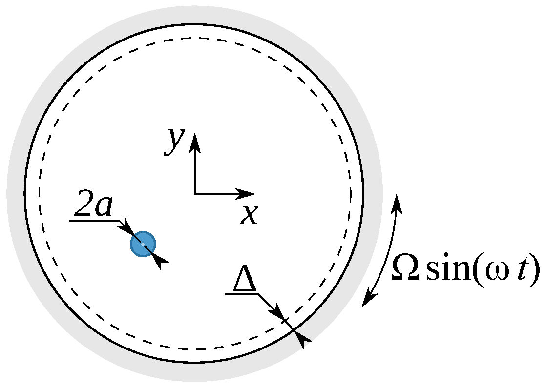
Building on the theoretical background established for the OSC for unbounded flows, in this paper we aim at investigating the effects of a confinement on the particle dynamics. We will focus on the dynamics of a small spherical particle in a cylindrical cavity, whose pulsating rotation generates the time-periodic Kirchhoff vortex. The paper is structured as follows: in
Section 2 the background flow is presented and the mathematical problem governing the particle motion is formulated;
Section 3 presents the results of our study, summarized and discussed in
Section 4.
2. Problem Formulation
A small rigid spherical particle of radius
a and density
is surrounded by a fluid of kinematic viscosity
and density
. The incompressible flow is confined within a hollow cylinder of internal radius
R and tangentially driven by the time periodic rotation of the moving boundary. The peripheral velocity of the rotating cylinder is
, and the pulsation frequency of its sinusoidal driving is
(see
Figure 1).
Under the assumption of creeping flow (
), and assuming a quasi-steady approximation of the Stokesian flow, the background flow is described by the two-dimensional time-periodic Kirchhoff vortex (see also [
20]). Hence, the stream function
and the fluid flow velocity
u yield
where
denotes the spatial coordinate. The time-periodic Kirchhoff flow is rotationally-invariant with respect to the elliptic point at the center of the vortex, i.e., at
. Moreover, since (
1) can be reduced to a one-dimensional time-periodic dynamics, it does not admit chaotic advection. In fact, the pathline of a perfect tracer is constrained to move along a circular trajectory such that
, with
and
being the initial location of the fluid element.
The dynamics of the small spherical particle is governed by the Maxey–Riley equation [
23]
where
t is the time,
v the particle velocity, and
g the gravity acceleration. The left-hand side of the Maxey–Riley equation represents the rate of change of the particle momentum, while the right-hand side of (
2) consists of the Basset history force, the added mass, the Stokes drag, the buoyancy force and the force exerted on the particle by the undisturbed flow. The Faxén correction [
24] is included by the
terms and it is identically zero since
for the flow (
1). The two notations used for the Lagrangian derivative, i.e.,
and
, refer to the material derivative along the particle trajectory
and along the fluid trajectory
where
A denotes an arbitrary vector field transported by
v and
u, respectively, and
is the Eulerian derivative.
Romanò [
20] showed that OSC is a phenomenon robust to memory-term perturbations hence the Basset-history force is neglected in the followings. Scaling the length, time and velocity by
R,
and
, neglecting also the gravitational forces, or assuming
g directed along the cylinder axis, the dimensionless form of the Maxey–Riley equation reads
The particle dynamics is characterized by two non-dimensional groups, i.e., the Stokes number
and the particle-to-fluid density ratio
, whereas the flow is governed by the Strouhal number
The Maxey–Riley equation is valid for small particles immersed in an unbounded creeping flow. Particles density-mismatched to the fluid can, however, interact with the inner surface of the cylindrical cavity in case they undergo an outward spiralling dynamics. It is therefore necessary to complement (
5) with a particle-boundary interaction model. Hereinafter, the particle–surface interaction (PSI) model of Hofmann and Kuhlmann [
25] is used, which models the interaction as an inelastic collision in radial direction and defines a sliding surface for the particle at distance
from the driving wall (
).
We stress that such a simplified particle–boundary interaction model has been proven successful at capturing the leading-order dynamics of interaction phenomena between small particles and driving boundaries (either walls or shear surfaces). This has been confirmed by comparison with fully-resolved simulations [
26,
27] and experiments [
28]. Moreover, recent studies show that the same non-trivial physics is predicted by employing the PSI model and more physically-sound interaction forces such as the augmented Stokes drag of [
6], see [
14,
15,
29].
3. Results
The particle dynamics is numerically simulated using the solver by Ref. [
20]. The initial particle position is
, the Stokes number is fixed to
, the particle-to-fluid density ratio is varied in the interval
and the Strouhal number of the flow ranges in
. As shown by [
26,
27,
28,
30],
is of the same order of magnitude of
a, hence in the followings we set
. All the simulations are run in dimensional form for
and
.
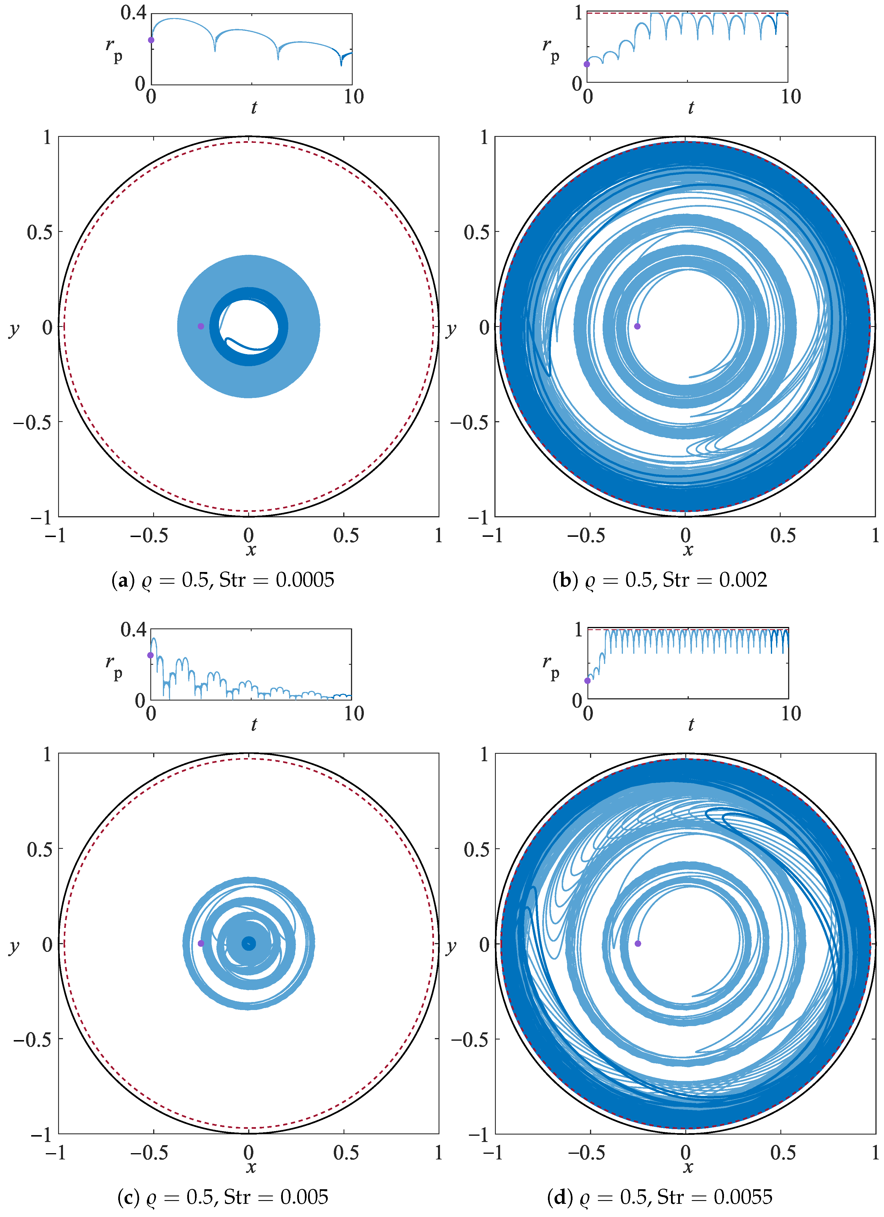
The graphical template used to compare the various particle dynamics consists of two representation of the same trajectory: (a) the top panel shows the radial position of the particle against the time t, and (b) the bottom panel depicts the particle orbit in the –plane. The light-blue line denotes the orbit over the whole integration time, darkblue color highlights the last 10% of the pathline, the purple dot shows the initial location of the particle and the red dashed line is at distance from the outer boundary and identifies the sliding surface for the particle interacting with the driving boundary.
At first, particles lighter than the fluid are considered.
Figure 2 depicts the trajectory of the same particle (
and
) immersed in four background flows with different Strouhal numbers, i.e.,
, 0.002, 0.005, and 0.0055. The change of the Strouhal number due to an increase of the pulsation frequency of the driving turns the centripetal motion for
to centrifugal for
, then back to centripetal for
and again to centrifugal for
. This demonstrates the phenomenon of the oscillatory switching centrifugation. When the particle is centrifuged against the solid boundary, it cannot penetrate the region between the red dashed line and the solid black line, hence it is forced to slide along the red line until the radial component of its velocity will pull it away from the rotating boundary. Owing to the complex dynamics inherited from the unbounded OSC, the confined particle trajectory gets attracted to a non-trivial manifold that rotates with an oscillatory character determined by the Strouhal number (cf.
Figure 2b,d).
This same behaviour is observed for
,
, and
. After an initial transient, the particle trajectory gets attracted by a complex rotating orbit (see
Figure 3a, bottom panel) that penetrates radially almost up to
(see
Figure 3a, top panel). Increasing further the Strouhal number, i.e., for
(see
Figure 3b), the attraction manifold sharpens, it becomes linelike and periodic, and it does not rotate inside the cylindrical cavity. Increasing even further the Strouhal number the oscillatory centrifugation switches multiple times to an oscillatory centripetal motion and vice versa as demonstrated in
Figure 3b–d. Once again for
(see
Figure 3d) a steady, periodic orbit is found with a characteristic shape qualitatively different from the limit cycle identified for
.
The occurrence of multiple non-co-existing attracting orbits is a robust feature of the particle dynamics. Indeed, qualitatively similar steady attracting orbits are observed for all the
and
located across the boundary in phase space where the centrifugal motion switches to centripetal and vice versa. This feature is inherited by the analogous limit cycles identified by Ref. [
20] for unbounded OSC, but a further stabilization of the periodic orbits is due to the presence of the solid boundary that confines the particle centrifugation. Hence, the unbounded limit cycle produced by the equilibrium between inertial effects due to particle-to-fluid density mismatch and the Coriolis force gets further squeezed against the driving wall and keeps being stabilized even beyond the centripetal-to-centrifugal switching boundary. As a result, the interplay between boundary confinement and centrifugal forces leads to the sharpening of the stabilized linelike attractor, as demonstrated in
Figure 4 for
.
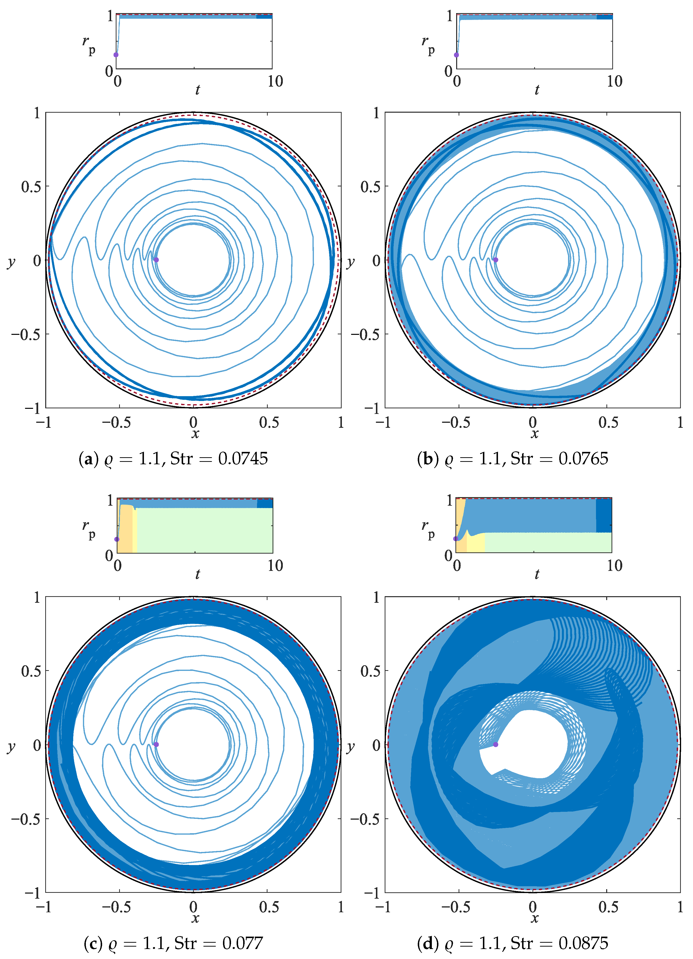
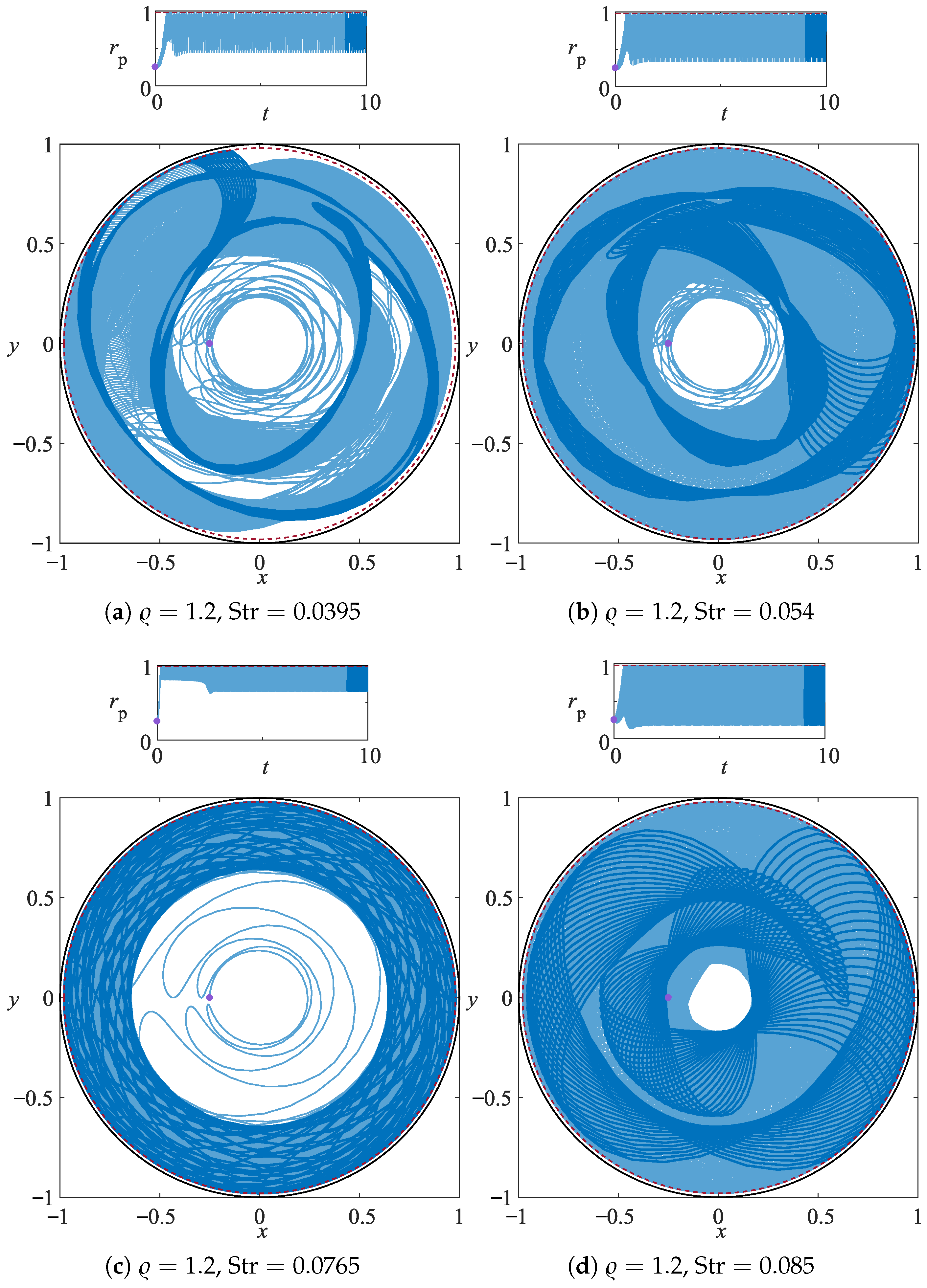
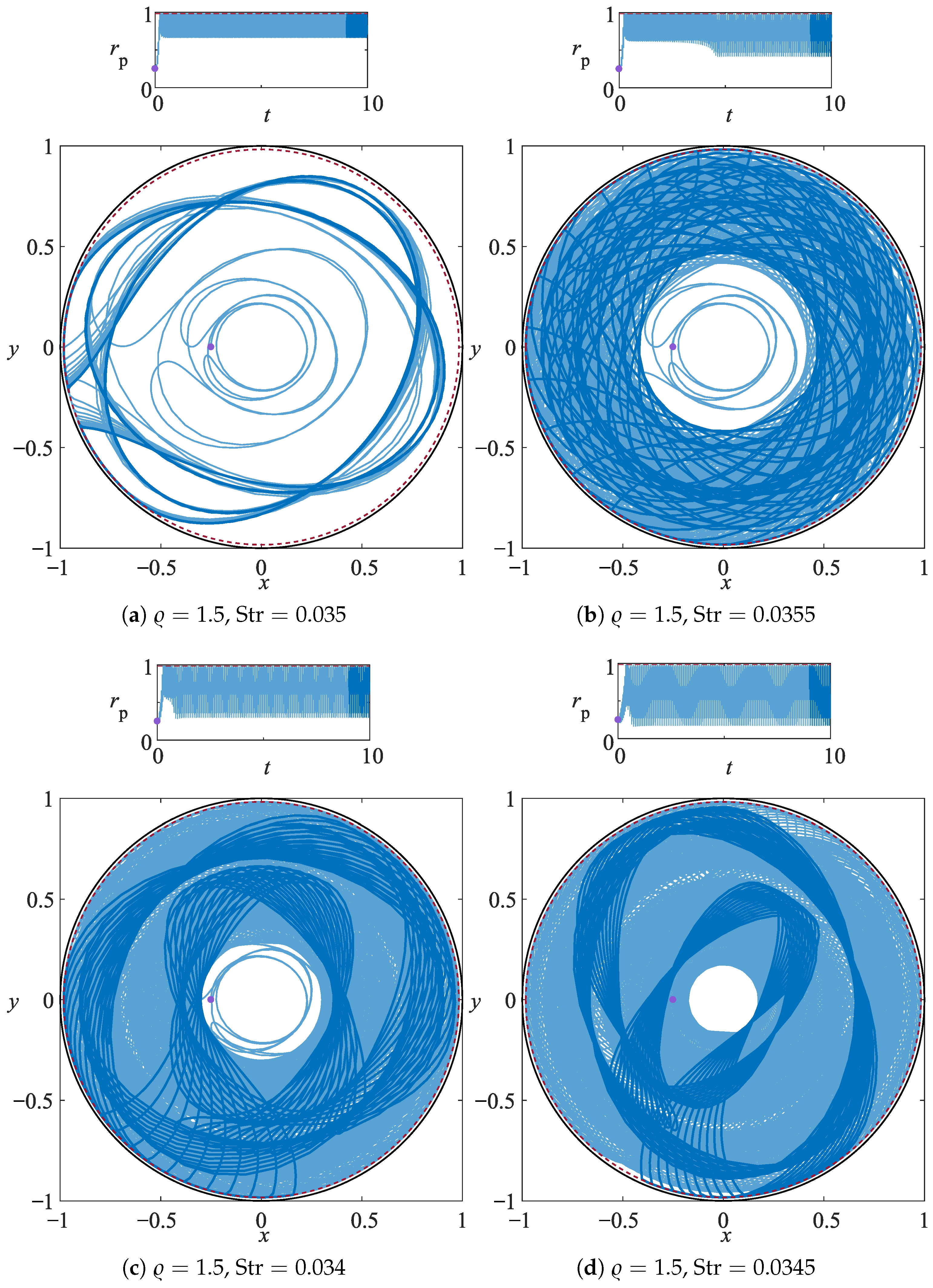
The features characterizing the confined OSC are demonstrated also for particles heavier than the fluid.
Figure 5 shows that a particle with
and
, which is normally subject to centrifugation for
, can be forced into a centripetal motion for
, then back to centrifugal for
and then it switches again to centriperal motion for
. This particle dynamics has already been extensively discussed and we will now focus on the emerging of the traveling attractor reported for
in
Figure 6.
In particular, we focus on the instability of the steady periodic limit cycle that turns into a traveling pattern if the Strouhal number exceeds a critical threshold. For
, the spherical particle is attracted to a linelike orbit that is sharply squeezed against the rotating wall. The linelike attractor slightly widens when increasing the Strouhal number to
. This qualitative trend is mirror symmetric with respect to the sharpening of the linelike pattern observed for light particles (see
,
Figure 4). Further increasing the pulsation frequency, hence increasing the Strouhal number, the time symmetry of the steady limit cycle gets broken and the traveling attractor emerges for
(see
Figure 6c) and invades the domain radially inward upon an increase of the Strouhal number (
, see
Figure 6d). The envelope of the time signals for particles attracted to a traveling manifold shows the distinct feature of a quick transition from the quasi-steady (unstable) attractor and the stable traveling attracting orbit. This quick transition is clearly observed in the time signal of
and it is always followed by an overshoot of the radial particle position. (see orange, yellow and green areas in the top panels of
Figure 5b,d and
Figure 6c,d).
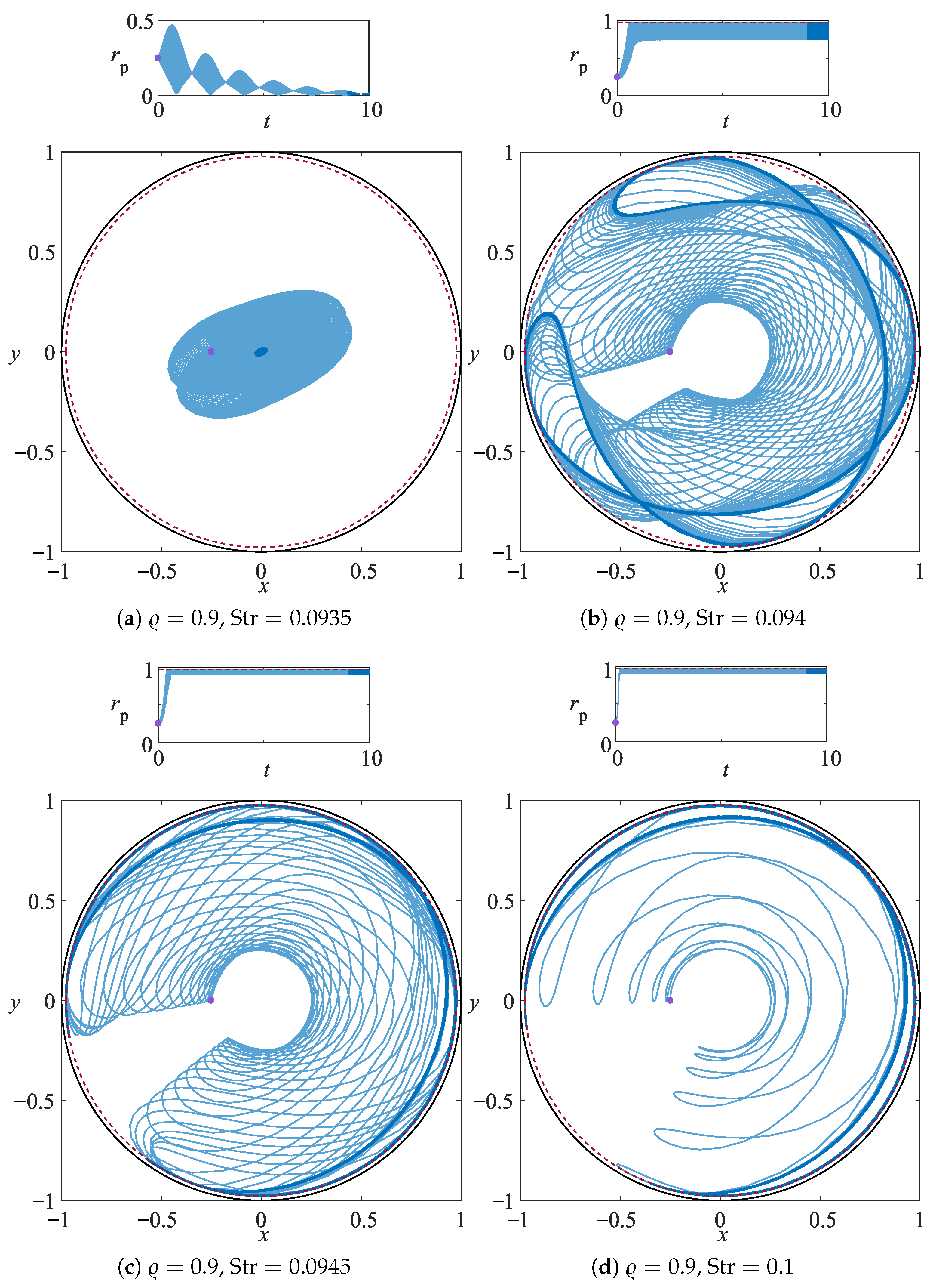
Figure 7 and
Figure 8 show that the traveling particle attractor is a robust feature of confined OSC for the range of particle-to-fluid density ratios considered in this study and they demonstrate that the penetration depth of the traveling attracting orbit can be controlled by varying the Strouhal number of the driving.
4. Discussion and Conclusions
The dynamics of a small rigid particle in a time-periodically rotating cylindrical cavity has been studied assuming that the background flow is given by a pulsating Kirchhoff vortex and the particle dynamics can be modeled by a simplified Maxey–Riley equation. Owing to the time-periodic driving, the particle trajectory is strongly affected by Coriolis forces that may induce OSC, as explained by Romanò [
20].
In this study we included the presence of solid walls, realizing, de facto, a set-up where confined OSC can be investigated experimentally. Despite the narrow particle-to-boundary interaction length , we find that the effect of the confinement on the particle dynamics is remarkable and leads to two distinct classes of attractors observed regardless of the sign of for all the Strouhal numbers leading to centrifugation. The first kind of attractor identified consists of a linelike limit cycle that sits steady in the domain while the walls of the cylindrical cavity rotate time-periodically. This attracting orbit is stable within a given range of Strouhal numbers that depends on the (and we expect it depends on , too). For , upon an increase of , the linelike attractor looses stability and starts widening up to a break of the time symmetry that leads to the attractor rotation.
We stress that despite the simple set-up of our study, the confined OSC can provide an effective mechanism for separating particles with different densities. This can be achieved by two different ways: (a) exploiting the mechanism of unbounded OSC, hence adjusting the Strouhal number such that some particles will be centrifuged and some others will be attracted to the vortex core, and (b) exploiting the steady linelike attractors described in this paper, hence selecting a Strouhal number that centrifuges all the particles of different and leads to their stationary accumulation along different limit cycles. Whenever a wide spectrum of is considered, a combination of such two particle segregation strategies is expected to be advantageous.
Finally, we remark the importance of the second class of attractors, i.e., the travelling attracting orbits. They may efficiently be used for creating colloids in lab-on-a-chip devices or in beads beating protocols commonly used in biological studies for promoting the lysis in microcentrifuges. In fact, as pointed out by [
18], the counter-centrifugation of inertial particles can be observed for oscillatory frequencies and rotation rates compatible with standard beads beating protocols. The Strouhal number could be used to control the penetration depth of the traveling attractors and, leading to very different patterns for different
, it could be used as effective control parameter to promote the collision of density-dispersed particles. We further remark that employing the OSC for separating stem cells of different density may be complementary to the use of other density-based separation techniques, such as the density gradient centrifugation [
31,
32] or the density gradient centrifugation–negative selection [
33].


