Abstract
We report here a high-power, highly efficient, wavelength-tunable nanosecond pulsed 1.7 μm fiber laser based on hydrogen-filled hollow-core photonic crystal fibers (HC-PCFs) by rotational stimulated Raman scattering. When a 9-meter-long HC-PCF filled with 30 bar hydrogen is pumped by a homemade tunable 1.5 μm pulsed fiber amplifier, the maximum average Stokes power of 3.3 W at 1705 nm is obtained with a slope efficiency of 84%, and the slope efficiency achieves the highest recorded value for 1.7 μm pulsed fiber lasers. When the pump pulse repetition frequency is 1.3 MHz with a pulse width of approximately 15 ns, the average output power is higher than 3 W over the whole wavelength tunable range from 1693 nm to 1705 nm, and the slope efficiency is higher than 80%. A steady-state theoretical model is used to achieve the maximum Stokes power in hydrogen-filled HC-PCFs, and the simulation results accord well with the experiments. This work presents a new opportunity for highly efficient tunable pulsed fiber lasers at the 1.7 μm band.
1. Introduction
Laser sources in the 1.7 μm band have many significant applications in material processing, mid-infrared laser generation, gas detection, medical treatment and bioimaging because there are many molecule absorption lines at this wave-band, which is also located in the transparent window of living tissue [1]. In past years, 1.7 μm fiber lasers have been intensively studied owing to their good stability and compact structure [2,3,4,5,6,7,8,9,10,11,12,13,14,15,16,17,18,19,20,21,22,23,24,25,26]. Up to now, dozens of watts continuous-wave (CW) fiber lasers at 1.7 μm have been demonstrated [2,3,4], but there are few studies on high-power pulsed fiber lasers in this waveband, which have unique advantages in some applications. High-power 1.7 μm laser pulses have been proven to achieve higher resolution and larger penetration depth in multi-photon microscopy [5,6], optical coherence tomography [7], and spectroscopic photoacoustic (PA) imaging [8,9]. Particularly, the PA needs nanosecond high-energy pulses to realize volumetric imaging with high resolution [9]. Moreover, high-power short pulses generate a smaller hot-melt area during material processing, which can achieve higher processing accuracy. In terms of gas detection, the absorption line of methane molecules is in the 1.7 μm band. Using 1.7 μm pulsed laser as the detection light can avoid the problem of heat accumulation caused by CW laser irradiation, and high power can increase the detection distance. Thus, it is necessary to improve the power of 1.7 μm pulsed fiber lasers to meet the demands of these important applications.
Table 1 presents the characteristics of some 1.7 μm pulsed fiber lasers based on solid-core fibers. It can be observed that different fiber-based solutions are proposed, and they can be mainly divided into two categories according to the gain mechanism. One is based on population inversion (PI) by using rare-earth-doped fibers, such as thulium-doped fibers (TDFs) [8,9,10,11], thulium-holmium co-doped fibers (THDFs) [12,13], and bismuth-doped fibers (BDFs) [14,15,16], to directly produce a signal at 1.7 μm. The other is based on nonlinear effects in the solid-core fibers, such as soliton self-frequency shift (SSFS) [17,18,19,20], four-wave mixing (FWM) [21,22,23], self-phase modulation (SPM) [7,24,25], and simulated Raman scattering (SRS) [26] to realize a wavelength conversion. As can be seen from Table 1, it is difficult to realize the high-power pulsed lasers with rare-earth-doped fibers, and their average powers are only milliwatt and slope efficiencies are low, especially THDFs and BDFs. This is because the TDFs have strong reabsorption in the 1.7 μm region and the fabrication of THDFs and BDFs is not mature. For the Raman soliton fiber lasers (RSFLs) based on SSFS, the output power of which is limited by the mode field area of the fibers, large mode area photonics crystal fibers (LMA PCFs) are always used as gain fibers. After using Er-doped polarization-maintaining very large mode area fibers (VLMAFs), the average output power can be up to 1.5 W, but this special kind of fiber is difficult to fabricate and not commercially available [20]. Furthermore, the output power of RSFLs fluctuates greatly in the wavelength tuning range because the wavelength tuning is accomplished by changing the input pump power. The FWM-based fiber optical parametric oscillator (FOPO) has been demonstrated to operate at 1.7 μm using dispersion-shifted fibers (DSFs) [21], but the output average power is only at milliwatt level due to the nonlinearity of fibers. To further increase the output power, the fiber optical parametric chirped-pulse amplifier (FOPCA) is proposed on the basis of FOPO, but the maximum average power is only 1.42 W after using polarization-maintaining dispersion-shifted fibers (PM DSFs) [22]. Furthermore, the FOPO and FOPCA also raise the issue of noise, affecting the output performance. The super-continuum (SC) generation mainly based SPM is another common solution to generate 1.7 μm laser pulses by using highly nonlinear fibers (HNLFs) or dispersion-compensating fibers (DCFs) [7,24,25]. However, with this method, it is difficult to achieve accurate spectrum control, causing a wide spectrum and low spectral density at 1.7 μm. Recently, a pulsed Raman fiber laser with an average power of 23 W has been reported, but its slope efficiency is low due to a cascaded seventh order Stokes shift, and its pulse width is limited due to modulation of gain switch [26]. In recent years, fiber gas Raman lasers (FGRLs) based on gas-filled hollow-core fibers (HCFs) have attracted great interest due to their potential in realizing tunable and new wavelength laser emissions [27,28,29,30,31,32,33,34,35,36,37,38,39], which provides a possible means of way to generating high-power, highly efficient pulsed fiber laser sources operating in the 1.7 μm band.

Table 1.
Characteristics of 1.7 μm pulsed fiber lasers based on solid-core fibers.
In this paper, we demonstrate a multi-watt, highly efficient, tunable nanosecond pulsed fiber laser source at 1.7 μm based on hollow-core photonic crystal fibers (HC-PCFs) by H2 rotational SRS. The pump source is a homemade high-power 1.5 μm pulsed fiber amplifier seeded by a tunable diode laser. When the operation wavelength of the seed is tuned to 1550 nm and the pump pulse repetition frequency is 1.3 MHz with a pulse width of approximately 15 ns, the maximum average Stokes power of 3.3 W at 1705 nm with a slope efficiency of 84% is obtained in a 9-meter-long HC-PCF filled with 30 bar H2, and the slope efficiency achieves the highest recorded value for 1.7 μm pulsed fiber lasers. Over the operation wavelength range from 1693 to 1705 nm, the slope efficiency is higher than 80%, and the average Stokes power is higher than 3 W, and Stokes pulse retains a good Gaussian shape with a pulse width of appromxiately 13 ns. Furthermore, a steady-state theoretical model considering the second-order Raman conversion is used to find the optimal repetition frequency to obtain the maximum Stokes power in this single-pass FGRL, and the simulation results agree well with the experiments.
2. Experimental Setup
Figure 1a presents the experimental setup, which is similar to our previous experiments [38], but we used a higher power pump source and a shorter HC-PCF to achieve higher efficiency and Stokes power. The pump source is a homemade 1.5 μm pulsed fiber amplifier which consists of a CW tunable 1.5 μm seed diode laser (CobriteDX1, ID Photonics, Germany), an acousto-optic modulator (AOM, Fibre-Q, Gooch & Housego, England), a tunable fiber filter, and home-made three stages of erbium-doped fiber amplifiers (EDFAs. Due to the limitation of the amplification ability of EDFAs, only in the wavelength range of 1540 to 1550 nm, the pump source can output a maximum average power of about 7.5 W. The AOM modulates the CW light into the Gaussian pulses, and both the pulse width and repetition frequency are tunable. The pulse width at the end of the EDFA3 was set to 15 ns to achieve steady-state SRS and the repetition frequency was only adjusted in the range of 0.7 to 2 MHz in this work. The tunable filter is used to suppress the amplified spontaneous emission (ASE). The fiber coupler with a coupling ratio of 99:1 is used to monitor the pump power in real time. The main output fiber (SMF-28e, Corning, America) of coupler is directly fusion spliced to a 9-meter-long HC-PCF (HC-1550-02, NKT Photonics, Denmark) owing to their similar mode field area, and the splice loss is approximately 1.4 dB, which is close to the theoretical minimum loss [40]. The other end of the HC-PCF is sealed in a gas cell with a glass window, which is used to fill the HC-PCF with H2 to 30 bar. The Stokes light and the residual pump light transmitted from the glass window are collimated by a plano-convex lens, and then sent to an optical spectrum analyzer (OSA, AQ6370D, Yokogawa, Japan) or a power meter (S470C, Thorlabs, America) by a silver mirror. A long-pass filter (transmission approximately 95% > 1600 nm) placed in front of the power meter is used to filter the residual pump light.
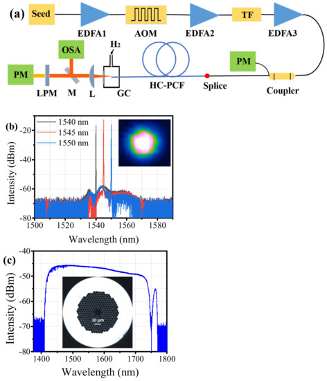
Figure 1.
(a) Experimental setup: EDFA, erbium-doped fiber amplifier, AOM, acoustic optical modulator, TF, tunable fiber filter, GC, gas cell, L, convex-plane lens, M, silver mirror, LPF, long-pass filter, PM, power meter, OSA, optical spectrum analyzer; (b) The spectra of pump source at different wavelengths at the maximum output power. Insert: the near-field pattern of the pump beams; (c) The measured transmission spectrum of the 9-meter-long HC-PCF. Insert: the measured optical microscope image of cross section of the HC-PCF.
Figure 1b presents the measured spectra of the pump source at different wavelengths at the maximum output power, and it can be observed that the ASE is more than 30 dB lower than the signal. The insert in Figure 1b presents the near-field pattern of the pump beams by a 20× microscope objective and a HgCdTe infrared camera (MCT-2327, spectral response 0.8–2.5 μm, Xenics, Belgium), as can be seen, the pump beams operate in a good fundamental mode. Figure 1c presents the measured transmission spectrum of the used 9-meter-long HC-PCF by a supercontinuum source (SuperK COMPACT, 450–2400 nm, NKT Photonics, Denmark). It can be observed that the low-loss transmission range of the HC-PCF is from approximately 1415 to 1740 nm, and there is a high loss peak near 1750 nm. The insert in Figure 1c presents the measured optical microscope image of cross section of the HC-PCF with core diameter of approximately 10 μm.
3. Results and Discussion
Figure 2a depicts the output spectra of different pump wavelengths at the maximum pump power when the repetition frequency is 1.3 MHz. It can be observed that the pump wavelengths from left to right are 1540, 1545 and 1550 nm, and the corresponding Stokes wavelengths are 1693, 1699 and 1705 nm, respectively, indicating that each pump line corresponds to only one Stokes line (rotational Raman frequency shift of 587 cm−1). This is because other Raman lines outside the transmission band are suppressed due to high fiber loss, such as the vibrational Stokes line (Raman frequency shift of 4155 cm−1). However, from Figure 2b, it can be observed that there are two Raman lines except the 1540 nm pump line in the output spectrum when the repetition frequency is 1 MHz and the pump power is maximum, which can be attributed to the conversion of the 1693 nm first-order Raman line to the 1801 nm second-order Raman line (rotational Raman frequency shift of 354 cm−1). The occurrence of this conversion indicates that the peak power of the first-order Raman pulse exceeds the second-order Raman threshold when the repetition frequency is 1 MHz. Owing to the high fiber loss, the second-order Raman power is very weak. It is difficult to accurately measure the second-order Raman power under our experimental condition, but it can be observed by high-sensitivity OSA and its power level can be estimated by the spectral intensity.
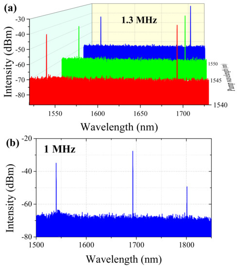
Figure 2.
(a) Output spectra of different pump wavelengths at the maximum pump power when the repetition frequency is 1.3 MHz; (b) Output spectrum of 1540 nm pump wavelength at the maximum pump power when the repetition frequency is 1 MHz.
The pulse shapes and series are measured by a fast photodetector (EOT ET5000, wavelength 850 to 2150 nm, bandwidth 12.5 GHz) and a broadband oscilloscope (Tektronix MDO3104, bandwidth 1 GHz, sample rate 5 Gs/s) when the pump power is maximum and the repetition frequency of the pump pulse is 1.3 MHz, as indicated in Figure 3. The temporal characteristic of pump pulses was measured before coupling into the HC-PCFs, while the Stokes pulses were measured at the output end of HC-PCF after the residual pump light was completely filtered. It can be seen that the repetition frequency of Stokes pulses is 1.3 MHz, which is the same as the pump pulses, and the shapes for both pump pulse and Stokes pulses are Gaussian-type. Furthermore, because only the center part of pump pulses that is higher than Raman threshold can be converted into the Stokes light, the FWHM (full width at half maximum) of Stokes pulses is smaller than that of pump pulses [29]. Moreover, the rising edge of Stokes pulses is steeper due to the rapid conversion of pump light [28].
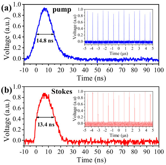
Figure 3.
Measured temporal characteristics of (a) pump pulses and (b) Stokes pulses when the pump power is maximum and repetition frequency is 1.3 MHz.
The rotational SRS process in this single-pass FGRL can be described by a simple steady-state theoretical model considering the second-order Raman conversion [41]:
where z is a coordinate of the fiber length; Pi is the intensity, αi is the fiber loss, λi is the wavelength and gi is the steady-state Raman gain coefficient (“I” means “S1” for the first-order Stokes, “S2” for the second-order Stokes, “P” for the pump wave). The boundary conditions can also be given [41]:
where P0 is the initial peak power of the pump pulse coupled into the HC-PCFs; h is the Planck constant; c is the light speed; ∆υR is the Raman linewidth; Aeff is the mode field area of the HC-PCFs. Using the above model for simulation, the first- and second order steady-state Raman gain coefficients can be estimated and slightly adjusted from Ref. [38,41,42], so gS1 = 0.25 cm/GW and gS2 = 0.17 cm/GW. The Raman linewidth ∆υR can be estimated as 3.1 GHz at room temperature [43]. The HC-PCFs loss λp = 0.04 dB/m, λs1 = 0.11 dB/m, λs2 = 6 dB/m. The mode field diameter of HC-PCFs is approximately 9 μm, so the mode field area Aeff = 20.25π μm2.
The simulation curves of output Stokes and residual pump power with the repetition frequency are obtained when the pump power is 7.5 W and pump wavelength is 1540 nm, as illustrated by the dashed lines in Figure 4a. As can be seen, the maximum output Stokes power can be obtained near 1.3 MHz repetition frequency. Subsequently, by adjusting the repetition frequncy of pump pulses, the output Stokes power and the residual pump power at different repetition frequencies are measured, as illustrated in Figure 4a–d. The measured results shown in Figure 4a are the output Stokes and residual pump powers of different repetition frequencies at the maxium pump power. It can be observed that the measured results are essentially consistent with the simulation results. The measured results shown in Figure 4b–d are the evolutions of the Stokes power, Stokes pulse energy and residual pump power with the coupled pump power/pulse energy at different repetition frequencies, respectively. It can be observed from Figure 4b that when the repetition frequency is less than 1.3 MHz, the peak power of pump pulse becomes higher, so the Raman threshold of average pump power is reduced. Moerover, the peak power of the generated first-order Stokes pulse also becomes higher, and exceeds the second-order Raman threshold at high pump power level. Thus, the first-order Stokes power drops after reaching a peak as the pump power increases, indicating the conversion of first to second-order Stokes power. When the repetition is higher than 1.3 MHz, less pump power would convert into the first-order Stokes power due to the higher Raman threshold of average pump power. Thus, the optimal repetition frequency is 1.3 MHz, and the maximum Stokes power is approximately 3.1 W. From Figure 4c, it can be seen that the Raman threshold of pump pulse energy is constant at different repetition frequencies. This is not unexpected, because the Raman threshold of pump pulse peak power is constant, which is determined by the characteristics of gas and HC-PCFs. The purpose of adjusting repetition frequency is to set the appropriate peak power to obtain the maximum first-order Stokes power at 1.7 μm. It can be seen from Figure 4d that the residual pump power in the condition of maximum coupled pump power is increased with the increase in repetition frequency, which can be attribured to the increase in the Raman threshold of average pump power.
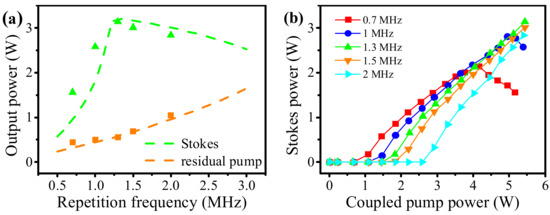
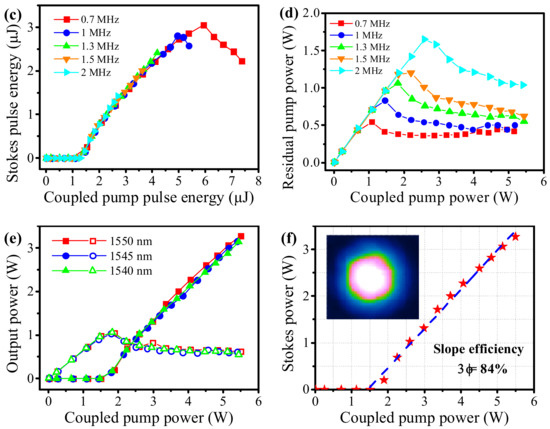
Figure 4.
(a) The simulation and measured results of Stokes and residual pump powers at different repetition frequency when the pump power is 7.5 W and pump wavelength is 1540 nm, and dash lines and solid patterns represent the simulation and measured results respectively; The evolutions of (b) Stokes power, (c) Stokes pulse energy and (d) residual pump power with the coupled pump power/pulse energy at different repetition frequency when the pump wavelength is 1540 nm; (e) The evolutions of Stokes and residual pump powers with the coupled pump power at different pump wavelengths when the repetition frequency is 1.3 MHz, and solid and hollow patterns represent the Stokes power and residual pump power respectively; (f) For the highest Stokes laser emission at 1705 nm, the evolution of output Stokes power with coupled pump power. Insert: the near-field pattern of the Stokes beams.
Furthermore, we measured the evolutions of the output Stokes and residual pump powers with the coupled pump power at different pump wavelengths when the repetition frequency was 1.3 MHz, as indicated in the Figure 4e. The solid and hollow patterns represent the Stokes power and residual pump power, respectively. It can be observed that the maximum Stokes power is achieved at 1550 nm, which is attributed to the performance of the pump source, and the pump power at 1550 nm is slightly higher. Thus, the maximum Stokes power is obtained at 1705 nm, and its evolution of output Stokes power with coupled pump power is specifically plotted in Figure 4f. It can be seen that the Stokes power increases linearly with coupled pump power beyond the Raman threshold, reaching a maximum of 3.3 W with 84% slope efficiency. Moreover, the power conversion efficiency in terms of the maximum coupled pump power of 5.5 W is aproximately 60%. Moreover, the near-field pattern of Stokes beams was measured, as indicated in the insert. It can be observed that the Stokes beams still operate in a fundamental mode. The good mode matching between the pump beams and Stokes beams is conductive to the high optical-optical conversion efficiency.
4. Conclusions
We have reported a multi-watt, highly efficient, tunable 1.7 μm pulsed fiber laser in hydrogen-filled HC-PCFs by rotational SRS. When a 9-meter-long HC-PCF filled with 30 bar H2 is pumped by a homemade high-power tunable 1.5 μm pulsed fiber amplifier, the maximum average Stokes power of 3.3 W at 1705 nm is obtained with a slope efficiency of 84%, to the best of our knowledge, the slope efficiency achieves the highest recorded value for 1.7 μm pulsed fiber lasers. When the pump pulse repetition frequency is 1.3 MHz with a pulse width of approximately 15 ns, over the whole wavelength tunable range from 1693 nm to 1705 nm, the average output power is higher than 3 W, and the slope efficiency is greater than 80%. A steady-state theoretical model is established to analyze the rotational SRS process in hydrogen-filled HC-PCFs, and the simulation results accord well with the experiments. No saturation was observed, so the output power can be further improved by increasing the pump power and the coupling efficiency.
Author Contributions
Conceptualization, Z.W. and H.L.; methodology, H.L.; software, W.H.; validation, Z.W., H.L. and W.P.; formal analysis, Z.W.; investigation, H.L.; resources, M.W.; data curation, W.P.; writing—original draft preparation, H.L.; writing—review and editing, Z.W.; visualization, H.L. All authors have read and agreed to the published version of the manuscript.
Funding
This research was funded by the Outstanding Youth Science Fund Project of Hunan Province Natural Science Foundation (2019JJ20023), National Natural Science Foundation of China (NSFC) (11974427, 12004431) and Fund of State Key Laboratory of Pulsed Power Laser Technology (SKL 2020 ZR05).
Data Availability Statement
The data presented in this study are available on request from the corresponding author. The data are not publicly available due to privacy.
Conflicts of Interest
The authors declare no conflict of interest.
References
- Zhang, Y.; Zhang, P.; Liu, P.; Han, K.; Du, Q.; Wang, T.; Zhang, L.; Tong, S.; Jiang, H. Fiber light source at 1.7 μm waveband and its applications. Chin. J. Lasers 2016, 53, 090002. [Google Scholar]
- Burns, M.D.; Shardlow, P.C.; Barua, P.; Jefferson-Brain, T.L.; Sahu, J.K.; Clarkson, W.A. 47 W continuous-wave 1726 nm thulium fiber laser core-pumped by an erbium fiber laser. Opt. Lett. 2019, 44, 5230–5233. [Google Scholar] [CrossRef] [PubMed]
- Zhang, L.; Dong, J.; Feng, Y. High-Power and High-Order Random Raman Fiber Lasers. Quantum Electron. 2018, 24, 1–6. [Google Scholar] [CrossRef]
- Zhang, Y.; Song, J.; Ye, J.; Xu, J.; Yao, T.; Zhou, P. Tunable random Raman fiber laser at 1.7 μm region with high spectral purity. Opt. Express 2019, 27, 28800–28807. [Google Scholar] [CrossRef]
- Cheng, H.; Tong, S.; Deng, X.; Liu, H.; Du, Y.; He, C. Deep-brain 2-photon fluorescence microscopy in vivo excited at the 1700 nm window. Opt. Lett. 2019, 44, 4432–4435. [Google Scholar] [CrossRef]
- Horton, N.G.; Xu, C. Dispersion compensation in three-photon fluorescence microscopy at 1,700 nm. Biomed. Opt. Express 2015, 6, 1392–1397. [Google Scholar] [CrossRef]
- Kawagoe, H.; Ishida, S.; Aramaki, M.; Sakakibara, Y.; Omoda, E.; Kataura, H. Development of a high-power supercontinuum source in the 1.7 μm wavelength region for highly penetrative ultrahigh-resolution optical coherence tomography. Biomed. Opt. Express 2014, 5, 932–943. [Google Scholar] [CrossRef]
- Li, C.; Shi, J.; Gong, X.; Kong, C.; Luo, Z.; Song, L. 1.7 μm wavelength tunable gain-switched fiber laser and its application to spectroscopic photoacoustic imaging. Opt. Lett. 2018, 43, 5849–5852. [Google Scholar] [CrossRef]
- Li, C.; Shi, J.; Wang, X.; Wang, B.; Gong, X.; Song, L. High-energy all-fiber gain-switched thulium-doped fiber laser for volumetric photoacoustic imaging of lipids. Photonics Res. 2020, 8, 160–164. [Google Scholar] [CrossRef]
- Li, C.; Kong, C.; Wong, K.K.Y. High Energy Noise-Like Pulse Generation from a Mode-Locked Thulium-Doped Fiber Laser at 1.7 μm. IEEE Photonics J. 2019, 11, 1–6. [Google Scholar] [CrossRef]
- Li, C.; Wei, X.; Kong, C.; Tan, S.; Chen, N.; Kang, J. Fiber chirped pulse amplification of a short wavelength mode-locked thulium-doped fiber laser. APL Photonics 2017, 2, 121302. [Google Scholar] [CrossRef]
- Du, T.; Ruan, Q.; Yang, R.; Li, W.; Wang, K.; Luo, Z. 1.7-μm Tm/Ho-Codoped All-Fiber Pulsed Laser Based on Intermode-Beating Modulation Technique. J. Lightwave Technol. 2018, 36, 4894–4899. [Google Scholar] [CrossRef]
- Noronen, T.; Okhotnikov, O.; Gumenyuk, R. Electronically tunable thulium-holmium mode-locked fiber laser for the 1700–1800 nm wavelength band. Opt. Express 2016, 24, 14703–14708. [Google Scholar] [CrossRef] [PubMed]
- Noronen, T.; Firstov, S.; Dianov, E.; Okhotnikov, O.G. 1700 nm dispersion managed mode-locked bismuth fiber laser. Sci. Rep. 2016, 6, 24876. [Google Scholar] [CrossRef] [PubMed]
- Khegai, A.; Melkumov, M.; Riumkin, K.; Khopin, V.; Firstov, S.; Dianov, E. NALM-based bismuth-doped fiber laser at 1.7 μm. Opt. Lett. 2018, 43, 1127–1130. [Google Scholar] [CrossRef] [PubMed]
- Thipparapu, N.K.; Wang, Y.; Wang, S.; Umnikov, A.A.; Barua, P.; Sahu, J.K. Bi-doped fiber amplifiers and lasers [Invited]. Opt. Mater. Express 2019, 9, 2446–2465. [Google Scholar] [CrossRef]
- Fang, X.; Wang, Z.Q.; Zhan, L. Efficient generation of all-fiber femtosecond pulses at 1.7 μm via soliton self-frequency shift. Opt. Eng. 2017, 56, 046107. [Google Scholar] [CrossRef]
- Nguyen, T.N.; Kieu, K.; Churin, D.; Ota, T.; Miyawaki, M.; Peyghambarian, N. High Power Soliton Self-Frequency Shift with Improved Flatness Ranging From 1.6 to 1.78 μm. IEEE Photonics Technol. Lett. 2013, 25, 1893–1896. [Google Scholar] [CrossRef]
- Wang, K.; Xu, C. Tunable high-energy soliton pulse generation from a large-mode-area fiber and its application to third harmonic generation microscopy. Appl. Phys. Lett. 2011, 99, 071112. [Google Scholar] [CrossRef]
- Zach, A.; Mohseni, M.; Polzer, C.; Nicholson, J.W.; Hellerer, T. All-fiber widely tunable ultrafast laser source for multimodal imaging in nonlinear microscopy. Opt. Lett. 2019, 44, 5218–5221. [Google Scholar] [CrossRef]
- Becheker, R.; Tang, M.; Hanzard, P.H.; Tyazhev, A.; Mussot, A.; Kudlinski, A. High-energy dissipative soliton-driven fiber optical parametric oscillator emitting at 1.7 μm. Laser Phys. Lett. 2018, 15, 115103. [Google Scholar] [CrossRef]
- Qin, Y.; Batjargal, O.; Cromey, B.; Kieu, K. All-fiber high-power 1700 nm femtosecond laser based on optical parametric chirped-pulse amplification. Opt. Express 2020, 28, 2317–2325. [Google Scholar] [CrossRef] [PubMed]
- Tang, M.; Becheker, R.; Hanzard, P.H.; Tyazhev, A.; Oudar, J.L.; Mussot, A. Low Noise High-Energy Dissipative Soliton Erbium Fiber Laser for Fiber Optical Parametric Oscillator Pumping. Appl. Sci. 2018, 8, 2161–2175. [Google Scholar] [CrossRef]
- Zeng, J.; Akosman, A.E.; Sander, M.Y. Supercontinuum Generation from a Thulium Ultrafast Fiber Laser in a High NA Silica Fiber. IEEE Photonics Technol. Lett. 2019, 31, 1787–1790. [Google Scholar] [CrossRef]
- Chung, H.Y.; Liu, W.; Cao, Q.; Kartner, F.X.; Chang, G. Er-fiber laser enabled, energy scalable femtosecond source tunable from 1.3 to 1.7 μm. Opt. Express 2017, 25, 15760–15771. [Google Scholar] [CrossRef] [PubMed]
- Grimes, A.; Hariharan, A.; Sun, Y.; Ovtar, S.; Kristensen, P.; Westergaard, P.G.; Rako, S.; Baumgarten, C.; Stoneman, R.C.; Nicholson, J.W.; et al. Hundred-Watt CW and Joule Level Pulsed Output from Raman Fiber Laser in 1.7-μm Band. In Proceedings of the SPIE 11260, Fiber Lasers XVII: Technology and Systems, San Francisco, CA, USA, 21 February 2020. [Google Scholar]
- Benabid, F.; Knight, J.C.; Antonopoulos, G.; Russell, P.S.J. Stimulated Raman scattering in hydrogen-filled hollow-core photonic crystal fiber. Science 2002, 298, 399–402. [Google Scholar] [CrossRef]
- Benabid, F.; Antonopoulos, G.; Knight, J.C.; Russell, P. Stokes amplification regimes in quasi-cw pumped hydrogen-filled hollow-core photonic crystal fiber. Phys. Rev. Lett. 2005, 95, 213903. [Google Scholar] [CrossRef]
- Chen, Y.; Wang, Z.; Gu, B.; Yu, F.; Lu, Q. Achieving a 1.5 μm fiber gas Raman laser source with about 400 kW of peak power and a 6.3 GHz linewidth. Opt. Lett. 2016, 41, 5118–5121. [Google Scholar] [CrossRef]
- Chen, Y.; Wang, Z.; Li, Z.; Huang, W.; Xi, X.; Lu, Q. Ultra-efficient Raman amplifier in methane-filled hollow-core fiber operating at 1.5 μm. Opt. Express 2017, 25, 20944–20949. [Google Scholar] [CrossRef]
- Gladyshev, A.V.; Kosolapov, A.F.; Khudyakov, M.M.; Yatsenko, Y.P.; Kolyadin, A.N.; Krylov, A.A. 4.4 μm Raman laser based on hollow-core silica fibre. Quantum Electron. 2017, 47, 491–494. [Google Scholar] [CrossRef]
- Cao, L.; Gao, S.F.; Peng, Z.; Wang, X.; Wang, Y.; Wang, P. High peak power 2.8 μm Raman laser in a methane-filled negative-curvature fiber. Opt. Express 2018, 26, 5609–5615. [Google Scholar] [CrossRef] [PubMed]
- Gladyshev, A.V.; Kosolapov, A.F.; Khudyakov, M.M.; Yatsenko, Y.P.; Kolyadin, A.N.; Krylov, A.A. 2.9, 3.3, and 3.5 μm Raman Lasers Based on Revolver Hollow-Core Silica Fiber Filled by H2/D2 Gas Mixture. IEEE J. Quantum Electron. 2018, 24, 0903008. [Google Scholar]
- Li, Z.; Huang, W.; Cui, Y.; Gu, B.; Wang, Z. High-Efficiency, High Peak-Power, Narrow Linewidth 1.9 μm Fiber Gas Raman Amplifier. J. Lightwave Technol. 2018, 36, 3700–3706. [Google Scholar] [CrossRef]
- Li, Z.; Huang, W.; Cui, Y.; Wang, Z. Efficient mid-infrared cascade Raman source in methane-filled hollow-core fibers operating at 2.8 μm. Opt. Lett. 2018, 43, 4671–4674. [Google Scholar] [CrossRef]
- Li, Z.; Huang, W.; Cui, Y.; Wang, Z.; Wu, W. 0.83 W, single-pass, 1.54 μm gas Raman source generated in a CH4-filled hollow-core fiber operating at atmospheric pressure. Opt. Express 2018, 26, 12522–12529. [Google Scholar] [CrossRef]
- Cui, Y.; Huang, W.; Li, Z.; Zhou, Z.; Wang, Z. High-efficiency laser wavelength conversion in deuterium-filled hollow-core photonic crystal fiber by rotational stimulated Raman scattering. Opt. Express 2019, 27, 30396–30404. [Google Scholar] [CrossRef]
- Huang, W.; Li, Z.; Cui, Y.; Zhou, Z.; Wang, Z. Efficient, watt-level, tunable 1.7 µm fiber Raman laser in H2-filled hollow-core fibers. Opt. Lett. 2020, 45, 475–478. [Google Scholar] [CrossRef]
- Wang, Y.; Dasa, M.K.; Adamu, A.I.; Antonio-Lopez, J.E.; Habib, M.S.; Amezcua-Correa, R. High pulse energy and quantum efficiency mid-infrared gas Raman fiber laser targeting CO2 absorption at 4.2 μm. Opt. Lett. 2020, 45, 1938–1941. [Google Scholar] [CrossRef]
- Aghaie, K.Z.; Digonnet, M.J.F.; Fan, S. Optimization of the splice loss between photonic-bandgap fibers and conventional single-mode fibers. Opt. Lett. 2010, 35, 1938–1940. [Google Scholar] [CrossRef]
- Li, H.; Huang, W.; Cui, Y.; Zhou, Z.; Wang, Z. Pure rotational stimulated Raman scattering in H2-filled hollow-core photonic crystal fibers. Opt. Express 2020, 28, 23881–23897. [Google Scholar] [CrossRef]
- Bischel, W.K.; Dyer, M.J. Wavelength dependence of the absolute Raman gain coefficient for the Q(1) transition in H2. J. Opt. Soc. Am. B 1986, 3, 677–682. [Google Scholar] [CrossRef]
- Herring, G.C.; Dyer, M.J.; Bischel, W.K. Temperature and density dependence of the linewidths and line shifts of the rotational Raman lines in N2 and H2. Phys. Rev. A 1986, 34, 1944–1951. [Google Scholar] [CrossRef] [PubMed]
Publisher’s Note: MDPI stays neutral with regard to jurisdictional claims in published maps and institutional affiliations. |
© 2020 by the authors. Licensee MDPI, Basel, Switzerland. This article is an open access article distributed under the terms and conditions of the Creative Commons Attribution (CC BY) license (http://creativecommons.org/licenses/by/4.0/).