Article

The Characterization and Application of Two Liquid Crystal Mixtures in the Low THz Region

1
Special Display and Imaging Technology Innovation Center of Anhui Province, Academy of Opto-electric Technology, Hefei University of Technology, Hefei 230009, China
2
School of Electronic Science and Applied Physcis, Anhui Province, Hefei University of Technology, Hefei 230009, China
*
Author to whom correspondence should be addressed.
Crystals 2020, 10(2), 99; https://doi.org/10.3390/cryst10020099
Submission received: 14 January 2020 / Revised: 2 February 2020 / Accepted: 7 February 2020 / Published: 9 February 2020
(This article belongs to the Special Issue Microwave Liquid Crystal Technology)

Abstract

:
In the previous work, two new nematic liquid crystal (NLC) mixtures, E7-2 and S200-2, were produced by adding eight LC monomers to two commercial LCs S200 and E7, respectively. At λ = 589 nm, the birefringence (Δn) characteristics of the two LC nematic mixtures E7-2 (Δn = 0.260) and S200-2 (Δn = 0.298) are greater than those of the commercial LC E7 (Δn = 0.224) and S200 (Δn = 0.266). The properties (TN-I, ε//, Δɛ, K11, and K33) of these four NLCs were measured. A double-layer metal loop arrays modulation structure based on metamaterial (MM) metal–dielectric–metal (MDM) was designed and fabricated for use in the THz frequency range. The results show that the LC mixtures E7-2 and S200-2 have greater modulation depth (MD) and less modulation insertion loss (IL) than E7 and S200 at THz frequencies. The results show that LC mixtures have significant potential for designing active tunable LC-based devices in the THz and visible light range.

1. Introduction

In recent years, terahertz (THz) technologies have been used for THz wireless communications [1], THz imaging [2], biomedical research [3], and environmental monitoring [4]. It is critical to control THz waves, with low-loss and high modulation, for applications using THz systems. Therefore, tunable THz functional devices have gradually become a major research topic [5]. There are many kinds of modulation mechanisms in the relevant materials that have been reported, such as graphene [6,7], VO2 [8], electron gas [9], and liquid crystals (LCs) [10]. In 2014, the nematic liquid crystal (NLC)-based metamaterial was designed, fabricated, and used in THz tunable devices [11]. The transmittance tunability of the system is approximately 19% by changing the magnitude of the AC bias voltage from 0 to 300 V. In 2015, Kowerdziej et al. proposed a tunable LC THz MM device. As the applied voltage increased to 200 V, a maximum tuning value of 22% occurred at 0.82 THz. However, the modulation depth of the LC-based metamaterial is still very narrow and the bias voltage is too high.
Liquid crystals, in which the anisotropy can be changed by electric or magnetic means, have been successful at controlling and propagating electromagnetic waves. Wavelengths have included millimeter waves, visible light, and THz waves [12,13,14]. High birefringence values are especially important for devices working in the millimeter or THz ranges of electromagnetic waves. In recent years, there has been increasing interest in characterizing LC materials as a tunable materials unit for THz applications, such as modulators [15], filters [16], phase shifters [17,18], switches [19], and absorbers [20]. High birefringence nematic liquid crystals have been broadly researched to satisfy the needs of the extensive variety of optical infrared range photonics devices [21]. Compared to NLCs for use in the visible region, these NLCs show weak birefringence in THz regions. Some papers demonstrated that the birefringence exhibited by LCs is relatively low in the THz band [22,23]. The relatively low birefringence can lead to performance limitations for THz electronically tunable devices. An effective way to solve these problems is to synthesize high birefringence LC compound materials. Recently, Vieweg et al. reported the birefringence of the LC mixture BL037, from Δn = 0.16 at 0.5 THz to Δn = 0.2 at 2.5 THz [24]. Wang et al. proposed a new LC mixture, called NJU-LDn-4, with a large birefringence of 0.306 from 0.4 to 1.6 THz [25]. Reuter et al. proposed the high birefringence LC mixtures 1852 (Δn = 0.33 at 0.5 THz) and 1825 (Δn = 0.38 at 0.5 THz) [26].
In the previous work, two new NLCs mixtures (E7-2 and S200-2) were proposed [27], which can be used to construct tunable THz devices due to tunable dielectric properties. In this paper, the more physical properties of these mixture LCs were measured and analyzed. Currently, to develop effective terahertz modulators and switches, electromagnetic metamaterials, an artificial composite material, are essential components. They consist of two- or three-dimensional arrays of tailored metallic unit cells [28]. In order to directly manipulate THz waves, we demonstrated THz LC modulators based on electromagnetic metamaterials and E7-2, S200-2 LC mixtures. The experimental results show that the metrics ΔT, MD, and IL of these mixture-based LCs can be significantly higher than those of commercial LCs in their working frequency band. This suggests that two high birefringence NLCs can also be used to fabricate highly efficient and functional THz devices, such as phase shifters and switches.

2. Materials and Methods

In order to obtain NLCs with high birefringence, eight LC monomers were designed and synthesized based on multi-ring rigid cores and polar terminal groups in Figure 1 [29]. We produced two nematic liquid crystals mixtures, E7-2 and S200-2, by adding eight LC monomers to two commercial NLCs: E7 (Jiangsu Hecheng Technology Co., Ltd. Nanjing, Jiangsu province, China.), and SLC103014-200 (S200) (Shijiangzhuang Chengzhi Yonghua Display Material Co., Ltd. Shijiangzhuang, Hebei province, China.) [27]. The NLC mixture of E7-2 and S200-2 were composed of 84 wt % of two commercial LC materials (E7 and S200), and 2 wt % of each new liquid crystal monomer. Dielectric properties of these two LC mixtures were measured using a frequency-selective surface in the sub-THz band. The dielectric anisotropy of the nematic E7-2 and S200-2 LC mixtures was 16.3% and 16.4% higher than that of the commercial E7 and S200 LCs, respectively [27].
The physical properties (no, Δn, TN-I, ε//, Δɛ, K11, and K33) of the eutectic mixtures (E7-2 and S200-2) were measured using two commercial LC materials (E7 and S200) as benchmarks for comparison. The measurement results are shown in Table 1. The birefringence of NLC mixtures have been measured using the abbe refractometer (NAR-4T) at λ = 589 nm. The measured birefringence of E7 is ∆n = 0.224 and E7-2 is ∆n = 0.260. The birefringence measured of S200 is ∆n = 0.224. The S200-2 is ∆n = 0.260. The birefringence values of the LC mixtures E7-2 and S200-2 are 16.1% and 12.0% higher than the commercial LC materials E7 and S200, respectively. It means that eutectic mixtures with more benzene rings, NCS terminal, and triple bridge bond exhibit larger birefringence values when compared to commercial LCs. The clearing point (TN-I) was measured using differential scanning calorimetry. The values of TN-I for E7 and E7-2 are 58.2 °C and 72.2 °C, respectively, and the values of TN-I for S200 and S200-2 are 101.1 °C and 114.9 °C, respectively. The TN-I of the eutectic mixtures is much larger than it is for commercial NLCs. This means eutectic mixtures have wide nematic phase temperature ranges. The dielectric properties (ε// and Δɛ), and the splay (K11) and bend (K33) elastic constants of these NLC mixtures, were measured using Instec’s automatic liquid crystal test equipment (ITO cell thickness: 11 μm). Here, ε// is the maximum dielectric constant of the LC cell and Δɛɛ = ε//ε) is the LC’s dielectric anisotropy at 1 kHz. The values of ε//, Δɛ, K11 and K33 in eutectic mixtures (E7-2 and S200-2) are smaller than that in commercial LCs E7 and S200 at 1 kHz.

3. Applications of Devices for Terahertz Continuous Wave Modulation

The application frequency range of interest for a LC for a tunable metamaterial–LC–metamaterial (MLM) structure is about from 290 GHz to 320 GHz. The unit cell structure of the LC-based tunable THz MLM is described in Figure 2a. The double-layered metal MM structure is a periodic surface with identical two-dimensional arrays of sub-wavelength circular air loops, using the ultraviolet lithography process shown in Figure 2b. This structure was embedded in the LC layer contained within an MLM structure, as is shown in Figure 2. It is composed of two parallel fused silica substrates that are separated by a 45 μm spacer. A layer of arrayed metal metamaterial unit cells was deposited on the inner surface of the quartz substrate. Polyimide (Pi) is an organic insulating material with a low dielectric constant. It has been widely used to align LC molecules. Both electrodes are spin-coated with sulfonic Pi as the alignment layers and are photo-aligned. A cell is infiltrated with the NLCs. The optical axis of the LC is initially parallel to the connecting wires. These LC materials are composed of anisotropic molecules whose direction may change due to an external electrical field between the copper patterned layer and the metal ground.
The tunable THz MLM with 33 × 33 arrays of sub-wavelength circular air loops was manufactured on a quartz substrate. The upper and the lower substrates are a pair of 220 μm thick quartz glass plates. The MLM geometry parameters are as follows: p = 449 μm, r1 = 182 μm, r2 = 206 μm, w = 16 μm, h1 = h2 = 220 μm, hlc = 45 μm, and h3 = 500 nm.
The cell is driven by applying a 1 kHz square wave current signal through copper tapes connecting the electrodes to the electric power source. As the applied voltage increased, the optical axes of the LC molecules gradually change along the electric field vector as shown in Figure 2c. Without an electric field, the long axes of the LC molecules lie parallel to the surface of each quartz plate. The dielectric constant of the LC layer is ε. When a saturating bias voltage is applied to the LC layer, the long axes of the LC molecules will be parallel to the electric field. The dielectric constant of the LC layer is ε//. The structure demonstrates a pronounced radiant mode that can be used to develop THz emitters.
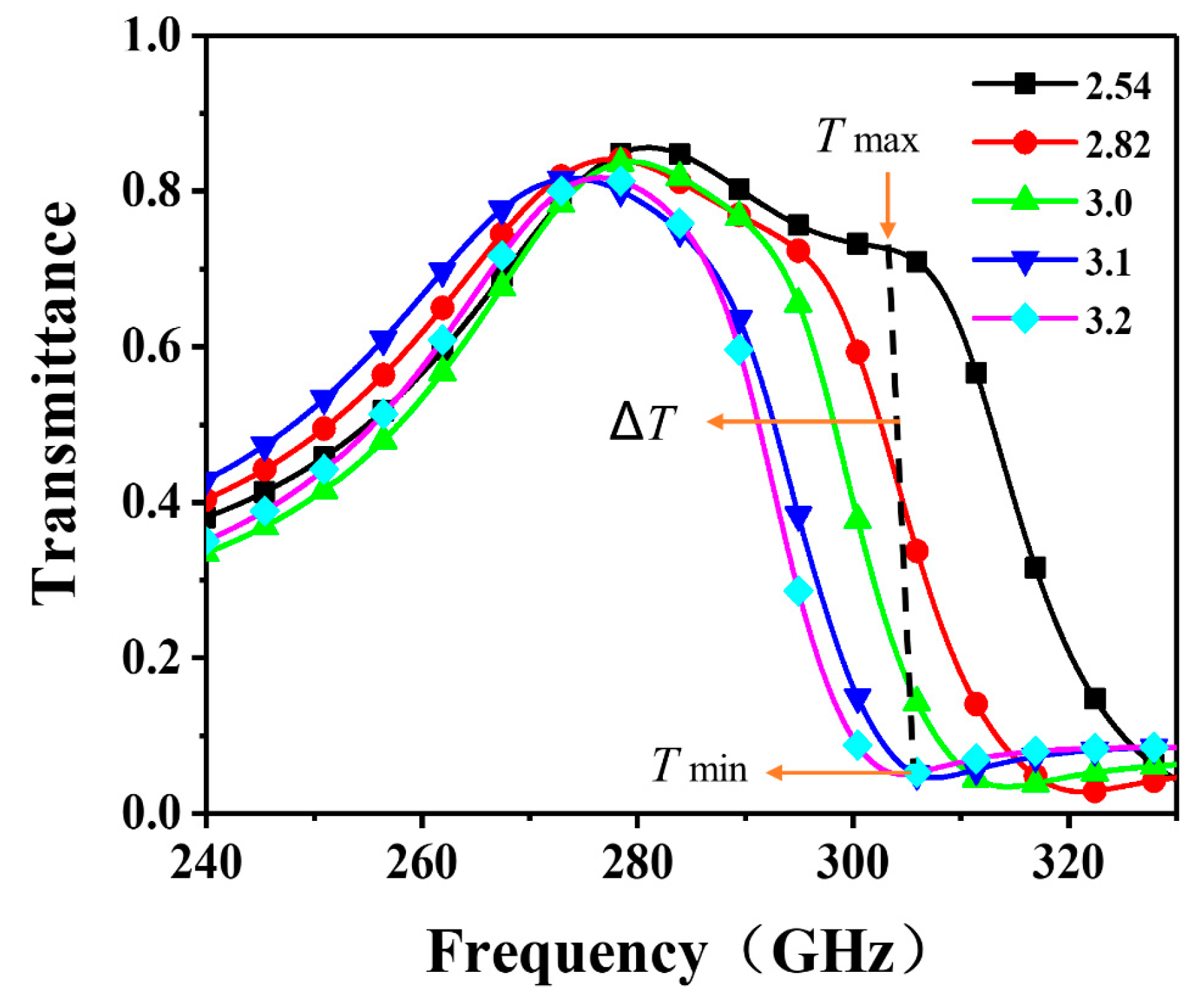
The transmittance spectrum can be changed to different NLC dielectric constants. The transmission characteristics and the LC parameters are calculated and analyzed for THz electromagnetic waves in the frequency range from 220 to 330 GHz. The EM performance of the LC-based MLM structure was analyzed and optimized using the finite difference time domain (FDTD) method. In the simulation, assuming that the unit cell is located in a periodic environment, and illuminated by a linear polarization and normal incidence plane wave. Period boundary conditions are used in the x-axis and y-axis directions, and the boundary condition in the z-axis direction is set to open. So, the EM properties of the THz MDM structure were obtained by FDTD. The simulated transmittance spectra of the modulator for different dielectric constants is shown in Figure 3.
Numerical results for resonant frequencies were obtained from the numerical FDTD, and fitted to the measured results. The conductivity of the copper layer was set to 5.8 × 10⁷ S/m. The dielectric constants are set from 2.54 to 3.2. The transmittance spectrum can be changed to different LC dielectric constants. As the dielectric constants increase, the lower transmittance spectrum will shift toward a low resonance frequency. This reveals that the LC-based MLM structure can change from its maximum to its minimum transmittance value.
The modulation depth (MD), insertion loss (IL), and ΔT are used to describe the performance of the LC-based modulator device. The MD, IL, and ΔT of the modulator structure at a frequency point can be calculated using:
ΔT = TmaxTmin,
MD = ΔT/Tmax,
IL = − 10 lg (Tmax),
Δφ = φmaxφmin,
where the parameters Tmax and Tmin are maximum and minimum transmittances of the structure at a certain frequency point. The variables φmax and φmin are the maximum and minimum phases of the structure at a certain frequency point, respectively.

4. Experimental Results and Discussions

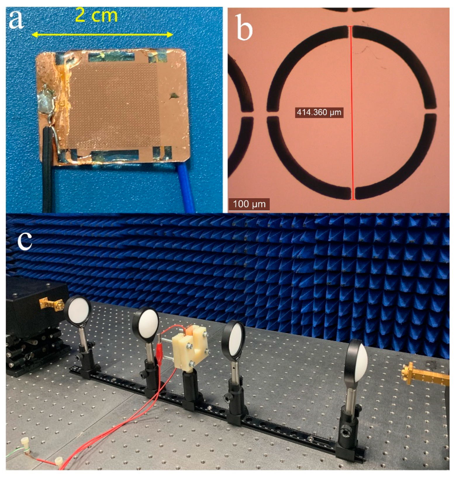
In order to experimentally verify the performance of the proposed device, the MLM structure was fabricated with a two-layer metal MM array using the ultraviolet lithography process. The manufactured device and the microscopic image of the unit cell are shown in Figure 3b and Figure 4a. The EM characteristics of the MLM structure were measured at room temperature using a vector network analyzer system and the transmission spectra were obtained at different bias voltages as shown in Figure 4c. The effective dielectric constant of the LCs molecules depends on the bias voltage. The Agilent N5224A vector network analyzer and the VDI mm-wave module extender (from 220 GHz to 325 GHz) were used to measure the transmittance spectra of the LC samples. Two pairs of lenses were used to focus the THz wave. The maximum voltage (20 V) with a 1 kHz square wave was applied to the patterned copper layer and the copper ground plane in the experiment.
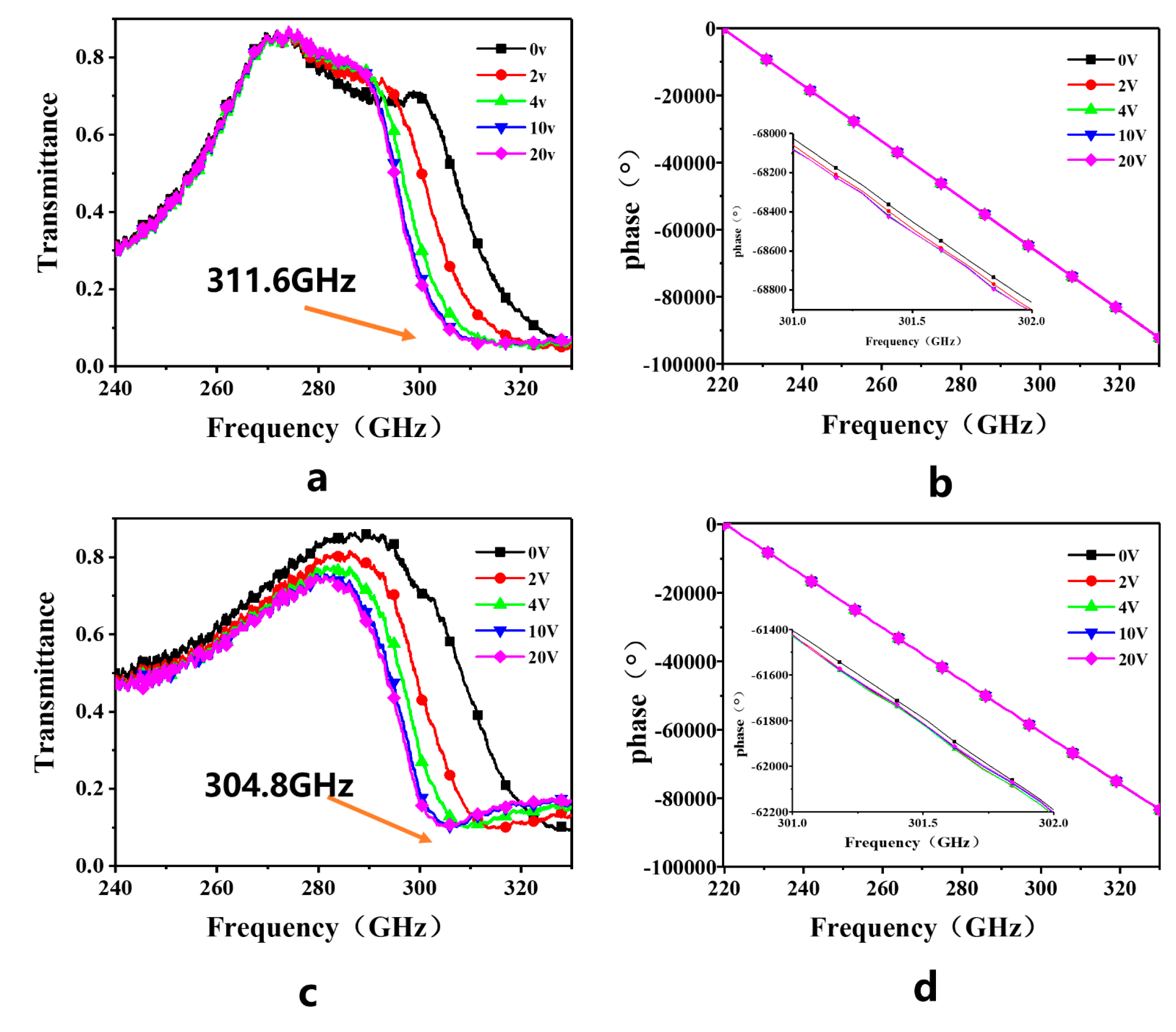
For applied voltages increasing from 0 V to 20 V, the transmission characteristics of the transmissive MLM structure are shown in Figure 4 and Figure 5, respectively. When the bias voltage is varied from 0 to 4 V, samples have rapid spectral transmittance changes. The transmittance of the samples slowly rises and eventually stabilizes when the bias voltage is higher than 4 V. For a zero applied bias voltage, the black curve (0 V) represents the maximum transmission spectrum. When the applied voltage increased to its maximum, the pink curve (20 V) is the minimum transmission spectra. The ΔT and MD values increase as the external applied bias is increased at a frequency point.
To further investigate the performance of the demonstrated sample at multiple frequency points, from Figure 5, we extracted the MD, IL, ΔT, and Δφ for specific frequency points. Table 2 lists the values for from frequencies ranging from 296 GHz to 312 GHz.
Compared to the resonance frequency point (311.6 GHz) of the low transmittance spectrum of the E7 LC characteristic shown in Figure 5a, the resonance frequency point of the E7-2 shift toward 304.8 GHz in Figure 5b, and the ΔT and MD values of the LC E7-2 are larger than that of the commercial LC E7 between 296 GHz and 305 GHz. The IL of the LC E7-2 sample is less than that of the commercial LC E7 from 296 GHz to 312 GHz. For example, the values of ΔT and MD of the LC E7-2 are 0.56 and 0.76 at 300 GHz, respectively, and ΔT and MD of the LC E7 are 0.47 and 0.69, respectively. The value of IL (1.51 dB) of the LC E7-2 sample is less than the IL (1.54 dB) of the commercial LC E7. These comparisons show that the dielectric anisotropy of mixture LC E7-2 is higher than that of commercial LC E7. The results indicate that mixture LC E7-2 can significantly increase the maximum transmission spectra of double-layer metal loop arrays’ modulation. The relative phases of E7 and E7-2 have a small change (Δφ < 90°) at different voltages.
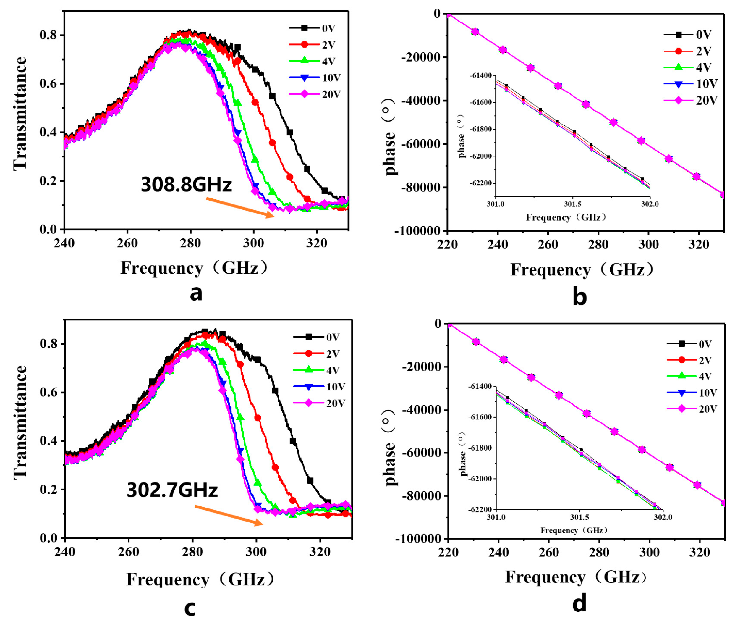
Figure 6 shows the transmission spectra results of NLC S200 and S200-2. These transmission spectra curves were measured for different voltages. The values of MD, IL, ΔT, and Δφ are listed in Table 3.
Compared to the resonance frequency point (308.8 GHz) of the low transmittance spectrum (the pink curve) of the S200 in Figure 6a, the resonant frequency point of the S200-2 shifts toward 302.7 GHz in Figure 6b. The ΔT and MD of the LC S200-2 mixture are larger than those of the commercial LC S200 from 296 GHz to 305 GHz. The IL of the LC S200-2 sample is less than that of the commercial LC S200. The phase of the S200 and S200-2 have small changes (Δφ < 90°) at different voltages in the working frequency band.
For example, the ΔT (0.6) and MD (0.83) of S200-2 are larger than the corresponding ΔT (0.49) and MD (0.75) values of the commercial LC S200 at 300 GHz. The IL (1.36 dB) of the LC S200-2 sample is less than the IL (2.2 dB) of the commercial LC S200 at 300 GHz. According to numerical FDTD simulation data, the values show that the dielectric anisotropy of the LC S200-2 mixture is higher than that of commercial LC S200.
These results indicate that the LC mixtures E7-2 and S200-2 can significantly increase the maximum transmission spectra of double-layer metal loop arrays’ modulation capabilities. The dielectric anisotropy of LC mixtures can be significantly increased by adding eight LC monomers. The birefringence these NLC materials exhibit high into the visible range would present comparatively high dielectric anisotropy in THz range as well.

5. Conclusions

In this paper, two new NLC mixtures (the LC S200-2 and the LC E7-2) were proposed and the birefringence of the nematic LC E7-2 and S200-2 mixtures is higher by 16.1% and 12.0% than the birefringence of the commercial LC products E7 and S200 at visible light, respectively. The eutectic mixtures (E7-2 and S200-2) have wide nematic phase temperature ranges. The values of ε//, Δɛ, K11, and K33 in eutectic mixtures are smaller than those of the commercial LCs E7 and S200 at 1 kHz. Based on the proposed LC and metamaterials, a THz MLM structure was fabricated to control terahertz waves using the ultraviolet lithography process. The experimental results are shown that LC mixtures E7-2 and S200-2 have larger ΔT, MD, and less IL for modulation than those E7 and S200 at THz frequencies for normal incidence of THz waves. The relative phases of LC mixtures have small change (Δφ < 90°) at different voltages. It also means that the Δɛ of the commercial liquid crystals (E7 and S200) is improved by adding eight LC monomers. Our work may provide an effective solution for the design of new high birefringence LC materials in the THz range.

Author Contributions

Original draft, fabricated, A.Z. and X.C.; designed, P.W. (Peng Wang); measurement, P.W. (Pengjun Wang) and S.G.; review and editing, J.Y.; resources, J.Y. and H.L.; methodology, G.D.; conceptualization, Z.Y. All authors have read and agreed to the published version of the manuscript.

Funding

This research is supported by the National Natural Science Foundation of China (Grant No. 61871171).

Conflicts of Interest

The authors declare no conflict of interest.

References

  1. Boulogeorgos, A.A.A.; Alexiou, A.; Merkle, T.; Schubert, C.; Elschner, R.; Katsiotis, A.; Stavrianos, P.; Kritharidis, D.; Chartsias, P.K.; Kokkoniemi, J.; et al. Terahertz Technologies to Deliver Optical Network Quality of Experience in Wireless Systems Beyond 5G. IEEE Commun. Mag. 2018, 56, 144–151. [Google Scholar] [CrossRef] [Green Version]
  2. Guerboukha, H.; Nallappan, K.; Skorobogatiy, M. Toward real-time terahertz imaging. Adv. Opt. Photonics 2018, 10, 843–938. [Google Scholar] [CrossRef]
  3. Yang, X.; Zhao, X.; Yang, K.; Liu, Y.P.; Liu, Y.; Fu, W.L.; Luo, Y. Biomedical Applications of Terahertz Spectroscopy and Imaging. Trends Biotechnol. 2016, 34, 810–824. [Google Scholar] [CrossRef] [PubMed]
  4. Liu, Y.; Liu, H.; Tang, M.Q.; Huang, J.Q.; Liu, W.; Dong, J.Y.; Chen, X.P.; Fu, W.L.; Zhang, Y. The medical application of terahertz technology in non-invasive detection of cells and tissues: Opportunities and challenges. RSC Adv. 2019, 9, 9354–9363. [Google Scholar] [CrossRef] [Green Version]
  5. Tian, L.L.; Chu, F.; Dou, H.; Li, L.; Wang, Q.H. Electrically Tunable-Focusing Liquid Crystal Microlens Array with Simple Electrode. Crystals 2019, 9, 431. [Google Scholar] [CrossRef] [Green Version]
  6. Wei, M.Q.; Zhang, D.N.; Li, Y.P.; Zhang, L.; Jin, L.C.; Wen, T.L.; Bai, F.M.; Zhang, H.W. High-Performance All-Optical Terahertz Modulator Based on Graphene/TiO2/Si Trilayer Heterojunctions. Nanoscale Res. Lett. 2019, 14, 1–6. [Google Scholar] [CrossRef]
  7. Wang, G.; Zhang, X.; Wei, X.; Zhang, G. Tunable and Polarization-Independent Plasmon-Induced Transparency in a Fourfold Symmetric Metal-Graphene Terahertz Metamaterial. Crystals 2019, 9, 632. [Google Scholar] [CrossRef] [Green Version]
  8. Zhou, G.C.; Dai, P.H.; Wu, J.B.; Jin, B.B.; Wen, Q.Y.; Zhu, G.H.; Shen, Z.; Zhang, C.H.; Kang, L.; Xu, W.W.; et al. Broadband and high modulation-depth THz modulator using low bias controlled VO2-integrated metasurface. Opt. Express 2017, 25, 17322–17328. [Google Scholar] [CrossRef]
  9. Zhao, Y.C.; Wang, L.; Zhang, Y.X.; Qiao, S.; Liang, S.X.; Zhou, T.C.; Zhang, X.L.; Guo, X.Q.; Feng, Z.H.; Lan, F.; et al. High-Speed Efficient Terahertz Modulation Based on Tunable Collective-Individual State Conversion within an Active 3 nm Two-Dimensional Electron Gas Metasurface. Nano Lett. 2019, 19, 7588–7597. [Google Scholar] [CrossRef]
  10. Shen, Z.X.; Zhou, S.H.; Ge, S.J.; Duan, W.; Ma, L.L.; Lu, Y.Q.; Hu, W. Liquid crystal tunable terahertz lens with spin-selected focusing property. Opt. Express 2019, 27, 8800–8807. [Google Scholar] [CrossRef]
  11. Kowerdziej, R.; Olifierczuk, M.; Parka, J.; Wrobel, J. Terahertz characterization of tunable metamaterial based on electrically controlled nematic liquid crystal. Appl. Phys. Lett. 2014, 105, 022908. [Google Scholar] [CrossRef]
  12. Kowerdziej, R.; Jaroszewicz, L.; Olifierczuk, M.; Parka, J. Experimental study on terahertz metamaterial embedded in nematic liquid crystal. Appl. Phys. Lett. 2015, 106, 092905. [Google Scholar] [CrossRef]
  13. Li, J.; Chu, D. Liquid Crystal-Based Enclosed Coplanar Waveguide Phase Shifter for 54–66 GHz Applications. Crystals 2019, 9, 650. [Google Scholar] [CrossRef] [Green Version]
  14. Duan, W.; Chen, P.; Ge, S.J.; Liang, X.; Hu, W. A Fast-Response and Helicity-Dependent Lens Enabled by Micro-Patterned Dual-Frequency Liquid Crystals. Crystals 2019, 9, 111. [Google Scholar] [CrossRef] [Green Version]
  15. Wang, J.; Tian, H.; Wang, Y.; Li, X.Y.; Cao, Y.J.; Li, L.; Liu, J.L.; Zhou, Z.X. Liquid crystal terahertz modulator with plasmon-induced transparency metamaterial. Opt. Express 2018, 26, 5769–5776. [Google Scholar] [CrossRef]
  16. Yan, D.X.; Li, J.S.; Jin, L.F. Light-controlled tunable terahertz filters based on photoresponsive liquid crystals. Laser Phys. 2019, 29, 025401. [Google Scholar] [CrossRef]
  17. Yang, J.; Xia, T.Y.; Jing, S.C.; Deng, G.S.; Lu, H.B.; Fang, Y.; Yin, Z.P. Electrically Tunable Reflective Terahertz Phase Shifter Based on Liquid Crystal. J. Infrared Millim. Terahertz Waves 2018, 39, 439–446. [Google Scholar] [CrossRef]
  18. Du, Y.; Tian, H.; Cui, X.; Wang, H.; Zhou, Z.X. Electrically tunable liquid crystal terahertz phase shifter driven by transparent polymer electrodes. J. Mater. Chem. C 2016, 4, 4138–4142. [Google Scholar] [CrossRef]
  19. Yuan, Y.H.; He, J.A.; Liu, J.S.; Yao, J.Q. Electrically controlled broadband THz switch based on liquid-crystal-filled multi-layer metallic grating structures. J. Phys. Conf. Ser. 2011, 276. [Google Scholar] [CrossRef]
  20. Wang, R.X.; Li, L.; Liu, J.L.; Yan, F.; Tian, F.J.; Tian, H.; Zhang, J.Z.; Sun, W.M. Triple-band tunable perfect terahertz metamaterial absorber with liquid crystal. Opt. Express 2017, 25, 32280–32289. [Google Scholar] [CrossRef]
  21. Ge, S.J.; Chen, P.; Shen, Z.X.; Sun, W.F.; Wang, X.K.; Hu, W.; Zhang, Y.; Lu, Y.Q. Terahertz vortex beam generator based on a photopatterned large birefringence liquid crystal. Opt. Express 2017, 25, 12349–12356. [Google Scholar] [CrossRef] [PubMed] [Green Version]
  22. Li, X.F.; Tan, N.; Pivnenko, M.; Sibik, J.; Zeitler, J.A.; Chu, D.P. High-birefringence nematic liquid crystal for broadband THz applications. Liq. Cryst. 2016, 43, 955–962. [Google Scholar] [CrossRef] [Green Version]
  23. Vieweg, N.; Jansen, C.; Shakfa, M.K.; Scheller, M.; Krumbholz, N.; Wilk, R.; Mikulics, M.; Koch, M. Molecular properties of liquid crystals in the terahertz frequency range. Opt. Express 2010, 18, 6097–6107. [Google Scholar] [CrossRef] [PubMed]
  24. Vieweg, N.; Shakfa, M.K.; Koch, M. BL037: A nematic mixture with high terahertz birefringence. Opt. Commun. 2011, 284, 1887–1889. [Google Scholar] [CrossRef]
  25. Wang, L.; Lin, X.W.; Liang, X.; Wu, J.B.; Hu, W.; Zheng, Z.G.; Jin, B.B.; Qin, Y.Q.; Lu, Y.Q. Large birefringence liquid crystal material in terahertz range. Opt. Mater. Express 2012, 2, 1314–1319. [Google Scholar] [CrossRef]
  26. Reuter, M.; Vieweg, N.; Fischer, B.M.; Mikulicz, M.; Koch, M.; Garbat, K.; Dąbrowski, R. Highly birefringent, low-loss liquid crystals for terahertz applications. APL Mater. 2013, 1, 012107. [Google Scholar] [CrossRef]
  27. Zheng, A.D.; Xia, X.; Gao, S.; Yang, J.; Lu, H.B.; Deng, G.S.; Yin, Z.P. Dielectric properties of two high birefringence liquid crystal mixtures in the Sub-THz band. Liq. Cryst. 2019, 47. [Google Scholar] [CrossRef]
  28. Yang, J.; Wang, P.; Shi, T.; Gao, S.; Lu, H.B.; Yin, Z.P.; Lai, W.E.; Deng, G.S. Electrically tunable liquid crystal terahertz device based on double-layer plasmonic metamaterial. Opt. Express 2019, 27, 27039–27045. [Google Scholar] [CrossRef]
  29. Lapanik, V.; Sasnouski, G.; Timofeev, S.; Shepeleva, E.; Evtyushkin, G.; Haase, W. New highly anisotropic liquid crystal materials for high-frequency applications. Liq. Cryst. 2018, 45, 1242–1249. [Google Scholar] [CrossRef]
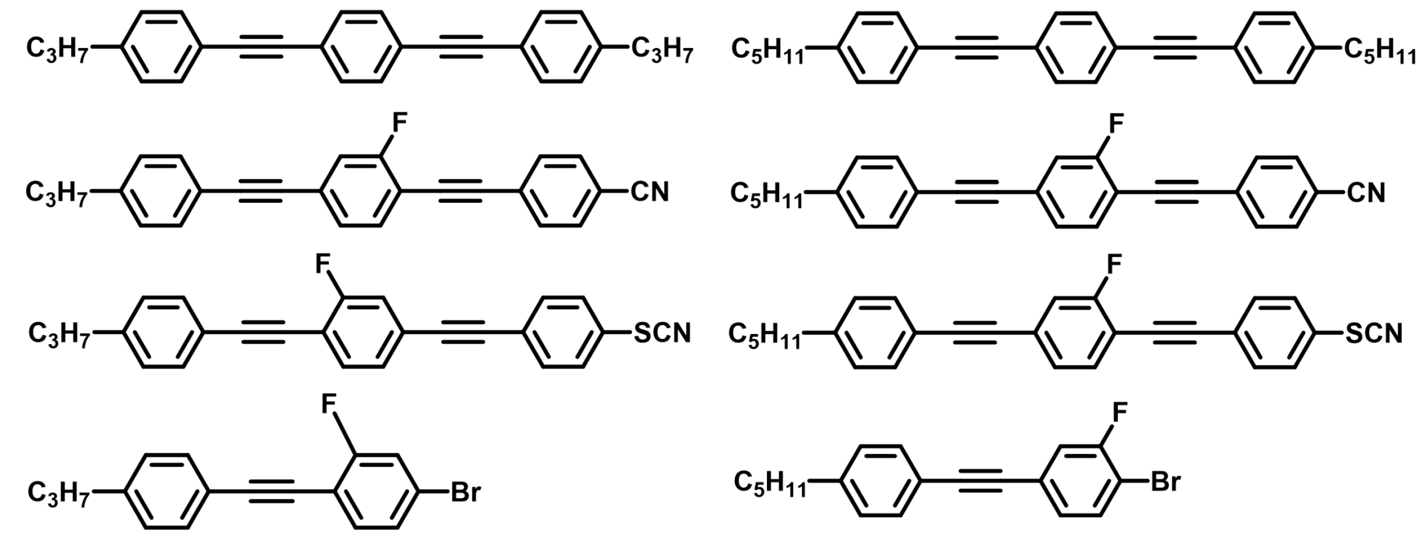
Figure 1. Chemical structures of the eight liquid crystal (LC) monomers.
Crystals 10 00099 g001
Figure 2. (a) The unit cell structure. (b) Layout of the unit cell structure of the copper pattern. (c) Orientation of the LC molecules with different electric fields. (d,e) Side view orientation of the LC molecules for biased and unbiased states.
Crystals 10 00099 g002
Figure 3. Simulated transmittance spectra for different dielectric constants.
Crystals 10 00099 g003
Figure 4. The photograph of sample and schematics of the experimental setup. (a) Fabricated sample structure (20 × 20 mm2). (b) A polarized microscope image of a single unit cell. (c) Experimental measurement setup.
Crystals 10 00099 g004
Figure 5. (a) Transmission spectra of the LC E7 sample. (b) Phase information of the LC E7 sample. (c) Transmission spectra of the LC E7-2 sample. (d) Phase information about the LC E7-2 sample.
Crystals 10 00099 g005
Figure 6. (a) LC S200 sample transmission spectra. (b) LC S200 sample phase information. (c) LC S200-2 sample transmission spectra. (d) LC S200-2 sample phase information.
Crystals 10 00099 g006
Table 1. Physical properties of nematic liquid crystals (NLCs) E7, E7-2, and S200 and S200-2.
LCnoΔnTN-I (°C)ε//ΔɛK11(PN)K33(PN)
E71.5170.22458.216.711.17.218.1
E7-21.5220.26072.215.410.17.111.3
S2001.5150.266101.119.814.98.412.3
S200-21.5160.298114.916.013.07.13.9
Table 2. Comparison of two LC samples (E7 and E7-2) at certain frequency points.
Frequency (GHz)ΔTMDIL (dB)Δφ (°)
2960.27 < 0.420.39 < 0.531.65 > 1.0169.1 : 46.5
2970.35 < 0.450.50 < 0.581.50 > 1.1554.9 : 46.5
3000.47 < 0.560.69 < 0.761.54 > 1.5159.5 : 25.5
3030.49 < 0.550.78 < 0.831.94 > 1.7046.0 : −4.7
3050.45 < 0.510.81 < 0.842.52 > 2.0814.8 : −10.8
3060.44 < 0.480.83 > 0.810.26 > 0.2924.2 : −34.3
3070.40 < 0.430.82 > 0.790.31 > 2.691.70 : −39.5
3120.23 > 0.250.77 > 0.615.38 > 4.50−42.0 : −80.0
Table 3. Comparison of two LC samples (S200 and S200-2) at certain frequency points.
Frequency (GHz)ΔTMDIL (dB)Δφ (°)
2960.40 < 0.520.56 < 0.671.94 >1.2059.6 : 39.2
2970.42 < 0.550.61 < 0.722.05 > 1.2340.8 : 36.1
3000.47 < 0.560.69 < 0.761.54 > 1.5130.7 : 20.8
3030.49 < 0.550.78 < 0.831.94 > 1.702.2 : −10.7
3050.45 < 0.510.81 < 0.842.52 > 2.0819.3 : −16.9
3060.44 < 0.480.83 > 0.810.26 > 0.29−10.6 : −31.3
3100.40 < 0.430.82. > 0.790.31 > 2.69−74.3 : −82.5
3120.23 > 0.250.77 > 0.615.38 > 4.50−56.8 : −65.4