Abstract
Exploring efficient non-precious metal based electrocatalysts for the oxygen evolution reaction (OER) is a prerequisite to implement the widespread application of a water electrolyzer and metal-air batteries. Herein, Fe-doped NiS2 nanoparticles on a carbon matrix (Fe-NiS2/C) are facilely prepared via a two-step solvothermal process, where Ni-containing metal organic frameworks (Ni-MOFs) are vulcanized in situ and carbonized by a solvothermal method to form abundant NiS2 nanoparticles homogeneously distributed on a carbon matrix (NiS2/C), followed by doping with ferric ions via a similar solvothermal treatment. The resulting Fe-NiS2/C nanoparticle composites show a rougher surface than the NiS2/C parent, likely due to the formation of more structural defects after ferric ion doping, which maximizes the exposure of active sites. Moreover, ferric ion doping can also regulate the surface electronic state to reduce the activation energy barrier for OER on NiS2/C sample. With these merits, the best sample Fe-NiS2/C-30 only requires a potential of +1.486 V (vs. RHE) to reach an OER current density of 10 mA cm−2 and can retain 96.85% of its initial current after continuous working for about 10 h in 1.0 M KOH aqueous solution, along with a small Tafel slope of 45.66 mV/dec, outperforming a commercial RuO2 catalyst. The results in this work enrich the method to tailor the catalytic activity of transition metal sulfides for electrochemical energy technologies.
1. Introduction
Exploring green and sustainable energy is a viable way to alleviate/solve the current predicaments encountered in fossil fuels, i.e., the very limited reserve in the Earth’s crust as well as the associated environmental issues resulting from inefficient utilization. However, the intermittent availability of some important green and sustainable energies, such as wind, solar, and tidal energy, severely impedes their widespread applications [1,2], which requires exploration and combinative utilization of efficient cost-effective energy storage and conversion systems. Water electrolyzers and metal-air batteries represent two promising electrochemical energy conversion and storage technologies, both of which involve the OER process [3]. Note that the oxygen evolution reaction (OER) is a four-electron process with multiple consecutive step reactions [4], and its complex process and sluggish kinetics largely determine the efficiency of these two electrochemical energy technologies [5]. To ensure a sufficient high current density for practical applications, highly efficient OER electrocatalysts are generally required. So far, the precious metal catalysts, normally Ir- or Ru-based nanostructured oxides, are the common choices due to their remarkable OER catalytic activities. Yet, the shortcomings of precious metals, including scarcity, high cost, and rapid deactivation during operation, call for efficient alternatives which are abundant in the Earth’s crust and cost-effective.
Over the past few decades, several catalyst materials have been screened out as the potential alternatives to the conventional precious metals-based OER catalysts, including various heteroatom-doped carbons [6] and transition metal sulfides [7,8,9], oxides [10,11,12,13], nitrides [14], borides [15], phosphides or phosphates [16], and also hydroxides or double hydroxides [17]. Therein, various nanostructured nickel compounds have attracted considerable research attention. For instance, Anantharaj et al. [18] reported a petal-like hierarchical array of ultrathin Ni(OH)2 nanosheets which showed an overpotential of 300 mV at 10 mA cm−2. Lou’s group [19] used an anisotropic chemical etching assisted route to synthesize cubic nanocage-liked Ni-Co-mixed oxides that exhibited enhanced OER activity and good durability in an alkaline medium. Xu and co-workers [20] found that Ni nanoparticles encapsulated by ultrathin N-doped graphitized carbon layers that were facilely prepared through direct pyrolysis of Ni-containing metal-organic frameworks (Ni-MOFs) were able to serve as efficient bifunctional electrocatalysts for overall water splitting. As a typical member of the large family of metal sulfides, nickel sulfides are considered to be cost-effective candidates for efficient OER catalysis. Yet, the reported OER catalytic activities for pristine nickel sulfides vary in a wide range, in terms of the overpotentials at 10 mA cm−2 [21,22,23], which may cause missing potential ones during sample screening. Therefore, exploring novel and facile routes to tailor the OER catalytic activities of nickel sulfides are still highly demanded.
Herein, NiS2 nanoparticles were facilely prepared by solvothermally treating the Ni-MOFs with the presence of organosulfur, and then doped with ferric ions also by a similar solvothermal process. After doping, the surface of NiS2 nanoparticles becomes rougher, probably due to the formation of more structural defects, which maximize the electrochemical surface area (ECSA) so that the active sites are sufficiently exposed. Concurrently, the surface electronic structure is regulated and lower activation energy is required for OER, which finally leads to an enhanced OER activity, with the best one featuring a required potential of only +1.486 V (vs. RHE) to reach an electrode current density of 10 mA cm−2, as well as a high working stability.
2. Results and Discussion
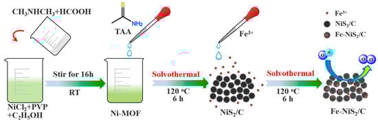
The synthesis process of a series of Fe-NiS2/C-X samples was schematically illustrated in Scheme 1, where NiS2/C composite nanoparticles were firstly synthesized by in situ vulcanization and carbonization of the Ni-containing MOF nanoparticles via a solvothermal method [24], while a secondary solvothermal treatment subsequently doped ferric ions into the crystalline lattices of NiS2.
Scheme 1.
Schematic illustration of the preparation of Fe-NiS2/C samples.
As for the precursor Ni-MOFs, i.e., [CH3CH3NH2][Ni(HCOO)3], they are crystalline (Figure S1) and show a spindle-like particle morphology, with a predominant length in the range of 100–500 nm (Figure 1a and Figure S2a,b). After solvothermal treatment in the presence of TAA at 120 °C for 6 h, Ni-MOFs were carbonized and concurrently vulcanized, leading to a composite of NiS2 and carbon, i.e., NiS2/C (Figure 1b), with a particle morphology resembling to the parent Ni-MOFs. Further doping NiS2/C with ferric ions through a secondary solvothermal treatment makes the NiS2/C composite nanoparticles become rougher (Figure 1c,d), without an apparent change to the size of the nanoparticles (Figure S2c,d). From the corresponding XRD profiles depicted in Figure 2, one can find that after the first solvothermal treatment, the resulting NiS2/C sample shows distinct peaks at 2θ = 31.4°, 35.3°, 38.8°, 45.1°, 53.4°, 58.5°, and 60.9°, corresponding to the (200), (0–12), (−1–12), (–202), (−1–31), (−2–22), (−320), and (2–31) planes of triclinic phase NiS2 (JCPDS no. 73-0574). These observations signify that solvothermal treatment in the presence of TAA successfully vulcanizes the Ni-MOFs, and leads to the formation of phase-pure triclinic NiS2. After a secondary solvothermal treatment in the presence of FeCl3, Fe was indeed doped into the lattices of triclinic phase NiS2, as supported by the observation of the Fe signal in the EDS measurements (Figure S3). Meanwhile, one can find that he introduction of Fe, herein 30 wt% in the precursor, causes no apparent change to the crystalline phase probably due to that the atomic radius of Fe3+ (0.055 nm) is close to that of Ni2+ (0.069 nm) [7,25,26], as signified by the results that the corresponding XRD peaks in both Fe-NiS2/C-30 and NiS2/C samples appeared at identical positions (Figure 2). After careful comparison, it is found that the crystallinity of NiS2 phase in Fe-NiS2/C-30 is obviously higher than that in NiS2/C sample, probably due to the double solvothermal treatments, i.e., longer solvothermal treatment time for NiS2 crystallization.
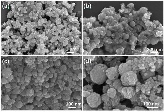
Figure 1.
SEM images of (a) Ni-MOFs; (b) NiS2/C; (c,d) Fe-NiS2/C-30.
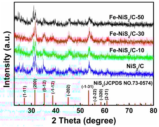
Figure 2.
XRD profiles for different investigated samples.
From the corresponding TEM image for Fe-NiS2/C-30 depicted in Figure 3a, the dark-contrast domains with a diameter of 100 to 200 nm are comprised with many tiny nanoparticles ranging from several nanometers to about 20 nm, and similar observations are observed for Fe-NiS2/C-10 (Figure S4c) and Fe-NiS2/C-50 samples (Figure S4e). HR-TEM measurements were conducted to gain further insights into the detailed morphology and crystalline structures. As shown in Figure 3b, well-defined lattice fringes with d-spacings of 0.332, 0.292, 0.252, and 0.233 nm are observed, corresponding to the (1–11), (200), (0–12), and (−1–12) facets of triclinic phase NiS2, respectively, which coincide with the XRD results. Interestingly, although the amount of FeCl3 was varied between 0 and 50 wt% in the precursors, the crystalline triclinic phase NiS2 was retained (Figure 2, Figure S4), again indicating that incorporation of Fe3+ into the lattices of NiS2 causes no apparent change to the crystalline structure. From the series elemental mapping images depicted in Figure 3c, one can find that the distributions of C, N, O, S, Ni, and Fe are quite homogeneous and resemble to each other, signifying the formation of homogeneously-distributed NiS2 supported on carbonized MOFs matrix, i.e., Fe-NiS2/C.
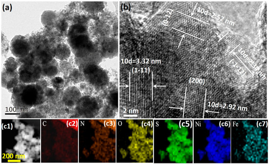
Figure 3.
(a) The TEM, (b) HR-TEM, and (c) the corresponding elemental mapping images of the Fe-NiS2/C-30 sample.
The N2 adsorption-desorption isotherms of NiS2/C and Fe-NiS2/C-30 are shown in Figure 4, and one can find that they are type IV isotherms with a well-developed H3-type hysteresis loop (P/P0 > 0.4). The initial part (0 < P/P0 < 0.4) of the type IV isotherm is attributed to monolayer-multilayer adsorption and the hysteresis appearing in the multilayer range of physisorption isotherms is usually associated with capillary condensation in pore structures [27,28]. The BET specific surface area was evaluated to be 107 m2 g−1 for NiS2/C (Figure 4a), 141 m2 g−1 for Fe-NiS2/C-10 (Figure S5a), 150 m2 g−1 for Fe-NiS2/C-50 (Figure S5b) and 158 m2 g−1 for Fe-NiS2/C-30 (Figure 4b), respectively. The corresponding pore diameter distribution plots were inset to each panel in Figure 4 and Figure S5, where one can find that NiS2/C and Fe-NiS2/C-X samples consist of hierarchical pore structures, with both micropores (< 2.0 nm) and mesopores of 2.0~10.0 nm. As is well documented, mesopores are beneficial to the mass/ions diffusion and transport process and, hence, the presence of abundant mesopores may improve the electrochemical reaction kinetics [24]. It is evident that the introduction of Fe to the lattices of NiS2 can enhance the specific surface area, and it is most likely that the introduction of heteroatom Fe to the lattices of NiS2 causes structural defects although the radius of Fe3+ close to that of Ni2+ [29] and, hence, impedes the growth of large-scale NiS2 crystals, which finally leads to an increased surface roughness for Fe-NiS2/C-30 (Figure 1c,d), as compared with NiS2/C (Figure 1b). This is supported by the results from Figure 1c,d, where although the crystallinity of NiS2 in Fe-NiS2/C-30 sample is much higher than that in NiS2/C sample (Figure 2), their crystalline domain sizes are highly comparable (Figure 1b,c). Note that the specific surface area is closely correlated to the electrochemically surface area (ECSA). A large specific surface area can maximize the exposure of active components for better catalytic activity.
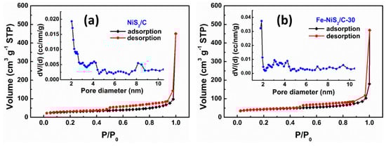
Figure 4.
N2 adsorption-desorption isotherms for (a) NiS2/C, and (b) Fe-NiS2/C-30. Inset in each panel is the corresponding pore diameter distribution plot.
In order to further investigate the surface composition and chemical states of the Fe-NiS2/C-30 sample, XPS measurements were carried out. Figure 5a and Figure S6b–d show the survey spectra for Fe-NiS2/C-X samples, where elements Ni, Fe, S, C, N, and O can be resolved. The high-resolution spectrum of Fe 2p (Figure 5b) exhibits two pairs of pronounced peaks at about 712.6 ± 0.2 and 724.3 ± 0.1 eV, corresponding to the Fe 2p1/2 and Fe 2p3/2 signals [30], respectively, while the ones at about 717.4 ± 0.1 and 732.4 ± 0.2 eV are the shakeup satellite peaks. Moreover, the two peaks at about 712.6 ± 0.1 and 725.3 eV ± 0.2 are derived from Fe3+, hence their appearance manifest that most Fe in the Fe-NiS2/C-30 sample presents in the form of Fe3+. Again, owing to the close ionic radius of Fe3+ (0.055 nm) and Ni2+ (0.069 nm), ferric ion doping will not obviously change the lattice structure of NiS2 [31].
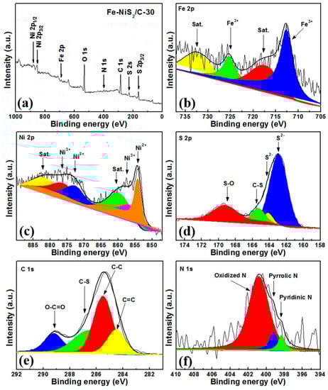
Figure 5.
XPS (a) survey spectra and high-resolution spectra of (b) Fe 2p, (c) Ni 2p, (d) S 2p, (e) C 1s, and (f) N 1s for the Fe-NiS2/C-30 sample.
For the high-resolution Ni 2p spectrum (Figure 5c), deconvolution yields two pairs of spin-orbit doublets for Ni 2p3/2 (854.2 ± 0.1, 856.1 ± 0.2 eV) and Ni 2p1/2 (872.6 ± 0.2, 875.9 ± 0.1 eV) [15], while the two peaks at about 859.6 ± 0.1 and 881.9 ± 0.1 eV are ascribed to the satellite peaks of NiO [32]. However, in the corresponding XRD and HR-TEM measurements, no crystalline phase of NiO is observed, indicative of the amorphous nature of NiO in present work. Specifically, the two peaks at around 872.6 ± 0.2 and 854.2 ± 0.1 eV are attributed to the Ni 2p1/2 and Ni 2p3/2 of Ni2+ species, respectively. Accordingly, the other two peaks at about 875.9 ± 0.1 and 856.1 ± 0.2 eV are attributed to the Ni 2p1/2 and Ni 2p3/2 of Ni3+ species, respectively. These results signify the presence of Ni2+ and Ni3+ and indicate the formation of NiS2 at the same time. The existence of Ni3+ is mainly due to the presence of surface oxidation after long-term exposure to air.
The S 2p spectrum is shown in Figure 5d. The peaks located at 162.9 ± 0.1 and 164.1 ± 0.2 eV are attributed to the S 2p3/2 and S 2p1/2 for S2− species in NiS2, while the other two peaks at around 165.3 ± 0.2 and 169.2 ± 0.2 eV, are attributed to C-S species and Ni-O-S species resulting from surface oxidation, respectively.
The spectrum of C 1s (Figure 5e) can be deconvoluted into four peaks at about 289.2 ± 0.2, 286.5 ± 0.2, 285.7 ± 0.1 and 284.5 ± 0.2 eV, corresponding to O-C=O, C-S, C-C, and C=C species [33], respectively. The chemical states of nitrogen is also probed by XPS measurements. As depicted in Figure 5f, deconvoluted peaks at about 398.3 ± 0.1, 399.1 ± 0.2, and 400.8 ± 0.1 eV are resolved, which are attributed to the pyridinic N, pyrrolic N, and oxidized N, respectively [34]. The lack of graphitic N is mainly because that the solvothermal treatment was conducted at a relatively low temperature of 120 °C. Since the dominant nitrogen doping configuration in Fe-NiS2/C-30 is oxidized N that is nonactive for oxygen electrocatalysis, the carbonized matrix may only serve as a conductive support for homogeneously distributing the tiny NiS2 nanoparticles. The detailed elemental compositions and specific surface area, as well as the pore structures of the series Fe-NiS2/C-X samples, are summarized in Table 1. The contents of different nitrogen doping configurations for the samples are listed in Table S1.

Table 1.
Summary of the BET specific surface area, pore size and surface compositions of catalysts determined by XPS.
The OER performance for the above series samples were evaluated in O2-saturated alkaline medium (1.0 M KOH) with a typical three-electrode cell setup. For comparison, commercial RuO2 was also investigated under the identical experimental conditions. To mitigate the iR loss from electrolyte resistance, the LSV curves were corrected on the basis of electrical impedance spectroscopy. As shown in Figure 6a, when the potential is positively swept from +1.300 V to +1.800 V (vs. RHE), the anodic current rapidly increases for all the investigated samples, suggesting the appearance of OER. As for Fe-NiS2/C-30, a potential of +1.486 V (vs. RHE) is required to reach a current density of 10 mA cm−2, which is much lower than the +1.594 V (vs. RHE) for NiS2/C, +1.526 V (vs. RHE) for Fe-NiS2/C-10, +1.611 V (vs. RHE) for Fe-NiS2/C-50, as well as +1.550 V (vs. RHE) for commercial RuO2 catalyst. These observations suggest that the Fe-NiS2/C-30 sample shows the best OER catalytic activity among the series.
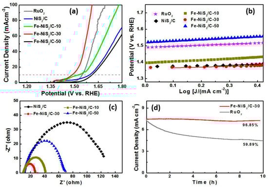
Figure 6.
(a) The LSV curves for different samples measured in 1.0 M KOH aqueous solution, and the corresponding (b) Tafel plots and (c) (EIS plots. (d) Chronoamperometric plots of Fe-NiS2/C-30 and commercial RuO2 at +1.540 V for comparing their long-term stability.
The OER process usually involves multiple electron reactions. Those reactions include either electron transfer steps (i.e., four sequential proton-coupled electron transfer steps) or chemical steps, such as dissociation reactions (H-O bond fracture). To analyze the OER kinetics, the Tafel plots for the above investigated samples are acquired according to the following Equation (1):
where j is the current density and b is the Tafel slope. Normally, in a consecutive reaction, the Tafel slopes are utilized to discriminate the rate-determining steps. When a Tafel slope is about 120 mV/dec, the rate-determining step is governed by the electron transfer process; and a Tafel slope of about 60 mV/dec signifies that the chemical step serves as the corresponding rate-determining step. Similarly, when the Tafel slope is about 40 mV/dec, the rate-determining step is an electron-proton reaction, while a smaller Tafel slope suggest that the rate-determining step is at the ending part of multiple-electron transfer reaction. Therefore, one can conclude that a smaller Tafel slope might suggest a faster kinetics and a higher OER catalytic activity. From Figure 6b, the Tafel slope for Fe-NiS2/C-30 is determined to be 45.66 mV/dec, which is much lower than NiS2/C (82.22 mV/dec), Fe-NiS2/C-10 (87.20 mV/dec), and Fe-NiS2/C-50 (87.18 mV/dec), and even the commercial RuO2 (65.53 mV/dec). These results signify that Fe-NiS2/C-30 shows the fastest OER kinetics among the series, which is highly consistent with the results from LSV measurements (Figure 6a).
η = b log (j) + a
To better understand the OER mechanism, EIS for the above series samples is measured. Normally, a smaller resistance indicates a higher conductivity and a lower activation energy. As depicted in Figure 6c, the NiS2/C sample shows a semicircle with a diameter of 125.44 Ω. After doping with ferric ions, the diameter of semicircle is markedly reduced to 32.29 Ω for Fe-NiS2/C-10, 16.27 Ω for Fe-NiS2/C-30, and 59.87 Ω for Fe-NiS2/C-50, which suggests that the introduction of ferric ions to NiS2/C can substantially enhance the electronic conductivity and OER kinetics, most probably due to the formation of more structural defects and regulation of the surface electronic structure after ferric ion doping. Moreover, these results signify that the activation energy of OER is the lowest on Fe-NiS2/C-30 sample among all the investigated samples, which coincides with their OER catalytic activities depicted in Figure 6a. Taking all the above observations into account, the catalytic activities of the Fe-NiS2/C-30 sample is better than, or at the least comparable to, the leading Ni-based OER catalyst recently reported in literature (Table 2).
Table 2.
Summary of the key OER catalytic parameters of the series samples in this work and some recently reported Ni-based OER electrocatalysts in 1.0 M KOH.
The stability of the above most active sample Fe-NiS2/C-30 and commercial RuO2 catalyst was investigated by chronoamperometric measurements at a fixed potential of +1.540 V (vs. RHE). As depicted in Figure 6d, after continuous working for about 10 h, the Fe-NiS2/C-30 modified electrode can maintain 96.85% of its initial current. In sharp contrast, the state-of-the-art RuO2 catalyst modified electrode can only retain 59.89% of its initial current under the same working conditions. These results clearly signify that Fe-NiS2/C-30 shows a much higher working stability than the commercial RuO2 catalyst.
The impacts of ferric ion doping on the ECSA for the series of Fe-NiS2/C-X samples was evaluated by measuring the capacitive current associated with the charging/discharging process of electrostatic double layer at varied potential scan rates (i.e., 20, 60, 100, 140, and 180 mV s−1 as depicted in Figure 7a and Figure S8). From the plots of current difference (ΔJ = ja − jc at +0.650 V, vs. RHE) against scan rates shown in Figure 7b, one can find that without ferric ion doping, the NiS2/C sample shows a Cdl (capacitance of the electrostatic double layer) of 1.38 mF cm−2. After doping, the Cdl value is increased to 1.53 mF cm−2 for Fe-NiS2/C-10, and 1.69 mF cm−2 for Fe-NiS2/C-30. These observations signify that ferric ion doping can effectively improve the ECSA of NiS2/C samples and finally contributes to an enhanced OER activity. However, It is worthy to note that doping with excessive ferric ions can block the active sites as supported by a decreased Cdl value for Fe-NiS2/C-50 (1.35 mF cm−2), which results in a decrease in OER activity.
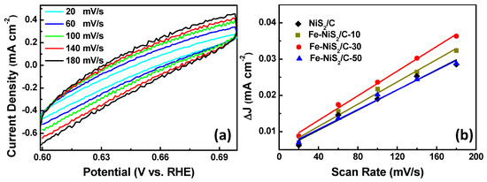
Figure 7.
(a) Cyclic voltammograms recorded within the potential range of +0.600–0.700 V (vs. RHE) for the Fe-NiS2/C-30 sample. (b) The plots of current density difference (ΔJ = ja − jc) at +0.650 V (vs. RHE) against the potential scan rate. The linear curves are the corresponding linear fittings for evaluating Cdl.
3. Experimental Section
3.1. Chemicals and Reagents
All chemicals in this work were of analytical-reagent grade and used as received without further purification. Nickel chloride hexahydrate (NiCl2·6H2O), ferric chloride hexahydrate (FeCl3·6H2O), ethanediol (C2H6O2), formic acid (HCOOH, 88%), ethanol (C2H5OH), dimethylamine ((CH3)2NH, 40%), polyvinylpyrrolidone (PVP K-30), thioacetamide (TAA, CH3CSNH2), potassium hydroxide (KOH) were purchased from Shanghai Macklin Biochemical Co., Ltd. (Shanghai, China) Ruthenic oxide (RuO2) was obtained from Aladdin Ltd. (Shanghai, China).
3.2. Synthesis
3.2.1. Synthesis of Ni-MOFs
The Ni-MOF precursor was prepared according to the method reported elsewhere. The synthesis process is depicted in Scheme 1, where in a typical synthesis, 0.5 mL HCOOH, 1.0 mL (CH3)2NH, and 0.5 g PVP K-30 were dissolved in 25.0 mL ethanol to form a homogeneous solution, followed by the addition of 25.0 mL ethanol solution containing 1.0 mmol of NiCl2·6H2O and 0.5 g PVP K-30. Subsequently, the mixture was stirred overnight. The solid was obtained by filtration, followed by washing with ethanol for several times and vacuum drying at 35.0 °C overnight.
3.2.2. Synthesis of NiS2 and Fe-NiS2/C-X
NiS2 nanoparticles were synthesized via a simple solvothermal method and Fe was subsequently doped into NiS2 nanoparticles by a secondary solvothermal process, as depicted in Scheme 1. Briefly, 30.0 mg of the Ni-MOF and 20.0 mg of TAA were dispersed in 40.0 mL ethanol by sonication for 10.0 min. The obtained light green solution was then transferred into a 50.0 mL Teflon-lined autoclave and maintained at 120 °C for 6 h. The black precipitate was obtained after washing with deionized water and ethanol for several times. Afterwards, 20.0 mg mixture of FeCl3·6H2O and NiS2 was added to 40.0 mL ethanediol to form a homogeneous dispersion with NiS2:FeCl3·6H2O mass ratios of 9:1, 7:3, and 5:5, respectively. Subsequently, the series dispersion was transferred to Teflon-lined autoclave and maintained at 120 °C for 6 h. Finally, the obtained precipitates were washed for several times with ethanol and collected by filtration, followed by vacuum drying at 35.0 °C, affording the products of Fe-NiS2/C-10, Fe-NiS2/C-30, and Fe-NiS2/C-50, respectively.
3.3. Material Characterization
Scanning electron microscopy (SEM) measurements were conducted on a Hitachi S-4800 field emission scanning electron microscope (FESEM) (Hitachi, Tokyo, Japan) with energy dispersive spectroscopy (EDS) equipment. Transmission electron microscopy (TEM) and high-resolution TEM (HRTEM) were performed on a Tecnai G2-F20 with an acceleration voltage of 100 kV. The crystalline phase was identified by X-ray diffraction (XRD) with a Bruker D8-Advance diffractometer. X-ray photoelectron spectroscopy (XPS) equipped with an Al Kα X-ray source (1486.6 eV) was utilized to analyze the surface composition and valence state of the final products. The binding energies were calibrated by referencing to carbon (C 1s = 284.6 eV). Brunauer−Emmet−Teller (BET) specific surface area, as well as the corresponding porous structure, was determined by using a Quantachrome Autosorb-iQ-TPX instrument with nitrogen adsorption at 77 K using the density function theory (DFT).
3.4. Electrochemical Measurements
A CHI-760D electrochemical workstation (CH Instruments, Inc., Shanghai, China) was used to conduct electrochemical experiments at room temperature. The OER measurements were carried out in a conventional three-electrode system with O2-saturated 1.0 M KOH aqueous solution as electrolyte, in which a platinum foil and an Ag/AgCl electrode were used as the counter and reference electrodes, respectively.
To prepare catalyst dispersion, 5.0 mg of the prepared catalyst was uniformly dispersed in 1.0 mL ethanol solution by sonication for 30 min to form a homogeneous catalyst ink. Subsequently, 20.0 µL of the catalyst dispersion was drop cast onto the surface of GCE (with a catalyst loading of 0.414 mg cm−2), followed by drop casting with 10.0 µL of Nafion solution (5 wt% in ethanol) and drying in air. Linear sweep voltammetry (LSV) was implemented at a scan rate of 10 mV s−1. Electrochemical impedance spectra (EIS) was performed in a frequency range from 105 Hz to 0.01 Hz under the potentiostatic state with an amplitude of 5 mV. The cyclic voltammetry (CV) was conducted at a scan rate ranging from 20 to 180 mV s−1 at an appropriate potential (0.6–0.7 V) to prevent the occurrence of electrochemical reactions (in a nonfaradaic region), and the corresponding data was not collected unless potential cycling curves overlap each other. The stability evaluation was investigated by chronoamperometry measurement at a given potential of 1.524 V (vs. RHE). All the potentials in this work were calibrated by referencing to the reversible hydrogen electrode (RHE) according to the Nernst equation:
E (V vs. RHE) = E (Ag/AgCl) + 0.197 V + 0.059 × pH − iR
4. Conclusions
In conclusion, we successfully fabricated a ferric ion-doped NiS2 nanoparticle composite with a carbon matrix, i.e., Fe-NiS2/C-X, for OER via a facile two-step solvothermal method at a low temperature of 120 °C. After ferric ion doping, the specific surface area and ECSA was remarkably increased, which maximizes the exposure of active sites. Concurrently, the surface electronic structure was also regulated, leading to a higher electronic conductivity as well as faster OER kinetics. Hence, the corresponding OER catalytic activities of Fe-NiS2/C-X samples were remarkably enhanced, and the Fe-NiS2/C-30 was identified as the best one among the series, which required a potential of only +1.486 V to achieve an OER current density of 10 mA cm−2 in 1.0 M KOH aqueous solution, and showed a small Tafel slope of 45.66 mV/dec, outperforming the commercial RuO2 catalyst. Moreover, Fe-NiS2/C-30 also possessed robust durability for working in strong alkaline electrolyte, with a current retention of 96.85% after about 10 h of continuous operation. The results in the present work enrich the method of tailoring the catalytic activities of nickel sulfides for efficient electrochemical energy conversion and storage devices.
Supplementary Materials
The following are available online at https://www.mdpi.com/2073-4344/9/5/458/s1, Figure S1. XRD profile of Ni-MOF, Figure S2. SEM images of (a,b) Ni-MOFs, (c) Fe-NiS2/C-10, and (d) Fe-NiS2/C-50, Figure S3. The EDS of Fe-NiS2/C-30 sample, Figure S4. TEM images for (a,b) NiS2/C, (c,d) Fe-NiS2/C-10, and (e,f) Fe-NiS2/C-50, Figure S5. N2 adsorption-desorption isotherms for (a) Fe-NiS2/C-10, and (b) Fe-NiS2/C-50. Inset in each panel is the corresponding pore diameter distribution plot, Figure S6. XPS spectra of (a) Ni-MOF, (b) NiS2/C, (c) Fe-NiS2/C-10, and (d) Fe-NiS2/C-50, Figure S7. XPS high-resolution spectra of N 1s for (a) NiS2/C, (b) Fe-NiS2/C-10, and (c) Fe-NiS2/C-50, Figure S8. Cyclic voltammograms at different potential scan rates for (a) NiS2/C, (b) Fe-NiS2/C-10, and (c) Fe-NiS2/C-50 samples, Table S1. Percentages of different types of N in the series samples in this work.
Author Contributions
L.X. and D.Z. conducted the experiments and wrote part of the paper; J.D. and L.L. wrote part of the paper; Z.W. helped revise the paper and edit the figures.
Acknowledgments
This work was supported by the National Natural Science Foundation of China (NSFC 51402111 and 21528301), the Research Fund Program of Key Laboratory of Fuel Cell Technology of Guangdong Province, and the Fundamental Research Funds for the Central Universities (SCUT Grant No. 2018ZD21).
Conflicts of Interest
The authors declare no conflict of interest.
References
- Gray, H.B. Powering the planet with solar fuel. Nat. Chem. 2009, 1, 122. [Google Scholar] [CrossRef] [PubMed]
- Lewis, N.S.; Nocera, D.G. Powering the planet: Chemical challenges in solar energy utilization. Proc. Natl. Acad. Sci. USA 2006, 103, 15729–15735. [Google Scholar] [CrossRef] [PubMed]
- Yu, X.; Zhang, M.; Yuan, W.; Shi, G. A high-performance three-dimensional Ni–Fe layered double hydroxide/graphene electrode for water oxidation. J. Mater. Chem. A 2015, 3, 6921–6928. [Google Scholar] [CrossRef]
- Tahir, M.; Pan, L.; Idrees, F.; Zhang, X.; Wang, L.; Zou, J.-J.; Wang, Z.L. Electrocatalytic oxygen evolution reaction for energy conversion and storage: A comprehensive review. Nano Energy 2017, 37, 136–157. [Google Scholar] [CrossRef]
- Tang, C.; Asiri, A.M.; Sun, X. Highly-active oxygen evolution electrocatalyzed by a Fe-doped NiSe nanoflake array electrode. Chem. Commun. 2016, 52, 4529–4532. [Google Scholar] [CrossRef] [PubMed]
- Yu, X.; Zhang, M.; Chen, J.; Li, Y.; Shi, G. Nitrogen and Sulfur Codoped Graphite Foam as a Self-Supported Metal-Free Electrocatalytic Electrode for Water Oxidation. Adv. Energy Mater. 2016, 6, 1501492. [Google Scholar] [CrossRef]
- Gao, W.-K.; Qin, J.-F.; Wang, K.; Yan, K.-L.; Liu, Z.-Z.; Lin, J.-H.; Chai, Y.-M.; Liu, C.-G.; Dong, B. Facile synthesis of Fe-doped Co9S8 nano-microspheres grown on nickel foam for efficient oxygen evolution reaction. Appl. Surf. Sci. 2018, 454, 46–53. [Google Scholar] [CrossRef]
- Chen, J.S.; Ren, J.; Shalom, M.; Fellinger, T.; Antonietti, M. Stainless Steel Mesh-Supported NiS Nanosheet Array as Highly Efficient Catalyst for Oxygen Evolution Reaction. ACS Appl. Mater. Inter. 2016, 8, 5509–5516. [Google Scholar] [CrossRef]
- Yang, L.; Gao, M.; Dai, B.; Guo, X.; Liu, Z.; Peng, B. An efficient NiS@N/S-C hybrid oxygen evolution electrocatalyst derived from metal-organic framework. Electrochim. Acta. 2016, 191, 813–820. [Google Scholar] [CrossRef]
- Stelmachowski, P.; Monteverde Videla, A.H.A.; Ciura, K.; Specchia, S. Oxygen evolution catalysis in alkaline conditions over hard templated nickel-cobalt based spinel oxides. Int. J. Hydrogen Energy. 2017, 42, 27910–27918. [Google Scholar] [CrossRef]
- Monteverde Videla, A.H.A.; Stelmachowski, P.; Ercolino, G.; Specchia, S. Benchmark comparison of Co3O4 spinel-structured oxides with different morphologies for oxygen evolution reaction under alkaline conditions. J. Appl. Electrochem. 2017, 47, 295–304. [Google Scholar] [CrossRef]
- Fominykh, K.; Feckl, J.M.; Sicklinger, J.; Döblinger, M.; Böcklein, S.; Ziegler, J.; Peter, L.; Rathousky, J.; Scheidt, E.-W.; Bein, T.; et al. Ultrasmall Dispersible Crystalline Nickel Oxide Nanoparticles as High-Performance Catalysts for Electrochemical Water Splitting. Adv. Funct. Mater. 2014, 24, 3123–3129. [Google Scholar] [CrossRef]
- Wang, Y.; Zhou, T.; Jiang, K.; Da, P.; Peng, Z.; Tang, J.; Kong, B.; Cai, W.-B.; Yang, Z.; Zheng, G. Reduced Mesoporous Co3O4 Nanowires as Efficient Water Oxidation Electrocatalysts and Supercapacitor Electrodes. Adv. Energy.Mater. 2014, 4, 1400696. [Google Scholar] [CrossRef]
- Hao, J.; Yang, W.; Hou, J.; Mao, B.; Huang, Z.; Shi, W. Nitrogen doped NiS2 nanoarrays with enhanced electrocatalytic activity for water oxidation. J. Mater. Chem. A 2017, 5, 17811–17816. [Google Scholar] [CrossRef]
- Ma, X.; Ma, M.; Liu, D.; Hao, S.; Qu, F.; Du, G.; Asiri, A.M.; Sun, X. Core-Shell-Structured NiS2@Ni-Bi Nanoarray for Efficient Water Oxidation at Near-Neutral pH. ChemCatChem 2017, 9, 3138–3143. [Google Scholar] [CrossRef]
- Xiao, X.; Huang, D.; Fu, Y.; Wen, M.; Jiang, X.; Lv, X.; Li, M.; Gao, L.; Liu, S.; Wang, M.; et al. Engineering NiS/Ni2P Heterostructures for Efficient Electrocatalytic Water Splitting. ACS Appl. Mater. Inter. 2018, 10, 4689–4696. [Google Scholar] [CrossRef] [PubMed]
- Smith, A.M.; Trotochaud, L.; Burke, M.S.; Boettcher, S.W. Contributions to activity enhancement via Fe incorporation in Ni-(oxy)hydroxide/borate catalysts for near-neutral pH oxygen evolution. Chem. Commun. 2015, 51, 5261–5263. [Google Scholar] [CrossRef] [PubMed]
- Anantharaj, S.; Karthik, P.E.; Kundu, S. Petal-like hierarchical array of ultrathin Ni(OH)2 nanosheets decorated with Ni(OH)2 nanoburls: A highly efficient OER electrocatalyst. Catal. Scie. Technol. 2017, 7, 882–893. [Google Scholar] [CrossRef]
- Han, L.; Yu, X.Y.; Lou, X.W. Formation of Prussian-Blue-Analog Nanocages via a Direct Etching Method and their Conversion into Ni-Co-Mixed Oxide for Enhanced Oxygen Evolution. Adv. Mater. 2016, 28, 4601–4605. [Google Scholar] [CrossRef]
- Xu, Y.; Tu, W.; Zhang, B.; Yin, S.; Huang, Y.; Kraft, M.; Xu, R. Nickel Nanoparticles Encapsulated in Few-Layer Nitrogen-Doped Graphene Derived from Metal-Organic Frameworks as Efficient Bifunctional Electrocatalysts for Overall Water Splitting. Adv. Mater. 2017, 29, 1605957. [Google Scholar] [CrossRef] [PubMed]
- Dai, W.; Ye, P.; Ning, W.; Wu, S.; Li, X.; Zhu, Y.A.; Tao, L. Nanocrystalline NiS Particles Synthesized by Mechanical Alloying As a Promising Oxygen Evolution Electrocatalyst. Mater. Lett. 2018, 218, 115–118. [Google Scholar] [CrossRef]
- Thangasamy, P.; Maruthapandian, V.; Saraswathy, V.; Sathish, M. Supercritical fluid processing for the synthesis of NiS2 nanostructures as efficient electrocatalysts for electrochemical oxygen evolution reactions. Catal. Sci. Technol. 2017, 7, 3591–3597. [Google Scholar] [CrossRef]
- Li, X.; Shang, X.; Rao, Y.; Dong, B.; Han, G.-Q.; Hu, W.-H.; Liu, Y.-R.; Yan, K.-L.; Chi, J.-Q.; Chai, Y.-M.; et al. Tuning crystal phase of NiSx through electro-oxidized nickel foam: A novel route for preparing efficient electrocatalysts for oxygen evolution reaction. Appl. Surf. Sci. 2017, 396, 1034–1043. [Google Scholar] [CrossRef]
- Ma, X.; Zhang, L.; Xu, G.; Zhang, C.; Song, H.; He, Y.; Zhang, C.; Jia, D. Facile synthesis of NiS hierarchical hollow cubes via Ni formate frameworks for high performance supercapacitors. Chem. Eng. J. 2017, 320, 22–28. [Google Scholar] [CrossRef]
- Shang, X.; Yan, K.-L.; Lu, S.-S.; Dong, B.; Gao, W.-K.; Chi, J.-Q.; Liu, Z.-Z.; Chai, Y.-M.; Liu, C.-G. Controlling electrodeposited ultrathin amorphous Fe hydroxides film on V-doped nickel sulfide nanowires as efficient electrocatalyst for water oxidation. J. Power Sources 2017, 363, 44–53. [Google Scholar] [CrossRef]
- Zhao, X.; Shang, X.; Quan, Y.; Dong, B.; Han, G.-Q.; Li, X.; Liu, Y.-R.; Chen, Q.; Chai, Y.-M.; Liu, C.-G. Electrodeposition-Solvothermal Access to Ternary Mixed Metal Ni-Co-Fe Sulfides for Highly Efficient Electrocatalytic Water Oxidation in Alkaline Media. Electrochim. Acta. 2017, 230, 151–159. [Google Scholar] [CrossRef]
- Wang, N.; Li, L.; Zhao, D.; Kang, X.; Tang, Z.; Chen, S. Graphene Composites with Cobalt Sulfide: Efficient Trifunctional Electrocatalysts for Oxygen Reversible Catalysis and Hydrogen Production in the Same Electrolyte. Small 2017, 13, 1701025. [Google Scholar] [CrossRef]
- Peng, X.; Zhang, L.; Chen, Z.; Zhong, L.; Zhao, D.; Chi, X.; Zhao, X.; Li, L.; Lu, X.; Leng, K.; et al. Hierachically Porous Carbon Plates Derived from Wood as Bifunctional ORR/OER Electrodes. Adv. Mater. 2019, 16, 1900341. [Google Scholar] [CrossRef]
- Wang, H.F.; Tang, C.; Li, B.Q.; Zhang, Q. A review of anion regulated multi-anion transition metal compounds for oxygen evolution electrocatalysis. Inorg. Chem. Front. 2018, 5, 521–534. [Google Scholar] [CrossRef]
- Dong, B.; Zhao, X.; Han, G.-Q.; Li, X.; Shang, X.; Liu, Y.-R.; Hu, W.-H.; Chai, Y.-M.; Zhao, H.; Liu, C.-G. Two-step synthesis of binary Ni–Fe sulfides supported on nickel foam as highly efficient electrocatalysts for the oxygen evolution reaction. J. Mater. Chem. A 2016, 4, 13499–13508. [Google Scholar] [CrossRef]
- Wu, T.; Zhu, X.; Wang, G.; Zhang, Y.; Zhang, H.; Zhao, H. Vapor-phase hydrothermal growth of single crystalline NiS2 nanostructure film on carbon fiber cloth for electrocatalytic oxidation of alcohols to ketones and simultaneous H2 evolution. Nano Res. 2018, 11, 1004–1017. [Google Scholar] [CrossRef]
- Luo, P.; Zhang, H.; Liu, L.; Zhang, Y.; Deng, J.; Xu, C.; Hu, N.; Wang, Y. Targeted Synthesis of Unique Nickel Sulfide (NiS, NiS2) Microarchitectures and the Applications for the Enhanced Water Splitting System. ACS Appl. Mater. Inter. 2017, 9, 2500–2508. [Google Scholar] [CrossRef] [PubMed]
- Pang, H.; Sun, W.; Lv, L.P.; Jin, F.; Yong, W. MOF-templated nanorice–nanosheet core–satellite iron dichalcogenides by heterogeneous sulfuration for high-performance lithium ion batteries. J. Mater. Chem. A 2016, 4, 19179–19188. [Google Scholar] [CrossRef]
- Zhang, Y.; Pan, A.; Ding, L.; Zhou, Z.; Wang, Y.; Niu, S.; Liang, S.; Cao, G. Nitrogen-Doped Yolk-Shell Structured CoSe/C Dodecahedra for High-Performance Sodium-Ion Batteries. ACS Appl. Mater. Inter. 2017, 9, 3624–3633. [Google Scholar] [CrossRef]
- Xu, N.; Zhang, Y.; Zhang, T.; Liu, Y.; Qiao, J. Efficient quantum dots anchored nanocomposite for highly active ORR/OER electrocatalyst of advanced metal-air batteries. Nano Energy 2019, 57, 176–185. [Google Scholar] [CrossRef]
- Zhang, K.; Xia, X.; Deng, S.; Zhong, Y.; Xie, D.; Pan, G.; Wu, J.; Liu, Q.; Wang, X.; Tu, J. Nitrogen-Doped Sponge Ni Fibers as Highly Efficient Electrocatalysts for Oxygen Evolution Reaction. Nano-Micro Lett. 2019, 11, 21. [Google Scholar] [CrossRef]
- Zhang, J.; Bai, X.; Wang, T.; Xiao, W.; Xi, P.; Wang, J.; Gao, D.; Wang, J. Bimetallic Nickel Cobalt Sulfide as Efficient Electrocatalyst for Zn–Air Battery and Water Splitting. Nano-Micro Lett. 2019, 11, 2. [Google Scholar] [CrossRef]


© 2019 by the authors. Licensee MDPI, Basel, Switzerland. This article is an open access article distributed under the terms and conditions of the Creative Commons Attribution (CC BY) license (http://creativecommons.org/licenses/by/4.0/).