Article

Enhanced Stability and Activity of Nitrogen-Doped Carbon Nanotube-Supported Ni Catalysts for Methane Dry Reforming

1
State Key Laboratory of Clean and Efficient Coal Utilization, College of Chemistry and Chemical Engineering, Taiyuan University of Technology, Taiyuan 030024, China
2
Key Laboratory of Coal Science and Technology, Ministry of Education, Taiyuan University of Technology, Taiyuan 030024, China
*
Author to whom correspondence should be addressed.
Catalysts 2025, 15(6), 559; https://doi.org/10.3390/catal15060559
Submission received: 11 May 2025 / Revised: 28 May 2025 / Accepted: 29 May 2025 / Published: 4 June 2025
(This article belongs to the Special Issue Catalysis for Hydrogen Storage and Release)

Abstract

:
The dry reforming of methane (DRM) converts two greenhouse gases, CH4 and CO2, into H2 and CO, offering a crucial technological pathway for reducing greenhouse gas emissions and producing clean energy. However, the reaction faces two main challenges: high activation energy barriers require high temperatures to drive the reaction, while sintering and carbon deactivation at high temperatures are common with conventional nickel-based catalysts, which severely limit the further development of the methane dry reforming reaction. In this study, a nitrogen-doped carbon nanotube-loaded nickel catalytic system (Ni/NCNT) was developed to overcome the challenges caused by limited active sites while maintaining the stable structure of the Ni/CNT system. Ni/NCNT catalysts were prepared using different nitrogen precursors, and the impact of the mixing method on catalytic performance was examined. Characterization using H2-TPR, XPS, and TEM revealed that nitrogen doping enhanced the metal–support interaction (MSI). Additionally, pyridine nitrogen species synergistically interact with nickel particles, modulating the electronic environment on the carbon nanotube surface and increasing catalyst active site density. The Ni/NCNT-IU catalyst, prepared with impregnated urea, exhibited excellent stability, with methane conversion decreasing from 85.0% to 82.9% over 24 h of continuous reaction. This study supports the use of non-precious-metal carbon-based catalysts in high-temperature catalytic systems, which is strategically important for the industrialization of DRM and the development of decarbonized energy conversion.

Graphical Abstract

1. Introduction

Since the onset of modern civilization, the unchecked global exploitation and use of fossil fuels has steadily increased greenhouse gas concentrations in the atmosphere [1]. CO2 and CH4 alone contribute approximately 40% to the total greenhouse effect. The greenhouse effect has increased the frequency of extreme heat and heavy precipitation events, making carbon capture, utilization, and storage (CCUS) urgent [2,3]. Therefore, reducing CO2 and CH4 emissions presents a significant scientific and technological challenge in the twenty-first century [4]. A key solution is converting CO2 and CH4 into syngas with a H2/CO ratio of 1 using methane dry reforming technology [5,6]. Hydrocarbons and high-value alcohols can be directly produced through Fischer–Tropsch synthesis, enabling the carbon recycling of CO2 emissions from fossil fuels [7,8].
Methane and carbon dioxide have highly symmetric molecular structures and are chemically stable, necessitating high reaction temperatures (>700 °C) for methane dry reforming [9,10]. At elevated temperatures, active metals tend to agglomerate and sinter, favoring side reactions such as methane cracking and reverse water–gas shifts [11,12]. Methane cracking primarily causes the accumulation of catalyst carbon, while the reverse water–gas shift reaction lowers methane conversion compared to carbon dioxide conversion, resulting in a H2/CO ratio < 1 [13,14]. Precious metals (Pt [15], Rh [16], Ru [17], and Au [18]) exhibit excellent catalytic activity and superior resistance to carbon accumulation and sintering. However, their high cost restricts the large-scale industrial application of noble metal catalysts [19,20]. Studies indicate that transition metals (Ni, Co, and Fe) offer good catalytic activity and cost advantages, making them ideal alternatives to precious metal catalysts [21,22].
Although nickel-based catalysts demonstrate a catalytic activity similar to noble metal catalysts, their high reactivity makes them prone to carbon accumulation during DRM, which leads to catalyst deactivation [23,24,25]. Additionally, nickel’s low Tammann temperature (691 °C) makes the metal nanoparticles prone to sintering and coking at elevated temperatures, resulting in catalyst deactivation [26,27]. During fixed-bed catalyst testing, the formation of hot spots at high temperatures led to the local sintering of active metal nanoparticles, reducing the catalytic performance [28]. In contrast, carbon nanotubes possess excellent thermal conductivity and stability, preventing hot spot formation and enhancing the metal catalyst’s lifespan [29,30]. The present study found that unmodified carbon nanotube supports with metal particle loading exhibit low catalytic activity [31,32]. Recent studies have shown that doping supports with nitrogen atoms improves the dispersion of nickel nanoparticles in nickel-based catalysts. This enhancement exposes more active sites, thereby increasing the catalytic activity [33,34]. Gonçalves et al. [35] prepared nitrogen-doped carbon nanotubes (CNT-N) through ball-milling melamine with carbon nanotubes, followed by roasting. Melamine served as the nitrogen precursor. The characterization results demonstrated that CNT-N facilitated strong metal–support interactions with nickel sites, improving the dispersion of nickel nanoparticles on CNT-N and enhancing the performance of the carbon dioxide methanation reaction. Sun et al. [36] impregnated activated carbon with melamine and roasted it to produce nitrogen-doped activated carbon (AC-N), which exhibited smaller particle sizes of activated cobalt oxide in the Co/AC-N catalyst. The nitrogen-containing functional groups promoted electron transfer in the support, improved the dispersion of active metal, and enhanced the redox properties of the catalyst, thereby improving the catalytic activity of methane dry reforming. Guo et al. [37] introduced nitrogen atoms to carbon nanotubes (CNTs) through gasifying urea. The nitrogen species then synergistically interacted with uniformly dispersed metal nanoparticles, resulting in high electrocatalytic activity and high stability. Yao et al. [38] synthesized nickel catalysts encapsulated in nitrogen-doped carbon nanotubes (Ni@N-C) by using dicyandiamide as both the carbon and nitrogen sources. The synergistic interaction between Ni0 nanoparticles, nitrogen and oxygen functional groups, and interconnected carbon nanotubes endowed the catalysts with excellent catalytic activity. Overall, nitrogen-containing functional groups in the supports not only reduce metal particle size and enhance the dispersion of active metals on the surface but also regulate the electronic environment and improve the catalyst reduction performance.
Besides the influence of the active metal, the role of the support on the catalyst should also be considered. Compared to traditional metal oxide and non-metal oxide supports, carbon materials offer unique properties, including excellent thermal conductivity and tunable surface characteristics [39,40,41]. Carbon nanotubes are characterized by a hollow tubular structure, hydrophobic walls, high thermal stability, and excellent electrical conductivity [42]. In comparison to single-walled carbon nanotubes (SWCNT), multi-walled carbon nanotubes consist of multiple layers of graphene, with increased defects between layers and higher chemical reactivity, and are better suited as catalyst supports [43]. Jiang et al. [44] successfully synthesized Co/N-CNTs catalysts using the one-step hydrothermal method and roasting carbon nanotubes, melamine, and cobalt nitrate hexahydrate. Through the optimization of the preparation conditions, the supports (N1-CNTs) with the highest pyridine nitrogen and carbon defect content were obtained. It was shown that the synergistic effect between pyridine nitrogen and carbon defects enhanced the methane dry reforming activity. Zhang et al. [45] synthesized nitrogen-doped biomass carbon catalysts by grinding and roasting soybean dregs as the carbon source, using melamine as the nitrogen precursor and KOH as the activator. The effects of various nitrogen doping methods on the content and types of nitrogen functional groups in the catalysts were investigated. The in situ doping method introduced more structural nitrogen, while the post-processing method introduced more chemical nitrogen. Structural nitrogen is more stable than chemical nitrogen and can expose more active sites at high temperatures, leading to enhanced catalytic performance. Rocha et al. [46] doped carbon nanotubes with nitrogen atoms, using melamine, urea, and ammonia as nitrogen precursors. They demonstrated that higher nitrogen precursor loadings adversely affect the surface structure of carbon nanotubes. In particular, over-doping with melamine, which has a high nitrogen content, may decrease the specific surface area and pore volume. Xiao et al. [47] synthesized NCNTs with a high pyridine nitrogen content, using dicyandiamide as the nitrogen source. The experimental and characterization results confirmed that pyridine nitrogen is the most active catalytic site. Carbon nanotubes possess a graphitic structure with unsaturated carbon atoms at the edges of the graphene layer, which facilitate the doping of nitrogen-containing functional groups [48]. The application of nitrogen-containing carbon nanotubes in methane dry reforming is expected to enhance the redox capacity of catalysts. Although nitrogen-doped carbon materials enhance the catalytic activity and stability of methane dry reforming, further research is needed to explore how the type of nitrogen precursor and the mixing method affect the catalyst.
In summary, three nitrogen precursors were chosen for the nitrogen doping of carbon nanotubes, and the influence of mixing methods on catalyst performance was examined. Nickel-based carbon nanotube catalysts with small metal particle sizes and a high number of active sites were prepared by further loading nickel onto NCNT. Experiments revealed that the metal–support interactions were stronger in the nitrogen-doped catalysts than in Ni/CNT. This is due to the electron-rich nature of pyridine–nitrogen functional groups, which enhances the electronic properties of the support surface, facilitates the reduction of Ni2+ to catalytically active Ni0, and increases catalytic activity. The Ni/NCNT-IU catalyst exhibits a high pyridine nitrogen content, which contributes to its excellent catalytic activity and stability. Notably, the methane conversion rate only slightly decreased, from 85.0% to 82.9%, after 24 h of reaction at 800 °C. This study successfully designed nickel-based nitrogen-containing carbon nanotube catalysts and demonstrated their application in methane dry reforming, addressing a gap in the field.

2. Results and Discussion

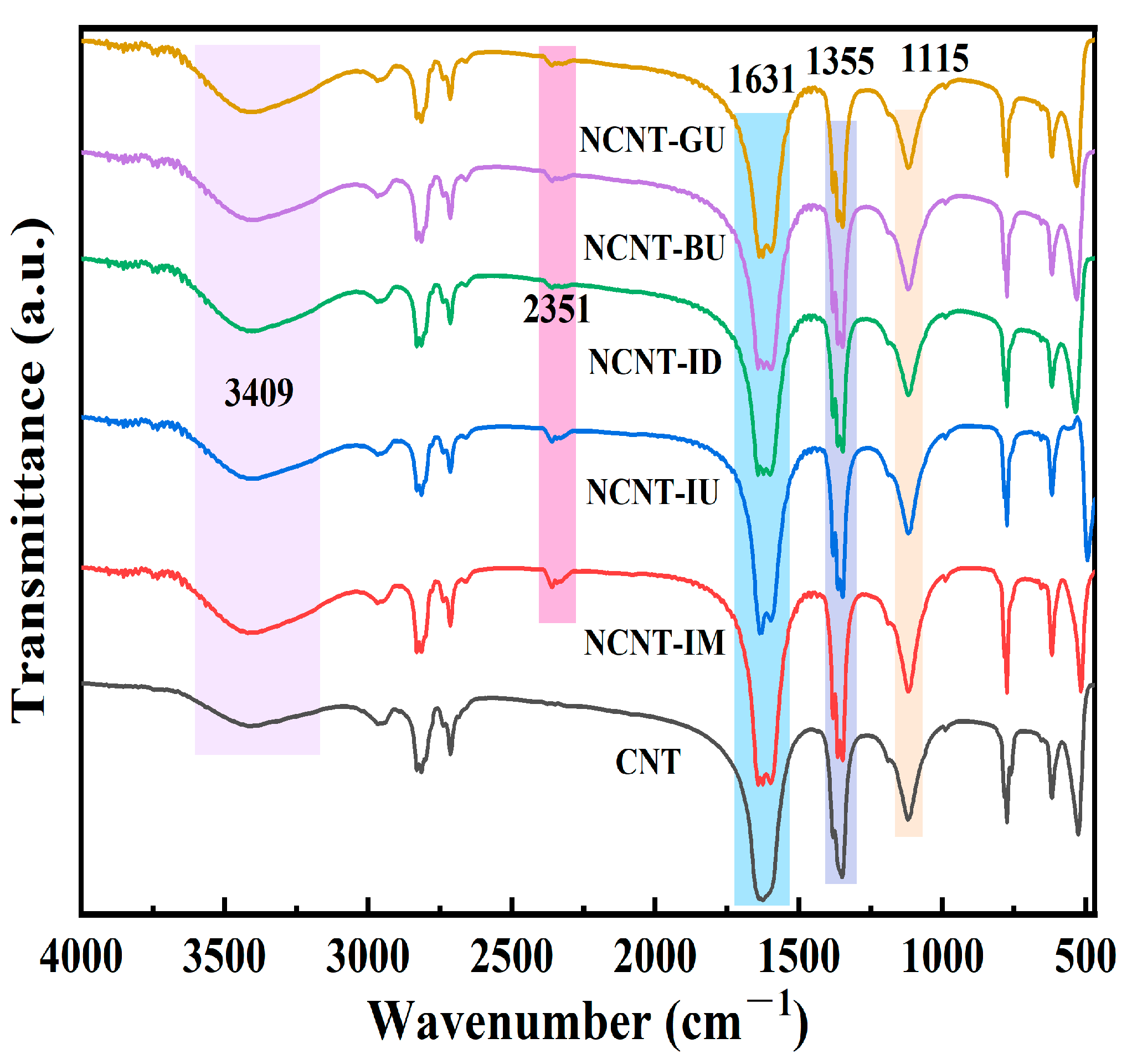
2.1. FTIR Spectra of All Supports

Figure 1 presents the FTIR spectra of pristine carbon nanotubes and nitrogen-doped carbon nanotubes (NCNT) in the 500–4000 cm−1 range. All nitrogen-doped modified carbon nanotubes exhibit a transmission peak near 2351 cm−1, which is attributed to the stretching of C-N bonds [49]. In contrast, pristine carbon nanotubes do not exhibit a peak near 2351 cm−1, confirming that each doping method successfully incorporated nitrogen atoms into the nanotubes. This result is consistent with the elemental analysis (EA) data presented in Table S1. The broad band near 3409 cm−1 corresponds to O-H or N-H stretching vibrations, indicating that numerous surface groups are bound to the MWCNT surface [50]. The peak near 1631 cm−1 is attributed to the conjugated C=C stretching vibration, a typical characteristic of carbon materials [51]. The peak near 1355 cm−1 is attributed to O-H, while the peak near 1115 cm−1 likely corresponds to C-O bond stretching vibrations in carboxyl or alcohol groups.

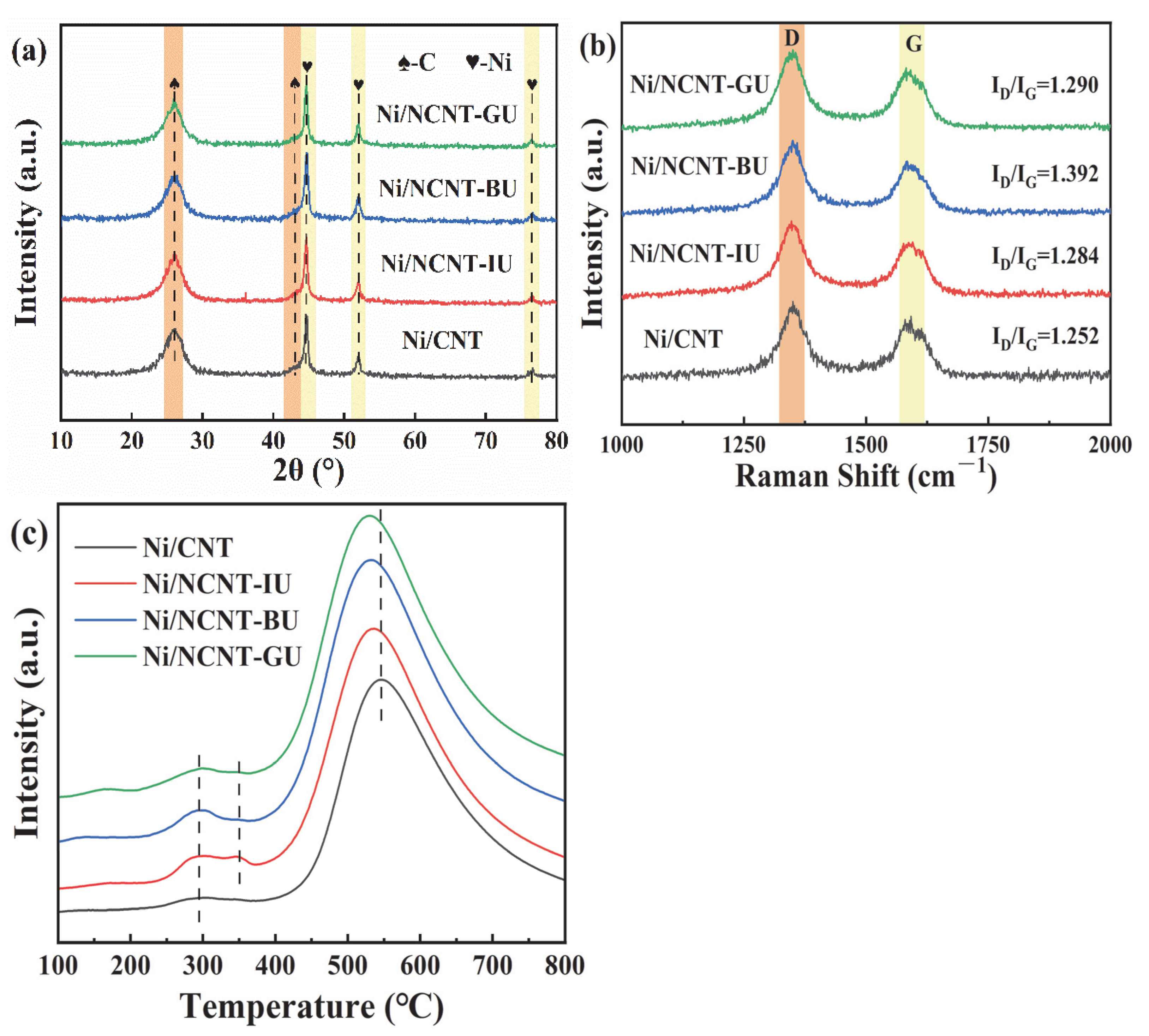
2.2. Effect of Nitrogen Precursors on Catalysts

The structural properties of the supports were analyzed by examining the nitrogen adsorption–desorption isotherms and pore size distribution of each support and catalyst. As shown in Figure 2a, all supports exhibited type IV adsorption isotherms typical of mesoporous materials and type H1 hysteresis loops indicative of large mesoporous carbon materials. The hydrophobicity of the carbon nanotube walls and the stacking of tube bundles led to low adsorption at the initial stage, followed by a sharp increase in adsorption in the high-pressure region (P/P0 > 0.8) [44,52]. As shown in Figure 2c, nitrogen doping made the pore size of carbon nanotubes smaller and more uniform. According to Table 1, the specific surface area of nitrogen-doped carbon nanotubes decreased, likely due to the introduction of nitrogen atoms, which blocked some pores [46]. Compared to pristine CNTs, nitrogen-doped carbon nanotubes prepared with dicyandiamide exhibited the most significant changes in pore characteristics, with specific surface area decreasing from 254.9 m2/g to 126.3 m2/g, pore volume from 2.02 cm3/g to 0.81 cm3/g, and average pore diameter from 22.3 nm to 18.8 nm. EA characterization revealed that although melamine and dicyandiamide could introduce more nitrogen atoms into carbon nanotubes, excessive nitrogen doping blocked many pores. In contrast, doping with urea had a smaller effect on the pore structure of carbon nanotubes, with minimal changes in the specific surface area, pore volume, and average pore diameter of NCNT-IU. As shown in Figure 2b, the adsorption isotherm type remained unchanged after nickel deposition, indicating that CNT and NCNT possess stable mechanical structures. Additionally, as shown in Figure 2d, the nickel particles penetrate the carbon nanotube pores, further reducing the average pore size compared to the support material in Figure 2b. The specific surface area and pore volume of all catalysts are summarized in Table 1. The specific surface area of nitrogen-containing catalysts increased after nickel loading. A primary factor in this is the formation of small openings in the carbon nanotubes due to ultrasonic impregnation and reduction during nickel loading. Additionally, depolymerization of the carbon nanotube bundles occurs, which further increases the specific surface area, as shown in the TEM images [35]. Meanwhile, the total pore volume decreased, likely due to the aggregation of some tube bundles during nickel deposition [53,54].
The XRD analysis of the fresh catalysts, shown in Figure 3a, reveals that all catalysts have similar phase compositions. The peaks at 25.9° and 43.1° in Figure 3a correspond to the (0 0 2) and (1 0 0) crystal planes of graphite, respectively. Nickel in the catalysts exhibited a face-centered cubic structure, with peaks at 44.6°, 51.9°, and 76.5° corresponding to the (1 1 1), (2 0 0), and (2 2 0) facets of nickel, respectively. This is in excellent agreement with Ni (ICDD #04-002-9123). No impurity peaks were detected in the XRD plots, and no NiO peaks were observed. However, peaks corresponding to Ni2+ were clearly deconvoluted in the XPS Ni 2p spectrum. It is possible that the surface NiO did not crystallize into a long-range ordered structure during roasting but instead remained in a disordered amorphous state [55,56]. Additionally, the broader Bragg reflection suggests that the catalyst is a nanocrystalline material. Gonçalves et al. identified a diffraction peak near 43.1° as NiO; however, comparison with the XRD diffraction peaks of pure carbon nanotubes (Figure S1) revealed that this peak corresponds to the (1 0 0) face of graphite [57]. The nickel particle sizes, calculated using Scherrer’s formula, are presented in Table S2. The larger nickel particle sizes in catalysts doped with melamine and dicyandiamide may result from excessive nitrogen doping, which blocks support pores. This blockage caused nickel particles to deposit on the carbon nanotube surface, reducing active metal dispersion, consistent with the BET characterization results. Among these, the Ni/NCNT-IU catalyst exhibited the best metal dispersion, with an average nickel particle size of 11.12 nm. According to the statistical results in Table 1, the active metal tends to deposit within the pores of NCNT-IU, enhancing the metal dispersion, which aligns with the significant reduction in pore volume after metal loading. Additionally, the H2-TPD results for all catalysts are summarized in Table S5. The nitrogen-containing catalysts exhibited an enhanced degree of metal dispersion, with Ni/NCNT-IU achieving the highest dispersion of 17.12%. This further confirms that the nitrogen precursor significantly influences the dispersion of nickel particles in the catalyst.
The H2-TPR characterization results of the catalyst are presented in Figure 3b. Figure 3b shows two H2 consumption peaks in all samples except for Ni/NCNT-IU. The hydrogen consumption peak at approximately 280 °C is likely due to the reduction in nickel oxide deposited on the nanotube walls [35]. The smaller peak observed for Ni/NCNT-IU near 350 °C may result from the interaction between the nickel oxide on the tube wall and NCNT-IU. The reduction temperature is influenced by both the size and location of the NiO nanoparticles, which are affected by surface energy interactions [58]. All nitrogen-doped catalysts exhibited lower hydrogen consumption peak temperatures than undoped catalysts in the high-temperature range (>400 °C), indicating that the highly dispersed nickel oxide interacts strongly with the nitrogen-doped carbon nanotubes [59]. This behavior is attributed to the electron-rich nature of the nitrogen functional groups, which is supported by the XPS characterization results. The hydrogen consumption of each catalyst is listed in Table S2, and nitrogen doping increases the H2 consumption of the Ni/NCNT catalyst. The Ni/NCNT-ID catalyst exhibits the highest hydrogen consumption. This is linked to its poorer dispersion, as indicated by the XRD results, and the larger nickel oxide consuming more hydrogen. The XRD and XPS characterization results show that the Ni/NCNT-IU catalyst has better dispersion [35]. This is due to the electron-rich pyridine nitrogen functional group, which reduces more NiO on the surface, allowing for the greater dispersion of active sites on NCNT-IU, thereby enhancing the catalyst’s activity.
The N 1s XPS spectra of the catalyst are shown in Figure 4. Figure 4a shows that the pristine carbon nanotubes do not contain nitrogen. All three nitrogen precursors successfully doped the carbon nanotubes, consistent with the previous EA and FTIR results. The presence of three nitrogen species in the catalyst was confirmed through the deconvolution and fitting of the N 1s XPS spectra. The binding energy around 398.2 eV corresponds to pyridine nitrogen, the energy around 399.4 eV corresponds to pyrrole nitrogen, and the energy around 401.5 eV corresponds to graphitic nitrogen [60]. As shown in Figure 4a, the Ni/NCNT-IU catalyst prepared with urea exhibits a relatively uniform distribution of the three nitrogen species. The catalysts prepared using melamine and dicyandiamide were functionalized with graphitic nitrogen and contained relatively low levels of pyridinic nitrogen. Table S3 shows the relative contents of the three nitrogen groups in the catalysts, with the Ni/NCNT-IU catalyst having the highest pyridine nitrogen content (N-6, 26.09%). In pyridine nitrogen, the nitrogen atom is bonded to two carbon atoms, forming an electron pair. This accelerates electron transfer, improves the electronic environment of the anchored Ni sites, and increases the number of active sites on the catalyst surface, consistent with the Ni 2p XPS results [36,44].
The XPS spectra of Ni 2p for the catalysts are shown in Figure 4b. Each catalyst in Figure 4b exhibits two distinct peaks corresponding to the Ni 2p3/2 and Ni 2p1/2 characteristics, respectively. Deconvolution of the two main peaks reveals that the peak near 853.2 eV is attributed to isolated nickel particles on the carbon nanotube surface, while the peak near 870.5 eV corresponds to reduced Ni0 [61]. The peaks near 863 eV and 880 eV correspond to the satellite peaks in Ni 2p3/2 and Ni 2p1/2, respectively. As shown in Figure 4b, the binding energy of metallic nickel in the nitrogen-doped catalysts shifts towards higher values compared to that of Ni/CNT, to varying extents. The shift in the peaks to a higher binding energy indicates an enhanced metal–support interaction in the catalyst, consistent with the H2-TPR characterization results [62]. To further analyze the dispersion of nickel particles in the catalyst, we calculated the area ratio of the fitted peaks of the main characteristics, with the specific data presented in Table S3. The Ni/CNT catalyst has the lowest Ni0/Ni2+ ratio (0.61), indicating a weak interaction between nickel and carbon nanotubes on the catalyst surface, which makes the catalyst more prone to oxidation [63]. In contrast, both Ni0/Ni2+ ratios of the nitrogen-doped catalysts were higher than that of Ni/CNT, further demonstrating that nitrogen doping enhances the metal–support interaction and improves the chemical environment on the carbon nanotube surface, thereby increasing the amount of active nickel in the catalysts.
As shown in Figure 5a,c, nickel nanoparticles are predominantly deposited on the outer wall of the CNT tube, with only a small fraction entering the tube. Therefore, the domain-limiting effect on the nickel–metal particle size inside the tube can be excluded. The entanglement between the NCNT-IU tube bundles is improved, facilitating the adsorption of reactive gases and the resolution of products. This also inhibits the inverse water–gas shift reaction, leading to an increase in the H2/CO product ratio. TEM image analysis revealed that the average diameter of Ni particles in Ni/CNT was 14.18 nm, while that in Ni/NCNT-IU was 11.92 nm (Figure 5b,d), consistent with the results obtained using Scherrer’s formula. The pyridine nitrogen functional group strengthens the metal–support interaction in Ni/NCNT-IU, promoting the high dispersion of nickel nanoparticles on the support surface and effectively reducing the particle size. Smaller nickel nanoparticles expose more active sites, consistent with the Ni 2p XPS calculations [64]. Additionally, the strong interaction between nickel and NCNT-IU prevents agglomeration, enhancing the catalyst’s sintering resistance.

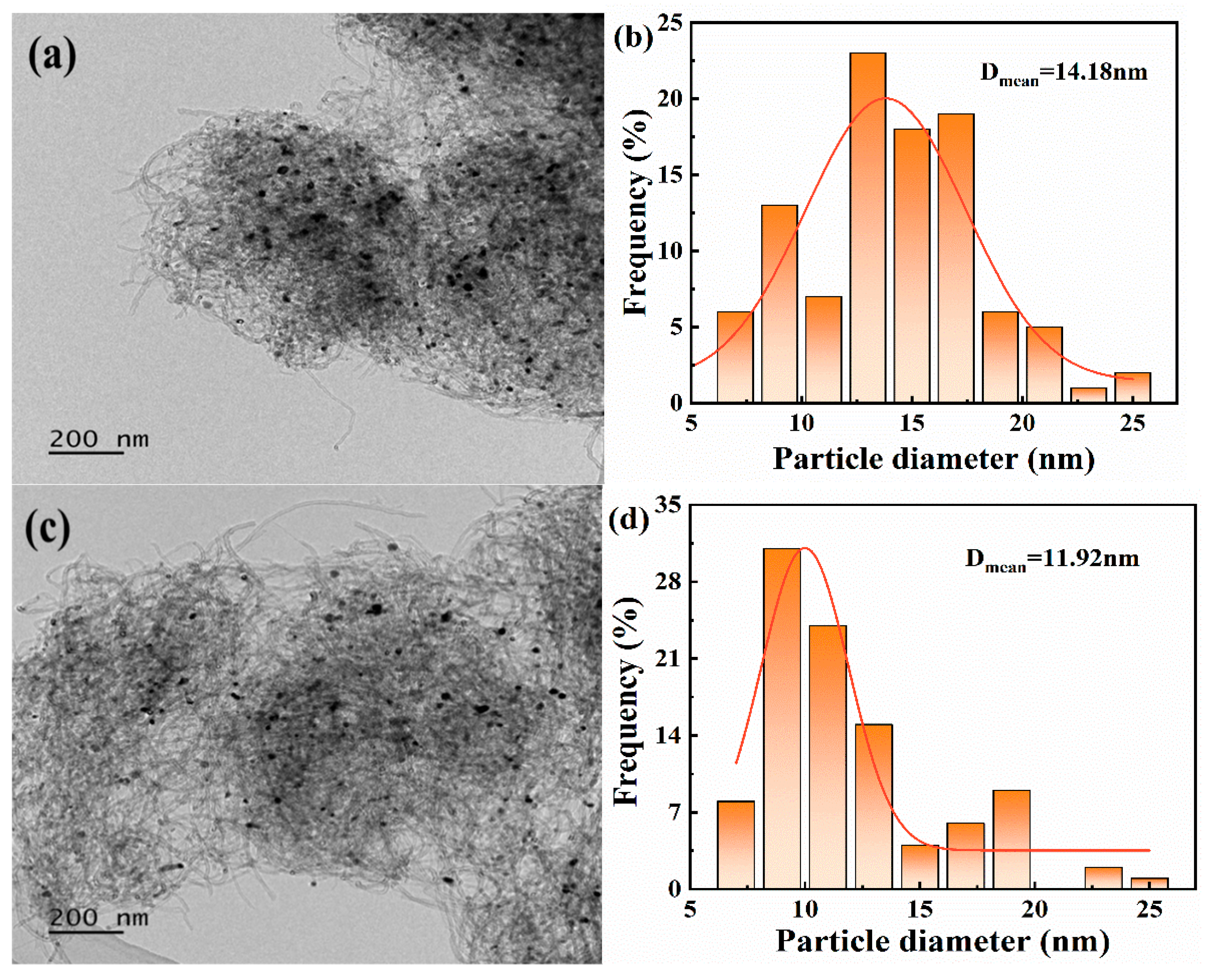
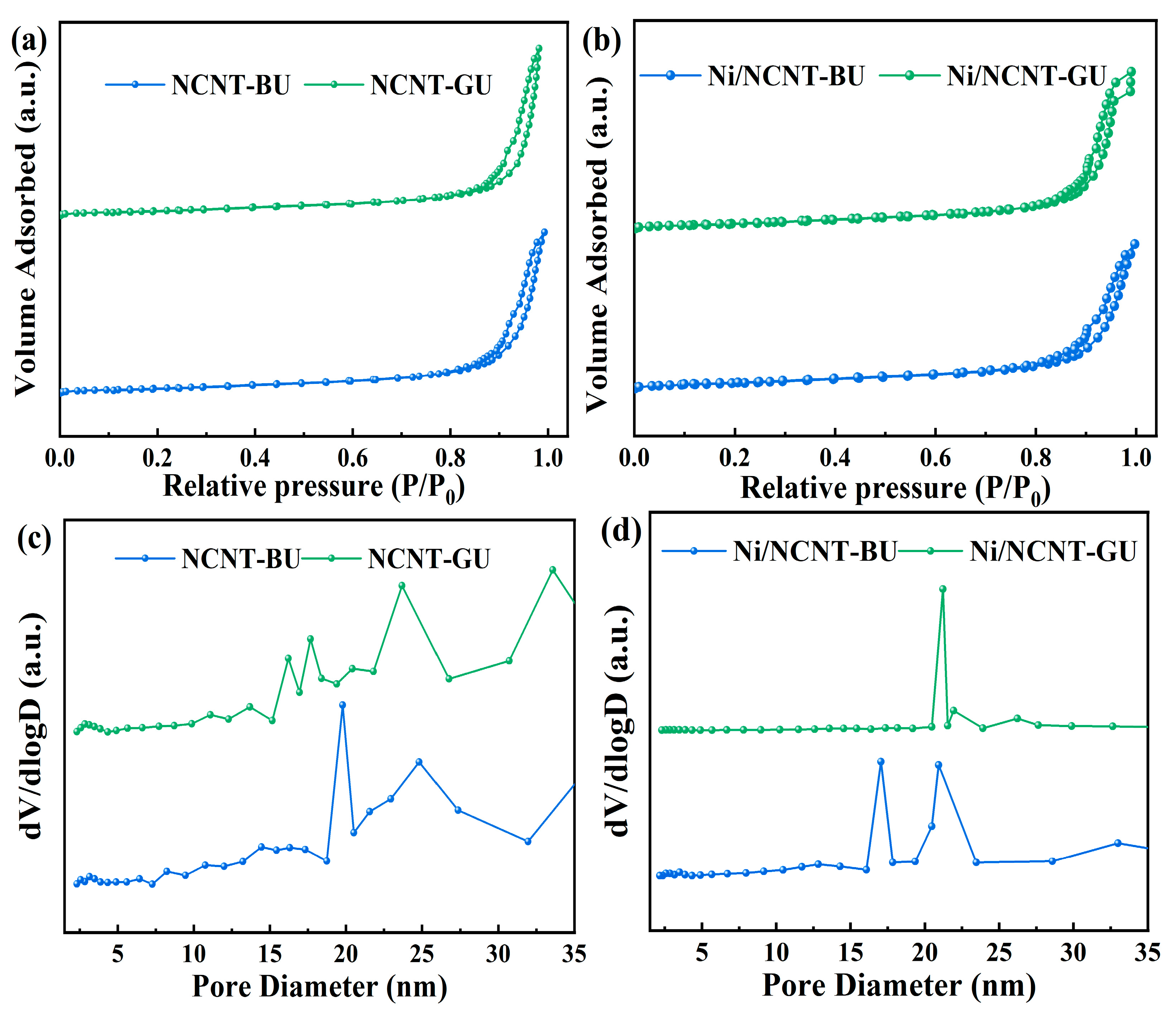
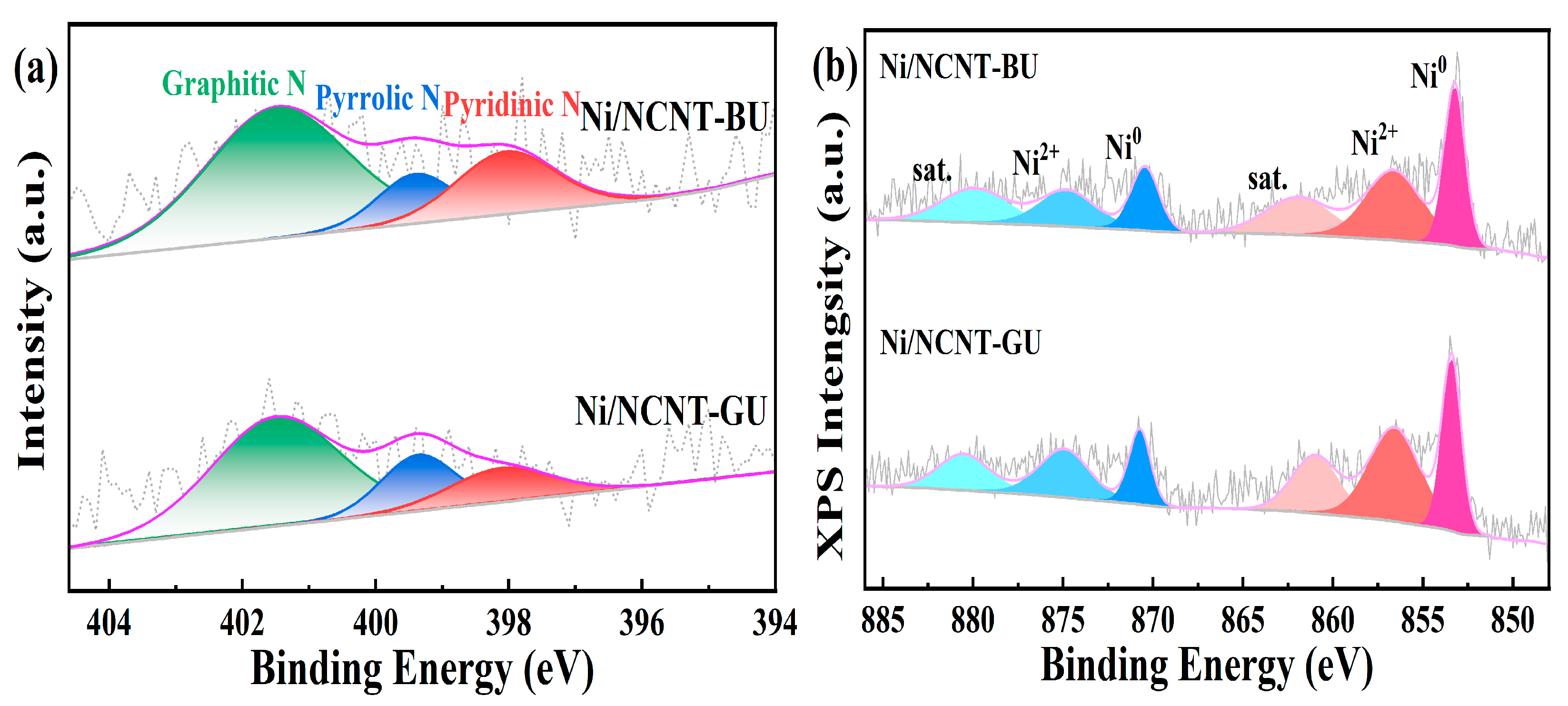
2.3. Effect of Mixing Method on Catalysts

The structural properties of the supports were analyzed by examining the nitrogen adsorption–desorption isotherms and pore size distributions of each support and catalyst. As shown in Figure 6a,c, the isotherm types and pore size distributions remained unchanged, despite the use of different mixing methods. All NCNT supports displayed type IV adsorption isotherms and type H1 hysteresis loops, which are characteristic of mesoporous materials. The NCNT pore characterization data are presented in Table 1 and Table 2. The three different nitrogen precursor mixing methods did not significantly affect the pore parameters, highlighting the advantage of using urea as a nitrogen precursor. Notably, the NCNT-BU support exhibited the smallest specific surface area (239.6 m2/g), pore volume (1.744 cm3/g), and average pore size (20.3 nm). This can be attributed to the high-energy ball-milling, which causes urea to melt and penetrate the carbon nanotubes via strong capillary action. This disrupts the localized network of CNTs and blocks additional pores [65]. As shown in Figure 6b, the deposition of nickel did not alter the adsorption isotherm type. According to the data in Table 1 and Table 2, the specific surface area of the nitrogen-containing catalysts increased, while the total pore volume and average pore size decreased after nickel loading. The structural property changes in the catalysts prepared using different mixing methods followed the same trend.
Figure 7 shows the XRD and Raman characterization results of the fresh catalyst. In Figure 7a, the crystalline planes of graphite at (0 0 2) and (1 0 0), and of nickel at (1 1 1), (2 0 0), and (2 2 0), can be observed. The phase compositions of all catalysts are similar. This indicates that the phase composition of the catalysts is unaffected by the mixing methods. No NiO peaks are observed in Figure 7a, suggesting that NiO on the catalyst surface is not crystallized into a long-range ordered structure, but exists in a disordered amorphous state. Similarly, the broader diffraction peaks suggest that the prepared catalysts are nanocrystalline materials. The nickel metal particle size, calculated using Scherrer’s formula, is presented in Table S2. As shown in Figure 7b, the Raman spectra of all samples exhibit two prominent peaks: the D band at around 1346 cm−1 and the G band at around 1587 cm−1. The D band is typically associated with defects and disordered structures in carbon materials, while the G band arises from the sp2 graphitic C-C stretching vibrations in the carbon structure. The intensity ratio of the D band to the G band (ID/IG) is commonly used to assess the degree of defects in carbon materials [66,67]. Figure 7b indicates that the defect levels in the nitrogen-containing catalysts are higher than those in Ni/CNT. The presence of defects improves metal particle dispersion, modulates the catalyst’s electronic environment, and enhances metal–support interactions [45]. The average size of nickel particles in Ni/NCNT-BU, calculated using Scherrer’s formula, is 12.9 nm, which correlates with the high defect density (ID/IG) = 1.392). Among the nitrogen precursor mixing methods, mechanical ball-milling with prolonged frictional shear breaks up carbon nanotubes, resulting in a higher defect density. The higher defect density in the other two catalysts may be due to nitrogen atom doping [44].
The H2-TPR characterization results of the catalyst are presented in Figure 7c. As shown in Figure 7c, all nitrogen-doped catalysts exhibit three peaks. The urea-modified catalysts display a small peak at around 350 °C, in contrast to the catalysts doped with melamine and dicyandiamide, suggesting enhanced interactions between urea-doped carbon nanotubes (NCNT-XU) and nickel nanoparticles on the tube walls. The hydrogen consumption peak temperatures of Ni/NCNT-XU are lower than those of the undoped catalysts at high temperatures (>400 °C), indicating that the highly dispersed nickel oxide interacts more strongly with the NCNT-XU tubes, consistent with the Ni 2p XPS results. The hydrogen consumption of each catalyst is summarized in Table S2. After nitrogen doping, the hydrogen consumption of Ni/NCNT increased in all cases. Notably, Ni/NCNT-BU exhibits the highest rate of hydrogen consumption. The XRD and XPS characterization results indicate that the active metal particle size in the catalyst is small, and the surface contains a high Ni0/Ni2+ ratio. This may be attributed to unpaired electrons in the defects, which enhance the electronic environment on the support surface and facilitate the reduction in surface NiO [45].
The XPS spectra for the N 1s and Ni 2p regions of the catalysts are shown in Figure 4a and Figure 8a. Figure 4a and Figure 8a demonstrate that all three mixing methods can effectively modify carbon nanotubes through nitrogen doping, which aligns with the previous EA and FTIR results. Deconvolution and fitting of the N 1s XPS spectra revealed three distinct peaks—pyridine nitrogen (398.1 eV), pyrrole nitrogen (399.4 eV)—and graphite nitrogen (401.5 eV), in this order. The relative contents of the three nitrogen groups in the catalysts are summarized in Table S3. The pyridine nitrogen content for the three mixing methods was as follows Ni/NCNT-IU (26.09%), Ni/NCNT-BU (21.02%), and Ni/NCNT-GU (16.06%). This suggests that the mixing method equally influences the relative content of the three nitrogen functional groups. Combined with the N 1s XPS results, the liquid-phase impregnation method ensures the uniform dispersion of urea and CNT at the molecular level, allowing more urea precursors to reach the CNT edges or defects. During the subsequent pyrolysis process, nitrogen atoms underwent reconfiguration via hybridization, resulting in the formation of more pyridine nitrogen functional groups. In contrast, solid-phase mixing was insufficient, leading to a higher substitution of nitrogen atoms in the graphite layer, which resulted in the formation of more graphite nitrogen groups. The XPS spectra of Ni 2p for the catalysts are presented in Figure 4b and Figure 8b. Figure 4b and Figure 8b show that the binding energies of metallic nickel in the nitrogen-doped catalysts shift to higher values compared to Ni/CNT. This suggests a stronger interaction between the nickel nanoparticles and NCNT, consistent with the H2-TPR characterization results. To further investigate the dispersion of nickel particles in the catalyst, the area ratios of the fitted peaks in the main characteristic peaks were calculated, with the specific data provided in Table S3. The highest Ni0/Ni2+ ratio (0.85) was observed in the Ni/NCNT-BU catalyst. Raman spectroscopy analysis, combined with the defective structure and pyridine nitrogen functional groups, shows that these factors synergistically promote the reduction in NiO and increase the number of active sites in the catalyst [44]. Both the defective structure and pyridine nitrogen possess unique electron-rich properties, enhancing the metal–support interaction and exposing more active sites on Ni/NCNT-BU, thereby improving DRM reaction activity.

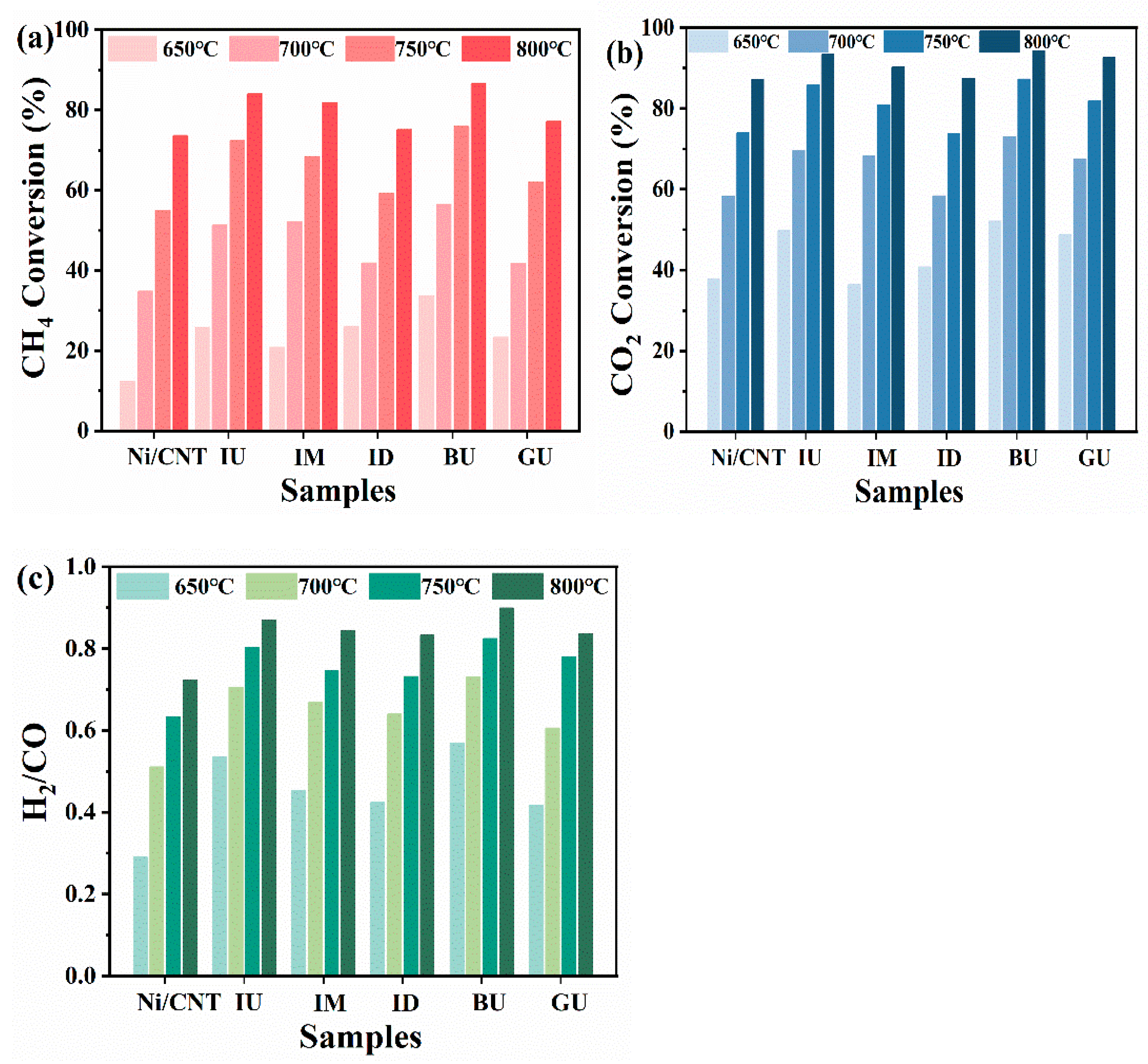
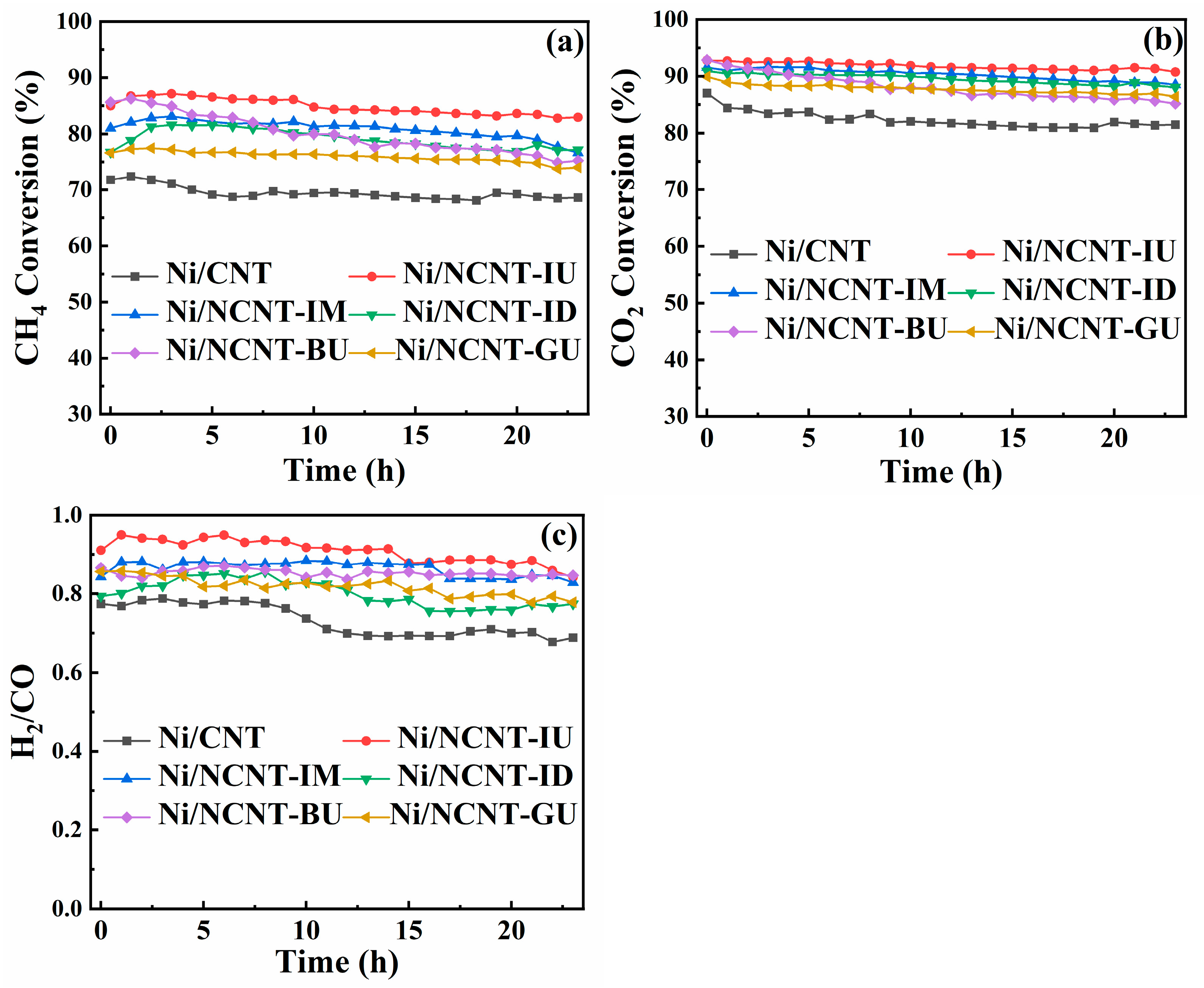
2.4. Catalyzing the Dry Reforming of Methane

The DRM activity test of the catalyst is presented in Figure 9. Figure 9 illustrates that the catalyst activity is significantly influenced by temperature, particularly the methane conversion rate. This is due to the highly endothermic nature of the methane dry reforming reaction. Additionally, CO2 conversion exceeds methane conversion, and the H2/CO ratio is below 1, suggesting the occurrence of a side reaction: the reverse water–gas shift reaction (CO2 + H2 ↔ H2O + CO). Figure 9a,b depict the CH4 and CO2 conversion rates of the catalysts, respectively, with both nitrogen-doped catalysts showing improved DRM activity. This improvement is due to the incorporation of nitrogen-containing functional groups, which enhance electron transfer in the catalysts and strengthen the interaction between active nickel and carbon nanotubes. This leads to the exposure of more active sites on the surface of the nitrogen-doped catalysts. The urea doping method yields the best results, as it introduces nitrogen functional groups into carbon nanotubes without the excessive doping that would block their pores. Additionally, it promotes the dispersion of active metals on the carbon nanotube surface, significantly enhancing catalytic activity. In contrast, catalysts doped with cyanamide-based nitrogen precursors (e.g., melamine and dicyandiamide) blocked numerous pores, causing the active nickel nanoparticle size to increase and leading to reduced catalytic performance. Among the three nitrogen functional groups, the lone pair of electrons on pyridine nitrogen facilitates the reduction in NiO nanoparticles. This increases the Ni0/Ni2+ ratio on the catalyst surface, increasing the number of active sites and enhancing the DRM reaction activity. The mixing method significantly affects the catalytic activity when using the same nitrogen precursor doping. The mechanical ball-milling method significantly increases the catalyst’s defect density. The unpaired electrons in the defects improve the electronic environment of the Ni sites, resulting in the highest initial catalytic activity with the most Ni0 species on the Ni/NCNT-BU surface. In contrast, milling may cause the inhomogeneous mixing of nitrogen precursors and carbon nanotubes. This results in fewer nitrogen atoms reaching the edges of the nanotubes and more replacing nitrogen in the graphite layer, forming more graphitic nitrogen functional groups. In contrast, impregnation—a liquid–solid dispersion process—promotes the mixing of nitrogen precursors and CNTs. Static adsorption enables more urea to reach the edges or defects of CNTs, resulting in the highest pyridine nitrogen content in Ni/NCNT-IU.
The results of all catalyst stability tests are presented in Figure 10. After 24 h of the methane dry reforming reaction, the methane conversion of Ni/NCNT-IU decreased from 85.00% to 82.59%, a change of only 2.05%. Similarly, the carbon dioxide conversion decreased from 92.78% to 90.74%, a 2.04% reduction. In contrast, the methane and carbon dioxide conversions of Ni/NCNT-BU and Ni/NCNT-IM decreased significantly. Specifically, methane conversion decreased by 10.39% and 4.42%, and carbon dioxide conversion by 7.69% and 3.07%, respectively. Furthermore, the H2/CO ratio of Ni/NCNT-IU was closest to 1, which can be attributed to the pyridine nitrogen functional group. This group improved the electronic environment on the support surface, enhanced the metal–support interactions, and facilitated the better dispersion of activated nickel particles, leading to superior catalytic activity and stability. The CO and H2 yields for all catalysts are presented in Figure S3, with Ni/NCNT-IU achieving the highest hydrogen yield in the 24 h methane dry reforming reaction. Additionally, the lower carbon monoxide yield for Ni/NCNT-IU suggests a lower occurrence of side reactions, such as the reverse water–gas shift reaction. The results of nickel-based carbon nanotube-catalyzed DRM studies are presented in Supplementary Information Table S4, where Ni/NCNT-IU exhibits superior catalytic performance. Figure S2 presents the TEM maps and particle size distributions of the spent Ni/CNT and Ni/NCNT-IU catalysts. The carbon nanotube supports in the spent catalysts retained their intact shapes owing to their strong mechanical strength and thermal stability. After the 24 h stability test, the size of the nickel nanoparticles increased in both catalysts. However, the pure carbon nanotube supports exhibited more severe entanglement between tube bundles, leading to the increased aggregation of nickel particles, which are prone to agglomeration and sintering. In contrast, the entanglement of NCNT-IU was improved, and the nickel nanoparticles were well-dispersed, possibly due to the doping of nitrogen functional groups.

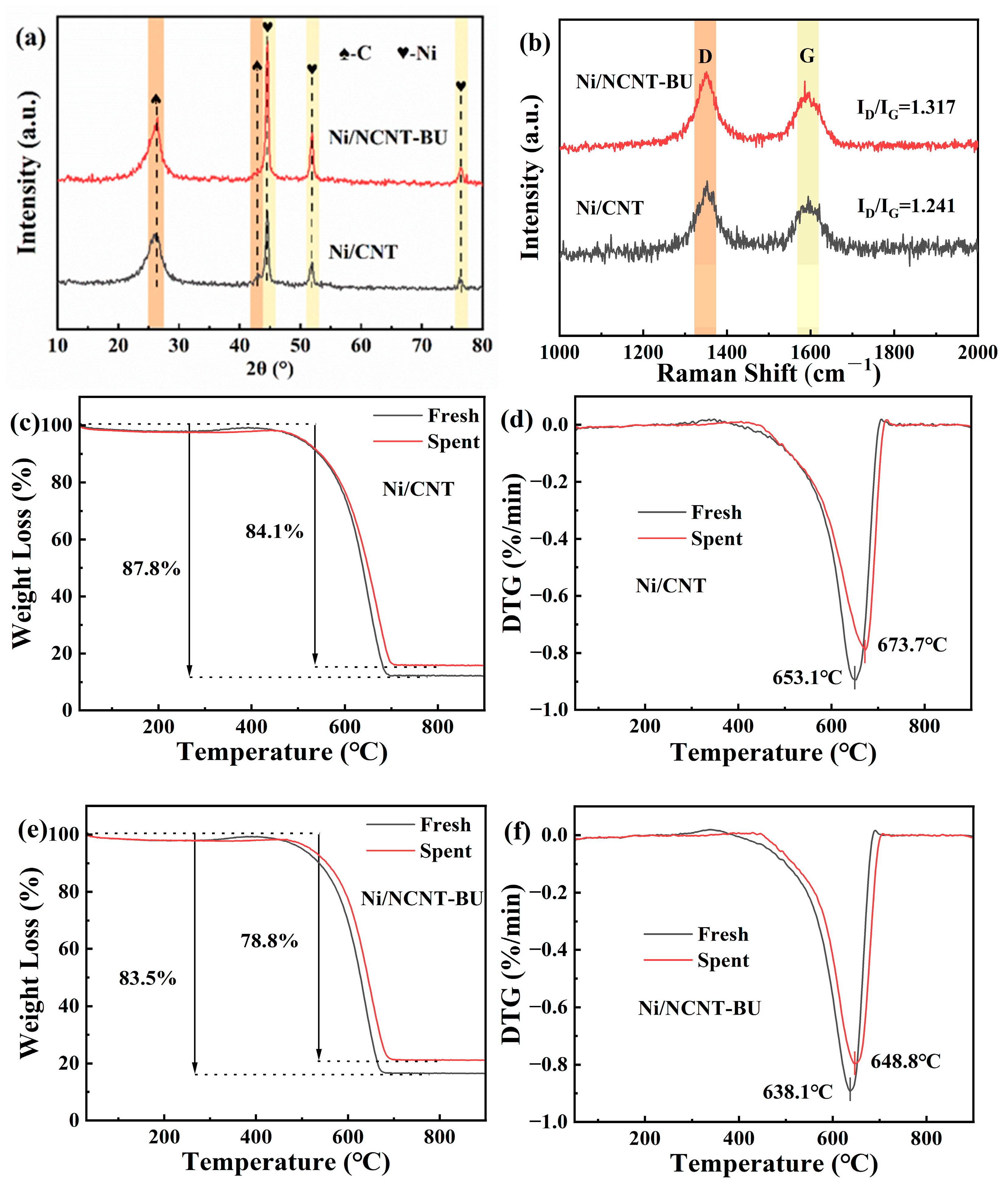
2.5. Probing the Causes of Ni/NCNT-BU Inactivation

Figure 11a presents the XRD characterization results of the spent Ni/CNT and Ni/NCNT-BU. After 24 h of DRM, the nickel diffraction peaks of both catalysts sharpened, indicating that agglomeration occurred in both cases. The nickel diffraction peak of spent Ni/NCNT-BU was significantly sharper than that of spent Ni/CNT. The Ni/NCNT-BU nickel metal particle size increased from 12.90 nm to 15.44 nm, as calculated using Scherrer’s formula. Figure 11b displays the Raman characterization results of the spent Ni/CNT and Ni/NCNT-BU. In the figure, the D band near 1347 cm−1 corresponds to amorphous carbon, while the band near 1598 cm−1 corresponds to graphitized carbon. The ID/IG ratio is commonly used to indicate the degree of graphitization of the spent catalyst [68,69]. The degree of graphitization of both catalysts increased after the 24 h stability test. The ID/IG ratio of Ni/NCNT-BU decreased from 1.392 to 1.317 compared to Ni/CNT, suggesting that more graphitic carbon was deposited in the catalyst. Additionally, TG and DTG tests were performed on both fresh and spent catalysts, with the results being presented in Figure 11c–f. The maximum weight loss for the fresh Ni/CNT catalyst was 87.8% at approximately 653.1 °C, while the maximum weight loss for the fresh Ni/NCNT-BU catalyst was 83.5% at around 638.1 °C. This is consistent with the weight loss temperature of carbon nanotubes [70]. The forward shift in the weight loss temperature of Ni/NCNT-BU is attributed to the mechanical ball-milling, which destabilizes the thermal stability of the carbon nanotubes. The mass loss in the spent catalysts consists of two components: one from the original carbon gasification in the support carbon nanotubes, and the other from carbon deposited during the DRM reaction. The total mass loss for both spent catalysts was lower than that of the fresh catalysts, indicating that both catalysts produced graphitized carbon, which was difficult to gasify during the 24 h stability test. The mass loss of the spent Ni/NCNT-BU catalyst was lower than that of the spent Ni/CNT, suggesting that more graphitized carbon was generated by Ni/NCNT-BU, which corresponds to the high reactivity of the Ni/NCNT-BU catalyst and is consistent with the Raman characterization. In summary, we conclude that the frictional shear during mechanical ball-milling decreases the stability of the carbon nanotube structure. Consequently, the catalyst is more easily gasified during the DRM reaction, which intensifies the migration of nickel nanoparticles on the support surface, leading to the agglomeration and sintering of activated nickel particles. The high methane cracking rate initially caused rapid coking and deposition on the active nickel surface. The growth of metal agglomerates further exacerbated the methane cracking reaction, leading to a rapid decrease in the catalytic activity of Ni/NCNT-BU.

3. Experimental Section

3.1. Materials

Carbon nanotubes (CNT) (Suiheng Graphene Technology, Shenzhen, China, >98%) with a tube diameter 3–15 nm and tube length 15–30 μm, urea (Tianjin Damao Chemical Reagent Factory, Tianjin, China), melamine, and dicyandiamide (Aladdin Biochemical Technology Co., Ltd., Shanghai, China, ≥99%) were used in the experiment. All chemicals used were of analytical grade and did not require further purification or modification during the experiment.

3.2. Synthesis of NCNT-XY and Catalysts

3.2.1. Synthesis of NCNT-XY

X denotes the method used to mix the nitrogen precursor and carbon nanotubes (I stands for impregnation mixing, B stands for mechanical ball-milling, and G stands for normal grinding). A total of 2 g of carbon nanotubes and an equal mass of urea were weighed and dispersed in 50 mL of deionized water and stirred at room temperature for 5 h, before being placed into a 105 °C blast-drying oven overnight. The dried mixture was transferred to a tube furnace and heated to 600 °C for 1 h under a nitrogen atmosphere to obtain NCNT-IU [36]. A total of 2 g of carbon nanotubes and an equal mass of urea were placed in a ball-milling jar and ball-milled in a ball mill at 800 r/min for 4 h [35]. NCNT-BU was obtained using the aforementioned roasting method. A total of 2 g of carbon nanotubes and an equal mass of urea were weighed, placed in a mortar, and manually ground until well mixed [45]. The same roasting method was then applied to obtain NCNT-GU.
Y represents the different nitrogen precursors (U for urea, M for melamine, and D for dicyandiamide). A total of 2 g of carbon nanotubes and an equal mass of nitrogen precursors were weighed and mixed using the impregnation method described above. Different NCNT-IY results were then obtained by following the previously mentioned drying and roasting process.

3.2.2. Synthesis of Catalysts

A total of 1 g of NCNT-XY was weighed and dispersed in deionized water, followed by stirring to form a homogeneous dispersion. Then, 0.495 g of nickel nitrate hexahydrate was dissolved in 4 mL of deionized water (theoretical nickel metal loading of 10 wt.%). The NCNT-IU dispersion was then placed in an ultrasonic bath, and an aqueous solution of nickel nitrate hexahydrate was slowly added. The mixed solution was maintained in the ultrasonic bath for 90 min, followed by drying at 120 °C overnight. After drying, the samples were placed in a tube furnace for roasting. Ni/NCNT-XY was synthesized by heating to 550 °C at a rate of 5 °C/min under a nitrogen flow of 100 mL/min for 3 h. For comparison, the Ni/CNT catalyst was synthesized using the same preparation method, but without the nitrogen doping of the carbon nanotubes.

3.3. Catalytic Characterization

The characterization apparatus, along with the associated experimental procedures and conditions, are detailed in the Supplementary Information.

3.4. Catalytic Test

The performance of the Ni/CNT and Ni/NCNT catalysts in the methane dry reforming reaction was assessed at atmospheric pressure. A total of 0.4 g of catalyst was mixed with 1.2 g of quartz sand and loaded into quartz tubes with a length of 500 mm, an outer diameter of 16 mm, and an inner diameter of 13 mm. Prior to the reaction, the catalyst was reduced in pure hydrogen at 800 °C for 1 h at a flow rate of 50 mL/min. Subsequently, the quartz tube was purged of hydrogen using nitrogen, and methane and carbon dioxide gases were introduced at a 1:1 ratio, with a total flow rate of 120 mL/min (CH4 = CO2 = 60 mL/min), to evaluate the stability and activity of Ni/NCNT at an airspeed of 18,000 mLgcat−1 h−1. Activity tests were conducted within the temperature range of 650–800 °C (650 °C, 700 °C, 750 °C, and 800 °C). Each temperature was maintained for 1 h before testing. In contrast, the stability tests were conducted continuously for up to 24 h during the dry reforming reaction of methane. The reaction off-gas was analyzed using a gas chromatograph (GC950II, Fuli Company) equipped with a thermal conductivity detector (TCD). The CH4, CO2, and CO signals were detected using a hydrogen TCD, while the hydrogen signal was detected with an argon TCD. The calculation formula is presented as follows:
CH 4   conversion = F in , CH 4 F out , CH 4 F in , CH 4 × 100 %
CO 2   conversion = F in , CO 2 F out , CO 2 F in , CO 2 × 100 %
H 2 / CO = F out , H 2 F out , CO
The variables Fin and Fout, as mentioned in the above equation, represent the inlet and outlet gas flow rates, respectively.

4. Conclusions

This paper reports on a Ni/NCNT catalytic system, where nitrogen-doped carbon nanotubes (CNTs) serve as the support for the DRM reaction. Under identical preparation conditions, the nickel-based catalyst using NCNT as the support outperformed the one using CNT as the support in the DRM reaction. The type of nitrogen precursor significantly impacts the physicochemical properties of the catalysts. Cyanamides (melamine, dicyandiamide) can introduce a substantial number of nitrogen-containing groups into carbon nanotubes, but excessive doping can clog the support pores, hindering the dispersion of nickel nanoparticles. Furthermore, the mixing method also significantly affects the physicochemical properties of the catalyst. While mechanical ball-milling enhances the defect density on the catalyst surface, prolonged frictional shearing reduces the stability of the carbon nanotube structure. During the DRM reaction, the supports are prone to gasification, which destroys the structure and reduces catalyst stability. Ni/NCNT-IU exhibited superior catalytic activity and stability compared to all other catalysts. This can be attributed to the high relative content of pyridinic nitrogen functional groups in Ni/NCNT-IU, which enhances the electronic properties of the support surface and strengthens the metal–support interactions, thereby improving metal dispersion. Additionally, pyridinic nitrogen facilitates the reduction of Ni2+ to catalytically active Ni0, exposing more active sites in the catalyst. The liquid-phase impregnation method ensures the uniform molecular-level dispersion of the nitrogen precursor in CNTs, promoting the urea precursors’ penetration into CNT edges or defects and leading to the formation of more pyridinic nitrogen functional groups. After 24 h of reaction at 800 °C, the methane conversion of Ni/NCNT-IU decreased from 85.0% to 82.9%. The breakthrough results of this study show a significant improvement compared to the existing literature data and serve as a valuable reference for advancing the industrialization of methane dry reforming technology.

Supplementary Materials

The following supporting information can be downloaded at: https://www.mdpi.com/article/10.3390/catal15060559/s1, Figure S1: XRD patterns of the pristine CNT. Figure S2: TEM micrographs of (a) spent Ni/CNT and (c) spent Ni/NCNT-IU, and particle size distribution histograms of (b) spent Ni/CNT and (d) spent Ni/NCNT-IU. Figure S3: DRM yield of different catalysts: (a) CO yield; (b) H2 yield. Table S1: Elemental composition of pristine CNT and the synthesized NCNT. Table S2: Fresh catalyst metal particle size, hydrogen consumption, and XPS Ni 2p Ni0/Ni2+. Table S3: Proportions of various nitrogen species on Ni/NCNT catalysts. Table S4: Summary of Ni/CNT catalyst in DRM. Table S5. Results of H2-TPD measurements in all catalysts [31,32,71,72].

Author Contributions

Conceptualization, Z.T. and G.Z.; methodology, Z.T. and D.S.; software, Z.T.; validation, Z.T.; formal analysis, Y.L. and X.Z.; investigation, Z.T.; resources, G.Z.; writing—original draft, Z.T.; writing—review and editing, G.Z.; visualization, Z.T.; project administration, G.Z.; funding acquisition, G.Z. All authors have read and agreed to the published version of the manuscript.

Funding

This work is supported by the Applied Basic Research Project of Shanxi Province (No. 202303021211032) and National Natural Science Foundation of China (No. 22478270).

Data Availability Statement

The data presented in this study are available on request from the corresponding author.

Conflicts of Interest

The authors declare no conflicts of interest.

References

  1. Shi, Y.; Su, W.; Xing, Y.; Cui, Y.; Liu, X.; Guo, W.; Che, Z. Research progress and future prospects of chemical utilization of CO2. Chem. Eng. J. 2025, 510, 161579. [Google Scholar] [CrossRef]
  2. Montejano-Nares, E.; Martínez-Navarro, B.; López, E.C.; Asedegbega-Nieto, E.; Valiente, Á.M.; Conesa Alonso, J.M.; Rodríguez Ramos, I.; Guerrero Ruíz, A.R.; Ivars-Barceló, F. Avoiding dry reforming control in direct CH4 and CO2 conversion operating at low-temperature below ambient pressure over AgPd4-Fe3-δO4 nanocomposite. Chem. Eng. J. 2023, 474, 145373. [Google Scholar] [CrossRef]
  3. Meng, S.; Lambert, T.H.; Milner, P.J. Harnessing oxidized amines as robust sorbents for carbon capture. J. Am. Chem. Soc. 2025, 147, 6786–6794. [Google Scholar] [CrossRef] [PubMed]
  4. Zhou, L.; Martirez, J.M.P.; Finzel, J.; Zhang, C.; Swearer, D.F.; Tian, S.; Robatjazi, H.; Lou, M.; Dong, L.; Henderson, L.; et al. Light-driven methane dry reforming with single atomic site antenna-reactor plasmonic photocatalysts. Nat. Energy 2020, 5, 61–70. [Google Scholar] [CrossRef]
  5. Lv, H.; Dong, X.; Li, R.; Zeng, C.; Zhang, X.; Song, Y.; Liu, H.; Shao, J.; Ta, N.; Zhao, Q.; et al. Super-dry reforming of methane using a tandem electro-thermocatalytic system. Nat. Chem. 2025, 17, 695–702. [Google Scholar] [CrossRef]
  6. Li, Y.; Yao, L.; Li, J.; Yu, T.; Qiu, L.; Nasir, M.S.; Wang, T.; Rahman, M.A.; Anand, N.; Sadaf, S.M.; et al. GaN nanowire-supported NiOx for low-temperature and durable dry reforming of methane toward syngas. Appl. Catal. B Environ. 2025, 366, 125051. [Google Scholar] [CrossRef]
  7. Su, J.; Liu, C.; Zhou, H.; Zhang, L.; Jiao, W.; Liu, S.; Wang, Y.; Xie, Z. Syngas chemistry: Rational design of tandem reaction pathway for directional hydrocarbon synthesis. Chem 2025, 102552. [Google Scholar] [CrossRef]
  8. Dwarica, N.S.; Rice, P.S.; Groh, J.T.; Gibson, N.J.; Menges, F.S.; Mercado, B.Q.; Raugei, S.; Mayer, J.M. Hydrogen adsorption, reactivity, and catalysis on colloidal iron carbide nanoparticles. ACS Catal. 2025, 15, 6115–6129. [Google Scholar] [CrossRef]
  9. Ahasan, M.R.; Hossain, M.M.; Barlow, Z.; Ding, X.; Wang, R. Low-temperature plasma-assisted catalytic dry reforming of methane over CeO2 nanorod-supported NiO catalysts in a dielectric barrier discharge reactor. ACS Appl. Mater. Interfaces 2025, 15, 44984–44995. [Google Scholar] [CrossRef]
  10. Diao, J.; Zhang, T.; Xu, Z.; Guo, G. The atomic-level adjacent NiFe bimetallic catalyst significantly improves the activity and stability for plasma-involved dry reforming reaction of CH4 and CO2. Chem. Eng. J. 2023, 467, 143271. [Google Scholar] [CrossRef]
  11. Tu, Z.; Mu, C.; Yao, Y.; Wu, L.; Zou, Y.; Tong, Z.; Huang, K. Recent advances in unconventional heating and external field-assisted enhancement for dry reforming of methane. Chem. Eng. J. 2024, 481, 148899. [Google Scholar] [CrossRef]
  12. Al-Fatesh, A.S.; Arafat, Y.; Kasim, S.O.; Ibrahim, A.A.; Abasaeed, A.E.; Fakeeha, A.E. In situ auto-gasification of coke deposits over a novel Ni-Ce/W-Zr catalyst by sequential generation of oxygen vacancies for remarkably stable syngas production via CO2-reforming of methane. Appl. Catal. B Environ. 2021, 280, 119445. [Google Scholar] [CrossRef]
  13. Zhang, Z.; Zhang, Y.; Liu, L. Role and mechanism of calcium-based catalysts for methane dry reforming: A review. Fuel 2024, 355, 129329. [Google Scholar] [CrossRef]
  14. Romay, M.; Serrano, D.P.; Escola, J.M.; Pizarro, P. Unravelling the effectiveness of the small partial substitution of Fe by Ni in La0.9Sr0.1Fe1-xNixO3 perovskites to improve their performance in dry reforming of methane. Chem. Eng. J. 2024, 496, 154039. [Google Scholar] [CrossRef]
  15. Feng, X.; Du, Z.; Sarnello, E.; Deng, W.; Petru, C.R.; Fang, L.; Li, T.; Li, Y. Syngas production at a near-unity H2/CO ratio from photo-thermo-chemical dry reforming of methane on a Pt decorated Al2O3–CeO2 catalyst. J. Mater. Chem. A 2022, 10, 7896–7910. [Google Scholar] [CrossRef]
  16. Gangarajula, Y.; Hong, F.; Li, Q.; Jiang, X.; Liu, W.; Akri, M.; Su, Y.; Zhang, Y.; Li, L.; Qiao, B. Operando induced strong metal-support interaction of Rh/CeO2 catalyst in dry reforming of methane. App. Catal. B Environ. 2024, 343, 123503. [Google Scholar] [CrossRef]
  17. Yu, H.; Wang, Y.; Tao, X.; Yu, F.; Zhao, T.; Li, M.; Wang, H. Interfacial metal–support interaction and catalytic performance of perovskite LaCrO3-supported Ru catalyst. ACS Appl. Mater. Interfaces 2024, 16, 17483–17492. [Google Scholar] [CrossRef]
  18. Liang, D.; Wang, Y.; Wang, Y.; Chen, M.; Xie, X.; Li, C.; Wang, J.; Yuan, L. Dry reforming of methane for syngas production over noble metals modified M-Ni@S-1 catalysts (M = Pt, Pd, Ru, Au). Int. J. Hydrogen Energy 2024, 45, 1002–1015. [Google Scholar] [CrossRef]
  19. Cheng, F.; Duan, X.; Xie, K. Dry reforming of CH4/CO2 by stable Ni nanocrystals on porous single-crystalline MgO monoliths at reduced temperature. Angew. Chem. Int. Ed. 2021, 60, 18792–18799. [Google Scholar] [CrossRef]
  20. Pirshahid, M.R.B.; Alavi, S.M.; Rezaei, M.; Akbari, E.; Varbar, M.; Khosravi, K. Novel highly efficient Ni-based mesoporous alumina-silica supported catalysts for methane dry reforming: Influence of nickel loading. J. Energy Inst. 2023, 110, 123503. [Google Scholar] [CrossRef]
  21. Lyu, L.; Zhang, J.; Ma, Q.; Makpal, S.; Gao, X.; Fan, H.; Zhang, J.; Sun, J.; Zhao, T. Fe doped bimodal macro/mesoporous nickel-based catalysts for CO2-CH4 reforming. Ind. Eng. Chem. Res. 2022, 61, 10347–10356. [Google Scholar] [CrossRef]
  22. Shi, Y.; Tian, X.; Deng, Z.; Shi, W.; Fan, W.; Wang, F. Review and outlook of confined Ni catalysts for the dry reforming of methane reaction. Energy Fuels 2024, 38, 1633–1656. [Google Scholar] [CrossRef]
  23. Gai, X.; Yang, D.; Tang, R.; Luo, M.; Lu, P.; Xing, C. Preparation of Ni-Co/SiO2 catalyst by ammonia reflux impregnation and its CH4-CO2 reforming reaction performance. Fuel 2022, 316, 123337. [Google Scholar] [CrossRef]
  24. Gong, B.; Su, T.; Xie, X.; Ji, H.; Qin, Z. Promotional effects of Mg-substituted Ni/MgxHAP catalysts on carbon resistance during dry reforming of methane. Ind. Eng. Chem. Res. 2023, 62, 12935–12948. [Google Scholar] [CrossRef]
  25. Pinto, D.; Hu, L.; Urakawa, A. Enabling complete conversion of CH4 and CO2 in dynamic coke-mediated dry reforming (DC-DRM) on Ni catalysts. Chem. Eng. J. 2023, 474, 145641. [Google Scholar] [CrossRef]
  26. Kaviani, M.; Rezaei, M.; Alavi, S.M.; Akbari, E. Biogas dry reforming over nickel-silica sandwiched core-shell catalysts with various shell thicknesses. Fuel 2024, 355, 129533. [Google Scholar] [CrossRef]
  27. Qin, Z. Nanostructure design of catalysts: Latest advances and prospects. Nanomaterials 2023, 13, 1980. [Google Scholar] [CrossRef]
  28. Li, L.; Zheng, J.; Liu, Y.; Wang, W.; Huang, Q.; Chu, W. Impacts of SiC support and nickel precursor of NiLa/support catalysts for CO2 selective hydrogenation to synthetic natural gas (SNG). ChemistrySelect 2017, 2, 3750–3757. [Google Scholar] [CrossRef]
  29. Han, K.; Shi, H.; He, G.; Liao, F.; Wang, J.; An, C. Application of Pickering emulsion with multilayer dispersion-enhancement synergy of carbon nanotubes in composite energetic materials. Chem. Eng. J. 2025, 505, 159799. [Google Scholar] [CrossRef]
  30. Hayashi, K.; Nakano, T.; Inoue, Y. Enhancing thermal conduction properties of vertically aligned CNT forests by reducing interfacial thermal resistance using an aluminum interlayer. Carbon 2025, 238, 120256. [Google Scholar] [CrossRef]
  31. Łamacz, A.; Jagódka, P.; Stawowy, M.; Matus, K. Dry reforming of methane over CNT-supported CeZrO2 Ni and Ni-CeZrO2 catalysts. Catalysts 2020, 10, 741. [Google Scholar] [CrossRef]
  32. Ma, Q.; Wang, D.; Wu, M.; Zhao, T.; Yoneyama, Y.; Tsubaki, N. Effect of catalytic site position: Nickel nanocatalyst selectively loaded inside or outside carbon nanotubes for methane dry reforming. Fuel 2013, 108, 430–438. [Google Scholar] [CrossRef]
  33. Wang, W.; Duong-Viet, C.; Ba, H.; Baaziz, W.; Tuci, G.; Caporali, S.; Nguyen-Dinh, L.; Ersen, O.; Gianbastiani, G.; Pham-Huu, C. Nickel nanoparticles decorated nitrogen-doped carbon nanotubes (Ni/N-CNT); A robust catalyst for the efficient and selective CO2 methanation. ACS Appl. Energy Mater. 2019, 2, 1111–1120. [Google Scholar] [CrossRef]
  34. Gödde, J.; Merko, M.; Xia, W.; Muhler, M. Nickel nanoparticles supported on nitrogen-doped carbon nanotubes are a highly active, selective and stable CO2 methanation catalyst. J. Energy Chem. 2021, 54, 323–331. [Google Scholar] [CrossRef]
  35. Gonçalves, L.P.L.; Meledina, M.; Meledin, A.; Petrovykh, D.Y.; Sousa, J.P.S.; Soares, O.S.G.P.; Kolen’ko, Y.V.; Pereira, M.F.R. Understanding the importance of N-doping for CNT-supported Ni catalysts for CO2 methanation. Carbon 2022, 195, 35–43. [Google Scholar] [CrossRef]
  36. Zhang, G.; Sun, Y.; Xu, Y.; Zhang, R. Catalytic performance of N-doped activated carbon supported cobalt catalyst for carbon dioxide reforming of methane to synthesis gas. J. Taiwan Inst. Chem. Eng. 2018, 93, 234–244. [Google Scholar] [CrossRef]
  37. Guo, Y.; Dong, A.; Huang, Q.; Li, Q.; Hu, Y.; Qian, J.; Huang, S. Hierarchical N-doped CNTs grafted onto MOF-derived porous carbon nanomaterials for efficient oxygen reduction. J. Colloid Interface Sci. 2022, 606, 1833–1841. [Google Scholar] [CrossRef]
  38. Yao, Y.; Zhang, J.; Chen, H.; Yu, M.; Gao, M.; Hu, Y.; Wang, S. Ni0 encapsulated in N-doped carbon nanotubes for catalytic reduction of highly toxic hexavalent chromium. Appl. Surf. Sci. 2018, 440, 421–431. [Google Scholar] [CrossRef]
  39. Dong, F.; Liang, X.; Zhang, Z.; Yin, H.; Wang, D.; Li, J.; Li, Y. Atomic Pt Sites Anchored in the Interface between Grains on Vacancy-Enriched CeO2 Nanosheets: One-Step Precursor Combustion Synthesis. Adv. Mater. 2024, 36, 109667. [Google Scholar] [CrossRef]
  40. Chen, L.; Ng, K.H.; Hsu, L. Self-regenerative Ni/SiO2 for dry reforming of methane (DRM): 1000 h-longevity assessment and operando insights to coke removal under N2 atmosphere. Chem. Eng. J. 2024, 499, 155907. [Google Scholar] [CrossRef]
  41. Benedetti, V.; Ail, S.S.; Patuzzi, F.; Baratieri, M. Valorization of char from biomass gasification as catalyst support in dry reforming of methane. Front. Chem. 2019, 7, 119. [Google Scholar] [CrossRef] [PubMed]
  42. Zhang, F.; Liu, X.; Yang, C.; Chen, G.; Meng, Y.; Zhou, H.; Zhang, S. Insights into robust carbon nanotubes in tribology: From nano to macro. Mater. Today 2024, 74, 203–234. [Google Scholar] [CrossRef]
  43. Qiao, M.; Meysami, S.S.; Ferrero, G.A.; Xie, F.; Meng, H.; Grobert, N.; Titirici, M. Low-cost chitosan-derived N-doped carbons boost electrocatalytic activity of multiwall carbon nanotubes. Adv. Funct. Mater. 2018, 28, 1707284. [Google Scholar] [CrossRef]
  44. Jiang, Z.; Shi, Y.; Bai, Y.; Song, X.; Wang, J.; Lv, P.; Wu, S.; Su, W. Pyridinic N and carbon defects synergistically promote methane dry reforming to syngas catalyzed by Co/N-CNTs. Fuel 2023, 337, 127136. [Google Scholar] [CrossRef]
  45. Zhang, X.; Zhang, G.; Liu, J.; Li, G.; Zhao, Y.; Wang, Y.; Lv, Y. Effects of defective structure originating from N incorporation-evaporation of Co-based biomass carbon catalysts on methane dry reforming. Fuel 2024, 357, 129752. [Google Scholar] [CrossRef]
  46. Rocha, R.P.; Soares, O.S.G.P.; Gonçalves, A.G.; Órfão, J.J.M.; Pereira, M.F.R.; Figueiredo, J.L. Different methodologies for synthesis of nitrogen doped carbon nanotubes and their use in catalytic wet air oxidation. Appl. Catal. A Gen. 2017, 548, 62–70. [Google Scholar] [CrossRef]
  47. Xiao, M.; Zhou, Q.; Zhang, Y.; Kou, X.; Niu, D.; Ma, L.; Xu, J. Fabrication of carbon nanotubes with rich Pyridinic nitrogen in H2/Ar atmosphere for efficient electroreduction of CO2 to CO. Diam. Relat. Mater. 2023, 132, 109667. [Google Scholar] [CrossRef]
  48. Soares, O.S.G.P.; Rocha, R.P.; Órfão, J.J.M.; Pereira, M.F.R.; Figueiredo, J.L. Mechanothermal approach for N-, S-, P-, and B-doping of carbon nanotubes: Methodology and catalytic performance in wet air oxidation. Chimia 2019, 5, 30. [Google Scholar] [CrossRef]
  49. Li, Y.; Zhang, T.; Wang, Y.; Wang, B. Transformation of waste cornstalk into versatile porous carbon adsorbent for selective CO2 capture and efficient methanol adsorption. J. Environ. Chem. Eng. 2021, 9, 106149. [Google Scholar] [CrossRef]
  50. Wu, C.; Liu, J.; Wu, W.; Wang, Y.; Zhao, Y.; Li, G.; Zhang, Y.; Zhang, G. Mild modification of sponge-like carbon: Ammonia post-treatment for enhanced CO2 adsorption and suitability for supercapacitors. Sep. Purif. Technol. 2025, 353, 128525. [Google Scholar] [CrossRef]
  51. Zhang, R.; Liu, D.; Wu, D.; Liu, Y.; Gui, J.; Zhong, C.; Chen, S.; Wang, J. Low temperature synthesis of nitrogen-rich biomass for high-performance removal of phosphate. J. Environ. Chem. Eng. 2022, 10, 107000. [Google Scholar] [CrossRef]
  52. Zhang, D.; Wei, G.; Wang, Y.; Wang, J.; Ning, P.; Zhang, Q.; Wang, M.; Zhang, T.; Long, K. Carbon dioxide reforming of methane over MgO promoted Ni/CNT catalyst. Korean J. Chem. Eng. 2018, 35, 1979–1987. [Google Scholar] [CrossRef]
  53. Kim, D.; Kim, J.H.; Li, M.; Noda, S.; Kim, J.; Kim, K.S.; Yang, C. Controllable pore structures of pure and sub-millimeter-long carbon nanotubes. Appl. Surf. Sci. 2021, 566, 150751. [Google Scholar] [CrossRef]
  54. Likodimos, V.; Steriotis, T.A.; Papageorgiou, S.K.; Romanos, G.E.; Marques, R.R.N.; Rocha, R.P.; Faria, J.L.; Pereira, M.F.R.; Figueiredo, J.L.; Silva, A.M.T.; et al. Controlled surface functionalization of multiwall carbon nanotubes by HNO3 hydrothermal oxidation. Carbon 2014, 69, 311–326. [Google Scholar] [CrossRef]
  55. Swetha, A.C.; Ghosh, C.; Dasgupta, A.; Murugadoss, A. Disordered nickel oxide nanostructure-enriched bimetallic AuNi nanoparticles for methanol electrooxidation. ACS Appl. Nano Mater. 2025, 8, 6541–6553. [Google Scholar] [CrossRef]
  56. Wu, Z.; Wang, T.; Zou, J.; Li, Y.; Zhang, C. Amorphous nickel oxides supported on carbon nanosheets as high-performance catalysts for electrochemical synthesis of hydrogen peroxide. ACS Catal. 2022, 12, 5911–5920. [Google Scholar] [CrossRef]
  57. Zhang, M.; Hu, C.; Li, N.; Zhang, Y.; Khodakov, A.; Zhang, Y.; Wang, L.; Li, J.; Hong, J. Low temperature glycerol steam reforming on Ni/CNTs catalysts: The effect of nano-confinement. Int. J. Hydrogen Energy 2024, 91, 1253–1261. [Google Scholar] [CrossRef]
  58. Zhen, W.; Li, B.; Lu, G.; Ma, J. Enhancing catalytic activity and stability for CO2 methanation on Ni@ MOF-5 via control of active species dispersion. Chem. Commun. 2015, 51, 1728–1731. [Google Scholar] [CrossRef]
  59. Shi, L.; Li, Y.; Xue, D.; Tan, P.; Jiang, Y.; Liu, X.; Sun, L. Fabrication of highly dispersed nickel in nanoconfined spaces of as-made SBA-15 for dry reforming of methane with carbon dioxide. Chem. Eng. J. 2020, 390, 124491. [Google Scholar] [CrossRef]
  60. Wang, S.; Wang, J. Degradation of sulfamethoxazole using peroxymonosulfate activated by cobalt embedded into N, O co-doped carbon nanotubes. Sep. Purif. Technol. 2021, 277, 119457. [Google Scholar] [CrossRef]
  61. Daouraa, O.; Fornasieric, G.; Boutrosa, M.; Hassand, N.E.; Beaunierb, P.; Thomasb, C.; Selmane, M.; Miche, A.; Sassoye, C.; Ersen, O.; et al. One-pot prepared mesoporous silica SBA-15-like monoliths with embedded Ni particles as selective and stable catalysts for methane dry reforming. Appl. Catal. B Environ. 2021, 280, 119417. [Google Scholar] [CrossRef]
  62. Zeng, F.; Zhang, J.; Xu, R.; Zhan, R.; Ge, J. Highly dispersed Ni/MgO-mSiO2 catalysts with excellent activity and stability for dry reforming of methane. Nano Res. 2022, 15, 5004–5013. [Google Scholar] [CrossRef]
  63. Li, T.; Liu, J.; Zhang, Y.; Zhang, X.; Wang, Y.; Zhao, Y.; Li, G.; Zhang, G. Utilization of coal gasification fine slag-derived mesoporous silica supports for enhanced dry reforming of methane catalysts. Fuel 2024, 375, 132619. [Google Scholar] [CrossRef]
  64. Amin, R.; Liu, B.; Huang, Z.B.; Zhao, Y.C. Hydrogen and syn gas production via CO2 dry reforming of methane over Mg/La promoted Co–Ni/MSU-S catalyst. Int. J. Hydrogen Energy 2016, 41, 807–819. [Google Scholar] [CrossRef]
  65. Yuan, F.; Huang, Y.; Fan, M.; Chen, C.; Qian, J.; Hao, Q.; Yang, J.; Sun, D. N-doped carbon nanofibrous network derived from bacterial cellulose for the loading of Pt nanoparticles for methanol oxidation reaction. Chem. Eur. J. 2018, 24, 1844–1852. [Google Scholar] [CrossRef]
  66. Madrona, C.; Vila, M.; Oropeza, F.E.; de La Peña O’Shea, V.A.; Vilatela, J.J. Macroscopic yarns of FeCl3-intercalated collapsed carbon nanotubes with high doping and stability. Carbon 2021, 173, 311–321. [Google Scholar] [CrossRef]
  67. Mofokeng, T.P.; Tetana, Z.N.; Ozoemena, K.I. Defective 3D nitrogen-doped carbon nanotube-carbon fiber networks for high-performance supercapacitor: Transformative role of nitrogen-doping from surface-confined to diffusive kinetics. Carbon 2020, 169, 312–326. [Google Scholar] [CrossRef]
  68. Diao, Y.; Zhang, X.; Liu, Y.; Chen, B.; Wu, G.; Shi, C. Plasma-assisted dry reforming of methane over Mo2C-Ni/Al2O3 catalysts: Effects of β-Mo2C promoter. App. Catal. B Environ. 2022, 301, 120779. [Google Scholar] [CrossRef]
  69. Liang, Z.; Zhang, Y.; Zhang, G.; Liu, J.; Cai, Y.; Wang, Y.; Zhao, Y.; Li, G.; Bei, K. Promotion effect of different lanthanide doping on Co/Al2O3 catalyst for dry reforming of methane. Int. J. Hydrogen Energy 2023, 48, 18644–18656. [Google Scholar] [CrossRef]
  70. Wang, Y.; Yao, L.; Wang, Y.; Wang, S.; Zhao, Q.; Mao, D.; Hu, C. Low-temperature catalytic CO2 dry reforming of methane on Ni-Si/ZrO2 catalyst. ACS Catal. 2018, 8, 6495–6506. [Google Scholar] [CrossRef]
  71. Donphai, W.; Faungnawakij, K.; Chareonpanich, M.; Limtrakul, J. Effect of Ni-CNTs/mesocellular silica composite catalysts on carbon dioxide reforming of methane. Appl. Catal. A Gen. 2014, 475, 16–26. [Google Scholar] [CrossRef]
  72. Figueira, C.E.; Junior, P.F.M.; Giudici, R.; Alves, R.M.B.; Schmal, M. Nanoparticles of Ce, Sr, Co in and out the multi-walled carbon nanotubes applied for dry reforming of methane. Appl. Catal. A Gen. 2018, 550, 297–307. [Google Scholar] [CrossRef]
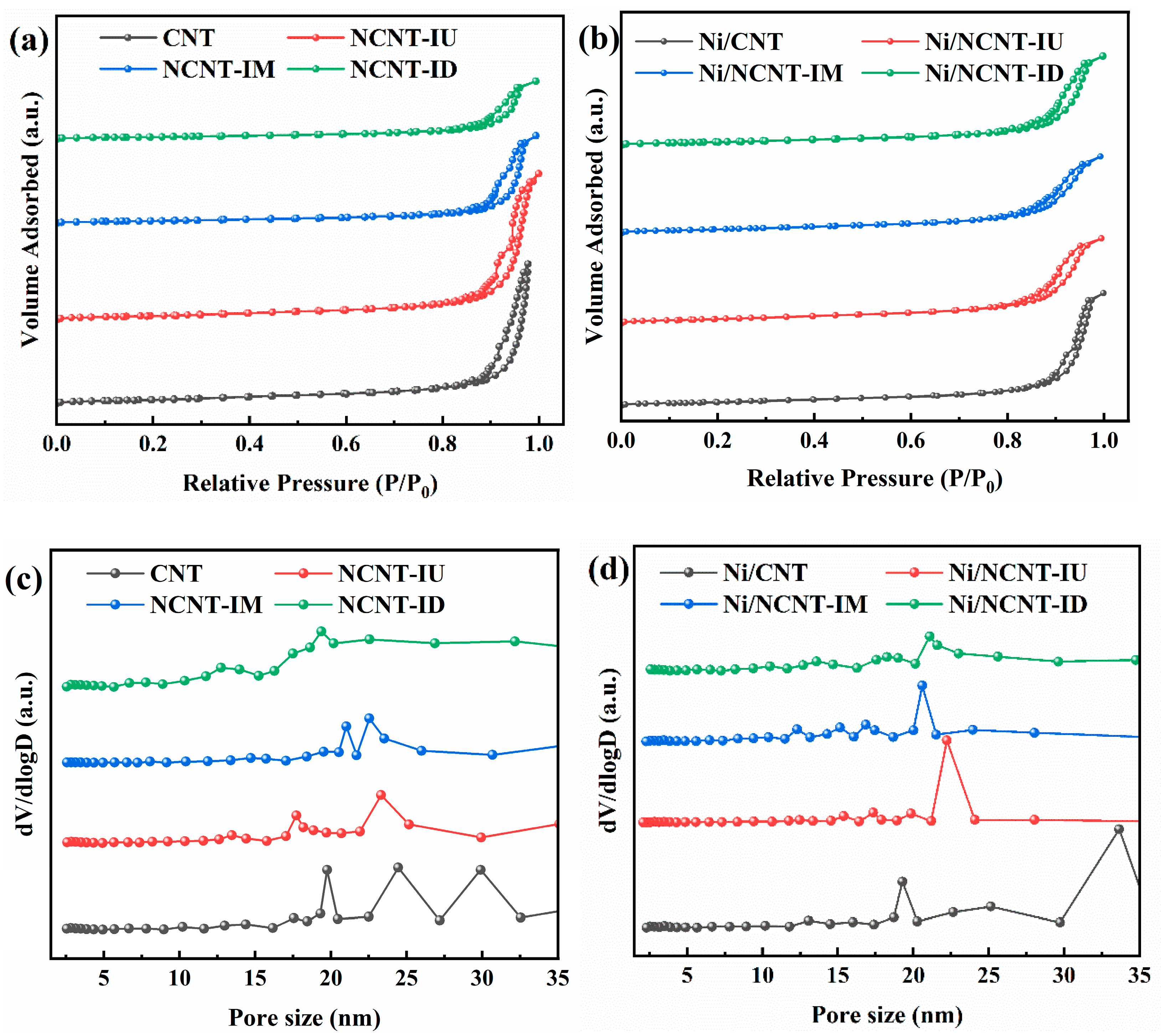
Figure 1. FTIR spectra from 500 to 4000 cm−1 of all supports (IM: impregnated melamine; IM: impregnated urea; ID: impregnated dicyandiamide; BU: ball-milling urea; GU: grinding urea).
Catalysts 15 00559 g001
Figure 2. (a) N2 adsorption–desorption isotherms measured for the pristine CNT and NCNT; (b) N2 adsorption–desorption isotherms measured for the Ni/CNT and Ni/NCNT; (c) pore size distribution obtained using the BJH desorption for the pristine CNT and NCNT; (d) pore size distribution obtained using the BJH desorption for the pristine Ni/CNT and Ni/NCNT.
Catalysts 15 00559 g002
Figure 3. (a) XRD patterns of the Ni/CNT and Ni/NCNT catalysts; (b) H2-TPR patterns of the Ni/CNT and Ni/NCNT catalysts.
Catalysts 15 00559 g003
Figure 4. (a) N 1s XPS spectra of Ni/CNT and Ni/NCNT catalysts; (b) Ni 2p XPS spectra of Ni/CNT and Ni/NCNT catalysts.
Catalysts 15 00559 g004
Figure 5. TEM micrographs of (a) Ni/CNT and (c) Ni/NCNT-IU, and particle size distribution histograms of (b) Ni/CNT and (d) Ni/NCNT-IU.
Catalysts 15 00559 g005
Figure 6. (a) N2 adsorption–desorption isotherms measured for the NCNT-BU and NCNT-GU; (b) N2 adsorption–desorption isotherms measured for the Ni/NCNT-BU and Ni/NCNT-GU; (c) pore size distribution obtained using the BJH desorption for the NCNT-BU and NCNT-GU; (d) pore size distribution obtained using the BJH desorption for the Ni/NCNT-BU and Ni/NCNT-GU.
Catalysts 15 00559 g006
Figure 7. (a) XRD patterns of the Ni/CNT and Ni/NCNT catalysts, (b) Raman patterns of the Ni/CNT and Ni/NCNT catalysts, and (c) H2-TPR patterns of the Ni/CNT and Ni/NCNT catalysts.
Catalysts 15 00559 g007
Figure 8. (a) N 1s XPS spectra of Ni/NCNT-BU and Ni/NCNT-GU catalysts; (b) Ni 2p XPS spectra of Ni/NCNT-BU and Ni/NCNT-GU.
Catalysts 15 00559 g008
Figure 9. DRM activity of different catalysts, GHSV = 18,000 mLgcat−1h−1 and CH4/CO2 = 1, on (a) CH4 conversion activity, (b) CO2 conversion activity, and (c) H2/CO ratio. (In the diagram, IU stands for Ni/NCNT-IU, and so on.).
Catalysts 15 00559 g009
Figure 10. DRM stability of different catalysts at 800 °C for 24 h; GHSV = 18,000 mLgcat−1h−1 and CH4/CO2 = 1 (a); (b) CO2 conversion stability; (c) H2/CO ratio.
Catalysts 15 00559 g010
Figure 11. (a) XRD patterns; (b) Raman spectra of spent catalysts; (c,e) TG and (d,f) DTG curves of spent catalysts.
Catalysts 15 00559 g011
Table 1. Pore structure parameters of supports and catalysts.
SamplesSBET (m2/g) aVp (cm3/g) bda (nm) b
CNT254.92.0222.3
NCNT-IU241.62.0521.5
NCNT-IM144.21.2420.6
NCNT-ID126.30.8118.8
Ni/CNT243.81.6019.7
Ni/NCNT-IU268.11.2313.8
Ni/NCNT-IM238.21.1113.8
Ni/NCNT-ID211.91.2316.9
a: Estimated using N2 physisorption; b: estimated using BJH desorption model.
Table 2. Pore structure parameters of supports (NCNT-BU and NCNT-GU) and catalysts (Ni/NCNT-BU and Ni/NCNT-GU).
SamplesSBET (m2/g)Vp (cm3/g)da (nm)
NCNT-BU239.61.7420.3
NCNT-GU239.91.8221.7
Ni/NCNT-BU243.61.3817.4
Ni/NCNT-GU253.51.5618.2
Disclaimer/Publisher’s Note: The statements, opinions and data contained in all publications are solely those of the individual author(s) and contributor(s) and not of MDPI and/or the editor(s). MDPI and/or the editor(s) disclaim responsibility for any injury to people or property resulting from any ideas, methods, instructions or products referred to in the content.

