Article

Effects of Ammonia Solution and Pyrolysis Gas on NOx Emission from a 75 t/h Pulverized Coal Boiler

1
Institute of Thermal Energy Engineering, School of Mechanical Engineering, Shanghai Jiao Tong University, Shanghai 200240, China
2
Ural Institute, North China University of Water Resource and Electric Power, Zhengzhou 450045, China
3
School of Environment and Architecture, University of Shanghai for Science and Technology, Shanghai 200093, China
*
Author to whom correspondence should be addressed.
Catalysts 2022, 12(2), 141; https://doi.org/10.3390/catal12020141
Submission received: 30 December 2021 / Revised: 17 January 2022 / Accepted: 19 January 2022 / Published: 24 January 2022

Abstract

:
To explore methods of reducing NOx emission from pulverized coal boilers, the effects of injecting ammonia solution and pyrolysis gas into the furnace on NOx emission were experimentally investigated on a 75 t/h pulverized coal boiler. Results show that the deep air staging with 30% separated over fire air (SOFA) creates a high temperature and strong reducing atmosphere in the reducing zone, providing the prerequisites for NOx reduction by ammonia solution and pyrolysis gas. Compared with deep air staging itself, NOx emission can be reduced by 16.7% when ammonia solution is injected from the reducing zone with a normalized stoichiometric ratio of 2.0. However, NOx reduction efficiency is largely affected by its injection position. Similarly, NOx emission is decreased by 28.2% through injecting pyrolysis gas with its calorific value of 10% into the furnace, while a further increase of pyrolysis gas input will not increase NOx reduction efficiency. When ammonia solution and pyrolysis gas are simultaneously injected into the furnace under deep air staging conditions, the overall NOx reduction efficiency reaches 92.0% and NOx emission is decreased to 39.1 mg/m3. Considering the increasingly strict NOx emission standard, these findings can provide theoretical and practical guides to the future NOx reduction in pulverized coal boilers.

1. Introduction

The extensive use of fossil fuels has been the powerful engine to promote the rapid development of the global economy, but their combustion process produces a large amount of air pollutants, and NOx is one major concern of them [1,2]. To reduce the harmful effects caused by NOx emission from fossil fuel combustion, many countries increase the proportion of renewable and clean energy sources. However, for developing countries like China and India where fossil fuel, especially coal is still the dominant energy source [3,4], NOx emission is inevitable and is still the major concern. Considering this, a new NOx emission national standard that requires NOx emission from coal-fired boilers should not be greater than 50 mg/m3 has been applied in China since 2014 [5], which is much stricter than that of 100 mg/m3 in the previous standard. However, the use of low-NOx combustion technologies such as horizontal bias combustion, air/fuel staged combustion and flue gas recirculation can no longer meet this requirement. So, these low-NOx combustion technologies are always used in combination with flue gas denitrification methods, including selective non-catalytic reduction (SNCR) [6,7] and selective catalytic reduction (SCR) technologies [8,9]. Nevertheless, SCR technology is characterized with problems of high operating cost caused by catalyst deactivation, low-temperature corrosion of air preheater tubes and secondary air pollution caused by ammonia escape, while SNCR encounters problems like low NOx reduction efficiency and narrow temperature window for NH3/NO reduction reaction [10,11,12]. Consequently, it is urgent to explore more effective and low-cost NOx reduction methods for coal-fired boilers.
In pulverized coal boilers, NOx is believed to mainly come from fuel NOx, accounting for 80–90% of the total NOx content [13,14]. After being heated inside the furnace, the coal particle devolatilization process quickly begins and part of fuel-N is released together with the volatiles in the forms of N-intermediates, like NH3 and HCN [15,16]. Thereafter, N-intermediates are consumed by competitive reaction pathways. In an oxidizing atmosphere, N-intermediates are mainly oxidized to produce NO and N2O, while in a reducing atmosphere, they tend to be reduced to N2 or react with the generated NO [17,18]. The rest of fuel-N remains in char species in the form of char-N, and most of char-N will be converted into NO during the char combustion process, and a small amount of it is believed to react with reducing agents (NH3, CH4, CO, etc.) to produce N2 in reducing atmosphere [19]. Therefore, the conversion of fuel-N and the formation of fuel-NOx in pulverized coal boilers are significantly dependent on the local combustion conditions, i.e., the redox atmosphere and the contents of reducing agents.
Through experimental investigation carried out in a flow reactor at 1100 °C condition, Hasegawa et al. [20] found that the oxygen content significantly affects the conversion of NH3, and the decrease of oxygen content is conducive to preventing NH3 from being oxidized. Bose et al. [21] investigated the formation and reduction mechanisms of NOx in the oxygen-lean and fuel-rich zone and found that the contents of reducing N-intermediates (NH3 and HCN) are higher in the reductive combustion atmosphere and thus NOx reduction efficiency is increased. Javed et al. [22] further explored the reaction mechanisms of NH3/NO/O2 system through kinetic analysis and reported that NOx content can be reduced by urea and ammonia solution in high temperature and reducing combustion atmosphere, and NH3 will not be oxidized at the same time. Similarly, based on experimental work on an electric heating furnace, Spliethoff et al. [23] found that increasing the temperature and enhancing the reducing atmosphere promoted NH3/NO reduction reaction. Yue et al. [24] focused on the injection of NH3 into coal combustion zone on the final NOx emission from coal fired boilers and found that the low stoichiometric ratio in the main combustion region creates a reductive atmosphere, and the injection of urea solution can effectively reduce NOx emission with a maximum NOx reduction efficiency of 94.1%.
Although many studies have proved that adding reducing agents into the combustion region or NOx-containing flue gas can effectively reduce the final NOx emission, these studies are mainly based on laboratory-scale test facilities or pure mechanism analysis. Since the in-furnace aerodynamics and coal combustion behavior are more complicated in practical pulverized coal boilers, the local combustion atmosphere and the mixing degree of reducing agent and generated NOx are quite different from that in lab-scale test rigs. Therefore, the applicability of theoretical analysis and lab-scale experimental results to the complicated combustion conditions in practical boilers needs to be further investigated. Besides, due to the greatly varied combustion conditions inside the pulverized coal boiler furnace, the optimal injection position and amount of reducing agents should also be further confirmed.
To solve the abovementioned problems, an experimental investigation of injecting ammonia solution and pyrolysis gas into the reducing zone is carried out on a 75 t/h pulverized coal boiler to see their influences on NOx emission. Based on the high temperature and reducing atmosphere created by deep air staging, the effects of injection position of ammonia solution and its normalized stoichiometric ratio, and the calorific ratio of pyrolysis gas input on NOx reduction efficiency were thoroughly discussed. Results show that the injection of ammonia solution or/and pyrolysis gas into high-temperature and reducing regions can further reduce NOx emission when compared with deep air staging itself, and the maximum combined NOx reduction efficiency can be as high as 92.0% under optimal combustion scenario. However, the injection position and amount of reducing agents should be carefully controlled to prevent them from being oxidized into NO. These findings reveal the effective denitrification effects of injecting reducing agents into proper regions in practical pulverized coal boiler, which provides theoretical and technical guides to power plants for further NOx emission reduction under the increasingly strict NOx emission standard.

2. Results and Discussion

This work aims to explore the effects of adding pyrolysis gas and ammonia solution into the reductive combustion zone on NOx reduction efficiency in a practical pulverized coal boiler. To this end, distribution profiles of in-furnace combustion temperature and gas components under air staging conditions are firstly measured to explore the suitable air staging condition for pyrolysis gas and ammonia solution injection. Thereafter, denitrification effects of injecting ammonia solution, pyrolysis gas, and their combination are investigated respectively. The results will be thoroughly presented and discussed in the following parts.

2.1. Effects of Air Staging on NOx Formation Characteristics

To avoid the possibility of being oxidized and to achieve the best NOx reduction performance, the reducing species (pyrolysis gas and ammonia solution) should be injected into the furnace under high-temperature and reducing atmosphere [24,
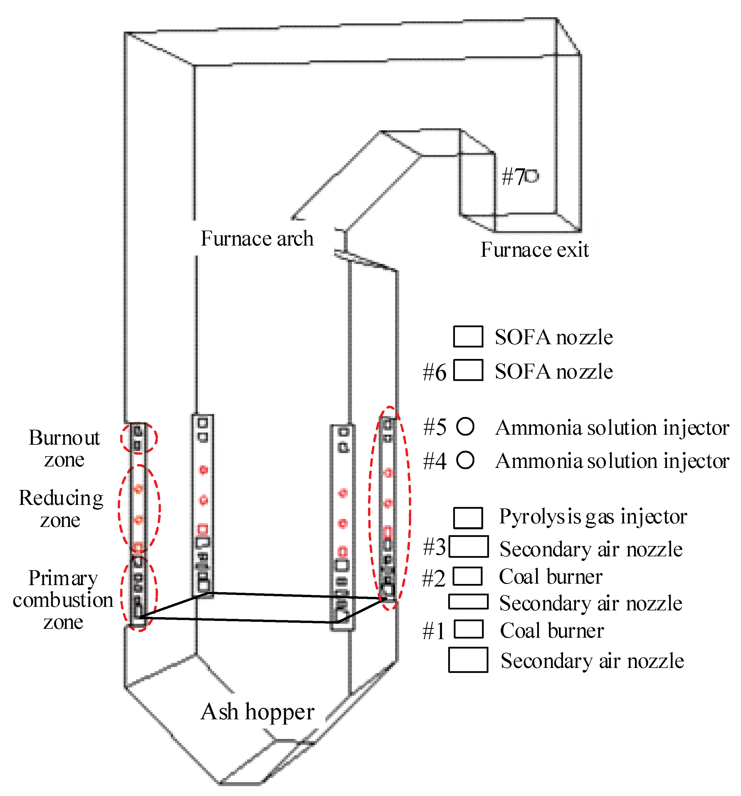
25]. Therefore, influences of SOFA ratio on in-furnace combustion atmosphere are firstly studied, and 
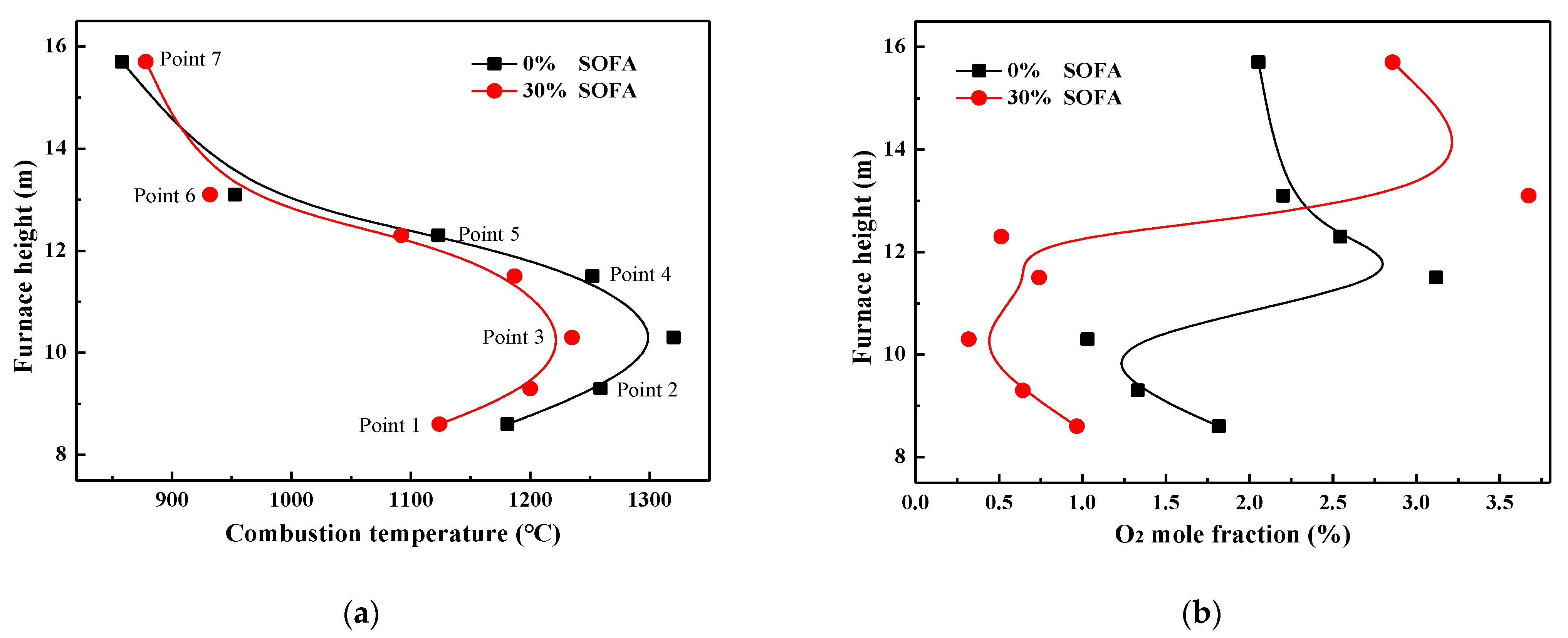
Figure 1 presents the profiles of combustion temperature and O2 mole fraction under various SOFA ratio combustion scenarios. It should be noted that data points in Figure 1 are the average parameter values measured at each certain furnace height. It can be told that temperature distribution patterns are very similar in 0% and 30% SOFA ratio cases, where combustion temperature is very low at the furnace bottom and then is increased evidently in the primary combustion zone due to the intense combustion process. With the continuous increase of furnace height, the share and intensity of the coal combustion process decrease, so that the continuous heat absorption of water-tube walls leads to a gradual decrease of temperature level. In consistent with combustion temperature, oxygen content is lowest in the primary combustion zone because of its consumption and then increases in the SOFA zone due to the input of SOFA air and the decreased coal combustion intensity.
Compared with a combustion scenario without air staging, the in-furnace combustion temperature under 30% SOFA condition decreases evidently, as the average temperature at the height of measuring point 3 is 95 °C lower. Meanwhile, the residual oxygen content decreases obviously under large SOFA ratio cases, as it can be seen that the average O2 mole fraction in 8.5–12.3 m of 30% SOFA ratio case is decreased about 0.70–0.85% when compared with 0% SOFA ratio case. This can be attributed to the fact that when 30% combustion air is introduced into the furnace from the SOFA region, the total oxygen input in the primary combustion zone is decreased, and thus coal combustion process here undergoes an oxygen-deficient condition, resulting in decreases in combustion heat release and combustion temperature. However, it can be seen that under 30% SOFA ratio condition, temperature values between measuring points 2–4 are still higher than 1200 °C, and the oxygen content is lower than 0.75% in this region at the same time. That is to say, 30% SOFA ratio creates a high-temperature reducing atmosphere below the SOFA region, which is conducive to the injection of pyrolysis gas and ammonia solution for the denitrification process.
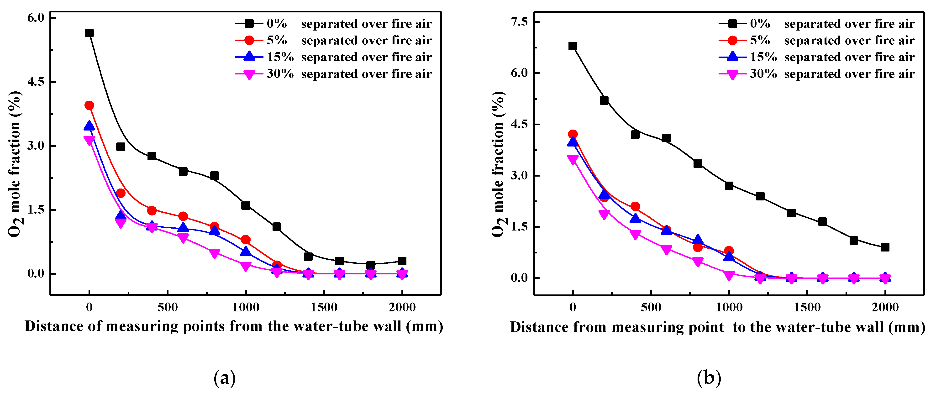
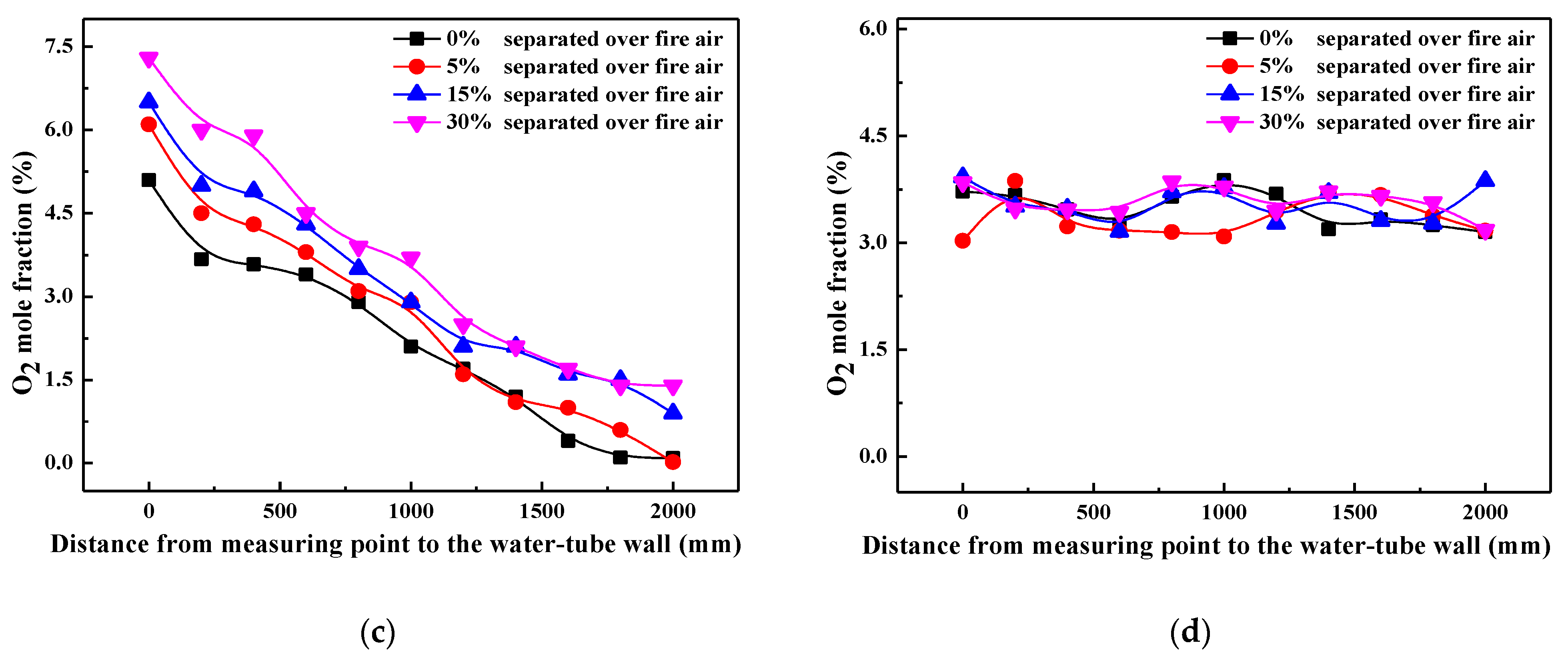
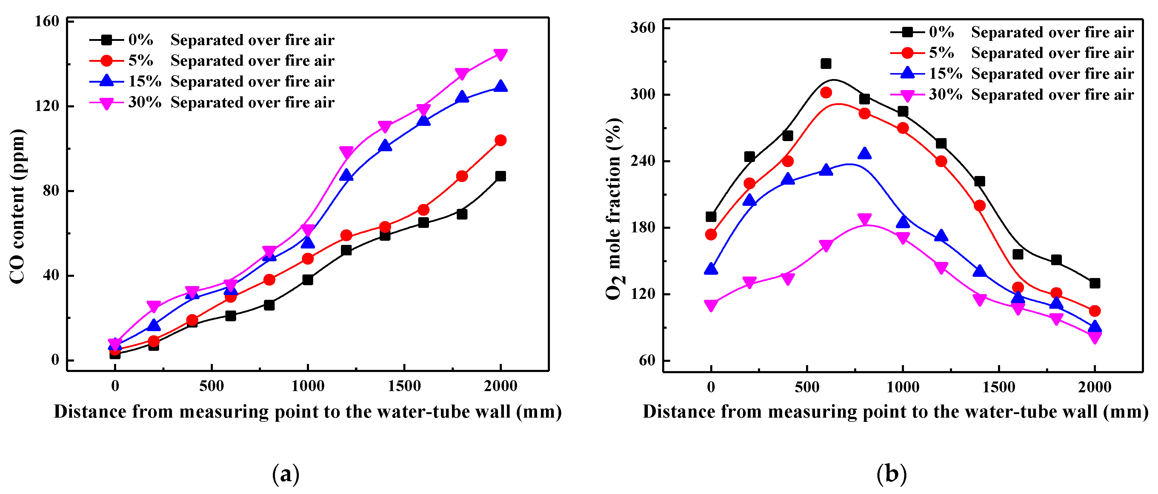
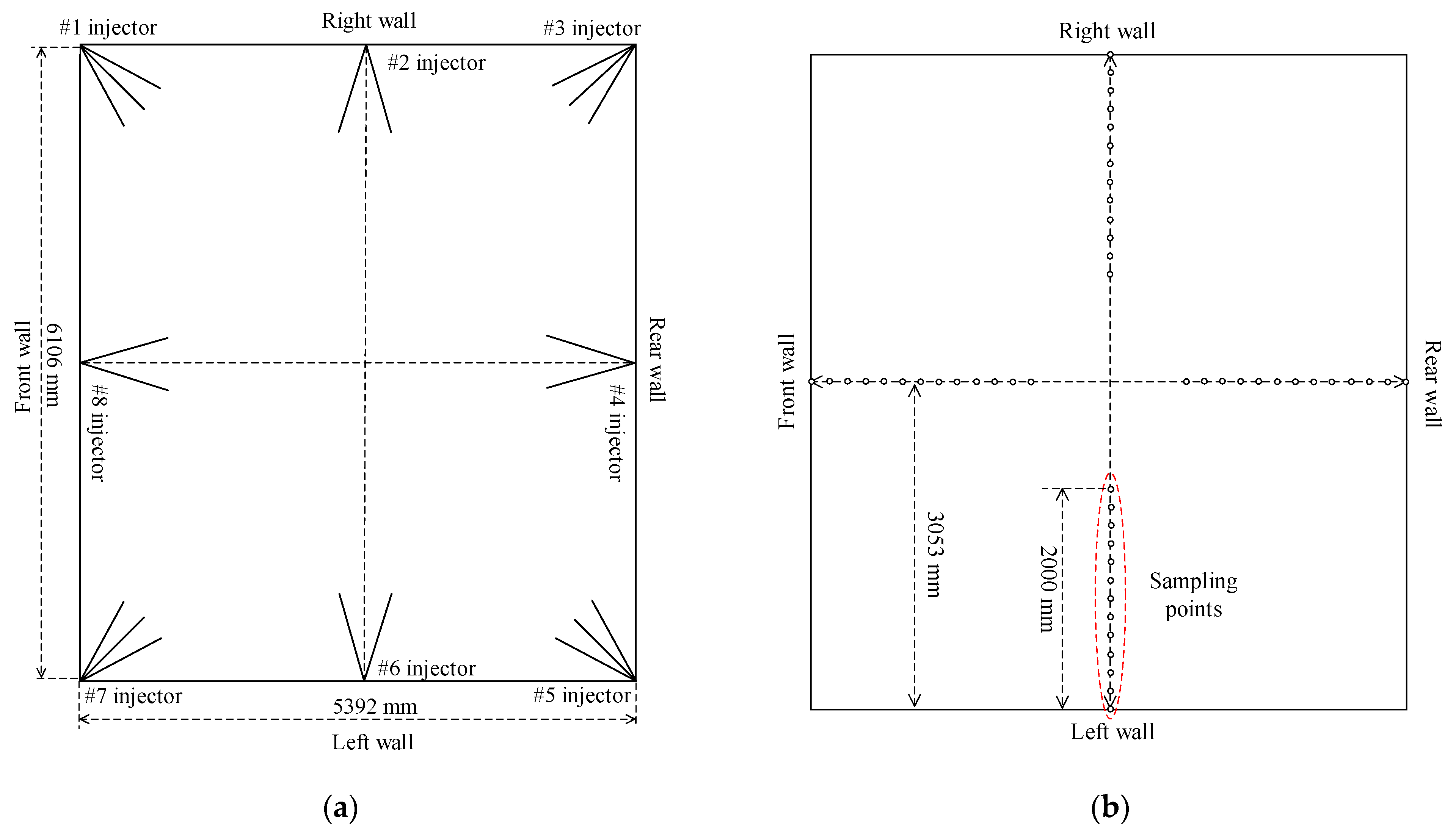
In order to characterize the influence of air staging on combustion atmosphere in detail, oxygen mole fractions along the axis of reducing agent injectors are measured at each measuring point height, and their values are illustrated in Figure 2. For simplification, only oxygen content measured from point 2 (primary combustion zone), point 4 (reducing zone), point 6 (SOFA zone), and point 7 (furnace exit) are plotted in this work. It can be found that with the SOFA ratio increasing, oxygen content in the near-wall region decreases evidently in the primary combustion zone and reducing zone, and oxygen content differences among various SOFA ratio cases decrease with the increase of furnace depth. This demonstrates that the introduction of SOFA can reduce the oxidizing atmosphere in the near-wall region, which thus creates a larger reducing area inside the furnace. On the contrary, since more oxygen is introduced into the furnace from the SOFA region, oxygen content in the SOFA region (point 6) increases gradually when the SOFA ratio is increased, which guarantees the continued combustion of incompletely burned coal particles. Considering the fluctuation of measured data over time, it can be reckoned from Figure 2d that there are no essential differences in oxygen contents at the furnace exit under various SOFA ratio cases. That is to say, 30% SOFA ratio helps to create a large reducing area below the SOFA region to promote NOx reduction when reducing agents are injected, and coal combustion efficiency will not be obviously decreased at the same time.
To further explore the effects of air staging itself on NOx generation, Figure 3 shows the variation of CO and NOx contents along the axis of reducing agent injectors at measuring point 6. As can be seen with the increase of SOFA ratio, CO content above SOFA region increases gradually while NOx content decrease evidently. This is ascribed to the fact that when air staging is adopted, the availability of oxygen content in the primary combustion zone is decreased so that more CO is produced during the oxygen-deficient coal combustion process. Meanwhile, instead of being oxidized to NO, the released N-intermediates (NH3 and HCN) during the coal combustion process under oxygen-lean conditions are more likely to be reduced N2, as R1 depicts. Therefore, in pulverized coal boiler where NOx mainly comes from fuel type NOx, the initial NOx content generated during the combustion process decreases with the SOFA ratio increasing. Furthermore, although oxygen content in the SOFA region increases under large SOFA ratio cases, the amount of N-intermediates released here is evidently lower because of the small coal combustion share. In addition, the content of reducing CO is also higher, so that NOx content will not obviously re-increase during the post-combustion process in the SOFA region. Therefore, NOx content above SOFA region decreases with the increase of SOFA ratio, and the furnace exit NOx emission decreases from 400.1 mg/m3 in 0% SOFA ratio case to 215.5 mg/m3 in 30% SOFA ratio case.
4NH3 + 4NO + O2 = 4N2 + 6H2O
4NH3 + 5O2 = 4NO + 6H2O
CO + OH = CO2 + H
H + H2O = OH + H2
H + NH3 = NH2 + H2
In conclusion, air staging itself effectively reduces NOx generation and its final emission. Besides, a high-temperature and reducing atmosphere can be created below the SOFA region, which is believed to be conducive to maximizing the reduction effect of injected ammonia solution and pyrolysis gas. To verify this, the effects of injected ammonia solution and pyrolysis gas on NOx reduction efficiency under deep air staging conditions will be discussed.

2.2. Effects of Ammonia Solution Injection in Reducing Zone on NOx Formation

Although deep air staging itself can effectively reduce NOx emission, the contents of reducing N-intermediates (NH3 for example) released during the coal combustion process are relatively low, which limits their reduction effects on the generated NOx. To enhance the NOx reduction process under the high-temperature and reducing combustion atmosphere created by deep air staging, additional ammonia solution was injected into the furnace to increase NH3 content in the reducing zone and thus to promote the NOx reduction process. To evaluate the NOx denitrification effect of ammonia solution injection, 
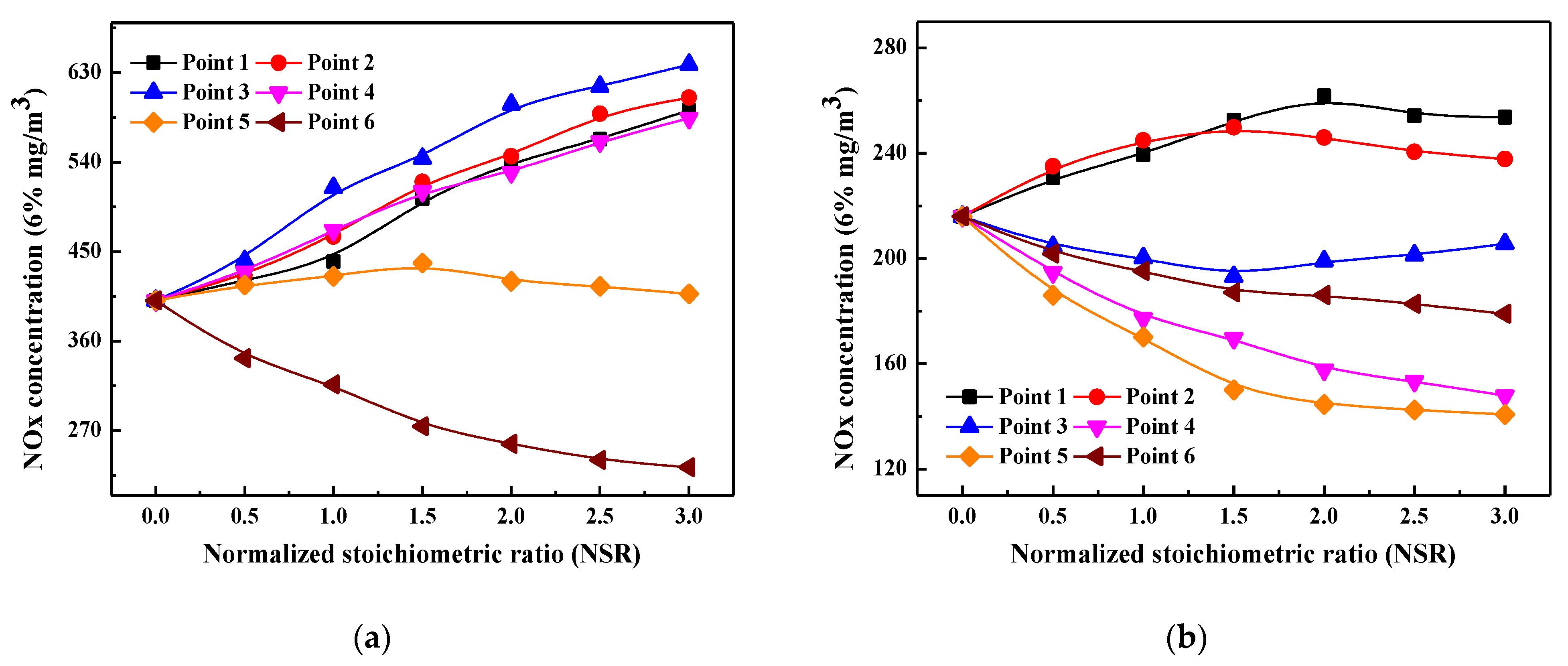
Figure 4 presents the variations of furnace exit NOx emission and the corresponding NOx reduction efficiency under combustion scenarios with different ammonia injection positions and NSR values. It is noteworthy that NOx emission values are normalized to 6% O2 condition, and the negative NOx reduction efficiency means that the injected ammonia solution is oxidized and results in an increase in furnace exit NOx emission.
It can be seen from Figure 4a that without air staging, the furnace exit NOx emission increases when ammonia solution is injected into the furnace from points 1–4. Figure 1b shows that oxygen content in the area between measuring points 1 to 4 is all higher than 1.0%, and it is as high as 3.1% at point 4. Meanwhile, except for point 1, the average temperature in this region falls in the range of 1180–1310 °C. In other words, the region between point 1 and point 4 is in a high-temperature and oxidizing atmosphere when SOFA is not adopted, so the injected ammonia solution is more likely to be oxidized to NOx instead of reacting with the generated NOx. Therefore, the furnace exit NOx emission increases after ammonia solution injection and the increased NSR value further promotes its oxidization. When ammonia solution is injected from point 5, NOx emission increases slightly and then decreases slowly with the continuous increase of NSR. This is attributed to that combustion temperature and oxygen content are still high here, so the injected ammonia solution is more likely to be oxidized when NSR is slightly increased, and thus NOx emission increases. However, when NSR is largely increased, the amount of injected ammonia solution increases evidently and part of the un-oxidized ammonia solution rises upwardly with the flue gas, which enters the region that falls within the temperature window of SNCR and then reacts with the generated NOx. Therefore, NOx emission decreases slightly when NSR exceeds 1.5. Since the further decreased temperature at point 6 makes it suitable for the SNCR denitrification process, the injected ammonia solution is not likely to be oxidized but more involved in NH3/NO reduction process. Therefore, NOx emission decreases with the increase of NSR when ammonia solution is injected from point 6. However, it should be noted that point 6 is very close to the furnace exit, so the reaction time for NH3/NO is insufficient and may result in high content of NH3 slip.
Figure 4b presents the distributions of NOx emission and its reduction efficiency after injecting ammonia solution under 30% SOFA ratio condition, which is obviously different from that of an un-staged combustion scenario. When ammonia solution is injected from points 1 and 2, furnace exit NOx emission increases at first and then decreases with the continuous increase of NSR. As can be seen from Figure 1b that O2 mole fraction at point 1 reaches 1%, so the small amount of ammonia solution injected into the furnace is easy to be oxidized into NOx, resulting in an increase in the final NOx emission. However, when NSR continues to increase, part of the un-oxidized ammonia solution enters the region where oxygen content is as low as 0.6% (point 2), so the un-oxidized ammonia solution participates in NH3/NO reaction process and slightly decrease the furnace exit NOx emission. Similarly but more obviously, the small amount of ammonia solution injected from point 2 is likely to be oxidized into NOx, but more of it participates in the NH3/NO reduction reaction when NSR is enlarged so that NOx emission increases at first and then decreases with NSR increasing. Different from that of points 1 and 2, when ammonia solution is injected from point 3, NOx emission decreases at first and then increases gradually with the continuous increases of NSR. As Figure 1b depicts, oxygen content at point 3 is especially low (0.3%), the injected ammonia solution can be quickly converted into NHi and then mix well with flue gas to reduce the generated NOx. However, when NSR continues to increase, the excessively injected ammonia solution no longer reacts with the generated NOx, instead, part of it is oxidized as the flue gas rises upward to oxygen-rich zone, and thus NOx emission increases when NSR is further enlarged.
Comparatively, when ammonia solution is injected from points 4 and 5, the furnace exit NOx emission decreases monotonously with the increase of NSR, and the maximum NOx reduction efficiency reaches 31.6% and 34.8% at NSR = 3.0 condition, respectively, when compared with no ammonia solution injection scenario. As aforementioned, a high-temperature and reducing combustion atmosphere is created in the area around points 4 and 5 under 30% SOFA ratio condition, so the injected ammonia solution is very like to react with the generated NOx as reactions (6)–(9) show [25,26]. Besides, the existence of a large amount of reducing agents prevents the oxidation of released N-intermediates, so NOx emission obviously decreases when ammonia solution is injected from points 4 and 5. Although NOx emission is also decreased with NSR increasing when ammonia solution is injected from point 6, its amplitude is smaller than that of points 4 and 5. This is ascribed to the fact that oxygen content at point 6 is significantly increased due to SOFA injection, which thus decreases the reduction efficiency of injected ammonia solution. However, in the process of moving upwardly with flue gas, the unreacted ammonia solution enters the region with suitable temperature and oxygen content of SNCR denitrification process, so that ammonia solution reacts with the generated NOx through SNCR mechanism and thus NOx emission is reduced. Furthermore, it can be inferred from the above analysis that injecting ammonia from the high-temperature and reducing zone (points 4 and 5) is superior to that of SCNR mechanism in terms of NOx denitrification effect.
NH3 + OH (O) = NH2 + 6H2O
NH2 + NO = NNH + OH
NH2 + NO = N2 + H2O
NNH = N2 + H
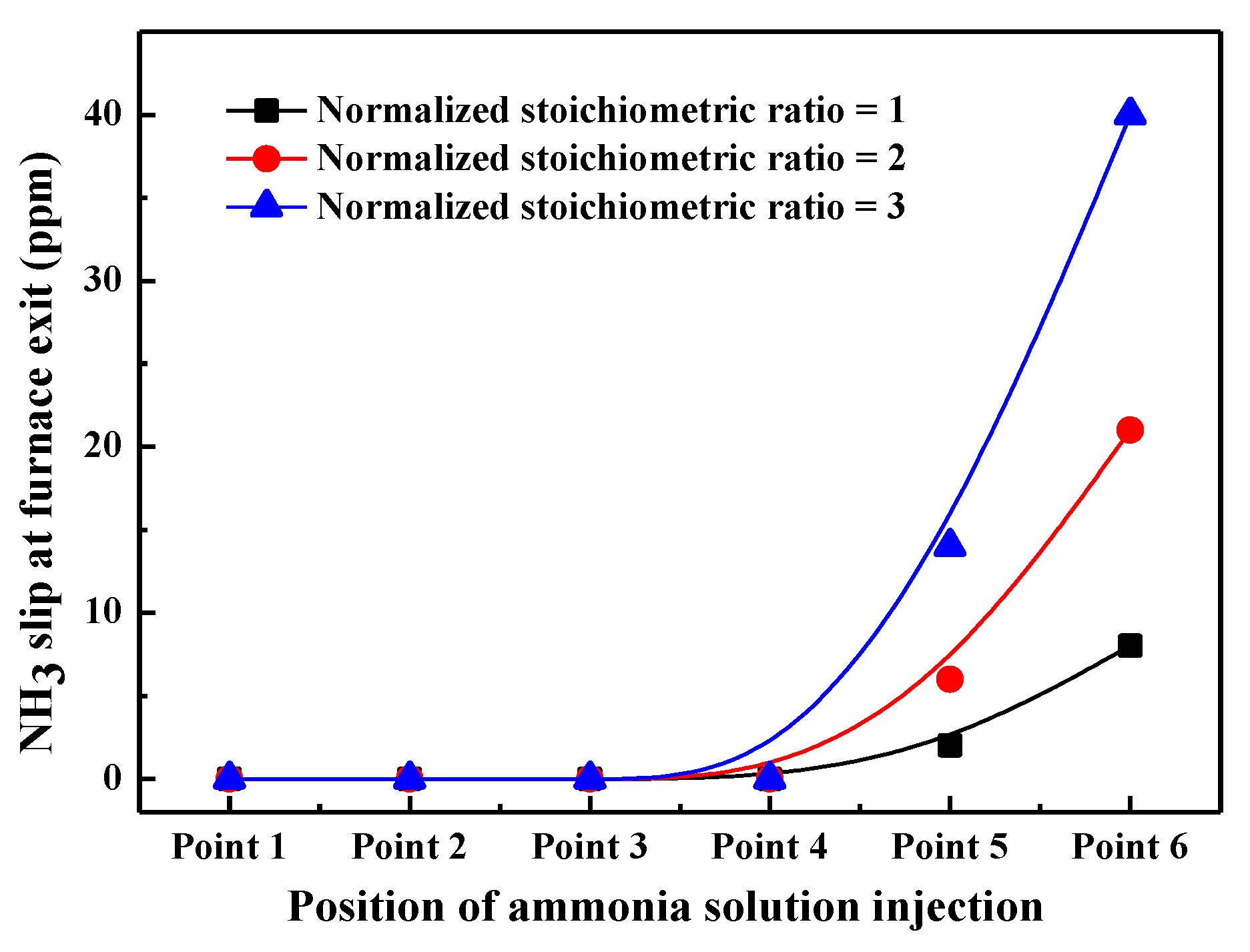
The above results show that the denitrification effects of ammonia solution vary with its injection position, and NOx emission can be further reduced on the basis of deep air staging if ammonia solution is injected through appropriate locations (points 4–5). Besides, NOx reduction efficiency is increased with the increase in amount of ammonia solution (NSR). However, NH3 slip from the furnace may result in secondary air pollution and severe corrosion problem on the rear heating surfaces in practical boiler. To avoid this, NH3 slip at the furnace exit is measured when ammonia solution is injected into the furnace, as shown in Figure 5.
It can be seen that there is almost no NH3 slip detected at the furnace exit when ammonia solution is injected from points 1–4, even though under large NSR conditions. This is attributed to the fact that points 1–4 are located at the middle and bottom parts of the furnace, so the injected ammonia solution has ample residence time to participate in the NH3/NO reduction process, and the unreacted ammonia solution can be totally oxidized during the subsequent combustion process. Therefore, there is almost no NH3 left the furnace exit. However, NH3 slip phenomenon at the furnace exit becomes more and more obvious when the position of ammonia solution injectors is higher. For instance, NH3 slip is as high as 42 ppm when ammonia solution is injected from point 6 and NSR is kept as 3.0, which is far higher than that of SNCR and SCR method [27,28]. This is because when being injected from a higher location, the residence time of ammonia solution in the proper reducing region is short, inhibiting the effectiveness of NH3/NO reduction reaction. Meanwhile, these unreacted NH3 cannot be completely oxidized to NOx due to the shortened residence time and decreased combustion temperature, so the amount of NH3 slip increases significantly with NSR increasing. In terms of NOx reduction efficiency and NH3 slip, ammonia solution should be injected into the furnace from point 4 and NSR should not be greater than 2.0 in this experiment.

2.3. Effects of Pyrolysis Gas and Its Combination with Ammonia Solution in Reducing Zone on NOx Emission

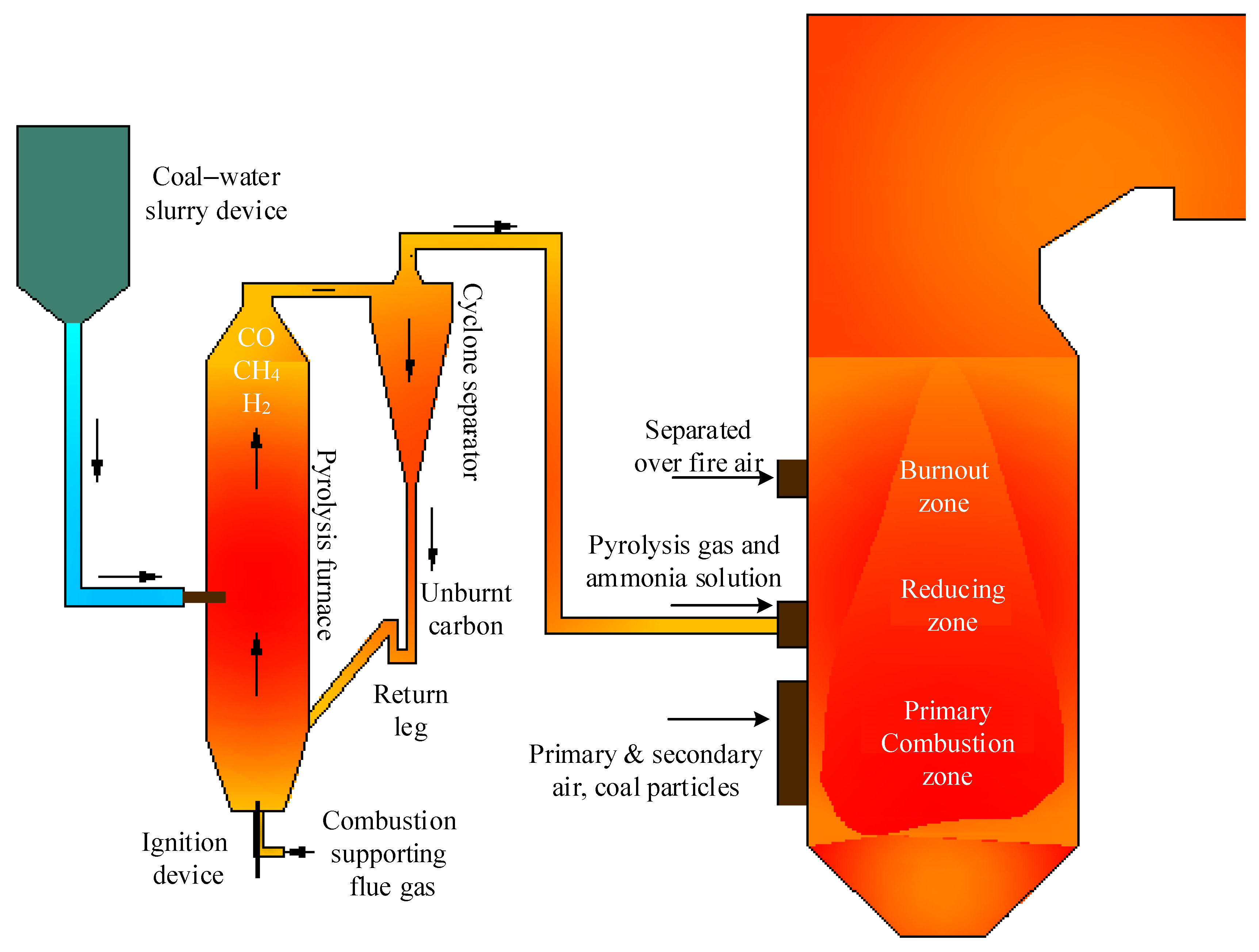
The above analysis demonstrates that injecting ammonia solution into the appropriate regions in the furnace can effectively reduce NOx emission. In fact, a certain amount of reducing components (CO, CHi, NH3, etc.) will be inherently produced during the pulverized coal combustion process, but their contents are too low to effectively promote the NOx reduction process. Given this, the effects of additional injection of pyrolysis gas with major components of CO, CH4, and H2 on NOx emission were investigated. 
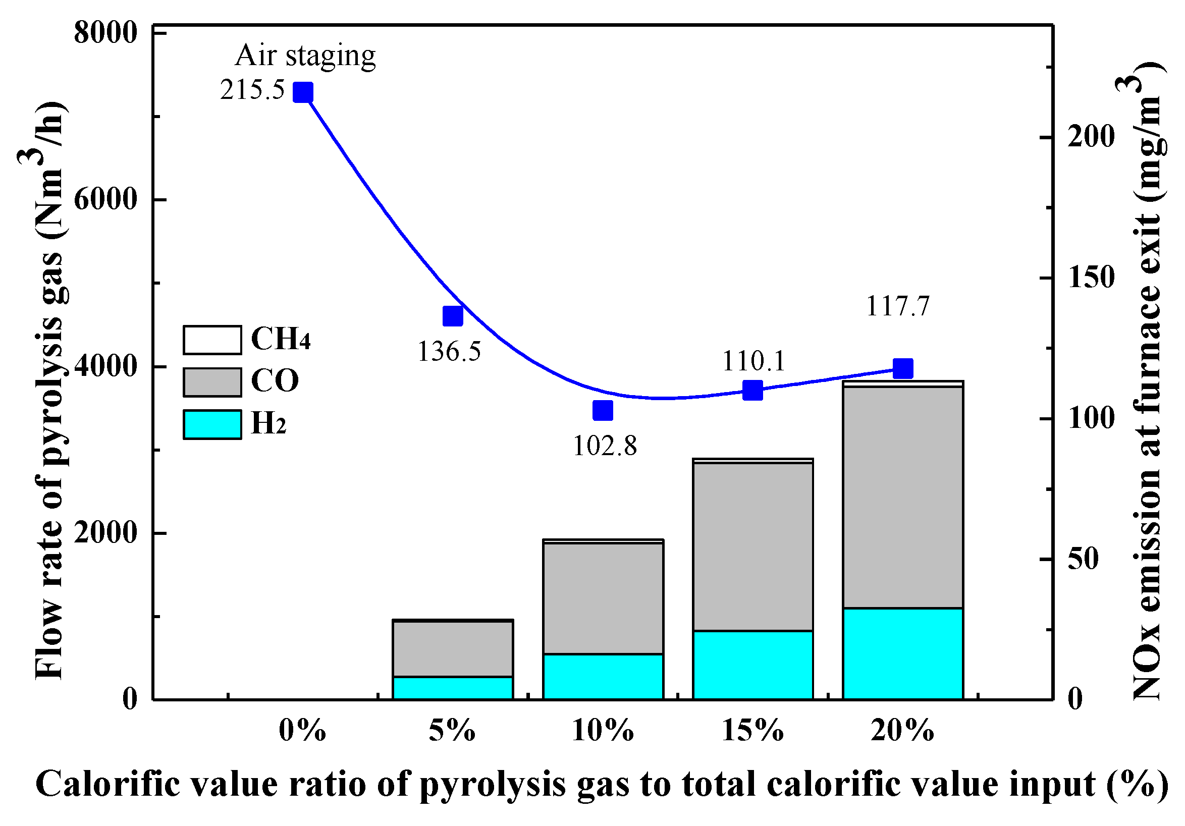
Figure 6 presents the variation of furnace exit NOx emission with the amount of pyrolysis gas input under 30% SOFA ratio condition, from which an evident decrease of NOx emission can be found after reducing pyrolysis gas is injected into the furnace. When the calorific value of pyrolysis gas accounts for 5% and 10% of the total calorific input of coal, the furnace exit NOx emission is decreased from 215.5 mg/Nm3 to 136.49 mg/Nm3 and 102.82 mg/Nm3 respectively. However, when the amount of pyrolysis gas is further increased, NOx emission is slightly increased. In the optimal combustion scenario with 10% pyrolysis gas, the final NOx emission can be further reduced by 52.06% when compared with the deep air staging condition.
NOx reduction mechanisms by pyrolysis gas are as follows. As can be seen from Figure 6 that CO content is highest in pyrolysis gas, so the injected pyrolysis gas helps to create a strong reducing combustion atmosphere inside the furnace, which inhibits the oxidation of N-intermediates released from the initial combustion stage. In addition, CH4 and H2 contents in pyrolysis gas can directly promote the reduction of generated NOx. In a reducing atmosphere, the presence of CH4 increases the concentration of hydrocarbon radicals, which then promotes the formation of HCN in the reducing zone. Subsequently, the generated HCN may react with the generated NOx to form N2, as depicted by reactions (10)–(14). Therefore, under the strong reducing atmosphere created by a large amount of CO, the presence of CH4 effectively promotes the NOx reduction process. H2 itself does not yield hydrocarbon radicals, but its reactions can produce large amounts of OH and H radicals under high-temperature conditions, and then these radicals participate in NOx reduction reactions. Therefore, the existence of H2 in pyrolysis gas also contributes to increasing NOx reduction efficiency.
CHi + NO = HCN
HCN + O = NCO + H
NCO + H = NH + CO
NH + H = N + H2
N + NO = N2 + O
However, when the calorific ratio of pyrolysis gas exceeds 10%, its promotion effect on the coal combustion process may become more and more obvious. In this case, the reducing gas components (CO, CH4, and H2) may be quickly burned after being injected into the furnace, so their reduction effects on the generated NOx decrease. Consequently, furnace exit NOx emission reaches its minimum level in the combustion scenario with pyrolysis gas calorific value of 10% and then increases again with the continuous increase in the amount of pyrolysis gas input.
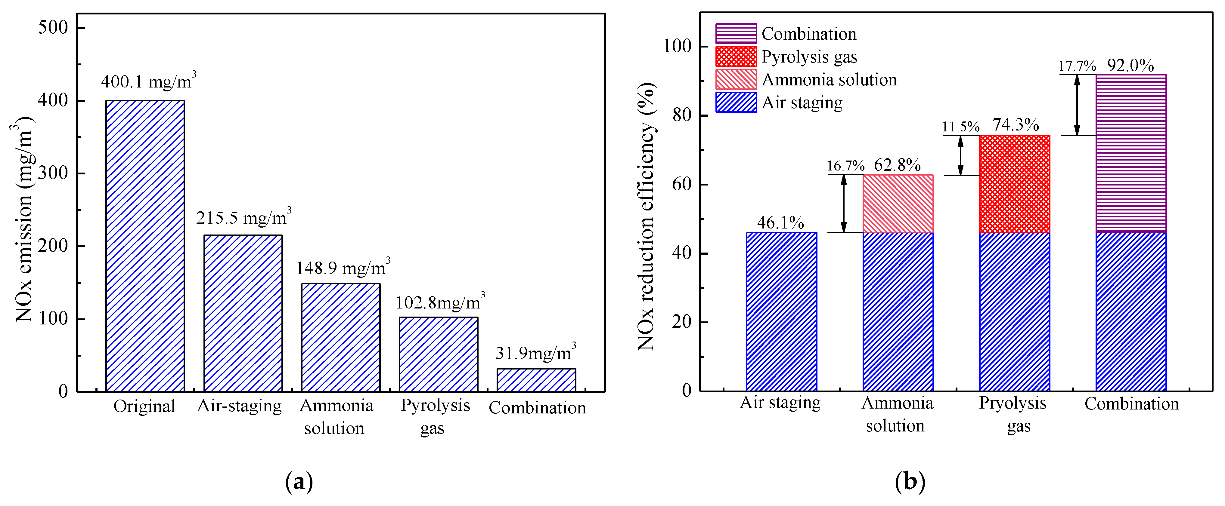
The influence of air staging, ammonia solution injection, pyrolysis gas injection, and their combination on furnace exit NOx emission and NOx reduction efficiency are further plotted in Figure 7. Compared with the benchmark combustion scenario without air staging, deep air staging with a 30% SOFA ratio itself can reduce NOx emission by 46.1%. Based on this, the injection of ammonia solution from point 4 with NSR of 2.0 further reduces NOx emission by 16.7%, and NOx emission at the furnace exit is decreased to 148.9 mg/m3. Similarly, when pyrolysis gas with 10% calorific value is solely injected into the furnace under 30% SOFA ratio condition, NOx emission can be reduced to 102.8 mg/m3 and NOx reduction efficiency is 28.2% higher than that of air staging itself. When ammonia solution and pyrolysis gas are simultaneously injected into proper furnace regions under deep air staging conditions, NOx emission can be significantly reduced to 31.9 mg/m3 and the combined NOx reduction efficiency is as high as 92.0% when compared with the non-staging condition. Therefore, it is concluded that the injection of ammonia solution and pyrolysis gas can effectively reduce NOx emission and their synergistic use is superior to each of them in terms of denitrification effect.
According to the above analysis, oxygen content in the primary combustion zone is significantly lowered under deep air staging conditions, which avoids the oxidation of released N-intermediates and thus decreases the initial NOx concentration generated from the coal combustion process. At the same time, the generated NOx can be partially reduced under the strong reducing combustion atmosphere, so that NOx emission can be effectively reduced by deep air staging itself. Based on the high-temperature and reducing combustion atmosphere created by deep air staging, the injection of ammonia solution significantly increases the contents of reductive NH3. Thereafter, NH3 is converted to NH2 and then it actively participates in the chain NOx reduction reactions to reduce NOx content. Similarly, the injection of pyrolysis gas greatly enhances the reducing atmosphere (CO) and the contents of reductive species (CH4 and H2) inside the furnace, which then promotes the conversion of N-containing species and generated NOx to N2 during the coal combustion process. When ammonia solution and pyrolysis gas are used together, the NOx reduction process can be significantly promoted, because the existence of a large amount of pyrolysis gas creates a stronger reducing atmosphere and the injection of ammonia solution increases the content of the reducing agent inside the furnace. Under the synergy of these methods, less fuel NOx is formed during the combustion process and more of the generated NOx can be effectively reduced, so NOx emission at the furnace exit is largely decreased.

3. Boiler Description and Experimental Methodology

3.1. Description of the Boiler Configuration and Experimental System

As Figure 8 shows, experiments were carried out on a 75 t/h corner-tangentially fired pulverized coal boiler with natural circulation and a single drum. Boiler steam parameters are 3.82 MPa and 450 °C at BMCR conditions, and the designed thermal efficiency is 90.24%. The furnace height from the bottom of the ash hopper to the furnace roof is 26.42 m, and the cross-section in the primary combustion zone is 5.39 × 6.11 m. As can be seen from Figure 8 pulverized coal burners and secondary air nozzles are arranged at four corners to form a tangent combustion circle with an imaginary diameter of 0.417 m. To enhance the mixing process of pulverized coal particles and the supplementary combustion air, coal burners and secondary air nozzles are installed at intervals in the primary combustion zone. Before carrying out the experiments, the boiler is retrofitted during which two layers of separated over fire air (SOFA) nozzles were amounted at several meters above the top coal burners, so as to deepen the air staging degree and thus SOFA ratio can be increased to 30% to create a strong reducing atmosphere in the main combustion region.
This experimental work aims to investigate the effects of reducing pyrolysis gas and ammonia solution and their combined effects on NOx transformation characteristics during the pulverized coal combustion process, and the injection system of pyrolysis gas is schematically illustrated in Figure 9. To generate the reducing pyrolysis gas, a coal–water slurry pyrolysis furnace that produces 5 t/h pyrolysis gas is built nearby the pulverized coal furnace, and the temperature inside the pyrolysis furnace is within the range of 800–1200 °C while the pressure is kept around 8 kPa. Coal–water slurry with a certain concentration is pressurized by a high-pressure pump and then sent into the pyrolysis furnace through the coal–water slurry nozzles arranged at the middle part of the pyrolysis furnace, and a swirl pulverized coal burner is located at the bottom of the pyrolysis furnace to provide the heat needed for the coal–water slurry pyrolysis process. Inside the pyrolysis furnace, the coal–water slurry is dried, and then its pyrolysis and char-H2O gasification processes occur. Thereafter, pyrolysis gas accompanied by part of small char particles is evacuated into the cyclone separator from the top of the pyrolysis furnace. Inside the cyclone separator, most of the char particles are separated from the pyrolysis gas and then being sent back into the pyrolysis furnace from the return leg, while pyrolysis gas and a small portion of fine char particles are driven into the boiler due to the slight positive pressure inside the pyrolysis furnace and the cyclone separator. Thereafter, pyrolysis gas and fine char particles are injected into the appropriate region inside the furnace to reduce the generated NOx during the coal combustion process.
Similarly, the injection system of ammonia solution consists of the storage, transport, and injection parts of ammonia solution is also built. For simplification, the storage unit for the ammonia solution is shared with that of the original SCR denitrification system, and its transport system is newly designed with stainless steel pipes and the ammonia solution is transported with a multistage centrifugal pump to lift its pressure. The injection system of ammonia solution is mainly composed of flow control valves and atomizing spray guns and the arrangement of ammonia solution injectors is shown in Figure 10a. In the area between the top secondary air nozzles and the bottom SOFA nozzles, 16 ammonia solution injection nozzles are set into two layers, where 8 of them are mounted at the corners and the furnace wall centerlines in each layer. The velocity of ammonia solution injection is designed to be 15 m/s to ensure that ammonia solution jets have enough stiffness to mix well with the flue gas. The designed residence time of pyrolysis gas and ammonia solution in the high-temperature reducing zone is 1 s, which provides ample time for the NOx reduction process.
During the experiments, the combustion temperature and gas components inside the furnace and NOx emission at the furnace exit are measured. Combustion temperature is determined by S-type thermocouples with a measurement range of 0–1500 °C and accuracy of 1.5 °C. Flue gas compositions and their contents are measured by a portable gas analyzer (Testo 340), and its measurement accuracy of NO, CO, and O2 contents is 5 ppm, 10 ppm, and 0.2%, respectively. The horizontal distribution of measuring points in the primary combustion zone is shown in Figure 10b, where thermocouples and sampling guns are inserted into the furnace from openings at the centerline of each furnace wall. The maximum extension distance of thermocouples and sampling gun is 2.0 m and parameters are measured every 0.2 m so that 11 values of each parameter can be obtained from a measuring opening. As depicted in Figure 10b, the measuring points reach 2/3 of the furnace width and depth, so the measured values reflect the distribution of these parameters inside the furnace. As can be seen from Figure 8, 6 layers of measuring points are arranged in the coal combustion zone, and the average of measured values on each furnace height is used to characterize the variations of combustion parameters along the furnace height. Similarly, NOx emission at the furnace exit is measured by Testo 340 along the depth of the flue gas tunnel at measuring point 7.

3.2. Boundary Conditions and Cases Set Up

NOx reduction experiments under the effects of pyrolysis gas and ammonia solution were conducted under 72 t/h boiler load conditions, which consumed 9.65 t/h bituminous coal. Properties of used coal are listed in Table 1, including the proximate analysis based on the as-received basis (ar) and the ultimate analysis based on the dry-ash-free basis (daf), where LHV represents the lower heating value of coal.
To analyze the effects of pyrolysis gas and ammonia solution injection into the high-temperature reducing zone on NOx reduction efficiency, 5 cases or case groups are designed and carried out, as shown in Table 2. Case 1 is the combustion scenario without air staging, which can be used as a benchmark case. In case group 2, neither pyrolysis gas nor ammonia solution was injected into the furnace, but the ratio of separated over fire air is gradually increased from 0% to 30% to see the influence on NOx transformation characteristics of air staging itself. In case groups 3, 4 and 5, SOFA ratio is kept at 30% to investigate the effects of pyrolysis gas and ammonia solution injection on NOx reduction efficiency under deep air staging conditions. In case group 3, ammonia solution is solely injected into the furnace and the effects of its injection point (measuring point 1–6) and normalized stoichiometric ratio (NSR, 0–3) on NOx reduction efficiency were studied. Similarly, pyrolysis gas injection is solely used to study the effects of pyrolysis gas amount (calorific value, 0–20%) on NOx reduction process. In case 5, both ammonia solution and pyrolysis gas are injected into the furnace to see their synergistic denitrification effects. In all cases, the primary air ratio is fixed to 24%, and secondary air ratio (SAR) varies according to the change of SOFA ratio.
In the combustion scenarios with ammonia solution injection, the amount of ammonia solution with a concentration of 10% is determined by the initial NOx concentration with NSR ranging from 0 to 3. In experimental cases with pyrolysis gas injection, the amount of pyrolysis gas is controlled by its heating value, where the calorific value of pyrolysis gas is kept at 5–20% of the total amount of calorific value entering the boiler. Meanwhile, the total heat input of pyrolysis gas and pulverized coal particles remains unchanged among these cases. The detailed information of pyrolysis gas input is listed in Table 3. It can be found that the total amount of reducing gas components (H2, CO, CH4) exceeds 30% of the pyrolysis gas amount in all cases, which ensures its effective reduction performance to NOx.

4. Conclusions

In this work, the effects of injecting ammonia solution and pyrolysis gas into the furnace on NOx emission were experimentally investigated on a 75 t/h pulverized coal boiler. The influences of ammonia injection position, its normalized stoichiometric ratio, and the amount of pyrolysis gas input are emphatically analyzed. Several particular conclusions can be drawn from the results as follows:
(1)
Deep air staging technology can create a high-temperature and reducing region above the primary combustion zone, which provides the prerequisite for the injection of ammonia solution and pyrolysis gas.
(2)
NOx emission can be effectively reduced by injecting ammonia solution into the proper region of the furnace, and its NOx reduction efficiency is largely affected by the injection position. When ammonia solution is injected from point 4 with a temperature of about 1200 °C and oxygen content of 0.75% and NSR is kept at 2.0, NOx emission can be further reduced by 16.7% to 148.9 mg/m3.
(3)
Injecting the pyrolysis gas consisting of CO, CH4 and H2 is conducive to reducing NOx emission at the furnace exit. When the calorific value of pyrolysis gas accounts for 10% of the total heat input into the furnace, NOx reduction efficiency reaches its maximum, and NOx emission is reduced to 102.8 mg/m3.
(4)
The technologies of deep air staging and injections of ammonia solution and pyrolysis gas can synergistically reduce NOx emission, where NOx emission is reduced to 31.9 mg/m3 and the combined NOx reduction efficiency is as high as 92.0% under optimal conditions.

Author Contributions

Conceptualization, X.W., X.G., Z.L. and Z.Z. (Zhongxiao Zhang); methodology, X.W., X.G., and Z.L.; validation, X.W., X.G., and Z.Z. (Zhongxiao Zhang); formal analysis, X.W., Z.L.; investigation, X.G., H.B., J.F., Z.Z. (Zhixiang Zhu); resources, X.G., H.B., Z.Z. (Zhixiang Zhu); writing—original draft preparation, X.W., Z.L.; writing—review and editing, X.W., Z.L., and Z.Z. (Zhongxiao Zhang); visualization, X.G., Z.L.; supervision, Z.Z. (Zhongxiao Zhang). All authors have read and agreed to the published version of the manuscript.

Funding

This research received no external funding.

Conflicts of Interest

The authors declare no conflict of interest.

References

  1. BP Magazine. Bp statistical review of world energy 2021. BP Mag. 2021, 70, 8–20. [Google Scholar]
  2. Lin, C.; Shao, S.; Sun, W.; Yin, H. Can the electricity price subsidy policy curb NOX emissions from China’s coal-fired power industry? A difference-in-differences approach. J. Environ. Manag. 2021, 290, 112367. [Google Scholar] [CrossRef]
  3. Tanetsakunvatana, V.; Kuprianov, V. Experimental study on effects of operating conditions and fuel quality on thermal efficiency and emission performance of a 300-MW boiler unit firing Thai lignite. Fuel Process Technol. 2007, 88, 199–206. [Google Scholar] [CrossRef]
  4. Kou, X.; Jin, J.; Wang, Y.; Li, Y.; Hou, F. The Catalysis Effect of Na and Point Defect on NO Heterogeneous Adsorption on Carbon during High-Sodium Zhundong Coal Reburning: Structures, Interactions and Thermodynamic Characteristics. Catalysts 2021, 11, 1046. [Google Scholar] [CrossRef]
  5. Chen, J.Y. The flue gas denitration technology in achieving ultra-low emission requirement of large coal-fired power plant. Constr. Des. Eng. 2018, 1, 109–112. [Google Scholar]
  6. Mahmoudi, S.; Baeyens, J.; Seville, J.P. NOx formation and selective non-catalytic reduction (SNCR) in a fluidized bed combustor of biomass. Biomass Bioenergy 2010, 34, 1393–1409. [Google Scholar] [CrossRef]
  7. Modliński, N. Numerical simulation of SNCR (selective non-catalytic reduction) process in coal fired grate boiler. Energy 2015, 92, 67–76. [Google Scholar] [CrossRef]
  8. Rahat, A.A.; Wang, C.; Everson, R.; Fieldsend, J.E. Data-driven multi-objective optimisation of coal-fired boiler combustion systems. Appl. Energy 2018, 229, 446–458. [Google Scholar] [CrossRef] [Green Version]
  9. Zhang, X.; Zhou, J.; Sun, S.; Sun, R.; Qin, M. Numerical investigation of low NOx combustion strategies in tangentially-fired coal boilers. Fuel 2015, 142, 215–221. [Google Scholar] [CrossRef]
  10. Nguyen, T.D.; Lim, Y.-I.; Eom, W.-H.; Kim, S.-J.; Yoo, K.-S. Experiment and CFD simulation of hybrid SNCR–SCR using urea solution in a pilot-scale reactor. Comput. Chem. Eng. 2010, 34, 1580–1589. [Google Scholar] [CrossRef]
  11. Asghar, U.; Rafiq, S.; Anwar, A.; Iqbal, T.; Ahmed, A.; Jamil, F.; Khurram, M.S.; Akbar, M.M.; Farooq, A.; Shah, N.S.; et al. Review on the progress in emission control technologies for the abatement of CO2, SOx and NOx from fuel combustion. J. Environ. Chem. Eng. 2021, 9, 106064. [Google Scholar] [CrossRef]
  12. Gholami, F.; Tomas, M.; Gholami, Z.; Vakili, M. Technologies for the nitrogen oxides reduction from flue gas: A review. Sci. Total Environ. 2020, 714, 136712. [Google Scholar] [CrossRef]
  13. Houshfar, E.; Skreiberg, Ø.; Todorović, D.; Skreiberg, A.; Løvås, T.; Jovović, A.; Sørum, L. NOx emission reduction by staged combustion in grate combustion of biomass fuels and fuel mixtures. Fuel 2012, 98, 29–40. [Google Scholar] [CrossRef]
  14. Li, Z.; Miao, Z.; Shen, X.; Li, J. Effects of momentum ratio and velocity difference on combustion performance in lignite-fired pulverized boiler. Energy 2018, 165, 825–839. [Google Scholar] [CrossRef]
  15. Becidan, M.; Skreiberg, Ø.; Hustad, J.E. NOx and N2O Precursors (NH3 and HCN) in Pyrolysis of Biomass Residues. Energy Fuels 2007, 21, 1173–1180. [Google Scholar] [CrossRef]
  16. Li, Z.X.; Miao, Z.Q. Primary air ratio affects coal utilization mode and NOx emission in lignite pulverized boiler. Energy 2019, 187, 116023. [Google Scholar] [CrossRef]
  17. Taniguchi, M.; Kamikawa, Y.; Okazaki, T.; Yamamoto, K.; Orita, H. A role of hydrocarbon reaction for NOx formation and reduction in fuel-rich pulverized coal combustion. Combust. Flame 2010, 157, 1456–1466. [Google Scholar] [CrossRef]
  18. Section, E. HCN and NH3 formation during coal/char gasification in the presence of NO. Environ. Sci. Technol. 2010, 44, 3719–3723. [Google Scholar]
  19. ANSYS Fluent Theory Guide; Version 15; ANSYS, Inc.: Canonsburg, PA, USA, 2015.
  20. Hasegawa, T.; Sato, M. Study of Ammonia Removal from Coal-Gasified Fuel. Combust. Flame 1998, 114, 246–258. [Google Scholar] [CrossRef]
  21. Bose, A.C.; Dannecker, K.M.; Wendt, J.O.L. Coal composition effects on mechanisms governing the destruction of nitric oxide and other nitrogenous species during fuel-rich combustion. Energy Fuels 1988, 2, 301–308. [Google Scholar] [CrossRef]
  22. Javed, M.T.; Irfan, N.; Gibbs, B. Control of combustion-generated nitrogen oxides by selective non-catalytic reduction. J. Environ. Manag. 2007, 83, 251–289. [Google Scholar] [CrossRef] [PubMed]
  23. Spliethoff, H.; Greul, U.; Rüdiger, H.; Hein, K.R. Basic effects on NOx emissions in air staging and reburning at a bench-scale test facility. Fuel 1996, 75, 560–564. [Google Scholar] [CrossRef]
  24. Yue, P.; Zhang, Z.; Zhang, J.; Bi, D. NOx reduction by urea solution in fuel-rich pulverized coal combustion. Energy Sources Part A Recover. Util. Environ. Eff. 2017, 39, 2090–2097. [Google Scholar] [CrossRef]
  25. Bi, D.G.; Zhang, Z.X.; Dong, J.C.; Zhu, Z.X.; Yu, J. Effect of Stoichiometry and Temperature on NOx Reduction by Reagent Injection in the Fuel-Rich Zone of Pulverized Coal Combustion. Energy Fuels 2018, 33, 1501–1508. [Google Scholar] [CrossRef]
  26. Bi, D.G.; Zhang, Z.X.; Zhu, Z.X.; Guo, X.W.; Bai, H. Experimental study on influencing factors of NOx reduction by combining air staging and reagent injection. Energy Sources Part A Recover. Util. Environ. Eff. 2019, 1–9. [Google Scholar] [CrossRef]
  27. Von der Heide, B. Advanced SNCR Technology for Power Plants; Power-Gen International: Las Vegas, NV, USA, 2011; Available online: https://www.ms-umwelt.de/wp-content/uploads/2020/08/2011.12-PG-International__Las-Vegas__Advanced-SNCR-Technology.pdf (accessed on 27 December 2021).
  28. Świeboda, T.; Krzyżyńska, R.; Bryszewska-Mazurek, A.; Mazurek, W.; Czapliński, T.; Przygoda, A. Advanced approach to modeling of pulverized coal boilers for SNCR process optimization—Review and recommendations. Int. J. Thermofluids 2020, 7–8, 100051. [Google Scholar] [CrossRef]
Figure 1. Profiles of averaged combustion temperature (a) and O2 mole fraction (b) along furnace height under various SOFA ratio cases.
Catalysts 12 00141 g001
Figure 2. Profiles of oxygen content along the axis of reducing agent injectors under various SOFA ratio conditions: (a) primary combustion zone (point 2), (b) reducing zone (point 4), (c) SOFA zone (point 6), (d) furnace exit (point 7).
Catalysts 12 00141 g002aCatalysts 12 00141 g002b
Figure 3. Profiles of contents of CO (a) and NOx (b) along the axis of reducing agent injectors at point 6.
Catalysts 12 00141 g003
Figure 4. Profiles of NOx emission variation with different normalized stoichiometric ratios under 0% SOFA ration condition (a) and 30% SOFA ratio condition (b).
Catalysts 12 00141 g004
Figure 5. NH3 Slip at the furnace exit under combustion scenarios with different ammonia injection positions and normalized stoichiometric ratios.
Catalysts 12 00141 g005
Figure 6. Variation of furnace exit NOx emission with the increase of amount of pyrolysis gas input.
Catalysts 12 00141 g006
Figure 7. Furnace exit NOx emission (a) and its reduction efficiency (b) under various NOx denitrification methods.
Catalysts 12 00141 g007
Figure 8. Geometric sketch of the investigated 75 t/h pulverized coal boiler.
Catalysts 12 00141 g008
Figure 9. Schematic of the injection system of pyrolysis gas and ammonia solution.
Catalysts 12 00141 g009
Figure 10. Arrangement scheme of nozzles for pyrolysis gas and ammonia solution injection (a) and distribution of measuring points (b).
Catalysts 12 00141 g010
Table 1. Physical properties of bituminous coal used in the experimental work.
Proximate Analysis (wt%, ar)Ultimate Analysis (wt%, daf)LHVar
(MJ/kg)
Fixed CarbonVolatileAsh MoistureCHONS
3.3031.836.1058.7780.074.9213.421.180.4127.79
Table 2. Detailed information of operating parameters of investigated cases.
CaseSeparated over
Fire Air Ratio (%)
Secondary Air
Ratio (%)
Normalized Stoi-
Chiometric Ratio
Pyrolysis Gas Calorific Value Ratio (%)
107600
25, 15, 3046, 61, 7100
330460–30
4304605, 10, 15, 20
53046210
Table 3. Detailed information of combustion scenarios with different pyrolysis gas input amounts.
Ratio of Pyrolysis Gas Calorific Value (%)5101520
Coal–water slurry flowrate (m3/h)0.8071.6772.4143.223
Pyrolysis gas flowrate (m3/h)2994.85989.68984.511,979.3
H2 mole fraction of pyrolysis gas (%)9.219.179.249.19
CO mole fraction of pyrolysis gas (%)22.3122.2522.3722.18
CH4 mole fraction of pyrolysis gas (%)0.610.690.620.58
Publisher’s Note: MDPI stays neutral with regard to jurisdictional claims in published maps and institutional affiliations.

