Article

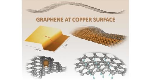
Atomistic-Scale Simulations on Graphene Bending Near a Copper Surface

1
Department of Mechanical Engineering, The Pennsylvania State University, University Park, PA 16802, USA
2
Department of Physics, The Pennsylvania State University, University Park, PA 16802, USA
3
Department of Chemistry, The Pennsylvania State University, University Park, PA 16802, USA
4
Department of Material Science and Engineering, The Pennsylvania State University, University Park, PA 16802, USA
5
Institute of Carbon Science and Technology, Shinshu University, 4-17-1 Wakasato, Nagano 380-8553, Japan
*
Author to whom correspondence should be addressed.
Catalysts 2021, 11(2), 208; https://doi.org/10.3390/catal11020208
Submission received: 6 January 2021 / Revised: 1 February 2021 / Accepted: 2 February 2021 / Published: 4 February 2021

Abstract

:
Molecular insights into graphene-catalyst surface interactions can provide useful information for the efficient design of copper current collectors with graphitic anode interfaces. As graphene bending can affect the local electron density, it should reflect its local reactivity as well. Using ReaxFF reactive molecular simulations, we have investigated the possible bending of graphene in vacuum and near copper surfaces. We describe the energy cost for graphene bending and the binding energy with hydrogen and copper with two different ReaxFF parameter sets, demonstrating the relevance of using the more recently developed ReaxFF parameter sets for graphene properties. Moreover, the draping angle at copper step edges obtained from our atomistic simulations is in good agreement with the draping angle determined from experimental measurements, thus validating the ReaxFF results.

Graphical Abstract

1. Introduction

Graphene, a two-dimensional sp-carbon-based material, has attracted a very high level of attention since its successful isolation in 2004 [1,2]. Graphene’s high electrical conductivity and its electrochemical properties like large reversible specific capacity, high rate capability, and cyclability makes it promising for use in energy storage applications such as lithium-ion batteries [3,4,5]. Though many studies have focused on its electronic properties, graphene also has exciting mechanical properties, such as an exceptionally high tensile strength (130 GPa) and Young’s modulus (1 TPa) [6,7]. Furthermore, novel electronic states can be realized in graphene by mechanical manipulation, granting it a versatility not possible in traditional materials [8]. In particular, studies have shown that rippled and wrinkled graphene have enhanced energy storage capabilities [7], as stretching of the C–C bonds due to corrugations changes the electronic structure and transport properties. Recently, Banerjee et al. [9] argued that the high-curvature regions of rippled graphene have a higher charge density than planar ones.
From a battery perspective, this graphene rippling is highly relevant for graphene-based anode materials, both for charge/discharge behavior and chemical interactions with the electrolyte, as well as for physical and chemical interactions with the current collector. The current collector is a vital component of a lithium-ion battery. During the battery discharge process, electrons from the anode are transported to the current collector and eventually to the external circuit. The stability of the current collector material and contact resistance of the collector/electrode interface significantly impact the electrochemical performance of lithium-ion batteries [10,11]. Striving to enhance battery performance, several studies have explored copper current collectors with graphitic anode interfaces [10,11,12,13]. A nanoscale investigation of graphene’s mechanical properties or its interactions with a catalyst surface requires the modeling of systems consisting of thousands of atoms, which makes these systems not practically accessible to quantum mechanical calculations. A nanometer-scale system can be modeled by using classical force field-based molecular dynamics (MD). For example, Pang et al. [14] presented atomistic MD data showing the graphene wrinkling along the graphene defects, such as Stone-Wales defects, as well as at the grain boundaries for the copper surface, and compared with the experimental results. The Pang et al. atomistic MD simulations were performed using a combination of the adoptive intermolecular reactive empirical bond order (AIREBO) potential to describe the carbon-carbon interactions, embedded atom method (EAM) potential to describe Cu-Cu atoms interactions, and Lennard-Jones 6–12 potential to describe only nonbonded copper-carbon interactions.
The ReaxFF method has been extensively applied in battery applications, especially in the areas of anode/electrolyte interfaces [15], electrolytes [16,17,18], and cathode/electrolyte interfaces [19,20]. However, no ReaxFF study has been reported on the current collector/electrode interface. As an initial step toward developing a ReaxFF description for copper current collector/graphene interfaces, we evaluated our recently developed Cu-C force field, which includes the revised graphene parameters from Srinivasan et al. (2015) [21], in order to assess its potential to describe such interfaces. First, we explore the bending of a small graphene sample only due to thermal fluctuations, then assess how this graphene bending can be modified by placing the graphene in a confined space.
The interactions of flat and rippled graphene sheets with copper surfaces are also tested, as well as graphene bending at copper step edges, where our calculated draping angle is compared with experimental data. To the best of our knowledge, the presented draping angle calculations based on the atomistic MD have not been previously reported. Finally, as the ReaxFF method is suitable for modeling heteroatomic systems, the binding energies for hydrogen and copper atoms to graphene surfaces with various geometries are calculated. Results indicate that the ReaxFF Cu-C force field is capable of reproducing graphene’s mechanical properties and provides useful information on its interactions with a metal surface, which validates the future use of ReaxFF for current collector interfaces in batteries.
The present study is focused solely on the physical and chemical response of graphene. The electronic response cannot be accurately obtained, as ReaxFF is not suitably trained for accurate charge distribution. The eReaxFF method [22], on the other hand, is an extension of the standard ReaxFF approach with an explicit electronic degree of freedom, and it is expected that eReaxFF may have the capability to compute more accurate charge distributions. The eReaxFF work reported by Islam et al. [22] demonstrates electron motion in several carbon-based systems, and this can be extended to graphitic systems in order to capture the electronic response of graphene.

2. Simulation Techniques and ReaxFF Force Field Descriptions

The quality of MD data depends significantly on the force field parameters used. Therefore, it is very important to wisely choose a suitable parameter set for our simulations. A number of atomistic force fields and their ability to reproduce the mechanical properties of carbon-based materials have been compared for this purpose. For example, Jensen et al. [23] presented data for diamond, amorphous carbon, carbon nanotubes, and graphene sheets obtained with use of different ReaxFF force fields and discussed these data in comparison to the literature, concluding which ReaxFF force field implementation was most suitable for the carbon allotropes modeling. ReaxFF is a reactive force field that can be used not only to determine the mechanical properties of graphene with a possible bond breaking, but also to provide a description of the nonbonded interaction between carbon and catalyst atoms. A more detailed description of the ReaxFF method can be found in the original ReaxFF papers [24,25]. The ReaxFF carbon parameters presented in the CHO-2016 force field [21] were developed to obtain better mechanical properties for graphene. The CHON-2019 force field [26] proposed for carbonization simulations incorporates the carbon parameters proposed by Srinivasan [21], and these Srinivasan parameters were also included in the recent extension of ReaxFF to copper interfaces with C/H/O species [27]. Unfortunately, the older C/H/O parameter sets—like the Chenoweth 2008 C/H/O combustion force field [25]—are still used in ReaxFF simulations on graphitic materials, although they were not trained for this. To indicate the significant difference between the Srinivasan 2015 carbon parameters [21] and the older ReaxFF parameter sets [25], we performed some of the key simulations presented here with both sets of parameters.
For all presented ReaxFF simulations, a time step of 0.1 fs and periodic boundary conditions were applied. We used the Berendsen [28] thermostat with a temperature coupling constant of 100 fs for all NVT simulations, where the number of atoms (N), volume (V), and temperature (T) are held constant. In the case of the NPT simulations, the Berendsen barostat was applied to maintain the system at zero pressure with a pressure coupling constant of 100 ps. All presented simulations were performed with the ADF simulation software [29], and simulation snapshots were generated with use of VMD (Visual Molecular Dynamics) [30] then Open Visualization Tool (OVITO) [31].

2.1. Bending in a Graphene Sheet

To assess the bending of a graphene sheet in the absence of a catalytic surface, just due to the thermal fluctuations and confined space, a small graphene sheet 8.3 × 5.8 nm (approximately 2000 carbon atoms) is considered, see Figure 1a. The graphene sheet is first energy-minimized and then NPT simulations are performed at 5 K in a periodic simulation box to further relax the graphene structure. During this stage of the simulation, we observe rippling of the free-standing planar graphene sheet, as seen in Figure 1a. This graphene sheet is then heated up to 1500 K and then cooled down (quench) to 77 K with a heating and cooling rate of 1.2 K/ps using an NPT ensemble. This annealing simulation causes the graphene fragment to decrease its number of ripples and settle in the shape of just a single ripple, as shown in Figure 1b. To quantify a possible strain distribution in the graphene after this simulated heat treatment, we calculated the average energy difference per atom for the last 100 configurations of the NPT simulations at 77 K. Figure 1c shows the relative strain energies as a colored heat map for the graphene configuration at 77 K. The energy values vary within a range of 0.005 kcal/mol, indicating a very small energy cost to generate the bend shown in Figure 1b.
These simulations show that it is possible to generate rippled graphene using only a thermal treatment; no interaction with a catalyst surface is necessary. To assess how this rippling effect depends on the length, as well as the thermal treatment, we consider graphene ribbons with lengths of 20, 40, and 80 nm (see Figure 1d–f).

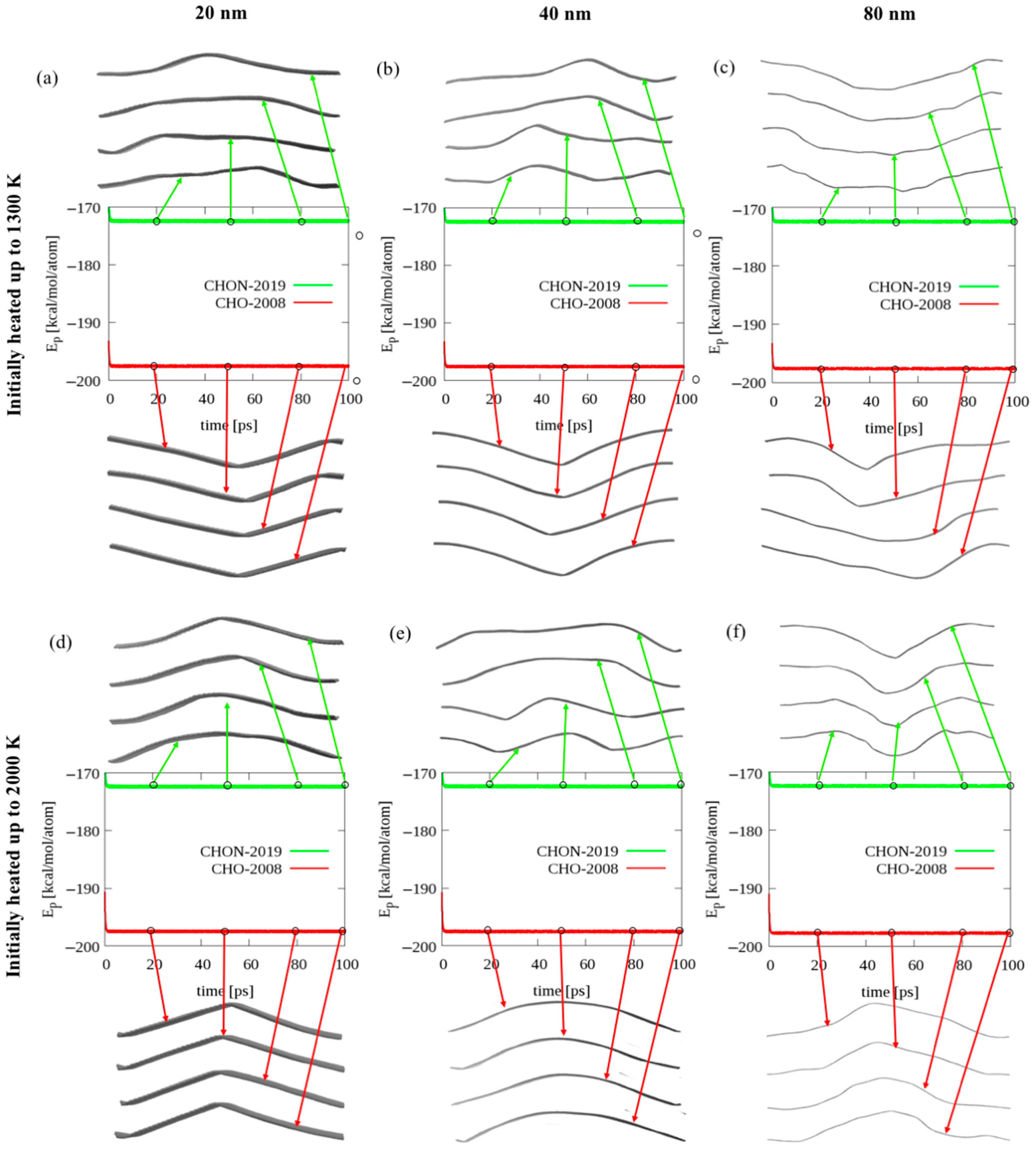
2.2. Bending of Long Graphene Ribbons

Ribbons with various lengths, see Figure 1d–f, were initially energy-minimized, relaxed at the NPT ensemble at the temperature of 300 K, and then heated up to either 1300 or 2000 K with a heating rate of 10 K/ps. All heated ribbons remained for an extra 100 ps in NPT simulations at the given temperature (1300 or 2000 K), and then the final configurations for all the ribbons were placed in a confined box at 77 K using NVT simulations. Figure 2 shows a comparison of the simulation snapshots for all considered graphene ribbons observed during the annealing simulations at 77 K and their corresponding potential energies. As we can see, all considered graphene ribbons adopt various bending configurations throughout the annealing simulations, without a significant change in their potential energy. We can also see that for the longer ribbons (40 and 80 nm), we often observe more than one ripple, whereas for the shortest ribbon, only one ripple can be observed. Moreover, based on a comparison of the values of the potential energies per atom, we see that using the CHON-2019 ReaxFF parameter set, we can reproduce the value of the potential energy per atom previously reported in the literature [32], while the CHO-2008 force field overestimates this value. This indicates that the CHON-2019 parameters, which include the 2015 Srinivasan et al. [21] carbon parameters, are significantly better at describing the graphene mechanical response than the earlier CHO-2008 carbon parameters.

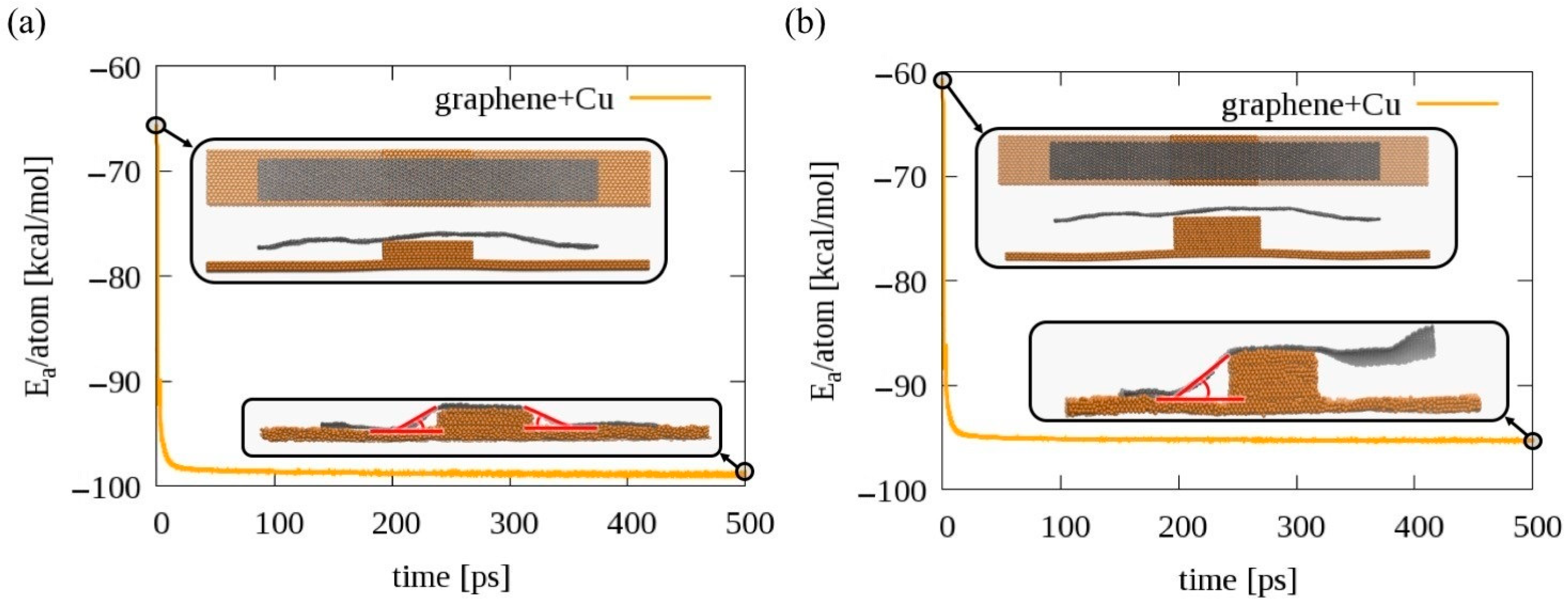
2.3. Graphene at Copper Surface

To test the possible effect of a copper surface on the graphene conformation, we use the Zhu 2020 ReaxFF parameters set [27], which includes the Srinivasan 2015 carbon parameters [21]. We placed the graphene sheet initially simulated using an NPT ensemble without a copper surface (Figure 1a) at the top of the copper surface (Figure 3a). Just placing this initially rippling graphene at the catalyst surface is sufficient to modify its configuration (Figure 3b). Unlike the graphene sheet converging to a half-wave conformation (Figure 1b), the graphene sheet placed at the Cu surface maintains its form due to the enhanced interaction between the copper surface atoms and carbon atoms located at the graphene bend region. The shape of the graphene sheet after annealing is then different compared to the free-standing graphene.

2.4. Determination of the Graphene Draping Angle

To test graphene bending in the presence of a copper surface, we built two copper surfaces with a step in the middle and placed a graphene ribbon on the top of the copper step. This is representative of step bunching seen in Cu foils underneath a graphene sample grown by CVD [33,34]. For one system, the step in the middle is smaller (only 6 Cu layers thick), whereas for the second system, the middle step is bigger (12 Cu layers). In Figure 4, the potential energies per atom for both systems are compared. As we can see, for the system with a smaller step, a 500 ps simulation at 300 K is enough for the graphene to bend sufficiently to interact with the copper surface and establish a draping angle on both sides of the step, see inset in Figure 4a. For the bigger step, 12 Cu layers thick, during this short NVT simulation at 300 K, we can observe that the graphene interacts with the Cu surface only on one side of the step; therefore, just one draping angle is established, see Figure 4b. By comparing the time evolution of the potential energies per atom for both these systems, we see that it is energetically favorable for the graphene ribbon to interact with the copper surface and create draping angles at the edges—we see a significant drop from the initial potential energies. Taking into account the last 10 configurations for both systems, the average draping angles, indicated in the Figure 4 insets in red for both systems, were estimated by using the image processing software ImageJ [35]. The average draping angle for the considered steps are 28 °   ±   4 ° for the small step and 30 °   ±   5 ° for the bigger one. Further exploration of the possible draping angle variation due to, e.g., the modified graphene geometry near the copper step edge, not only the height of the step, is another interesting research question worth separate study.
We check the theoretical prediction of graphene draping over a Cu step edge by measuring the draping angle directly, as pictured in Figure 5. Graphene is grown on a Cu substrate by chemical vapor deposition (CVD), and the sample is studied by a scanning tunneling microscope (STM) to find flat terraces separated by Cu step edges over which the graphene sheet drapes. The x and y piezoelectric scanners of the STM are calibrated using atomic-resolution images of the graphene sheet lying on the flat terraces. The z-piezos are calibrated by measuring the height of Bi2Se3 quintuple layers, each of which are 0.955 nm tall [36]. Extracting more than 150 independent linecut profiles like Figure 5b from topographic images, like Figure 5a, for many different step edges, we find the draping angle to be 32 °   ±   3 ° , in agreement with the theoretical calculations described in Figure 4, thus validating the ReaxFF graphene/copper interface description.

2.5. Reactivity of Rippled and Planar Graphene

In this section, we will discuss how the reactivity of graphene is affected by its curvature. To demonstrate this variation of reactivity, the hydrogenation energies and single copper atom binding energies are calculated for plane and rippled graphene.
Hydrogenation can occur either from one side or both sides of graphene, but both- sided hydrogenation is more stable [37,38]. We have calculated hydrogen binding energies, to describe the reaction kinetics, with graphene using the following equations:
(B.E.)H = [EHG − (EG + nEH)]/n   (binding energy with H atom reference)
(B.E.)H2 = [EHG − (EG + nEH2/2)]/n   (binding energy with H2 molecule reference)
where EHG, EG, EH, and EH2 are the energies of hydrogenated graphene, pristine graphene, H atom, and H2 molecule, respectively, and n is the number of H atoms that are hydrogenated. A negative value of the binding energy means the reaction is exothermic, which indicates the hydrogenation is stable. We have considered two ReaxFF force fields for the calculations—the CHON-2019 and CHO-2008 force fields—and compared our results with the density functional theory (DFT) calculations reported by Yi et al. [38]. Figure 6 shows the different configurations for single- and double-sided hydrogenation considered in the analysis, Table 1 and Table 2 summarize the single- and double-sided hydrogenation energies, respectively, and Table 3 compares the C–C bond lengths and C–C–C angles for the aforementioned configurations. In contrast to the CHO-2008 force field obtained results, the CHON-2019 force field predicts comparable hydrogenation energies with the DFT reference data reported by Yi et al. [38] when the single-sided hydrogenation is concerned. Similar to the DFT reference results, it is observed that the CHON-2019 force field predicts that the double-sided hydrogenation is more stable than the single-sided hydrogenation, and the 4Hc (chair-like; H atoms alternating on both sides of graphene) configuration is energetically more favorable than the 4Hb (boat-like; H atoms alternating in pairs) configuration. The CHO-2008 force field predicts reasonably well only for the double-sided hydrogenation, although it fails to correctly distinguish the difference in binding energies between the 4Hc and 4Hb configuration, and the predicted equilibrium values for the bonds and angles for these two configurations show a bigger discrepancy from the DFT data than the CHON-2019 predictions. Based on this comparison, we see that the CHON-2019 parameter set is, overall, more suitable to simulate the graphitic materials; however, further parametrization of the force field would be required to improve the double-sided hydrogenation energies.
Now, we show how the chair-like and boat-like hydrogenation compare for the effects of graphene curvature. We have taken small planar and rippled graphene sheets (112 C atoms) with periodic boundary conditions and created chair-like and boat-like configurations of hydrogenation (16 H atoms), as shown in Figure 7a,b,d,e. The hydrogenation energies obtained by using the CHON-2019 force field are summarized in Table 4. From the results, it can be observed that hydrogenation is at least 4 kcal/mol more stable for rippled graphene than plane graphene, which means hydrogenation is preferable at a rippled rather than planar site in graphene.
Similarly, we have analyzed the binding preference of a single copper atom on plane and rippled graphene (Figure 7c,f), and the binding energies are detailed in Table 5. The binding energy of copper with rippled graphene is 20 kcal/mol more energetically stable than plane graphene, which indicates that, similar to hydrogenation, copper prefers to bind with the rippled site of graphene rather than the planar site. As mentioned by Banerjee et al. [9], a rippled region of graphene has a higher charge density than a planar region, which may explain why hydrogen and copper binding are more favored at rippled rather than planar graphitic regions.

3. Conclusions

The purpose of this study was to evaluate the capability of the ReaxFF method to simulate the nanoscale effects of graphene bending and its interactions with catalyst surfaces such as copper. This investigation is an initial step toward developing a ReaxFF description for copper current collector/graphene interfaces. In our simulations, we used force fields based on the 2015 Srinivasan et al. [21] ReaxFF carbon parameters, as well as the older 2008 Chenoweth C/H/O parameters [25]. Our results indicate that the Srinivasan 2015 carbon parameters [21] are significantly more accurate for both the mechanical and the chemical response of graphene.
The presented data show that thermal fluctuation is sufficient for graphene, subjected to external stress, to ripple. Our results also indicate that lengths over 20 nm are sufficient to observe more than one ripple for the graphene. In addition, during short (100 ps) NVT simulations at 77 K, various graphene geometries were observed, while no significant change in the potential energy for all considered graphene was shown, indicating that ripple formation does not require a significant amount of energy.
The interactions of the flat and rippled graphene sheets with a copper surface were further tested, and we observed a noticeable change in the graphene geometry near the copper surface, associated with the binding of the graphene edges to the Cu-surface. Moreover, the bending of the graphene at the copper step edge was tested, and the graphene draping angle estimated form based on the ReaxFF simulations ( 28 °   ±   4 ° for the small step with 6 Cu layers and 30 °   ±   5 ° for the bigger step with 12 Cu layers) was compared with the experimental data ( 32 °   ±   3 ° ). The good agreement for the draping angle estimate from simulations and experiments suggests that at least at the atomistic level, no extra structure of the copper step is required to support graphene at the edge. Finally, the binding energies for the hydrogen and copper atoms to the graphene surface with various geometries are reported, indicating the capability of the reported force field to differentiate graphene reactivity based on its flat or rippled geometry.
Our results indicate that the ReaxFF Cu-C force field is capable of reproducing graphene’s mechanical properties and can provide useful information for its interactions with metal surfaces, indicating its further application to battery current collector/electrode interface simulations.

Supplementary Materials

The following are available online at https://www.mdpi.com/2073-4344/11/2/208/s1, Figure S1: Planar graphene sheet on Cu surface. Graphene sheet on Cu surface.

Author Contributions

M.K. MD simulation, data analysis and interpretation, writing, M.J.H. MD simulations, data analysis and interpretation, writing, A.L. MD simulations, data analysis and interpretation, W.Z. data analysis, R.B. measurements and data analysis and writing, E.W.H. editing, supervision, T.G.-N., M.T. sample preparation and data analysis, editing, A.C.T.v.D. data interpretation and editing, supervision. All authors have read and agreed to the published version of the manuscript.

Funding

M.K., M.J.H., W.Z., A.L. and A.C.T.v.D. acknowledge funding from DoE-NETL DE FE0026825 UCFER, the U.S. Army Research Laboratory through the Collaborative Research Alliance(CRA) for Multi-Scale Multidisciplinary Modeling of Electronic Materials (MSME) under Cooperative Agreement No. W911NF-12-2-0023, NASA Space TechnologyResearch Institute (STRI) for Ultra-Strong Composites by Computational Design (US-COMP), grant NNX17AJ32G and NSF DMR grants #1539916 and #1808900.

Data Availability Statement

Data available on request.

Conflicts of Interest

The authors declare no conflict of interest.

References

  1. Novoselov, K.S.; Geim, A.K.; Morozov, S.V.; Jiang, D.; Zhang, Y.; Dubonos, S.V.; Grigorieva, I.V.; Firsov, A.A. Electric Field Effect In Atomically Thin Carbon Films. Science 2004, 306, 666–669. [Google Scholar] [CrossRef] [PubMed] [Green Version]
  2. Novoselov, K.S.; Jiang, D.; Schedin, F.; Booth, T.J.; Khotkevich, V.V.; Morozov, S.V.; Geim, A.K. Two-dimensional Atomic Crystals. Proc. Natl. Acad. Sci. USA 2005, 102, 10451–10453. [Google Scholar] [CrossRef] [Green Version]
  3. Lian, P.; Zhu, X.; Liang, S.; Li, Z.; Yang, W.; Wang, H. Large Reversible Capacity of High Quality Graphene Sheets as an Anode Material for Lithium-ion Batteries. Electrochim. Acta 2010, 55, 3909–3914. [Google Scholar] [CrossRef]
  4. Wu, Z.-S.; Ren, W.; Xu, L.; Li, F.; Cheng, H.-M. Doped Graphene Sheets as Anode Materials with Superhigh Rate and Large Capacity for Lithium Ion Batteries. ACS Nano 2011, 5, 5463–5471. [Google Scholar] [CrossRef]
  5. Hassoun, J.; Bonaccorso, F.; Agostini, M.; Angelucci, M.; Betti, M.G.; Cingolani, R.; Gemmi, M.; Mariani, C.; Panero, S.; Pellegrini, V.; et al. An Advanced Lithium-Ion Battery Based on a Graphene Anode and a Lithium Iron Phosphate Cathode. Nano Lett. 2014, 14, 4901–4906. [Google Scholar] [CrossRef] [PubMed] [Green Version]
  6. Lee, C.; Wei, X.; Kysar, J.W.; Hone, J. Measurement of the Elastic Properties and Intrinsic Strength of Monolayer Graphene. Science 2008, 321, 385–388. [Google Scholar] [CrossRef] [PubMed]
  7. Deng, S.; Berry, V. Wrinkled, Rippled and Crumpled Graphene: An Overview of Formation Mechanism, Electronic Properties, and Applications. Mater. Today 2016, 19, 197–212. [Google Scholar] [CrossRef]
  8. Levy, N.; Burke, S.A.; Meaker, K.L.; Panlasigui, M.; Zettl, A.; Guinea, F.; Neto, A.H.C.; Crommie, M.F. Strain-Induced Pseudo-Magnetic Fields Greater Than 300 Tesla in Graphene Nanobubbles. Science 2010, 329, 544–547. [Google Scholar] [CrossRef] [Green Version]
  9. Banerjee, R.; Nguyen, V.-H.; Granzier-Nakajima, T.; Pabbi, L.; Lherbier, A.; Binion, A.R.; Charlier, J.-C.; Terrones, M.; Hudson, E.W. Strain Modulated Superlattices in Graphene. Nano Lett. 2020, 20, 3113–3121. [Google Scholar] [CrossRef]
  10. Dai, S.; Chen, J.; Ren, Y.; Liu, Z.; Chen, J.; Li, C.; Zhang, X.; Zhang, X.; Zeng, T. Electrochemical Corrosion Behavior of the Copper Current Collector in the Electrolyte of Lithium-ion Batteries. Int. J. Electrochem. Sci. 2017, 12, 10589–10598. [Google Scholar] [CrossRef]
  11. Kim, H.R.; Choi, W.M. Graphene Modified Copper Current Collector for Enhanced Electrochemical Performance of Li-ion Battery. Scr. Mater. 2018, 146, 100–104. [Google Scholar] [CrossRef]
  12. Lahiri, I.; Oh, S.-W.; Hwang, J.Y.; Cho, S.; Sun, Y.-K.; Banerjee, R.; Choi, W. High Capacity and Excellent Stability of Lithium Ion Battery Anode Using Interface-Controlled Binder-Free Multiwall Carbon Nanotubes Grown on Copper. ACS Nano 2010, 4, 3440–3446. [Google Scholar] [CrossRef]
  13. Liu, X.; Wang, D.; Zhang, B.; Luan, C.; Qin, T.; Zhang, W.; Wang, D.; Shi, X.; Deng, T.; Zheng, W.T. Vertical Graphene Nanowalls Coating of Copper Current Collector for Enhancing Rate Performance of Graphite Anode of Li Ion Battery: The Merit of Optimized Interface Architecture. Electrochim. Acta 2018, 268, 234–240. [Google Scholar] [CrossRef]
  14. Pang, Z.; Deng, B.; Liu, Z.; Peng, H.; Wei, Y. Defects Guided Wrinkling in Graphene on Copper Substrate. Carbon 2019, 143, 736–742. [Google Scholar] [CrossRef] [Green Version]
  15. Islam, M.; Bryantsev, V.S.; van Duin, A.C.T. ReaxFF Reactive Force Field Simulations on the Influence of Teflon on Electrolyte Decomposition during Li/SWCNT Anode Discharge in Lithium-Sulfur Batteries. J. Electrochem. Soc. 2014, 161, E3009–E3014. [Google Scholar] [CrossRef] [Green Version]
  16. Bedrov, D.; Smith, G.D.; van Duin, A.C.T. Reactions of Singly-Reduced Ethylene Carbonate in Lithium Battery Electrolytes: A Molecular Dynamics Simulation Study Using the ReaxFF. J. Phys. Chem. A 2011, 116, 2978–2985. [Google Scholar] [CrossRef]
  17. Ong, M.T.; Verners, O.; Draeger, E.W.; van Duin, A.C.T.; Lordi, V.; Pask, J.E. Lithium Ion Solvation and Diffusion in Bulk Organic Electrolytes from First-Principles and Classical Reactive Molecular Dynamics. J. Phys. Chem. B 2015, 119, 1535–1545. [Google Scholar] [CrossRef] [Green Version]
  18. Hossain, J.; Pawar, G.; Liaw, B.; Gering, K.L.; Dufek, E.J.; van Duin, A.C.T. Lithium-electrolyte Solvation and Reaction in the Electrolyte of a Lithium Ion Battery: A ReaxFF Reactive Force Field Study. J. Chem. Phys. 2020, 152, 184301. [Google Scholar] [CrossRef] [PubMed]
  19. Van Duislamn, A.C.; Ostadhossein, A.; Borodin, O.; Yeates, A.T.; Tipton, W.W.; Hennig, R.G.; Kumar, N.; Van Duin, A.C. ReaxFF Molecular Dynamics Simulations on Lithiated Sulfur Cathode Materials. Phys. Chem. Chem. Phys. 2014, 17, 3383–3393. [Google Scholar] [CrossRef]
  20. Reddivari, S.; Lastoskie, C.; Wu, R.; Zhang, J. Chemical Composition and Formation Mechanisms in the Cathode-electrolyte Interface Layer of Lithium Manganese Oxide Batteries from Reactive Force Field (ReaxFF) Based Molecular Dynamics. Front. Energy 2017, 11, 365–373. [Google Scholar] [CrossRef]
  21. Srinivasan, S.G.; van Duin, A.C.T.; Ganesh, P. Development of a ReaxFF Potential for Carbon Condensed Phases and Its Application to the Thermal Fragmentation of a Large Fullerene. J. Phys. Chem. A 2015, 119, 571–580. [Google Scholar] [CrossRef] [PubMed]
  22. Islam, M.; Kolesov, G.; Verstraelen, T.; Kaxiras, E.; van Duin, A.C.T. eReaxFF: A Pseudoclassical Treatment of Explicit Electrons within Reactive Force Field Simulations. J. Chem. Theory Comput. 2016, 12, 3463–3472. [Google Scholar] [CrossRef] [PubMed]
  23. Jensen, B.D.; Wise, K.E.; Odegard, G.M. Simulation of the Elastic and Ultimate Tensile Properties of Diamond, Graphene, Carbon Nanotubes, and Amorphous Carbon Using a Revised ReaxFF Parametrization. J. Phys. Chem. A 2015, 119, 9710–9721. [Google Scholar] [CrossRef] [PubMed]
  24. van Duin, A.C.T.; Dasgupta, S.; Lorant, F.; Goddard, W.A. ReaxFF:  A Reactive Force Field for Hydrocarbons. J. Phys. Chem. A 2001, 105, 9396–9409. [Google Scholar] [CrossRef] [Green Version]
  25. Chenoweth, K.; van Duin, A.C.T.; Goddard, W.A. ReaxFF Reactive Force Field for Molecular Dynamics Simulations of Hydrocarbon Oxidation. J. Phys. Chem. A 2008, 112, 1040–1053. [Google Scholar] [CrossRef] [Green Version]
  26. Kowalik, M.; Ashraf, C.; Damirchi, B.; Akbarian, D.; Rajabpour, S.; van Duin, A.C.T. Atomistic Scale Analysis of the Carbonization Process for C/H/O/N-Based Polymers with the ReaxFF Reactive Force Field. J. Phys. Chem. B 2019, 123, 5357–5367. [Google Scholar] [CrossRef] [PubMed]
  27. Zhu, W.; Gong, H.; Han, Y.; Zhang, M.; van Duin, A.C.T. Development of a Reactive Force Field for Simulations on the Catalytic Conversion of C/H/O Molecules on Cu-Metal and Cu-Oxide Surfaces and Application to Cu/CuO-Based Chemical Looping. J. Phys. Chem. C 2020, 124, 12512–12520. [Google Scholar] [CrossRef]
  28. Berendsen, H.J.C.; Postma, J.P.M.; van Gunsteren, W.F.; DiNola, A.; Haak, J.R. Molecular Dynamics with Coupling to an External Bath. J. Chem. Phys. 1984, 81, 3684–3690. [Google Scholar] [CrossRef] [Green Version]
  29. Chemistry, S.T. ADF Modeling Suite; Vrije Universiteit: Amsterdam, The Netherlands, 2017. [Google Scholar]
  30. Humphrey, W.; Dalke, A.; Schulten, K. VMD: Visual Molecular Dynamics. J. Mol. Graph. 1996, 14, 33–38. [Google Scholar] [CrossRef]
  31. Stukowski, A. Visualization and Analysis of Atomistic Simulation Data with OVITO–the Open Visualization Tool. Model. Simul. Mater. Sci. Eng. 2009, 18, 015012. [Google Scholar] [CrossRef]
  32. Liu, X.; Wang, F.C.; Wu, H. Anomalous Twisting Strength of Tilt Grain Boundaries in Armchair Graphene Nanoribbons. Phys. Chem. Chem. Phys. 2015, 17, 31911–31916. [Google Scholar] [CrossRef]
  33. Kang, J.H.; Moon, J.; Kim, D.J.; Kim, Y.; Jo, I.; Jeon, C.; Lee, J.; Hong, B.H. Strain Relaxation of Graphene Layers by Cu Surface Roughening. Nano Lett. 2016, 16, 5993–5998. [Google Scholar] [CrossRef]
  34. Yi, D.; Luo, D.; Wang, Z.-J.; Dong, J.; Zhang, X.; Willinger, M.; Ruoff, R.S.; Ding, F. What Drives Metal-surface Step Bunching in Graphene Chemical Vapor Deposition? Phys. Rev. Lett. 2018, 120, 246101. [Google Scholar] [CrossRef] [PubMed] [Green Version]
  35. Schneider, C.A.; Rasband, W.S.; Eliceiri, K.W. NIH Image to ImageJ: 25 years of Image Analysis. Nat. Methods 2012, 9, 671–675. [Google Scholar] [CrossRef]
  36. Zhang, J.; Peng, Z.; Soni, A.; Zhao, Y.; Xiong, Y.; Peng, B.; Wang, J.; Dresselhaus, M.S.; Xiong, Q. Raman Spectroscopy of Few-Quintuple Layer Topological Insulator Bi2Se3Nanoplatelets. Nano Lett. 2011, 11, 2407–2414. [Google Scholar] [CrossRef]
  37. Sofo, J.O.; Chaudhari, A.S.; Barber, G.D. Graphane: A Two-dimensional Hydrocarbon. Phys. Rev. B 2007, 75, 153401. [Google Scholar] [CrossRef] [Green Version]
  38. Yi, D.; Yang, L.; Xie, S.; Saxena, A.B. Stability of Hydrogenated Graphene: A First-principles Study. RSC Adv. 2015, 5, 20617–20622. [Google Scholar] [CrossRef]
Figure 1. The free-standing graphene sheets. (a) Rippling of a free-standing graphene sheet obtained from the NPT simulations at 5 K with use of the periodic boundary conditions. (b) Final geometry of the graphene sheet after heating up to 1500 K, cooling to 77 K (with a rate 1.2 K/ps), and then annealing at 77 K for 100 ps. (c) Top view of the graphene sheet, color-coded based on average strain energy difference calculated for the last 100 configurations of its annealing at 77 K. (df) Initial geometries for the graphene ribbons with 3 different lengths: 20, 40, and 80 nm.
Catalysts 11 00208 g001
Figure 2. The graphene ribbon geometries and their corresponding potential energies. Comparison of simulation snapScheme 20. 40, and 80 nm) after initial heating to 1300 K (ac), or 2000 K (df), followed by annealing at 77 K for 100 ps using a number of atoms, volume, and temperature (NVT) ensemble. The middle panel shows a comparison of the time evolution of the potential energy for the corresponding graphene ribbons using the CHON-2019 (green) and CHO-2008 (red) ReaxFF parameter sets.
Catalysts 11 00208 g002
Figure 3. Graphene sheet on Cu surface (see Supplementary Materials). (a) Rippled graphene sheet on Cu surface before simulated annealing. (b) Rippled graphene sheet on Cu surface after simulated annealing at 77 K. Orange/grey spheres indicate Cu/C atoms, respectively.
Catalysts 11 00208 g003
Figure 4. The graphene ribbon at the copper steps. Time evolution of potential energy for a graphene ribbon of length 40 nm placed at the top of copper surfaces with (a) 6 Cu layer and (b) 12 Cu layer step edges. Insets at the top of both graphs show the initial structure for the ribbon, top and side view. Insets at the bottom of both graphs show the final configurations for the considered systems. Orange/grey spheres indicate Cu/C atoms, respectively.
Catalysts 11 00208 g004
Figure 5. Experimental measurements of the draping angle. From STM images (a), we extract linecut profiles (b) to measure the draping distance (R) for step edges of different heights (H). (c) Plotting step height vs. draping distance for many step edges, we find that the data collapse on a straight line, implying that the draping angle is indeed conserved. The draping angle, determined from the slope of the linear fit, 32 °   ±   3 ° , is consistent with our ReaxFF prediction.
Catalysts 11 00208 g005
Figure 6. Different configurations of single-sided (1H, 2Hm, 2Hp, and 3Hc) and double-sided (4Hc and 4Hb) hydrogenated graphene. The cyan/grey spheres indicate H/C atoms, respectively.
Catalysts 11 00208 g006
Figure 7. Planar and rippled graphene sheets for hydrogenation and copper binding. (a) Chair-like hydrogenation on plane graphene, (b) boat-like hydrogenation on plane graphene, (c) Cu binding on plane graphene, (d) chair-like hydrogenation on rippled graphene, (e) boat-like hydrogenation on rippled graphene, and (f) Cu binding on rippled graphene. Cyan/orange/grey spheres indicate H/Cu/C atoms, respectively.
Catalysts 11 00208 g007
Table 1. Single-sided hydrogenation energies for different configurations.
Binding Energy with H Atom ReferenceCHO-2008
(kcal/mol)
CHO-2019
(kcal/mol)
DFT Reference [38]
(kcal/mol)
1H−80.82−27.63−25.37
2Hm−62.55−21.75−21.91
2Hp−64.60−35.84−46.12
3Hc−49.67−16.96−20.75
Binding Energy with H2 Molecule ReferenceCHO-2008
(kcal/mol)
CHO-2019
(kcal/mol)
DFT Reference [38]
(kcal/mol)
1H−26.0424.8927.67
2Hm−7.7730.7729.98
2Hp−9.8216.695.77
3Hc5.1235.5731.13
Table 2. Double-sided hydrogenation energies for different configurations.
Binding Energy with H Atom ReferenceCHO-2008
(kcal/mol)
CHO-2019
(kcal/mol)
DFT Reference [38]
(kcal/mol)
4Hc−69.39−57.17−63.42
4Hb−69.35−54.11−61.11
Binding energy with H2 molecule referenceCHO-2008
(kcal/mol)
CHO-2019
(kcal/mol)
DFT Reference [38]
(kcal/mol)
4Hc−14.61−4.64−11.53
4Hb−14.56−1.58−9.22
Table 3. C–C bonds and C–C–C angles for different configurations of double-sided hydrogenation.
4HcCHO-2008CHO-2019DFT Reference [38]
C–C bond1.557 Å1.529 Å1.539 Å
C–C–C angle104.6°107.2°111.4°
4HbCHO-2008CHO-2019DFT Reference [38]
C–C bond1.570 Å1.539 Å1.539 Å
C–C–C angle108.2°109.9°111.8°
Table 4. Hydrogenation energies for chair- and boat-like configurations in plane and rippled graphene.
Binding Energy with H Atom ReferencePlane
(kcal/mol)
Rippled
(kcal/mol)
chair-like−52.38−57.12
boat-like−50.04−54.59
Binding Energy with H2 Molecule ReferencePlane
(kcal/mol)
Ripple
(kcal/mol)
chair-like0.15−4.60
boat-like2.49−2.06
Table 5. Copper binding energies for plane and rippled graphene.
Binding Energy with Cu Atom ReferenceCu-C Force Field
(kcal/mol)
plane graphene−37.32
rippled graphene−57.53
Publisher’s Note: MDPI stays neutral with regard to jurisdictional claims in published maps and institutional affiliations.

