Abstract
Vanadium redox flow battery (VRFB) is one of the most promising technologies for grid-scale energy storage applications because of its numerous attractive features. In this study, metal-organic frameworks (MOF)-derived catalysts (MDC) are fabricated using carbonization techniques at different sintering temperatures. Zirconium-based MOF-derived catalyst annealed at 900 °C exhibits the best electrochemical activity toward VO2+/VO2+ redox couple among all samples. Furthermore, the charge-discharge test confirms that the energy efficiency (EE) of the VRFB assembled with MOF-derived catalyst modified graphite felt (MDC-GF-900) is 3.9% more efficient than the VRFB using the pristine graphite felt at 100 mA cm−2. Moreover, MDC-GF-900 reveals 31% and 107% higher capacity than the pristine GF at 80 and 100 mA cm−2, respectively. The excellent performance of MDC-GF-900 results from the existence of oxygen-containing groups active sites, graphite structure with high conductivity embedded with zirconium oxide, and high specific surface area, which are critical points for promoting the vanadium redox reactions. Because of these advantages, MDC-GF-900 also possesses superior stability performance, which shows no decline of EE even after 100 cycles at 100 mA cm−2.
1. Introduction
Because of rapid industrial development, global energy demand is rising quickly. The excessive use of fossil fuels causes environmental pollution and immediate consumption of these non-renewable resources. Sustainable energy sources such as solar and wind have been explored in recent years to alleviate these problems. However, such sustainable energy sources are intermittent and random, inducing low-quality output electricity and influencing power grid stability. Therefore, developing efficient energy storage systems (ESSs) is vital to integrate sustainable energy sources into the electrical grids supply [1]. Among various ESSs, a vanadium redox flow battery (VRFB) is a good choice since it possesses plenty of advantages, such as large-scale design flexibility, long lifetime, and low maintenance costs [2]. Moreover, it can be charged and discharged by transforming the oxidation state of vanadium ions both on the positive side (VO2+/VO2+) and the negative side (V2+/V3+). As reactive molecules on both sides are vanadium ions, the crossover problems between two half-cells can be avoided.
The electrolyte of VRFB contains sulfuric acid. Thus, typical electrode materials in VRFB need to be highly anti-corrosive and highly stable, such as graphite felt (GF), carbon cloth, and carbon felt. Nevertheless, these carbon fiber-based materials have hydrophobic features, poor reversibility in kinetics, and few active sites, resulting in poor performance of VRFB [3,4]. Therefore, different modification methods of electrodes, including thermal treatment, chemical treatment, adding catalysts, have been developed recently. Among them, applying catalysts to modify the electrodes is one of the valuable methods. These catalysts can be roughly divided into metallic, metal oxides, and non-metallic materials. Metallic catalysts like In [5], Ir [6], and Pt [7] have been utilized owing to their high electrochemical activity, outstanding conductivity, and anti-corrosion property toward acidic electrolytes. However, these noble metals have lower elemental abundance and higher costs. To diminish the costs, cheap metal oxides such as Nb2O5 [8], Ta2O5 [9], W18O49 [10], and CeO2 [11] have been studied and exhibited good electrocatalytic activity. However, since the transition metal cations present several oxidative states, they make oxidation and reduction reactions carry on poor electronic conductivity and hinder the charge transfer efficiency from the catalysts to electrodes. To solve this problem, some carbonaceous materials with high conductivity, such as carbon nanotubes (CNTs) [12,13], graphene [14,15], and carbon nanorods [16], are used to combine with metal oxides catalysts to further improving the performance of VRFB. These carbonaceous materials can be treated as support of other catalysts and can become superior catalysts by themselves. Generally, they positively affect carbon electrodes due to their high specific surface area, good conductivity, and abundant active sites, which have proved high contents of oxygen-functional groups [17].
Besides the different catalysts aforementioned, metal-organic frameworks (MOFs) have attracted lots of attention in catalysts because of their tunable structure, high porosity, and ease of functionalization [18,19]. In addition, MOFs possess a stable structure that is composed of metal-based nodes and organic linkers. However, most MOFs lack good conductivity, so they are seldom used in the electrochemical field. To enhance their conductivity, several methods have been applied, such as building a smooth electron transport route within MOFs [20,21], assembling conductive materials with MOFs [22,23,24], carbonizing MOFs to become porous carbon and metal-containing compounds [25,26]. Among them, the carbonization method is much easier to be conducted and has been tried by few research groups of VRFBs. For example, in 2017, Ge et al. synthesized cobalt phosphide (CoP) nanoparticles from zeolitic imidazole framework (ZIF)-67 by sintering in the air for 5 h at 550 °C, and followed by phosphatization. The as-synthesized CoP catalyst was deposited onto the surface of GF and showed good electrocatalytic activity towards VO2+/VO2+ [27]. In 2018, Noh et al. utilized ZIF-8 as seeds to synthesize ZIF-8@ZIF-67 with core-shell structure and carbonization at 900 °C in an argon atmosphere to produce mesoporous N-doped carbon with carbon nanotubes (m-NC@NCNT). Because of its high specific surface area, superior conductivity, and plenty of active sites provided by nitrogen-doping, the single-cell assembled with m-NC@NCNT modified electrodes exhibited 84.2% of energy efficiency (EE) at 120 mA cm−2, which was much better than that of the control [28]. Recently, Li et al. proposed a new technique to control carbon electrodes’ microstructure and functional doping by carbonizing cobalt-based metal-organic framework (Co-MOF) precursors decorated on GF. The obtained electrode (PCP-800) revealed an excellent VRFB performance [29].
This paper has successfully fabricated ZrO2 from zirconium-based MOF through a carbonization route at different annealing temperatures and employed it as a catalyst for VRFB (see the supporting information, Scheme S2). The as-synthesized MOF-derived ZrO2-modified GF electrode exhibits better electrochemical performance towards VRFB due to the higher surface area and porosity of carbon, which are critical points for promoting the vanadium redox reactions.
2. Results and Discussion
2.1. Morphological and Structural Characterization
As shown from the X-ray diffraction (XRD) patterns of Figure 1a, Zr-MOF has strong diffraction peaks at 7.5° and 8.7°, confirming that the successful fabrication of a highly crystalline Zr-MOF structure [30]. However, when carbonization was performed at 500 °C, the original strong diffraction peaks disappear. A low and broad amorphous peak appears at around 30°, indicating that a new crystalline structure is gradually being produced. When sintering at 700 °C, there are four prominent diffraction peaks at 30.2°, 35.3°, 50.2°, and 60.2°, which correspond to the characteristic peaks of tetragonal ZrO2 (Database: PDF 79-1769). The strongest peak with a sharp shape is formed at 30.2° diffraction from the (101) crystal plane as sintering to 900 °C, signifying that its crystallinity increases with increasing sintering temperature. This result reveals that the main structure of metal-organic frameworks derived from the catalysts at 900 °C (MDC-900) is tetragonal ZrO2.
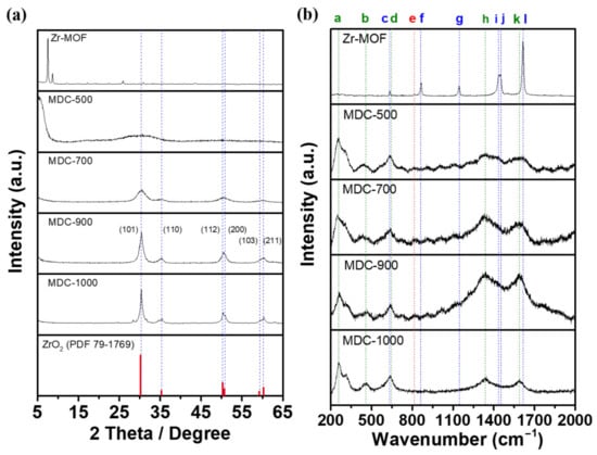
Figure 1.
(a) XRD patterns and (b) Raman spectra of Zr-MOF, MDC-500, MDC-700, MDC-900, and MDC-1000.
Raman spectroscopy uses the Raman scattered light caused by molecular vibration to study the bonding status of materials. It can be seen from Figure 1b that Zr-MOF has Raman scattering peaks at vibration frequencies 633(c), 860(f), 1142(g), 1437(i), 1450(j), and 1615(l) cm−1, which represent “C–C–C benzene ring in-plane bending vibration”, “O–H bending vibration and C–C symmetric ring breathing”, “C–C symmetric ring breathing”, “C–C benzene ring and carboxyl group stretching vibration”, “O–C–O carboxyl group symmetric stretching vibration”, and “C–C benzene ring stretching vibration”, respectively [31]. These signals based on benzene rings prove the presence of terephthalic acid linker molecules in Zr-MOF. After sintering at 500 °C to 1000 °C, the Raman scattering peaks have substantially changed, and the peaks located at 258(a), 466(b), and 636(c) cm−1 can be ascribed to the bending and stretching vibration of tetragonal ZrO2 [32,33]. Moreover, the peaks which represent disordered carbon and graphitized carbon appear at 1339(h) cm−1 (D-band) and 1588(k) cm−1 (G-band) [34]. The reason for this situation might be the collapse of the benzene ring structure in the Zr-MOF, and the carbon atoms are rearranged to form the graphitized structure. Compared with the D-band and G-band intensity (ID/IG) of MDC-500, MDC-700, MDC-900, and MDC-1000, MDC-900 has the lowest ID/IG value of 1.05, which shows a higher percentage of graphitic structure with better conductivity. When the sample was treated at a higher sintering temperature (1000 °C), the ID/IG ratio of MDC-1000 sample (ID/IG = 1.14) is higher than that of MDC-900 (ID/IG = 1.05) owing to some breakage of graphitized carbon and the formation of disordered carbon structure at relatively higher temperature [35]. On the other hand, the zirconium and oxygen atoms in the metal-based nodes directly crystallize to form tetragonal ZrO2. It meant that crystallites of tetragonal ZrO2 possibly integrated with the carbon structure, and the conductivity might be enhanced compared with pure tetragonal ZrO2. It is worth mentioning that the scattering peak of 814(e) cm−1 represents “O–H bending vibration” that exists both before and after sintering, confirming that the presence of hydroxyl groups which can serve as active sites on MDC-900.
The SEM image with high magnification (100,000 times) was used to see the morphology difference before and after Zr-MOF’s carbonization was shown in Figure 2. Zr-MOF exhibits polyhedral particles with rounded corners, in which the particle size is about 100 nm with a smooth surface. On the contrary, MDC-900 shows that the polyhedron morphology has been destroyed, and the boundary between the particles has become blurred. Moreover, in the case of MDC-900, the surface is no longer smooth, and some smaller particles are attached to it. Compared with the previous XRD results, it can be found that the tiny particles appearing on the surface of MDC-900 may be tetragonal ZrO2 grains produced by high-temperature sintering.
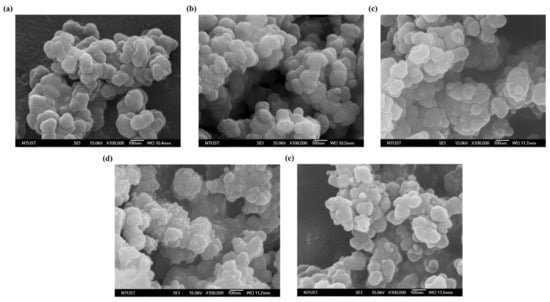
Figure 2.
SEM images of (a) Zr-MOF, (b) MDC-500, (c) MDC-700, (d) MDC-900, and (e) MDC-1000.
TEM images were utilized to further understand the difference in the particles of Zr-MOF before and after carbonization, as shown in Figure 3. From the Zr-MOF image (Figure 3a), it can be found that the particle size is about 100 nm, which is consistent with the SEM image and without noticeable lattice fringe that implies that the amorphous structure of Zr-MOF. After carbonization at 900 °C, there are several tiny grains in MDC-900 particles, and the original MOF particle boundary almost disappears, which corresponds with the SEM image (Figure 3b). To realize the composition of the new crystallites inside the particles, it can be found in Figure 3c that the diameter of small crystallites produced by sintering is about 7 nm, and the lattice d-spacing is obtained to be 0.296 nm, corresponding to the (101) crystal plane of the tetragonal ZrO2 grains. It is worth mentioning that tetragonal ZrO2 grains are integrated with amorphous materials, which might be carbon in the molecules of MDC-900. High-angle annular dark-field-scanning TEM (HAADF-STEM) and the corresponding elemental mapping results (Figure 3d–g) verified the excellent distribution of zirconium, carbon, and oxygen in MDC-900 sample area; these results are consistent with observations from Raman spectra and HRTEM in which ZrO2 grains were embedded with a carbon structure.
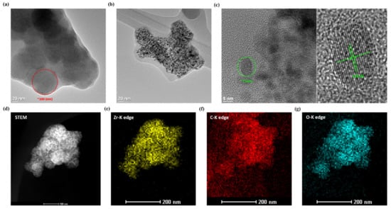
Figure 3.
TEM images of (a) Zr-MOF and (b) MDC-900; (c) HRTEM images with enlarging one which is labeled d-spacing of MDC-900; the (d) HAADF-STEM image of MDC-900 and elemental mapping of (e) Zr-K edge, (f) C-K edge, and (g) O-K edge.
MOFs are highly attracted to numerous applications because of their porous structures and extremely high surface areas. To determine the specific surface area of MOF–derived catalysts, Brunauer-Emmett-Teller (BET) nitrogen adsorption-desorption analysis was conducted. It can be found that the adsorption and desorption curves of Zr-MOF present a Langmuir isotherm (Figure 4), indicating that it is a microporous structure with a specific surface area of 1145 m2 g−1. The specific surface area of Zr-MOF is remarkably reduced to 130 m2 g−1 after 900 °C of carbonization, implying that the porous structure of this MOF might be destroyed at high temperature, which is consistent with the results of Raman spectroscopy. However, the specific surface area of MDC-900 °C is much higher than that of commercial ZrO2 (32 m2 g−1), which might be beneficial to improve catalytic activity towards vanadium redox reactions.
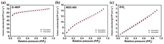
Figure 4.
BET nitrogen adsorption and desorption curves of (a) Zr-MOF, (b) MDC-900, and (c) ZrO2.
X-ray photoelectron spectroscopy (XPS) was utilized to analyze the elemental composition and chemical bonding on the surface of materials. To find the possible reasons why MDC-900 possesses superior electrochemical activity, the survey and narrow scan spectra of XPS were performed in Figure 5. As observed in Figure 5a, the zirconium, carbon, oxygen, and gold peaks were identified. Except for gold which was used to enhance the conductivity of samples during XPS characterization, other elements in the survey correspond with the results of TEM elemental mapping. For the narrow scan spectrum of C 1s, the bonds of C–C, Zr–O–C, and C=O appeared at 284.5, 286.3, and 288.5 eV, respectively (Figure 5b) [36]. The peak of C–C bond showed larger full width at half maximum (FWHM), and the reason could be the dangling bonds with different orientations distributed on the edge of graphitic structure [37]. The signal of C=O bond indicated that some oxygen functional groups grafted on the carbon structure of MDC-900, which might be served as the active sites. A new Zr–O–C bond confirms that the ZrO2 particles are attached strongly to the carbon material, significantly facilitating the vanadium redox couple reaction [15]. In the O 1s spectrum, the lattice O2− could be found because of the formation of tetragonal ZrO2 crystallites after sintering at 900 °C. At the binding energy of 531.7 and 533.1 eV, the existence of HO-Zr and C–OH bonds displayed that the hydroxyl groups were proved to be more electrochemically active sites for vanadium redox reactions (Figure 5c) [36,38]. For Zr 3d spectrum, two strong peaks of Zr 3d5/2 and Zr 3d3/2 were demonstrated at 182.0 and 184.4 eV, respectively, which resulted from the crystallites structure of tetragonal ZrO2 (Figure 5d) [36].
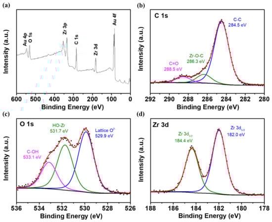
Figure 5.
XPS spectra showing (a) the wide scan and the narrow scans of (b) C 1s, (c) O 1s, and (d) Zr 3d for MDC-900.
2.2. Electrochemical Characterization
For realizing the effect of different sintering temperatures on the electrocatalytic activity of Zr-MOF, a rotating disk electrode (RDE) was applied in the half-cell tests on both the positive and negative electrodes separately. On the positive side (Figure 6a), it can be observed that the potential separation between oxidation and reduction peaks for MDC-900 is 222 mV, which is smaller than other treatments except for MDC-1000. However, MDC-1000 has the lowest peak potential separation, but its oxidation peak current density is only 31.258 mA cm−2, lower than 39.82 mA cm−2 of MDC-900. Thus, it indicates that MDC-900 has comprehensively high activity. Notably, the peak separation of Zr-MOF without carbonization is slightly smaller than that of catalyst-free RDE. Still, the peak current density is low, which represents its few active sites.
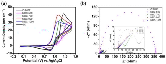
Figure 6.
Cycle voltammetry (CV) curves of (a) positive electrode obtained at the scan rate of 10 mV s−1, (b) EIS curves of various samples obtained at a potential of polarization 1.0 V. The electrolyte was composed of 1.6 M VOSO4 plus 4.6 M H2SO4.
On the other hand, the peak separation of MDC-500 obtained after sintering at 500 °C increases significantly, and the disappearance of the reduction peak indicates insufficient catalytic activity. When the sintering temperature rises to 700 °C, the catalytic activity improves, and the optimum electrocatalytic activity is reached after carbonization at 900 °C. The essential factors for the activity improvement of MDC-900 sample might be the formation of tetragonal ZrO2 and graphite structure based on the XRD and Raman spectroscopy results, providing more active sites and better conductivity, respectively. In the previous study, Zhou et al. proposed that the hydroxyl groups on ZrO2 can be served as active sites to assist the electrochemical reactions of vanadium ions [39]. In our case, as ZrO2 is integrated with a graphite structure that has better conductivity, the synergistic effect between them might further improve the electron transfer from active sites to the electrode surface. However, if the sintering temperature further increases to 1000 °C, the peak current density decreased compared with that of 900 °C, and the reason can be the destruction of graphite structure that can bind with oxygen functional groups active sites provide good conductivity. On the negative side (see Figure S1), no matter whether Zr-MOF was carbonized or not, there is no oxidation peak for all samples. This suggests that all samples have poor catalytic activity towards the oxidation reaction of V2+ to V3+. The charge transfer resistances of all the catalysts were measured by electrochemical impedance spectroscopy (EIS). As shown in Figure 6b, the Nyquist plot often possesses a semicircle part and sloping straight line part in the three-electrode system, which implies the mixed-controlled process by charge transfer and diffusion steps [1,9]. By fitting with the equivalent circuit, some helpful information can be acquired, including the electrical conductivity. Rs represents the sum of the resistances of the electrolyte and the electrode. Since we use the same electrolyte, and the only difference is the catalysts on the electrode. In other words, if the catalyst had the highest electrical conductivity, the Rs resistance becomes the smallest one. Among the tested materials, MDC-900 has the lowest Rs resistance (3.84 ohm) comparing with those of Zr-MOF (4.48 ohm), MDC-500 (3.95 ohm), MDC-700 (5.53 ohm), MDC-1000 (4.23 ohm), which demonstrates that MDC-900 has the highest electrical conductivity relatively. The results almost correspond with that of the Raman spectra. MDC-900 has the lowest ID/IG ratio, suggesting more abundant in graphitic structure with better electrical conductivity.
According to the above results of half-cell tests, MDC-900 has the best catalytic activity toward VO2+/VO2+. Thus it is chosen to modify graphite felt (GF). The electrocatalytic activity MDC-900 was further confirmed after depositing on the GF electrode via CV measurements, conducted at a scan rate of 5 mV s−1. In Figure 7, it can be found that when GF is modified by MDC-900, the peak separation of 404 mV is much smaller than 579 mV performed by pristine GF. Moreover, the oxidation and reduction peak current density ratios of MDC-900 modified GF and pristine GF are 0.914 and 1.516, respectively. Thus, the former value is closer to 1 than that of the latter, indicating that MDC-900 modified GF electrode has better reversibility toward the redox reaction of vanadium ions which corresponded with the comparison results of peak separation. Based on the material analysis results, there might be three reasons for such electrochemical activity enhancement of this catalyst. Firstly, MDC-900 is composed of tetragonal ZrO2, which is active in catalyzing VO2+/VO2+ redox couple. Secondly, Zr-MOF has been annealed at high temperatures, forming a graphitized carbon structure between tetragonal ZrO2 grains, which can help to improve the poor conductivity of metal oxide. This inlaid structure has a more effective reaction area than the mixture of metal oxides and carbon materials acquired by physical methods. Thirdly, the carbon-supported tetragonal ZrO2 grains from the metal-organic framework are porous structures with higher specific surface areas than those synthesized by traditional methods. In other words, the efficiency of the redox reaction would be higher due to more reaction sites.
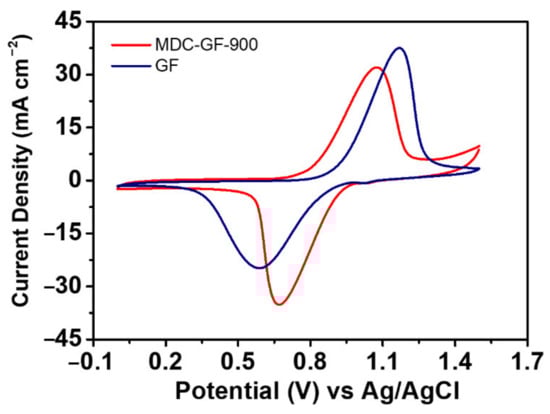
Figure 7.
CV curves of MDC-GF-900 and pristine GF obtained at the scan rate of 5 mV s−1. The electrolyte was composed of 0.05 M VOSO4 plus 2.0 M H2SO4.
2.3. VRFB Single Cell Performance
Graphite felts modified by MDC-900 possessed superior electrochemical activity toward VO2+/VO2+, and the charge-discharge tests were conducted to realize VRFB performance at various current densities, including 80, 100, 120, and 140 mA cm−2. The VRFB assembled with MDC-GF-900 electrode is applied on the positive electrode, while the pristine GF electrode was used on the negative electrode. For comparison, the VRFB assembled with the same pristine GF electrode is employed on both sides. The cell performance was evaluated by using voltage efficiency (VE), coulombic efficiency (CE), and energy efficiency (EE). In Figure 8a, the onset potential of the charging stage of MDC-GF-900 is 36.69 mV lower than that of the pristine GF. On the other hand, in the discharging stage, the onset potential of MDC-GF-900 is 19.44 mV higher than that of the pristine GF. The phenomenon originated from reducing overpotential and internal resistance because MDC-900 possesses more active sites and the synergistic effect between ZrO2 and graphite structure. Specifically, the graphite structure with higher conductivity can help conduct the electrons coming from the active sites to the surface of electrodes. Moreover, MDC-900 has a high specific surface area that could facilitate the redox reaction rate and improve the accessibility of electrolytes. Thus, the process of charge transfer would carry on more smoothly.
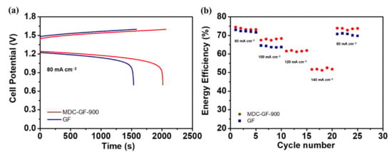
Figure 8.
The performance for charge-discharge tests of single cells using (a) MDC-GF-900 and GF electrodes at 80 mA cm−2; (b) The energy efficiency (EE) of single cells with different electrodes at 80, 100, 120, and 140 mA cm−2.
Figure 8b shows the EEs of VRFBs using MDC-GF-900 and pristine GF as cycle numbers at various current densities. Table 1 lists the VEs, the CEs, the EEs, and capacities of the VRFBs using MDC-GF-900 and pristine GF at different current densities. Firstly, for both VRFBs, the EE becomes lower as the current density increases because the polarization increases with increasing current density. Secondly, at 80 mA cm−2, the difference of EE between MDC-GF-900 and the pristine GF is only 1.3%, and MDC-GF-900 exhibits a more remarkable improvement of EE by 3.9% higher than that of GF at 100 mA cm−2, which is also comparable with previously reported ZrO2-based catalyst [39]. Furthermore, at 120 and 140 mA cm−2, the EEs of MDC-GF-900 still keeps 61.6% and 51.8%, respectively. However, the VRFB using the pristine GF is not able to show any results. Since the polarization of pristine GF is too high, it is challenging to conduct the charge-discharge process. Even in the last five cycles, as the current density returning to 80 mA cm−2, the EE of the pristine GF is about 1.8% lower than that of the first five cycles. Interestingly, on the other hand, MDC-GF-900 could perfectly maintain its EE as the current density returning from 140 to 80 mA cm−2. The superiority of MDC-GF-900 becomes even more substantial when the current density is further increased. The CE is affected by the battery or vanadium ions’ leakage through the membrane during the charge-discharge process. Therefore, the capacity can be considered the utilization of electrolytes for the VRFB. The capacities of MDC-GF-900 reveal 31% and 107% higher than those of the pristine GF at 80 and 100 mA cm−2, respectively. Even at 120 and 140 mA cm−2, MDC-GF-900 shows 356.9 and 70.2 mAh capacity, respectively, but the pristine GF cannot get any energy from the electrolytes during this situation. In other words, MDC-GF-900 improves the utilization rate of electrolytes and thus increases the capacity of VRFB. It represents the cost down of purchasing electrolytes for constructing and maintaining VRFB systems.

Table 1.
The VE, CE, and EE of VRFB single-cell tests with MDC-GF-900 and GF electrodes at 80, 100, 120, 140 mA cm−2.
To evaluate whether the performance of MDC-GF-900 can preserve or not after several charge-discharge cycles, the stability tests were conducted in Figure 9. From the results, the VE of MDC-GF-900 has no decline after 100 charge-discharge cycles at 100 mA cm−2, but it is declined from 66.7% to 64.2% for GF. Similarly, the CE and the EE of MDC-GF-900 also maintain well after several cycles, suggesting that the improved electrochemical activity of MDC-GF-900 can be retained for a long time. Figure 9d displays the discharge capacity of the MDC-GF-900 and GF measured at 100 mA cm−2 for 100 cycles. As shown in the figure, the VRFB delivered more than 71% total capacity retention instead of stable cycling performance after 100 cycles, which is much higher than GF (42%) and comparable to previously reported literature with minimum decay rates for VRFBs [40,41]. The slow capacity decay and stable EE demonstrate the outstanding cycling stability of the nanocomposite material that remained on the GF surface over succeeding cycles in the flowing electrolyte. Furthermore, to understand the stability of the catalyst on the GF, we have taken the SEM images before and after 100 cycles. As shown in Figure S2, after 100 cycles of charging and discharging operation under flowing electrolyte, the MDC-900 nanoparticles are still adhered to and uniformly distributed on the felt surface, which signifies better electrode stability. To sum up, MDC-GF-900 possesses favorable and stable electrochemical activity and can promote the capacity of VRFB. Therefore, by applying MDC-GF-900 in VRFB systems, the targets of increasing efficiency of operation, raising utilization rate of electrolyte, and maintaining high performance for a long time can all be achieved.
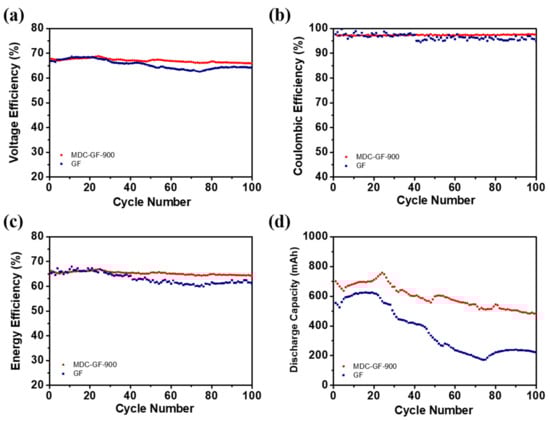
Figure 9.
(a) VE, (b) CV, (c) EE, and (d) discharge capacity of 100 charge-discharge cycles for the cell with MDC-GF-900 and GF at a current density of 100 mA cm−2.
To explain the electrocatalytic activity in VRFB, we intended to focus on the redox reaction of the VO2+/VO2+ couple on the surface of the MDC-GF-900 electrode. The detailed electrocatalytic process and the proposed mechanism on the electrode towards VO2+/VO2+ redox reaction are shown in the supporting information (Scheme S1). The catalytic mechanism can be explained in the following way. Like other transition metal oxides, the presence of oxygen bonding within ZrO2 might be the critical factor for the notable improvement in electrochemical activities of the MDC-GF-900 electrode [42]. As previously reported, the oxygen-containing functional groups (–OH, –COOH, –C=O, and –C–O) on the electrode surface probably behave as active sites, catalyzing the VO2+/VO2+ redox reactions [43]. It can be seen from this reaction mechanism that, for example, the charging and discharging process at the positive electrode involves the transfer of an oxygen atom, which is likely to be the rate-determining step in the overall mechanism [44]. First, VO2+ ions diffuse from the bulk electrolyte and ion exchange with H+ of the oxygen-containing functional groups on the surface, and then they bonded onto the electrode surface. Second, the electron transfer occurs from the VO2+ to the electrode along the ZrO2–V– bond and the transfer of one of the oxygen atoms on the functional group to the VO2+ forming VO2+. Finally, the VO2+ exchanges with H+ from the solution and diffuses back into the bulk solution. For the discharge process, reverse reactions would occur.
The outstanding performance of the MDC-GF-900 electrode can be ascribed to (1) the synergistic effects, which are related to the high electronic conductivity of the carbon material from MOF-derived material and interfacial properties created between the ZrO2 nanoparticles distributed on it, (2) the existence of oxygen-containing functional groups which acts as the active sites, and (3) the porous structures and an increase in the surface area, which can contribute to increasing the active sites on the surface to enhance the electrochemical performance of the cell.
3. Experiment Methods
3.1. Materials and Preparation
Zirconium-based MOF was synthesized referring to a previously reported procedure by Moghaddam et al. [45]. First, 125 mg of ZrCl4 (Acros Organic, Geel, Belgium) was dissolved in 5 mL dimethylformamide (DMF) (Acros Organic, Geel, Belgium) and 1 mL HCl (Scharlau, Barcelona, Spain) through ultrasonication for 10 min. Simultaneously, 125 mg of terephthalic acid (Acros Organic, Geel, Belgium) was dissolved in another 10 mL DMF under sonication for 10 min. Subsequently, these two solutions were mixed by using magnetic stirring and ultrasonication until well-distribution. Next, the mixture was heated at 80 °C for 12 h in a muffle furnace. When the reaction was completed, the MOF was separated from the solution by vacuum filtration, rinsed thoroughly with DMF and absolute ethanol, and dried overnight in a vacuum oven at 80 °C. To optimize MOF-derived catalyst activity, different sintering temperatures such as 500, 700, 900, and 1000 °C were applied on the as-prepared MOFs for 2 h in an argon atmosphere at a heating rate of 10 °C per minute. After the process, MDC (MOF–derived catalyst)-X (X = 500, 700, 900, 1000) were acquired and conducted for further measurements. On the other hand, pristine GF was preheated at 400 °C for 15 min in the microwave oven before decorating MOF-derived catalyst on GF. Then, heat-treated graphite felt (HGF) was placed inside the precursor solution of MOF and following the aforementioned synthetic steps.
3.2. VRFB Single-Cell Tests
The VRFB single cell tests were conducted in 1.6 M VOSO4 plus 4.6 M H2SO4 solution. The graphite felts (5 cm × 5 cm × 0.65 cm) with MOF-derived catalyst were applied on the positive electrode, and the pristine GF was applied on the negative electrode. Nafion 212 membrane was used as an ion-exchange membrane (DuPont) sandwiched in the middle of VRFB by the cell frames. The storage chambers of both side electrolytes were 60 mL which were circulated by two FMI pumps (Fluid Metering, Inc., Syosset, NY, USA) separately at the flow rate of 80 mL min−1. Before the charge-discharge tests began, nitrogen gas was purged to remove oxygen from the electrolyte. Moreover, the potential range of charge-discharge tests was between 0.7 and 1.6 V. Different current densities, such as 80, 100, 120, 140, and 160 mA cm−2, were applied in the measurements to evaluate their columbic efficiency (CE), energy efficiency (EE), and voltage efficiency (VE) (equation 1 to3). To compare cell performance with modified GFs, the pristine GFs were used as both electrodes for single-cell tests.
tc is the charging time, td is the discharging time, I is the current, Vc is the charging voltage, Vd is the discharging voltage, and Vd and Vc are time functions.
3.3. Physicochemical Characterization
The MOF-derived catalysts’ morphology was characterized through field emission scanning electron microscope (FE-SEM, JSM-6500F) (JEOL Ltd., Tokyo, Japan). The crystallite information such as d-spacing can be performed by X-ray field emission gun transmission electron microscope (FEG-TEM, FEI Tecnai™ G2 F-20 S-TWIN) (FEI Co., Northeast Dawson Creek Dr Hillsboro, OR, USA) through its high resolution and transmission ability. The phase and crystallographic structure of the samples were determined by X-ray diffraction (XRD, Bruker, D2-PHASER X-ray Diffractometer) (Bruker Corp., Billerica, MA, USA) with a Cu Kα radiation source of λ = 1.54 Å. To identify the bonding situations and structural defects of materials, a Raman spectrometer (iHR550) (Horiba Ltd., Kyoto, Japan) with 532 nm wavelength of the laser beam was applied by detecting the vibration states in molecules. The binding energy between surface atoms of materials can be measured using X-ray photoelectron spectroscopy (XPS, Thermo, K-Alpha) (Thermo Fisher Scientific Inc., Waltham, MA, USA) analysis, providing strong evidence of bonding and chemical compositions of the samples. Brunauer–Emmett–Teller (BET, Quantachrome Instruments, NOVA touch LX2) (Quantachrome Instruments, Boynton Beach, FL, USA) analysis was used to check materials’ specific surface area and porosity by adsorption-desorption of nitrogen gas.
3.4. Electrochemical Characterization
The cyclic voltammetry (CV) was performed through a typical three-electrode measurement using an electrochemical workstation (Bio-Logic, VSP-300) (Bio-Logic Science Instruments, Seyssinet-Pariset, France). A glassy carbon ring disk electrode (RDE) was used as a working electrode. Counter and reference electrodes were platinum wire and Ag/AgCl, respectively. The ink dropped onto RDE was composed of a 7.5 mg catalyst, 2.8 mL isopropanol, 2.8 mL DI water, and 0.04 mL of 5 wt% Nafion solution, and the electrolyte of RDE tests contained 1.6 M VOSO4 plus 4.6 M H2SO4 solution. The scan range was from 0 to 1.5 V, and the scan rate was 10 mV s−1. The electrochemical impedance spectroscopy (EIS) test was conducted at room temperature in the frequency range from 100 kHz to 10 MHz at applied potential of 1.0 V.
On the other hand, in the CV tests of the GFs electrode, the GFs were cut with the circular shape (geometric area of 1.327 cm2) and employed as the working electrodes. 0.05 M VOSO4 in a 2 M H2SO4 was prepared and utilized as an electrolyte in this case. The potential range and the scan rate were 0 to 1.5 V and 5 mV s−1, respectively. Nitrogen gas was purged to prevent side reactions like oxygen evolution reaction during the CV tests.
4. Conclusions
In summary, metal-organic frameworks–derived catalysts (MDC) have been prepared through carbonization techniques at different sintering temperatures. The prepared samples were characterized by several techniques, such as XRD, Raman spectra, SEM, TEM, BET, and XPS, confirming the successful fabrication of zirconium-based MOF–derived catalysts. Furthermore, the cyclic voltammetry results show that the optimum zirconium-based MOF–derived catalyst (MDC-900) reveals the highest electrochemical performance for VO2+/VO2+ redox reaction. Furthermore, the MDC-GF-900 electrode delivers high EE, which is 3.9% more efficient than the pristine GF at 100 mA cm−2, and shows good stability. The excellent performance of MDC-GF-900 arises from the existence of oxygen-containing functional groups active sites, graphite structure with high conductivity embedded with ZrO2, and high surface area, which play an excellent role in promoting the vanadium redox reactions.
Supplementary Materials
The following are available online at https://www.mdpi.com/article/10.3390/catal11101188/s1, Scheme S1. Schematic illustration of the mechanism for the VO2+/VO2+ redox reaction occurring in the presence of MDC-GF-900 electrode, Scheme S2. Schematic diagram showing the synthesis of MDC-GF-900 electrode and its effects towards the catalytic activity of the electrode, Figure S1. CV curves of negative electrode obtained at the scan rate of 10 mV s−1. The electrolyte was composed of 1.6 M VOSO4 plus 4.6 M H2SO4, Figure S2. The SEM images of MDC-GF-900 with different magnifications: (a) before stability test, and (b) after 100 cycles stability test.
Author Contributions
Conceptualization, Y.-T.O. and C.-H.W.; methodology, Y.-T.O.; software, Y.-T.O. and H.-C.H.; validation, A.W.B.; formal analysis, Y.-T.O.; investigation, H.-H.K., Y.-L.K., Y.-M.W. and T.-C.C.; resources, C.-H.W.; data curation, A.W.B.; writing—original draft preparation, Y.-T.O.; writing—review and editing, D.M.K., A.W.B. and C.-H.W.; supervision, D.M.K. and C.-H.W.; project administration, C.-H.W.; funding acquisition, H.-H.K. and N.-Y.H. All authors have read and agreed to the published version of the manuscript.
Funding
This research was funded by the Ministry of Science and Technology (MOST) of Taiwan (Grant number: MOST 107-2628-E-011-001-MY3 and MOST 109-2622-E-011-025-), CHANG BAU INDUSTRIAL CO., LTD. (Grant number: MOST 109-2622-E-011-025-), Institute of Nuclear Energy Research, Atomic Energy Council, Executive Yuan (Grant number: 110-D0114), and the Hierarchical Green-Energy Materials (Hi-GEM) Research Center, from The Featured Areas Research Center Program within the Higher Education Sprout Project framework by the Ministry of Education of Taiwan.
Data Availability Statement
The raw/processed data required to reproduce these findings cannot be shared at this time as the data also forms part of an ongoing study.
Acknowledgments
This study was financially supported mainly by the Ministry of Science and Technology (MOST) of Taiwan (Grant number: MOST 107-2628-E-011-001-MY3), and the cooperation project of MOST with CHANG BAU INDUSTRIAL CO., LTD. was financially involved in this work (Grant number: MOST 109-2622-E-011-025-). In addition, the Institute of Nuclear Energy Research, Atomic Energy Council, Executive Yuan (Grant number: 110-D0114), and the Hierarchical Green-Energy Materials (Hi-GEM) Research Center, from The Featured Areas Research Center Program within the Higher Education Sprout Project framework by the Ministry of Education of Taiwan, both also provided funding to this research.
Conflicts of Interest
The authors declare that they have no known competing financial interests or personal relationships that could have appeared to influence the work reported in this paper.
References
- Bayeh, A.W.; Kabtamu, D.M.; Chang, Y.-C.; Chen, G.-C.; Chen, H.-Y.; Lin, G.-Y.; Liu, T.-R.; Wondimu, T.H.; Wang, K.-C.; Wang, C.-H. Synergistic effects of a TiNb2O7–reduced graphene oxide nanocomposite electrocatalyst for high-performance all-vanadium redox flow batteries. J. Mater. Chem. A 2018, 6, 13908–13917. [Google Scholar] [CrossRef]
- Kabtamu, D.M.; Chen, J.-Y.; Chang, Y.-C.; Wang, C.-H. Electrocatalytic activity of Nb-doped hexagonal WO3 nanowire-modified graphite felt as a positive electrode for vanadium redox flow batteries. J. Mater. Chem. A 2016, 4, 11472–11480. [Google Scholar] [CrossRef]
- Sum, E.; Rychcik, M.; Skyllas-kazacos, M. Investigation of the V (V)/V (IV) system for use in the positive half-cell of a redox battery. J. Power Sources 1985, 16, 85–95. [Google Scholar] [CrossRef]
- Sum, E.; Skyllas-Kazacos, M. A study of the V (II)/V (III) redox couple for redox flow cell applications. J. Power Sources 1985, 15, 179–190. [Google Scholar] [CrossRef]
- Xiang, Y.; Daoud, W.A. Electrochemical Enhancement of Carbon Paper by Indium Modification for the Positive Side of Vanadium Redox Flow Battery. J. Electrochem. Soc. 2017, 164, A2256–A2261. [Google Scholar] [CrossRef]
- Wang, W.H.; Wang, X.D. Investigation of Ir-modified carbon felt as the positive electrode of an all-vanadium redox flow battery. Electrochim. Acta 2007, 52, 6755–6762. [Google Scholar] [CrossRef]
- Tseng, T.-M.; Huang, R.-H.; Huang, C.-Y.; Hsueh, K.-L.; Shieu, F.-S. Improvement of Titanium Dioxide Addition on Carbon Black Composite for Negative Electrode in Vanadium Redox Flow Battery. J. Electrochem. Soc. 2013, 160, A1269–A1275. [Google Scholar] [CrossRef] [Green Version]
- Li, B.; Gu, M.; Nie, Z.; Wei, X.; Wang, C.; Sprenkle, V.; Wang, W. Nanorod Niobium Oxide as Powerful Catalysts for an All Vanadium Redox Flow Battery. Nano Lett. 2014, 14, 158–165. [Google Scholar] [CrossRef]
- Bayeh, A.W.; Kabtamu, D.M.; Chang, Y.-C.; Chen, G.-C.; Chen, H.-Y.; Lin, G.-Y.; Liu, T.-R.; Wondimu, T.H.; Wang, K.-C.; Wang, C.-H. Ta2O5-Nanoparticle-Modified Graphite Felt As a High-Performance Electrode for a Vanadium Redox Flow Battery. ACS Sustain. Chem. Eng. 2018, 6, 3019–3028. [Google Scholar] [CrossRef]
- Bayeh, A.W.; Kabtamu, D.M.; Chang, Y.-C.; Chen, G.-C.; Chen, H.-Y.; Liu, T.-R.; Wondimu, T.H.; Wang, K.-C.; Wang, C.-H. Hydrogen-Treated Defect-Rich W18O49 Nanowire-Modified Graphite Felt as High-Performance Electrode for Vanadium Redox Flow Battery. ACS Appl. Energy Mater. 2019, 2, 2541–2551. [Google Scholar] [CrossRef]
- Bayeh, A.W.; Lin, G.-Y.; Chang, Y.-C.; Kabtamu, D.M.; Chen, G.-C.; Chen, H.-Y.; Wang, K.-C.; Wang, Y.-M.; Chiang, T.-C.; Huang, H.-C.; et al. Oxygen-Vacancy-Rich Cubic CeO2 Nanowires as Catalysts for Vanadium Redox Flow Batteries. ACS Sustain. Chem. Eng. 2020, 8, 16757–16765. [Google Scholar] [CrossRef]
- Li, W.; Liu, J.; Yan, C. Multi-walled carbon nanotubes used as an electrode reaction catalyst for VO2+/VO2+ for a vanadium redox flow battery. Carbon 2011, 49, 3463–3470. [Google Scholar] [CrossRef]
- Li, W.; Liu, J.; Yan, C. The electrochemical catalytic activity of single-walled carbon nanotubes towards VO2+/VO2+ and V3+/V2+ redox pairs for an all vanadium redox flow battery. Electrochim. Acta 2012, 79, 102–108. [Google Scholar] [CrossRef]
- Xia, L.; Zhang, Q.; Wu, C.; Liu, Y.; Ding, M.; Ye, J.; Cheng, Y.; Jia, C. Graphene coated carbon felt as a high-performance electrode for all vanadium redox flow batteries. Surf. Coat. Technol. 2019, 358, 153–158. [Google Scholar] [CrossRef]
- Kabtamu, D.M.; Chang, Y.-C.; Lin, G.-Y.; Bayeh, A.W.; Chen, J.-Y.; Wondimu, T.H.; Wang, C.-H. Three-dimensional annealed WO3 nanowire/graphene foam as an electrocatalytic material for all vanadium redox flow batteries. Sustain. Energy Fuels 2017, 1, 2091–2100. [Google Scholar] [CrossRef]
- Abbas, S.; Lee, H.; Hwang, J.; Mehmood, A.; Shin, H.-J.; Mehboob, S.; Lee, J.-Y.; Ha, H.Y. A novel approach for forming carbon nanorods on the surface of carbon felt electrode by catalytic etching for high-performance vanadium redox flow battery. Carbon 2018, 128, 31–37. [Google Scholar] [CrossRef]
- Bayeh, A.W.; Kabtamu, D.M.; Chang, Y.-C.; Wondimu, T.H.; Huang, H.-C.; Wang, C.-H. Carbon and metal-based catalysts for vanadium redox flow batteries: A perspective and review of recent progress. Sustain. Energy Fuels 2021, 5, 1668–1707. [Google Scholar] [CrossRef]
- Kung, C.-W.; Han, P.-C.; Chuang, C.-H.; Wu, K.C.W. Electronically conductive metal–organic framework-based materials. APL Mater. 2019, 7, 110902. [Google Scholar] [CrossRef] [Green Version]
- Kabtamu, D.M.; Wu, Y.-n.; Li, F. Hierarchically porous metal–organic frameworks: Synthesis strategies, structure(s), and emerging applications in decontamination. J. Hazard. Mater. 2020, 397, 122765. [Google Scholar] [CrossRef]
- Narayan, T.C.; Miyakai, T.; Seki, S.; Dincă, M. High Charge Mobility in a Tetrathiafulvalene-Based Microporous Metal–Organic Framework. J. Am. Chem. Soc. 2012, 134, 12932–12935. [Google Scholar] [CrossRef] [Green Version]
- Goswami, S.; Ray, D.; Otake, K.-i.; Kung, C.-W.; Garibay, S.J.; Islamoglu, T.; Atilgan, A.; Cui, Y.; Cramer, C.J.; Farha, O.K.; et al. A porous, electrically conductive hexa-zirconium(iv) metal–organic framework. Chem. Sci. 2018, 9, 4477–4482. [Google Scholar] [CrossRef]
- Micheroni, D.; Lan, G.; Lin, W. Efficient Electrocatalytic Proton Reduction with Carbon Nanotube-Supported Metal–Organic Frameworks. J. Am. Chem. Soc. 2018, 140, 15591–15595. [Google Scholar] [CrossRef]
- Jahan, M.; Bao, Q.; Loh, K.P. Electrocatalytically Active Graphene–Porphyrin MOF Composite for Oxygen Reduction Reaction. J. Am. Chem. Soc. 2012, 134, 6707–6713. [Google Scholar] [CrossRef]
- Zhang, Y.; Bo, X.; Nsabimana, A.; Han, C.; Li, M.; Guo, L. Electrocatalytically active cobalt-based metal–organic framework with incorporated macroporous carbon composite for electrochemical applications. J. Mater. Chem. A 2015, 3, 732–738. [Google Scholar] [CrossRef]
- Fu, S.; Zhu, C.; Song, J.; Du, D.; Lin, Y. Metal-Organic Framework-Derived Non-Precious Metal Nanocatalysts for Oxygen Reduction Reaction. Adv. Energy Mater. 2017, 7, 1700363. [Google Scholar] [CrossRef]
- Li, Y.; Kim, J.; Wang, J.; Liu, N.-L.; Bando, Y.; Alshehri, A.A.; Yamauchi, Y.; Hou, C.-H.; Wu, K.C.W. High performance capacitive deionization using modified ZIF-8-derived, N-doped porous carbon with improved conductivity. Nanoscale 2018, 10, 14852–14859. [Google Scholar] [CrossRef] [PubMed]
- Ge, Z.; Wang, L.; He, Z.; Li, Y.; Jiang, Y.; Meng, W.; Dai, L. Electrocatalytic activity of cobalt phosphide-modified graphite felt toward VO2+/VO2+ redox reaction. Appl. Surf. Sci. 2018, 436, 1030–1037. [Google Scholar] [CrossRef]
- Noh, C.; Lee, C.S.; Chi, W.S.; Chung, Y.; Kim, J.H.; Kwon, Y. Vanadium Redox Flow Battery Using Electrocatalyst Decorated with Nitrogen-Doped Carbon Nanotubes Derived from Metal-Organic Frameworks. J. Electrochem. Soc. 2018, 165, A1388–A1399. [Google Scholar] [CrossRef]
- Li, Y.; Ma, L.; Yi, Z.; Zhao, Y.; Mao, J.; Yang, S.; Ruan, W.; Xiao, D.; Mubarak, N.; Wu, J.; et al. Metal–organic framework-derived carbon as a positive electrode for high-performance vanadium redox flow batteries. J. Mater. Chem. A 2021, 9, 5648–5656. [Google Scholar] [CrossRef]
- Katz, M.J.; Brown, Z.J.; Colón, Y.J.; Siu, P.W.; Scheidt, K.A.; Snurr, R.Q.; Hupp, J.T.; Farha, O.K. A facile synthesis of UiO-66, UiO-67 and their derivatives. Chem. Commun. 2013, 49, 9449–9451. [Google Scholar] [CrossRef]
- Shearer, G.C.; Chavan, S.; Ethiraj, J.; Vitillo, J.G.; Svelle, S.; Olsbye, U.; Lamberti, C.; Bordiga, S.; Lillerud, K.P. Tuned to Perfection: Ironing Out the Defects in Metal–Organic Framework UiO-66. Chem. Mater. 2014, 26, 4068–4071. [Google Scholar] [CrossRef]
- Naumenko, A.P.; Berezovska, N.I.; Biliy, M.M.; Shevchenko, O.V. Vibrational Analysis and Raman Spectra of Tetragonal Zirconia. Phys. Chem. Solid State 2007, 9, 121–125. [Google Scholar]
- Quintard, P.E.; Barbéris, P.; Mirgorodsky, A.P.; Merle-Méjean, T. Comparative Lattice-Dynamical Study of the Raman Spectra of Monoclinic and Tetragonal Phases of Zirconia and Hafnia. J. Am. Ceram. Soc. 2002, 85, 1745–1749. [Google Scholar] [CrossRef]
- Wang, S.; Zhao, X.; Cochell, T.; Manthiram, A. Nitrogen-Doped Carbon Nanotube/Graphite Felts as Advanced Electrode Materials for Vanadium Redox Flow Batteries. J. Phys. Chem. Lett. 2012, 3, 2164–2167. [Google Scholar] [CrossRef] [PubMed]
- Wu, T.; Huang, K.; Liu, S.; Zhuang, S.; Fang, D.; Li, S.; Lu, D.; Su, A. Hydrothermal ammoniated treatment of PAN-graphite felt for vanadium redox flow battery. J. Solid State Electrochem. 2012, 16, 579–585. [Google Scholar] [CrossRef]
- Teeparthi, S.R.; Awin, E.W.; Kumar, R. Dominating role of crystal structure over defect chemistry in black and white zirconia on visible light photocatalytic activity. Sci. Rep. 2018, 8, 5541. [Google Scholar] [CrossRef] [Green Version]
- Blume, R.; Rosenthal, D.; Tessonnier, J.-P.; Li, H.; Knop-Gericke, A.; Schlögl, R. Characterizing Graphitic Carbon with X-ray Photoelectron Spectroscopy: A Step-by-Step Approach. ChemCatChem 2015, 7, 2871–2881. [Google Scholar] [CrossRef] [Green Version]
- Kabtamu, D.M.; Chen, J.-Y.; Chang, Y.-C.; Wang, C.-H. Water-activated graphite felt as a high-performance electrode for vanadium redox flow batteries. J. Power Sources 2017, 341, 270–279. [Google Scholar] [CrossRef]
- Zhou, H.; Shen, Y.; Xi, J.; Qiu, X.; Chen, L. ZrO2-Nanoparticle-Modified Graphite Felt: Bifunctional Effects on Vanadium Flow Batteries. ACS Appl. Mater. Interfaces 2016, 8, 15369–15378. [Google Scholar] [CrossRef]
- Ji, Y.; Li, J.L.; Li, S.F.Y. Synergistic effect of the bifunctional polydopamine–Mn3O4 composite electrocatalyst for vanadium redox flow batteries. J. Mater. Chem. A 2017, 5, 15154–15166. [Google Scholar] [CrossRef]
- Kim, K.J.; Park, M.-S.; Kim, J.-H.; Hwang, U.; Lee, N.J.; Jeong, G.; Kim, Y.-J. Novel catalytic effects of Mn3O4 for all vanadium redox flow batteries. Chem. Commun. 2012, 48, 5455–5457. [Google Scholar] [CrossRef]
- Yao, C.; Zhang, H.; Liu, T.; Li, X.; Liu, Z. Carbon paper coated with supported tungsten trioxide as novel electrode for all-vanadium flow battery. J. Power Sources 2012, 218, 455–461. [Google Scholar] [CrossRef]
- Kim, K.J.; Park, M.-S.; Kim, Y.-J.; Kim, J.H.; Dou, S.X.; Skyllas-Kazacos, M. A technology review of electrodes and reaction mechanisms in vanadium redox flow batteries. J. Mater. Chem. A 2015, 3, 16913–16933. [Google Scholar] [CrossRef]
- Shen, Y.; Xu, H.; Xu, P.; Wu, X.; Dong, Y.; Lu, L. Electrochemical catalytic activity of tungsten trioxide- modified graphite felt toward VO2+/VO2+ redox reaction. Electrochim. Acta 2014, 132, 37–41. [Google Scholar] [CrossRef]
- Moghaddam, Z.S.; Kaykhaii, M.; Khajeh, M.; Oveisi, A.R. Synthesis of UiO-66-OH zirconium metal-organic framework and its application for selective extraction and trace determination of thorium in water samples by spectrophotometry. Spectrochim. Acta Part. A Mol. Biomol. Spectrosc. 2018, 194, 76–82. [Google Scholar] [CrossRef]
Publisher’s Note: MDPI stays neutral with regard to jurisdictional claims in published maps and institutional affiliations. |
© 2021 by the authors. Licensee MDPI, Basel, Switzerland. This article is an open access article distributed under the terms and conditions of the Creative Commons Attribution (CC BY) license (https://creativecommons.org/licenses/by/4.0/).