This subsection investigates the crosspoint ratios relative to a single crossbar for unidirectional strictly nonblocking Clos (USNBC) networks and identical strictly nonblocking folded Clos (ISNBC) networks. These ratios are compared to those of the corresponding traditional Clos networks.
4.1.1. Cost Evaluations of USNBC Networks
An
crossbar (
n inputs and
m outputs) has
crosspoints. In the proposed strictly nonblocking Clos networks,
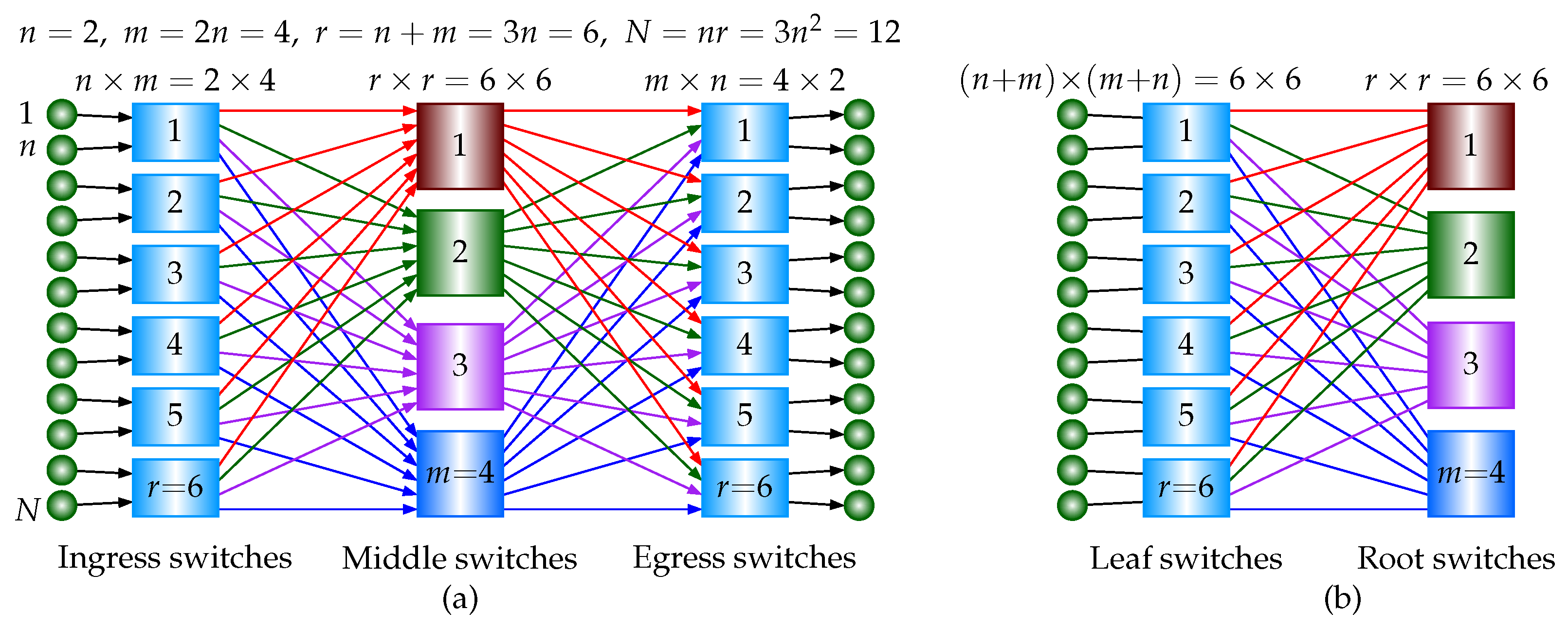
. Referring to
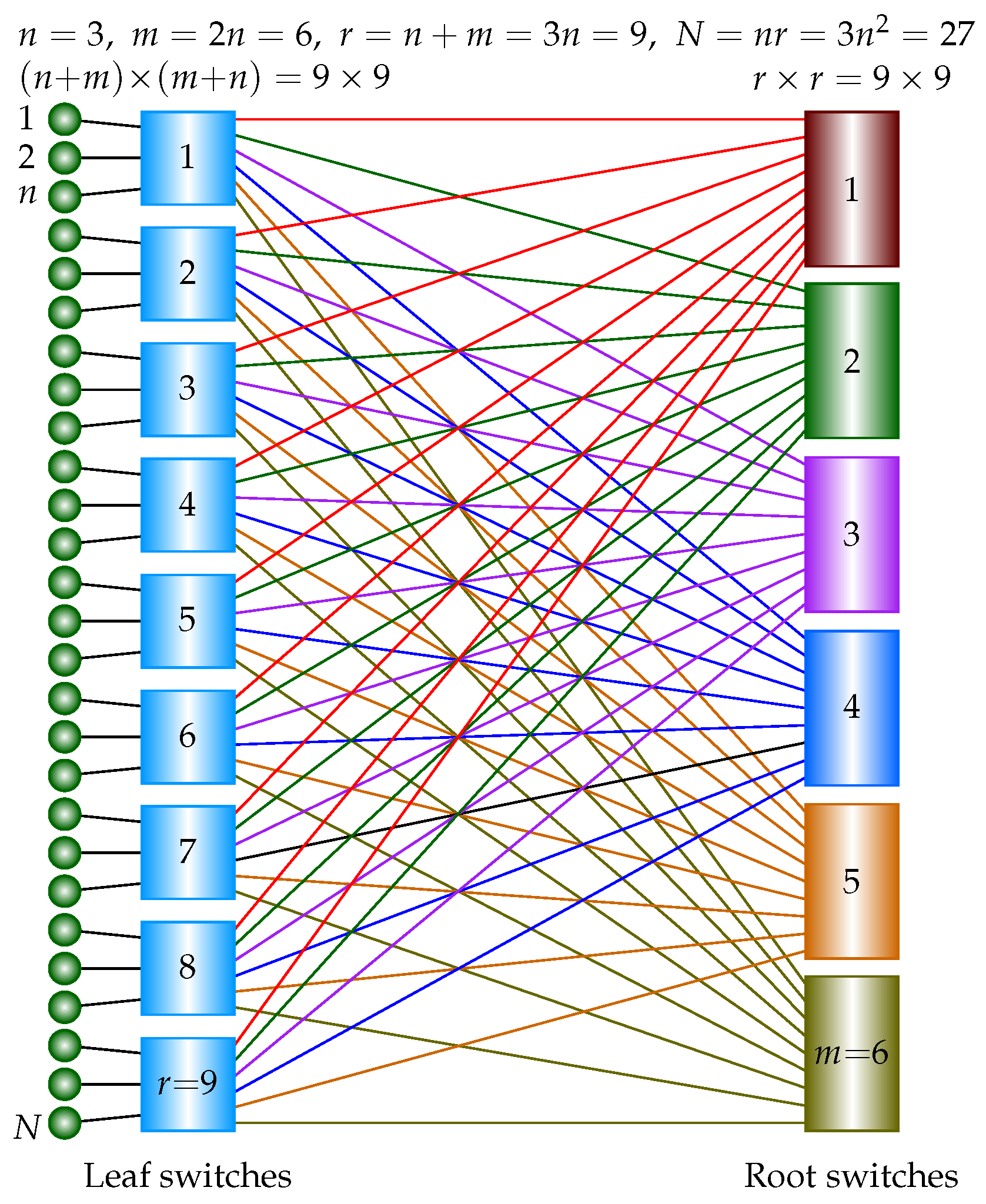
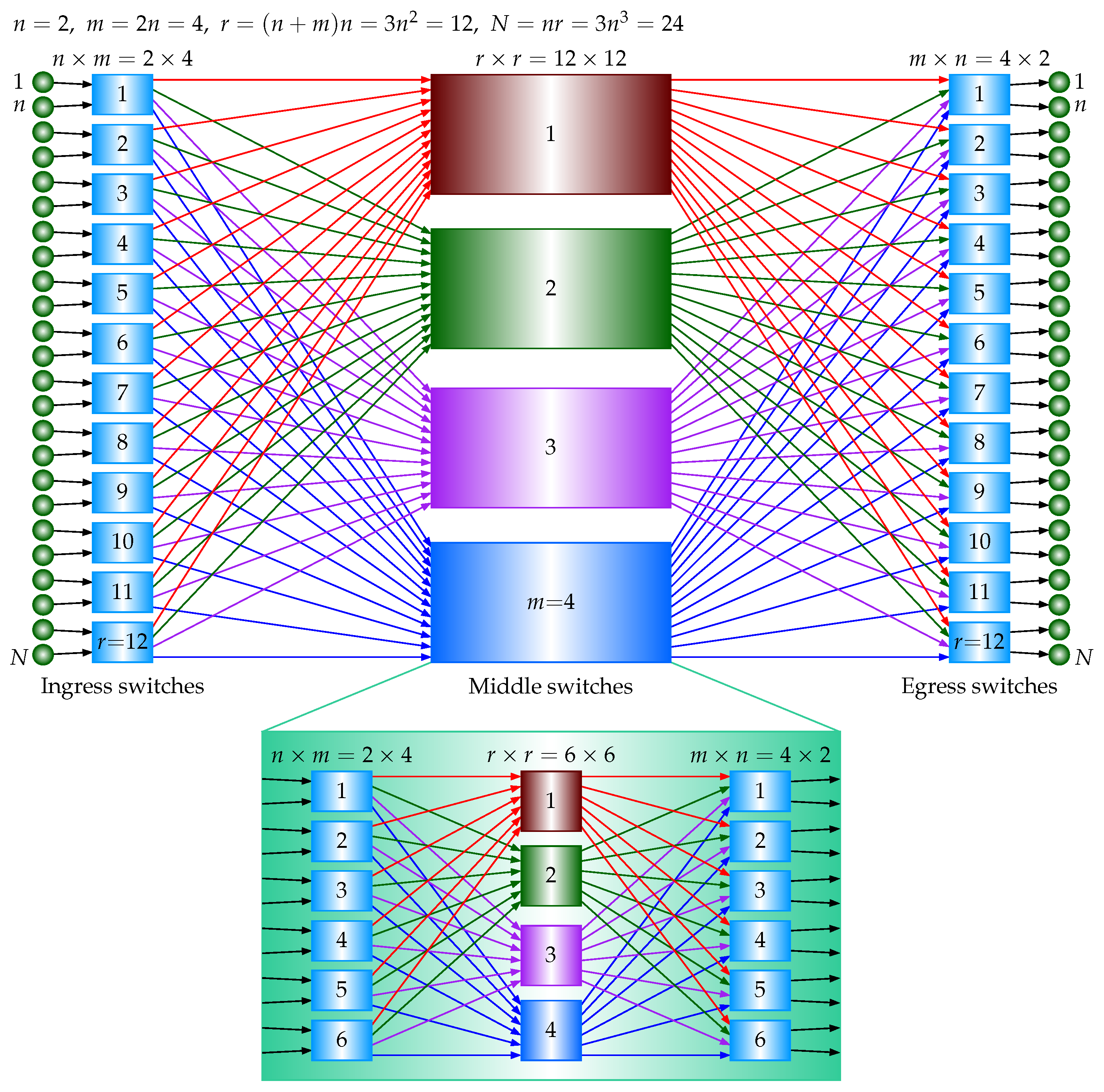
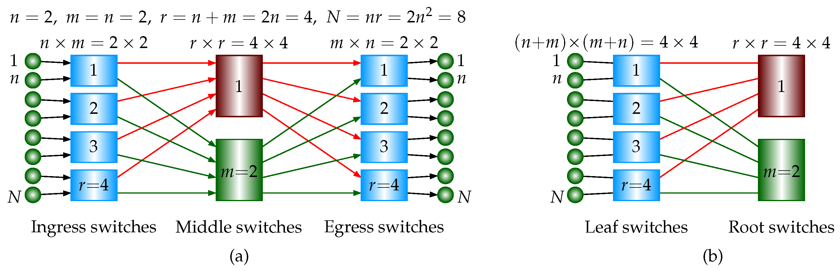
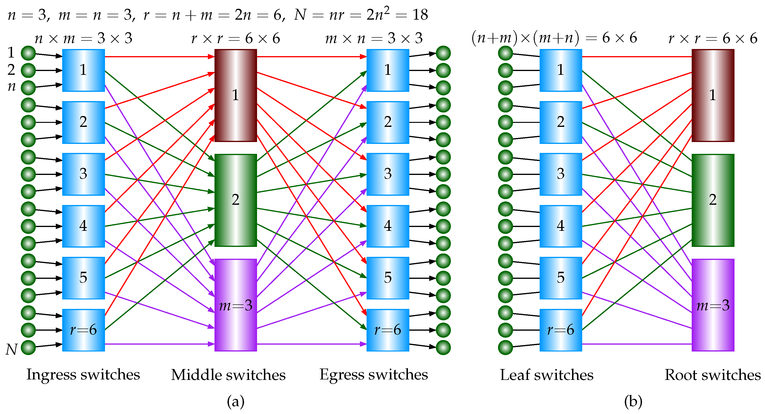
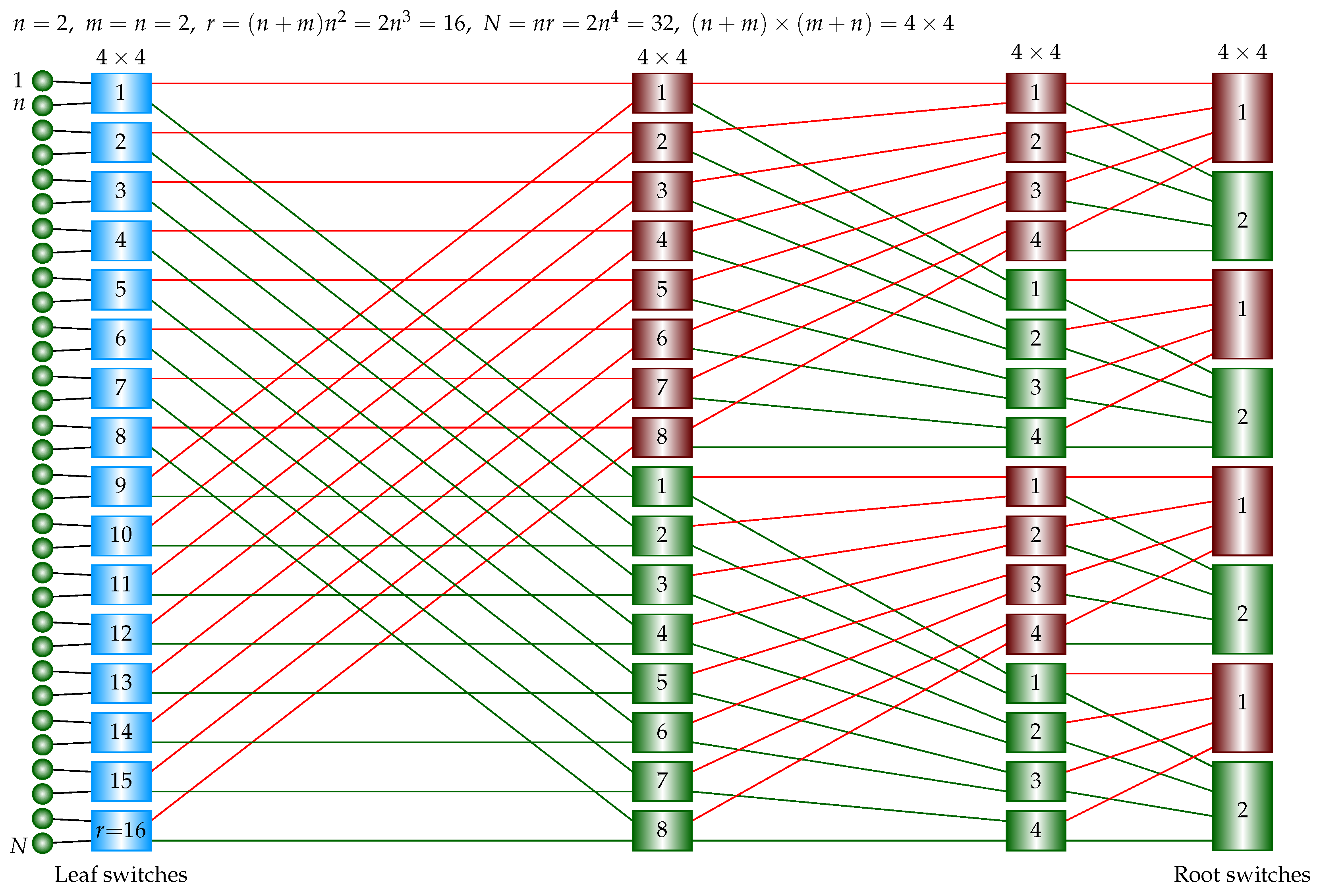
Figure 1a, in a three-stage USNBC network, there are
switches in the ingress stage, and each switch is an
crossbar. There are
m switches in the middle stage, and each switch is an
crossbar. There are
switches in the egress stage, and each switch is an
crossbar. The number of total crosspoints is
. There are
inputs and
outputs. A single
crossbar requires
crosspoints. The crosspoint ratio of the three-stage USNBC network relative to a single crossbar is
, which is less than 1 if
. For example, when
, the three-stage USNBC network requires
crosspoints, which is less than
crosspoints in the single crossbar’s implementation. In contrast, a traditional strictly nonblocking Clos network requires
, as mentioned in
Section 2.
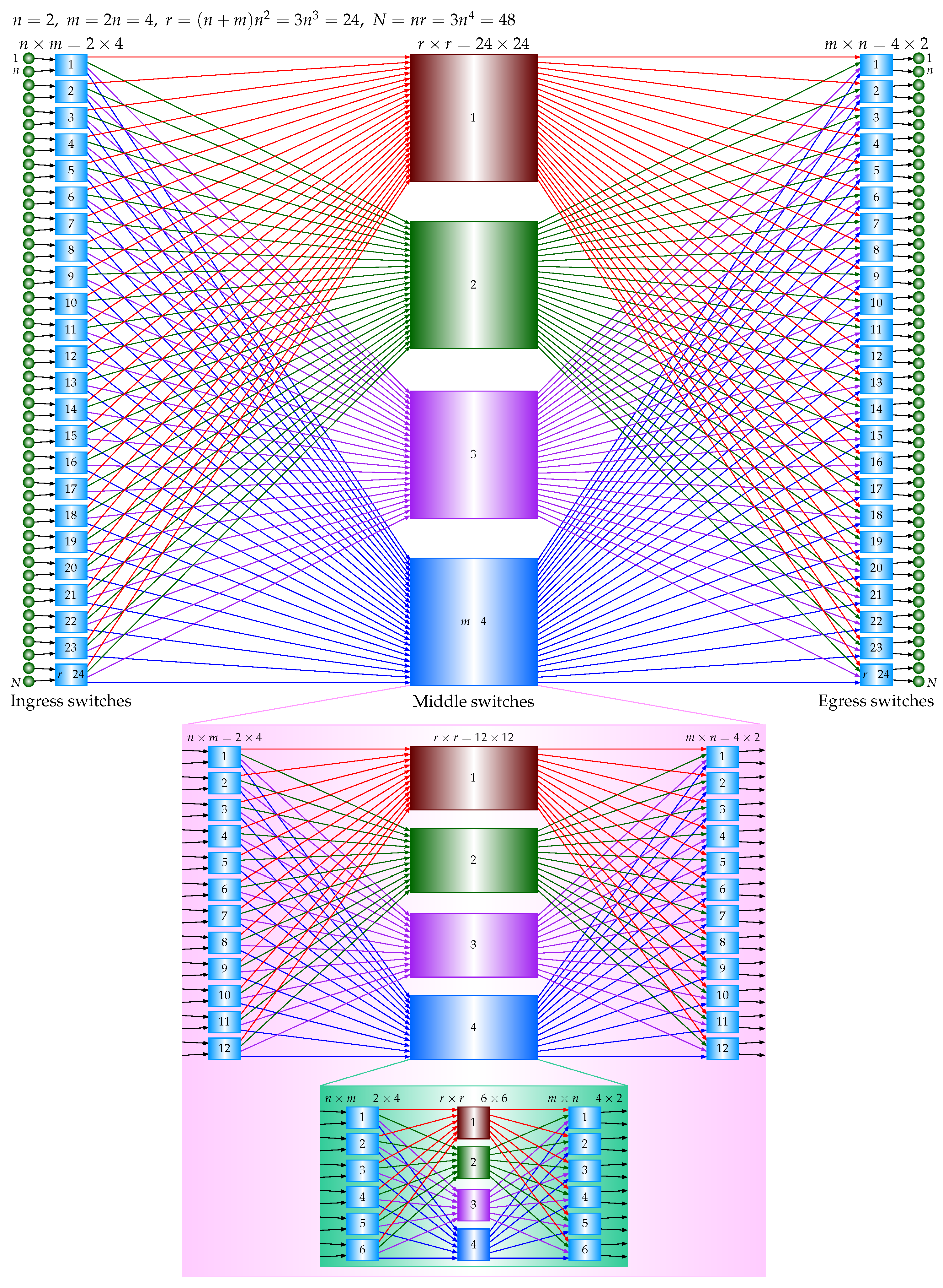
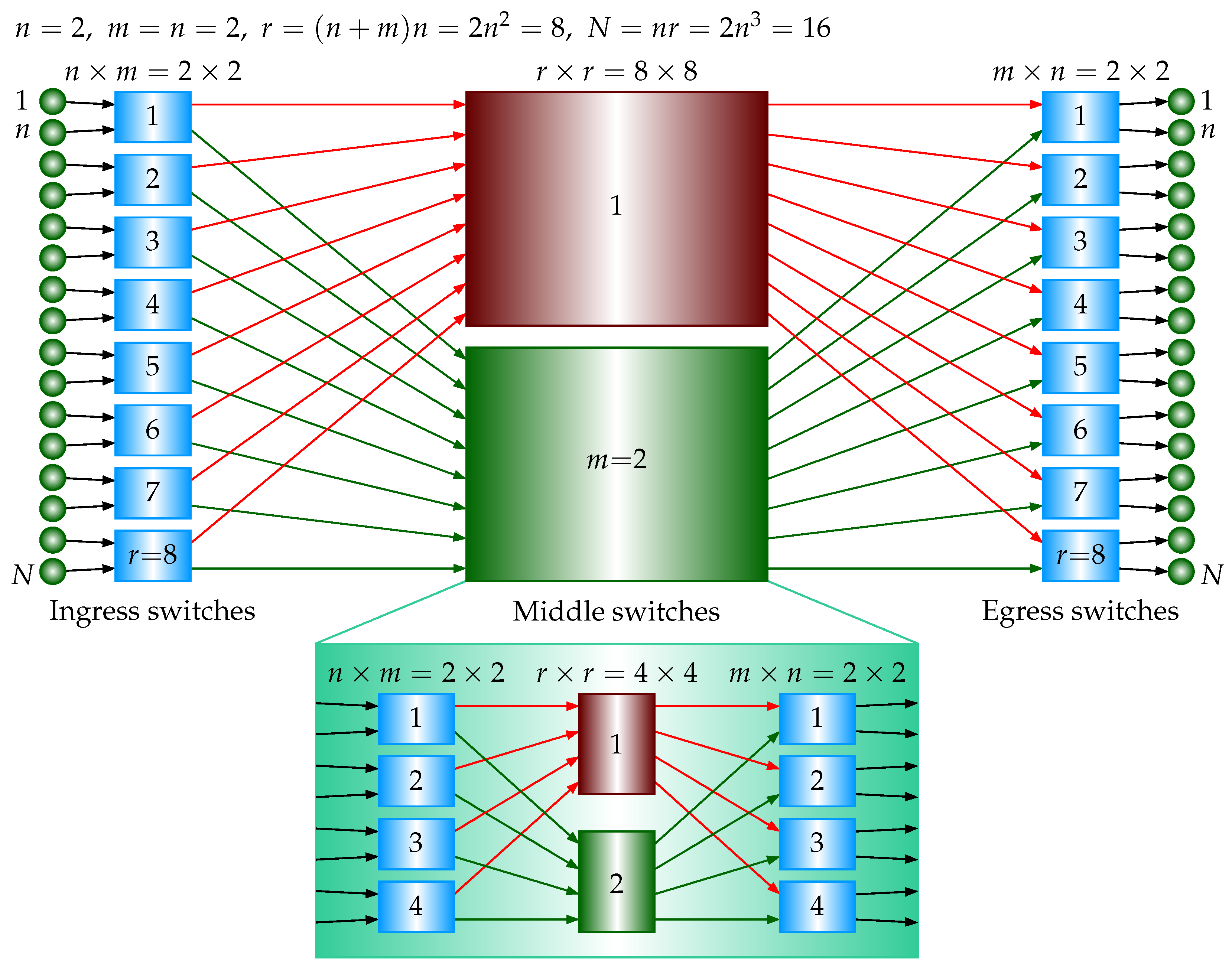
Referring to
Figure 6, in the five-stage case, there are
crosspoints in the ingress stage, there are
crosspoints in the middle stage, and there are
crosspoints in the egress stage, where
is the number of crosspoints in a three-stage USNBC network, as derived above. The total number of the crosspoints is
. There are
inputs and
outputs. A single
crossbar requires
crosspoints. The crosspoint ratio of the five-stage USNBC network relative to a single crossbar is
, which is less than 1 if
.
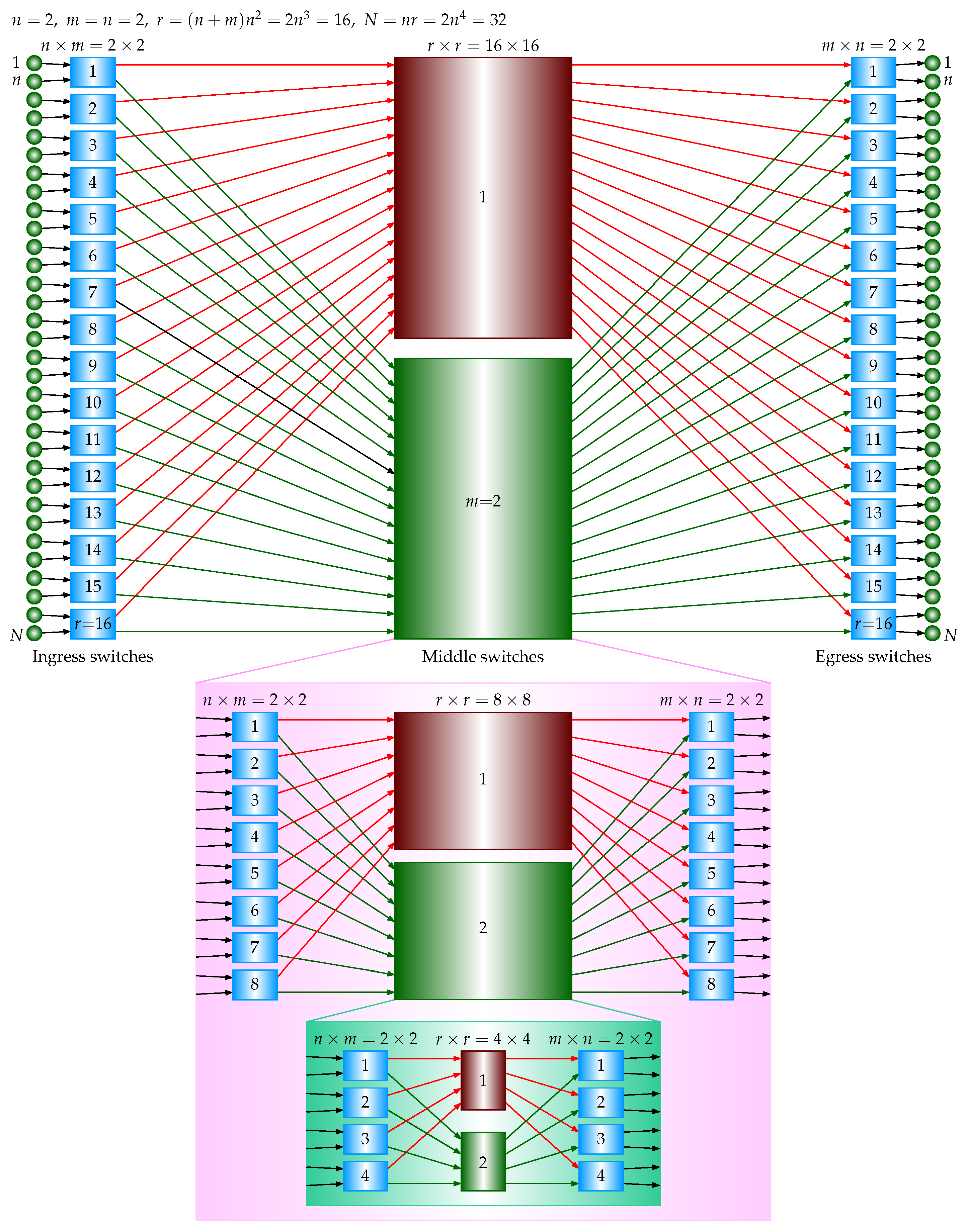
Referring to
Figure 8, in the seven-stage case, there are
crosspoints in the ingress stage, there are
crosspoints in the middle stage, and there are
crosspoints in the egress stage, where
is the number of crosspoints in a five-stage USNBC network, as derived above. The total number of the crosspoints is
. There are
inputs and
outputs. A single
crossbar requires
crosspoints. The crosspoint ratio of the seven-stage USNBC network relative to a single crossbar is
, which is less than 1 if
.
The number of crosspoints for a traditional unidirectional strictly nonblocking Clos network [
1] is examined below. A three-stage traditional unidirectional strictly nonblocking Clos network has
n switches in the ingress stage,
switches in the middle stage, and
n switches in the egress stage. An ingress-stage switch is an
crossbar, a middle-stage switch is an
crossbar, and an egress-stage switch is an
crossbar. Then, the total number of crosspoints is
. The total number of compute nodes is
. A single
crossbar requires
crosspoints. The crosspoint ratio of a three-stage traditional unidirectional strictly nonblocking Clos network relative to a single crossbar is
. To guarantee that the ratio is less than 1,
is needed.
Consider the five-stage case. There are crosspoints in the ingress stage, there are crosspoints in the middle stage, and there are crosspoints in the egress stage, where is the number of crosspoints in a three-stage traditional unidirectional strictly nonblocking Clos network, as derived above. The total number of crosspoints is . The total number of compute nodes is . A single crossbar requires crosspoints. The crosspoint ratio of a five-stage traditional unidirectional strictly nonblocking Clos network relative to a single crossbar is . To guarantee that the ratio is less than 1, is needed.
Consider the seven-stage case. There are crosspoints in the ingress stage, there are crosspoints in the middle stage, and there are crosspoints in the egress stage, where is the number of crosspoints in a five-stage traditional unidirectional strictly nonblocking Clos network, as derived above. The total number of crosspoints is . The total number of compute nodes is . A single crossbar requires crosspoints. The crosspoint ratio of a seven-stage traditional unidirectional strictly nonblocking Clos network relative to a single crossbar is . To guarantee that the ratio is less than 1, is needed.
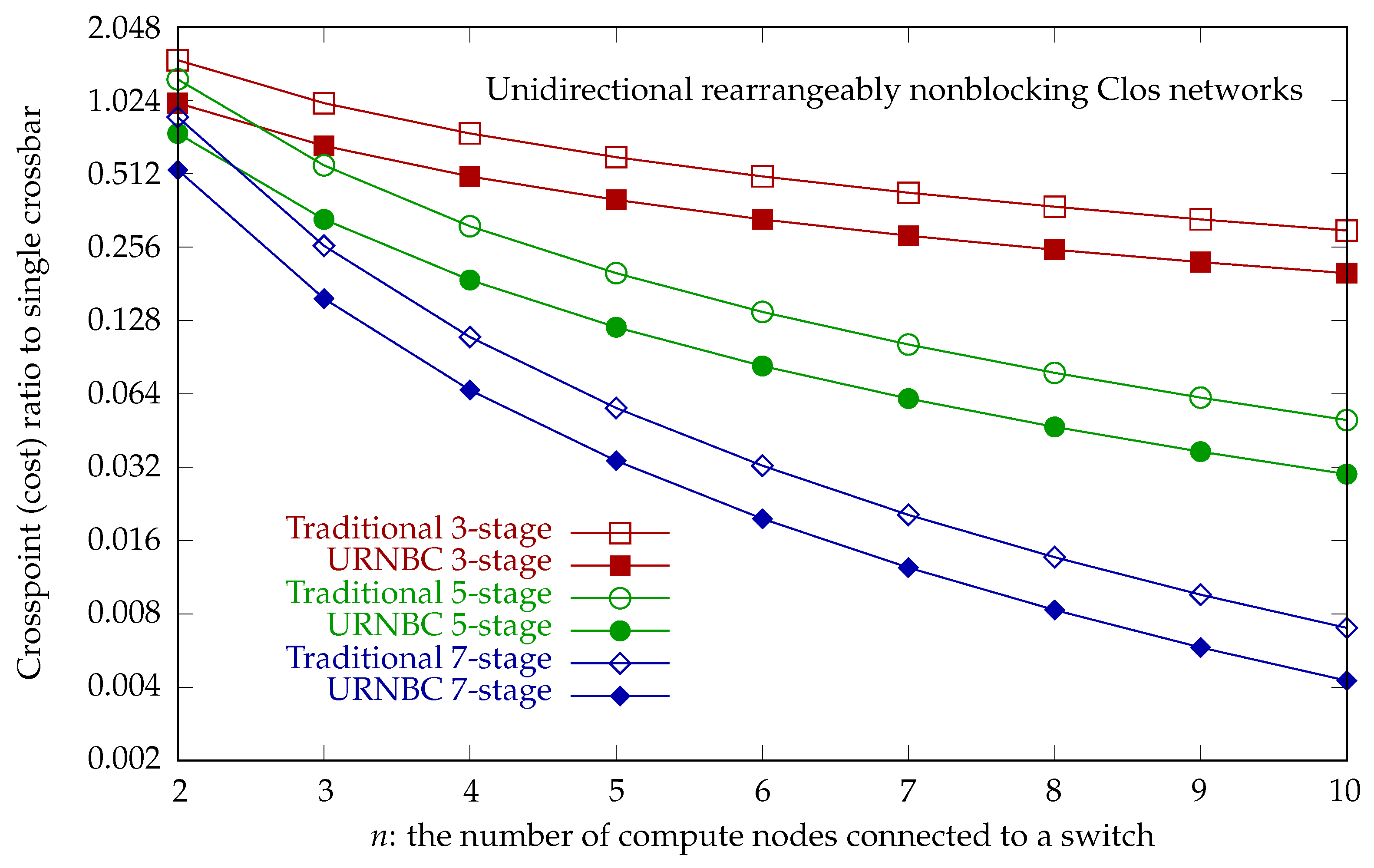
Table 9 summarizes the crosspoint ratio relative to a single crossbar for traditional unidirectional strictly nonblocking Clos networks and USNBC networks.
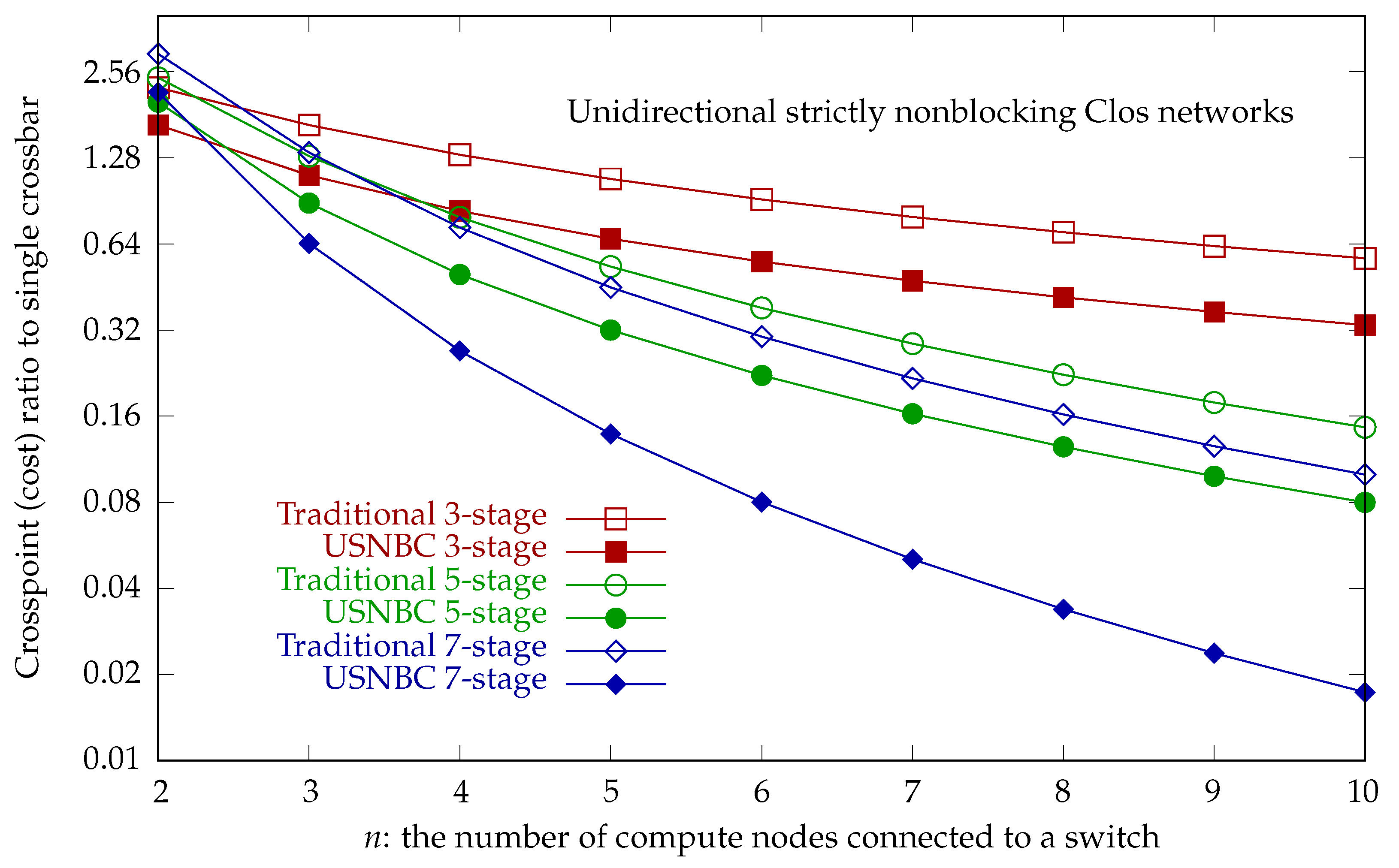
Figure 17 plots the crosspoint ratio relative to a single crossbar for unidirectional strictly nonblocking Clos networks, showing that USNBC networks have a lower crosspoint cost than traditional strictly nonblocking Clos networks.
4.1.2. Cost Evaluations of ISNBC Networks
The number of crosspoints for an ISNBC network that uses equally sized square crossbars of
for
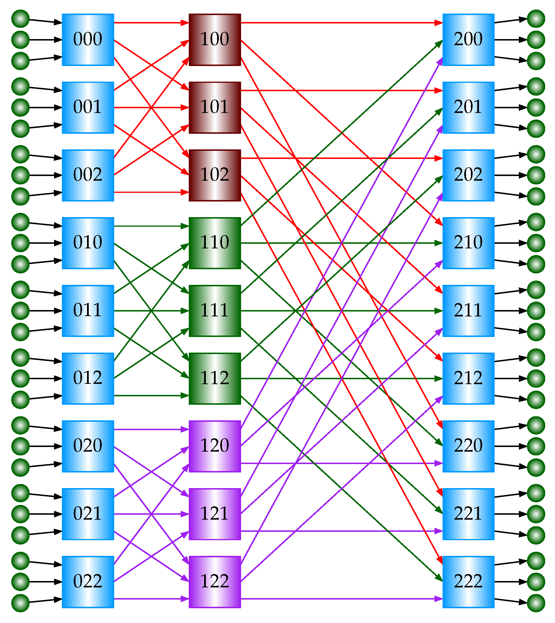
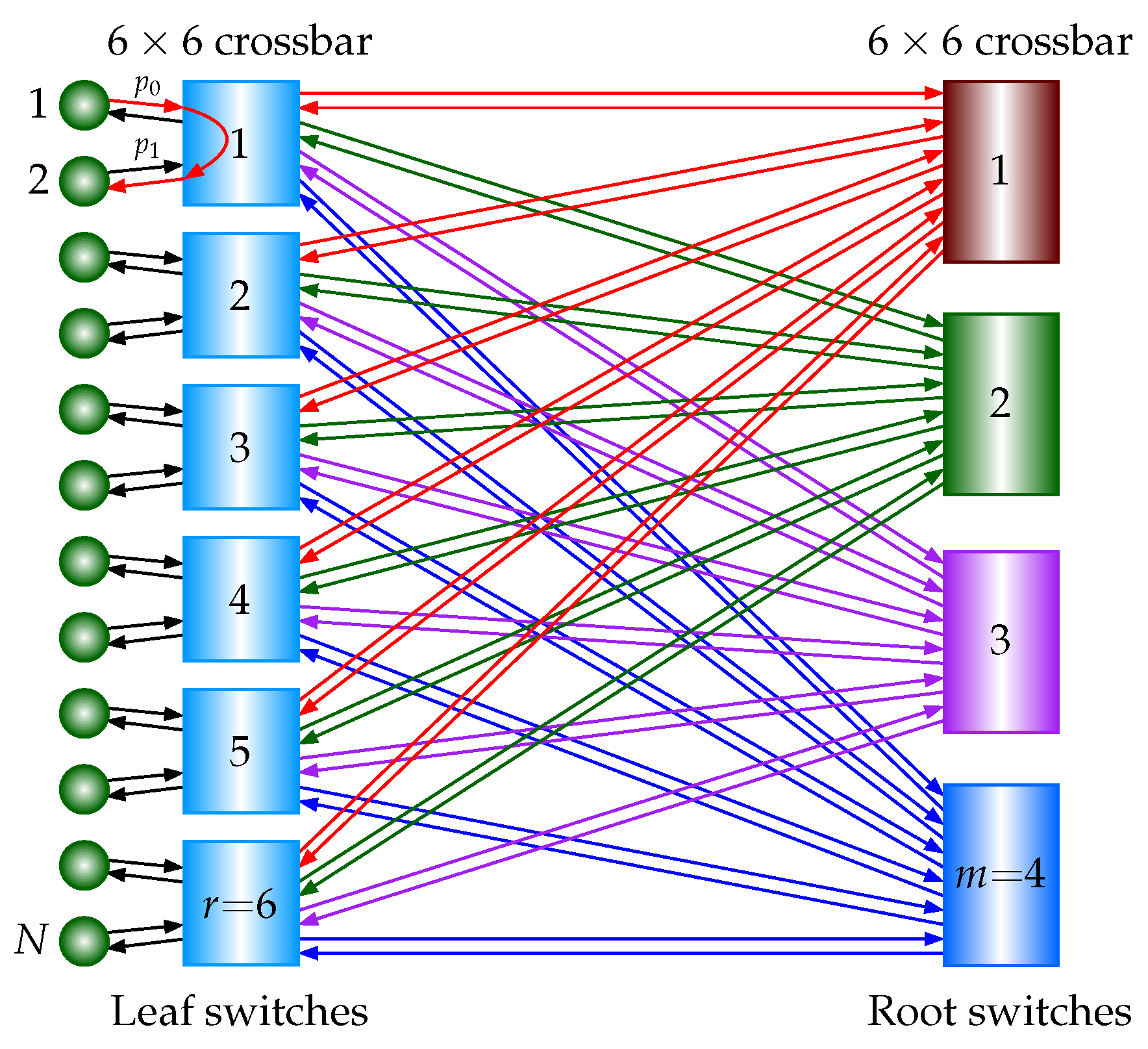
is examined below. Referring to
Figure 1b, an ISNBC network based on the three-stage USNBC network has two stages. There are
leaf switches and
m root switches. The total number of switches is
, and each switch is a square
crossbar. Then, the total number of crosspoints is
. The total number of compute nodes is
.
A single crossbar requires crosspoints. The crosspoint ratio of a two-stage ISNBC network relative to a single crossbar is . To guarantee that the ratio is less than 1, is needed.
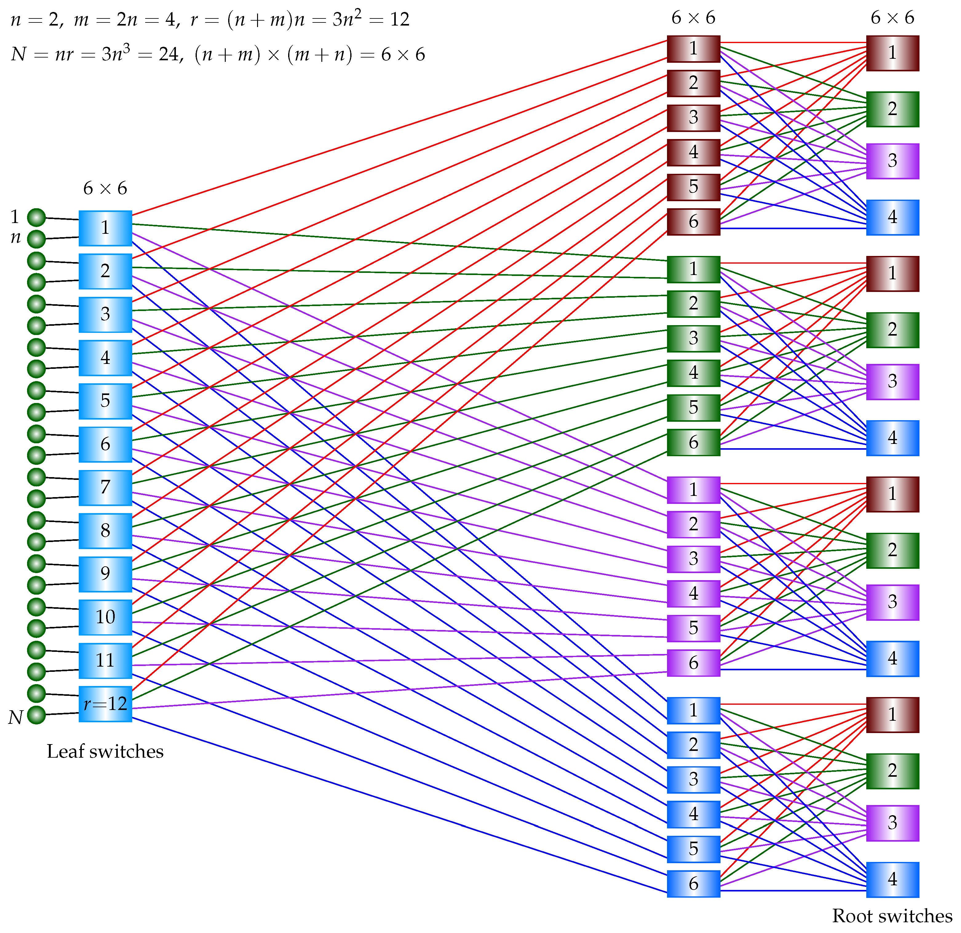
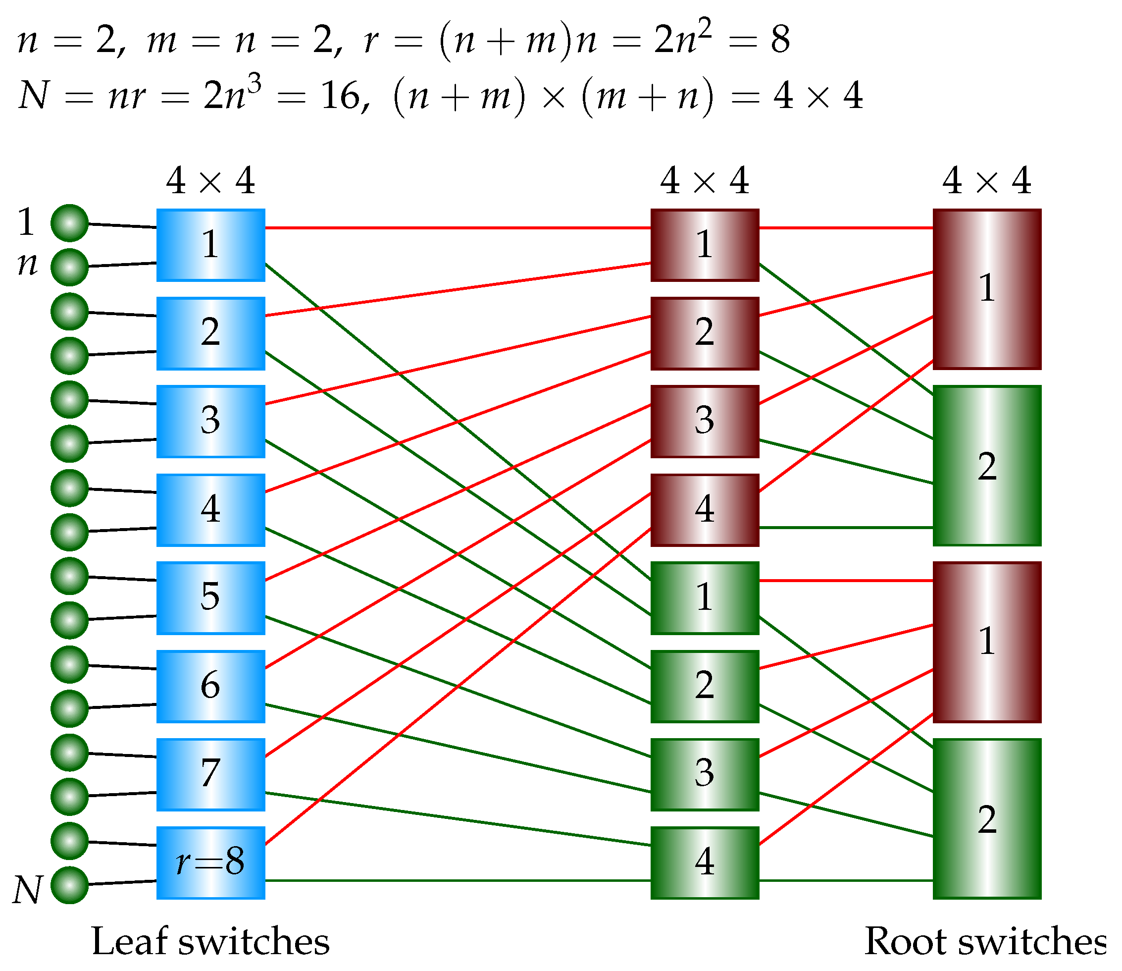
Consider a three-stage ISNBC network. Referring to
Figure 7, there are
switches in the leaf stage; there are
m building blocks, and each building block is a two-stage ISNBC network whose number of switches is
, as derived above. The total number of switches is
, and each switch is a square
crossbar. Then, the total number of crosspoints is
. The total number of compute nodes is
.
A single crossbar requires crosspoints. The crosspoint ratio of a three-stage ISNBC network relative to a single crossbar is . To guarantee that the ratio is less than 1, is needed.
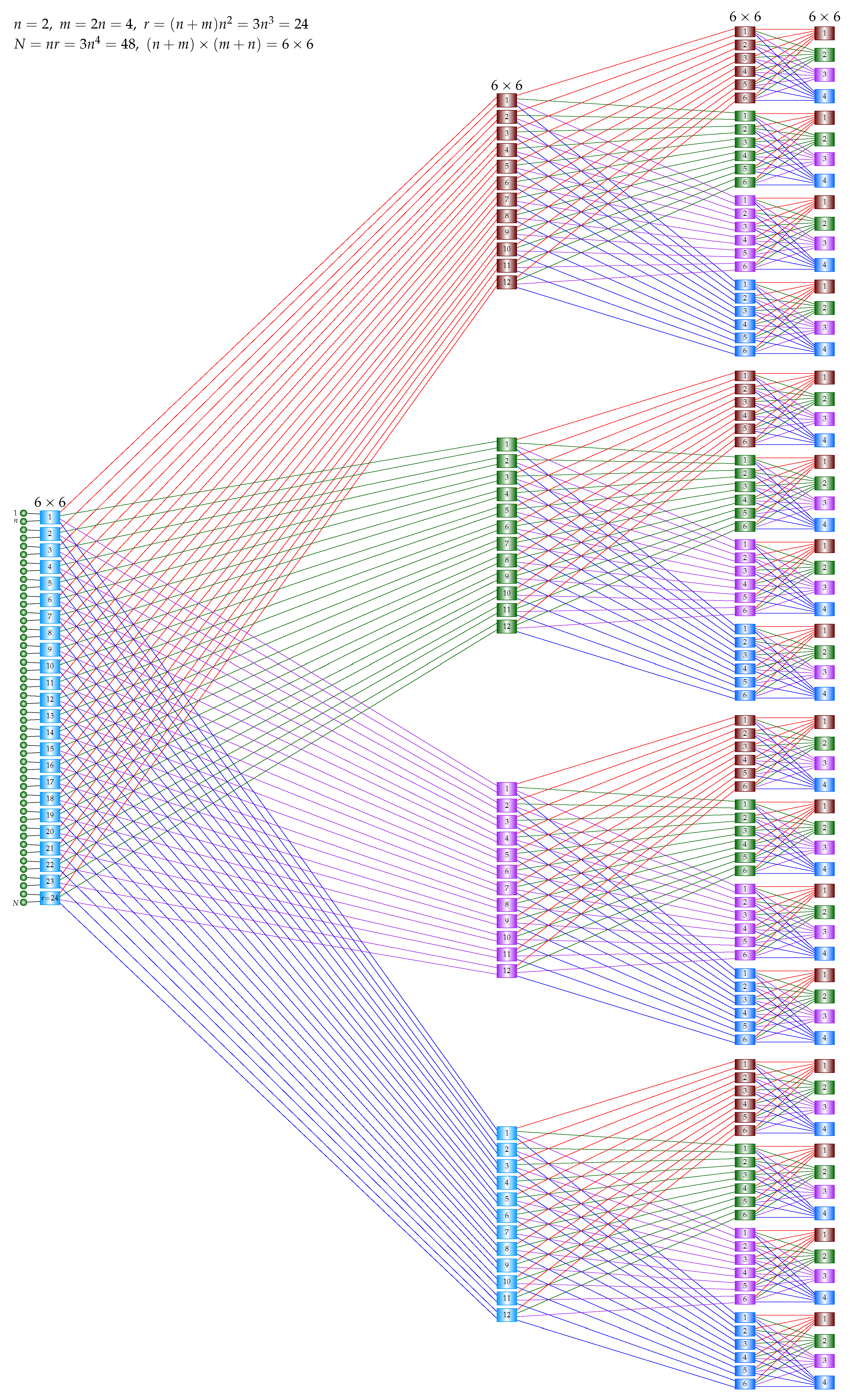
Consider a four-stage ISNBC network. Referring to
Figure 9, there are
switches in the leaf stage; there are
m building blocks, and each building block is a three-stage ISNBC network whose number of switches is
, as derived above. The total number of switches is
, and each switch is a square
crossbar. Then, the total number of crosspoints is
. The total number of compute nodes is
.
A single crossbar requires crosspoints. The crosspoint ratio of a four-stage ISNBC network relative to a single crossbar is . To guarantee that the ratio is less than 1, is needed.
Table 10 lists the crosspoints of ISNBC networks. The “Crossbar” column shows the number of crosspoints in a single crossbar. The “ISNBC” column shows the number of crosspoints in an ISNBC network. The number of crosspoints of the ISNBC network is better (smaller) than that of a single crossbar when
for the two-stage ISNBC network and
for the three- and four-stage ISNBC networks.
The number of crosspoints for a traditional strictly nonblocking folded Clos network that uses crossbars of different sizes is examined below. A two-stage traditional strictly nonblocking folded Clos network has n switches in the leaf stage and switches in the root stage. A leaf switch is an crossbar. A root switch is an crossbar. Then, the total number of crosspoints is . The total number of compute nodes is .
A single crossbar requires crosspoints. The crosspoint ratio of a two-stage traditional strictly nonblocking folded Clos network relative to a single crossbar is . To guarantee that the ratio is less than 1, is needed.
Consider the three-stage case. There are switches in the leaf stage, and each switch is an crossbar. There are building blocks, and each building block has crosspoints, as derived above. Then, the total number of crosspoints is . The total number of compute nodes is . A single crossbar requires crosspoints. The crosspoint ratio of a three-stage traditional strictly nonblocking folded Clos network relative to a single crossbar is . To guarantee that the ratio is less than 1, is needed.
Consider the four-stage case. There are switches in the leaf stage, and each switch is an crossbar. There are building blocks, and each building block has crosspoints, as derived above. Then, the total number of crosspoints is . The total number of compute nodes is . A single crossbar requires crosspoints. The crosspoint ratio of a four-stage traditional strictly nonblocking folded Clos network relative to a single crossbar is . To guarantee that the ratio is less than 1, is needed.
Table 11 summarizes the crosspoint ratio relative to a single crossbar for traditional strictly nonblocking folded Clos networks and ISNBC networks. The general formula for calculating the ISNBC crosspoint ratio relative to a single crossbar is
, where
s is the number of stages and the number of compute nodes is
.
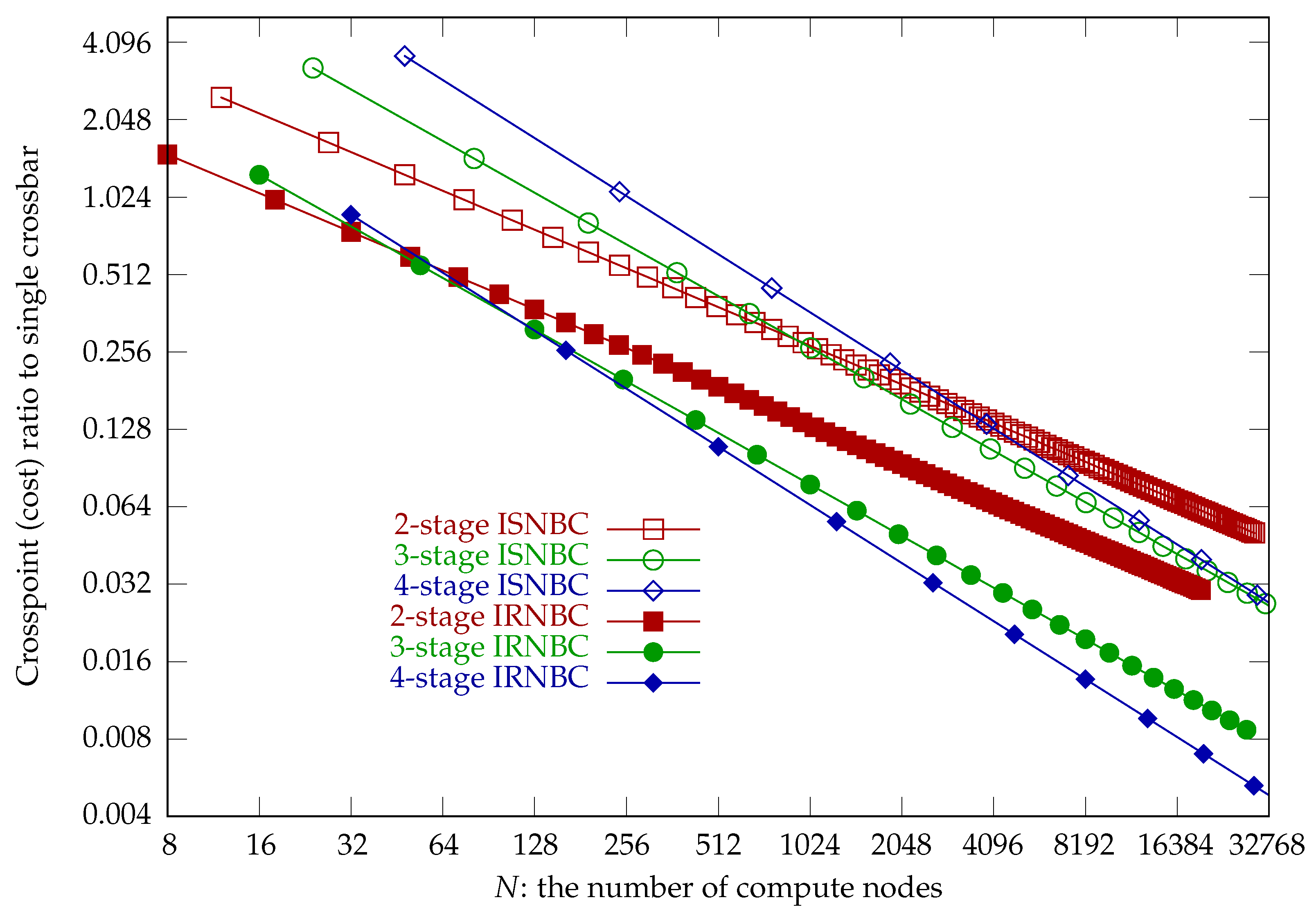
Table 12 lists the crosspoint ratios relative to a single crossbar for strictly nonblocking folded Clos networks. The ratios are calculated based on the formulas in
Table 11.
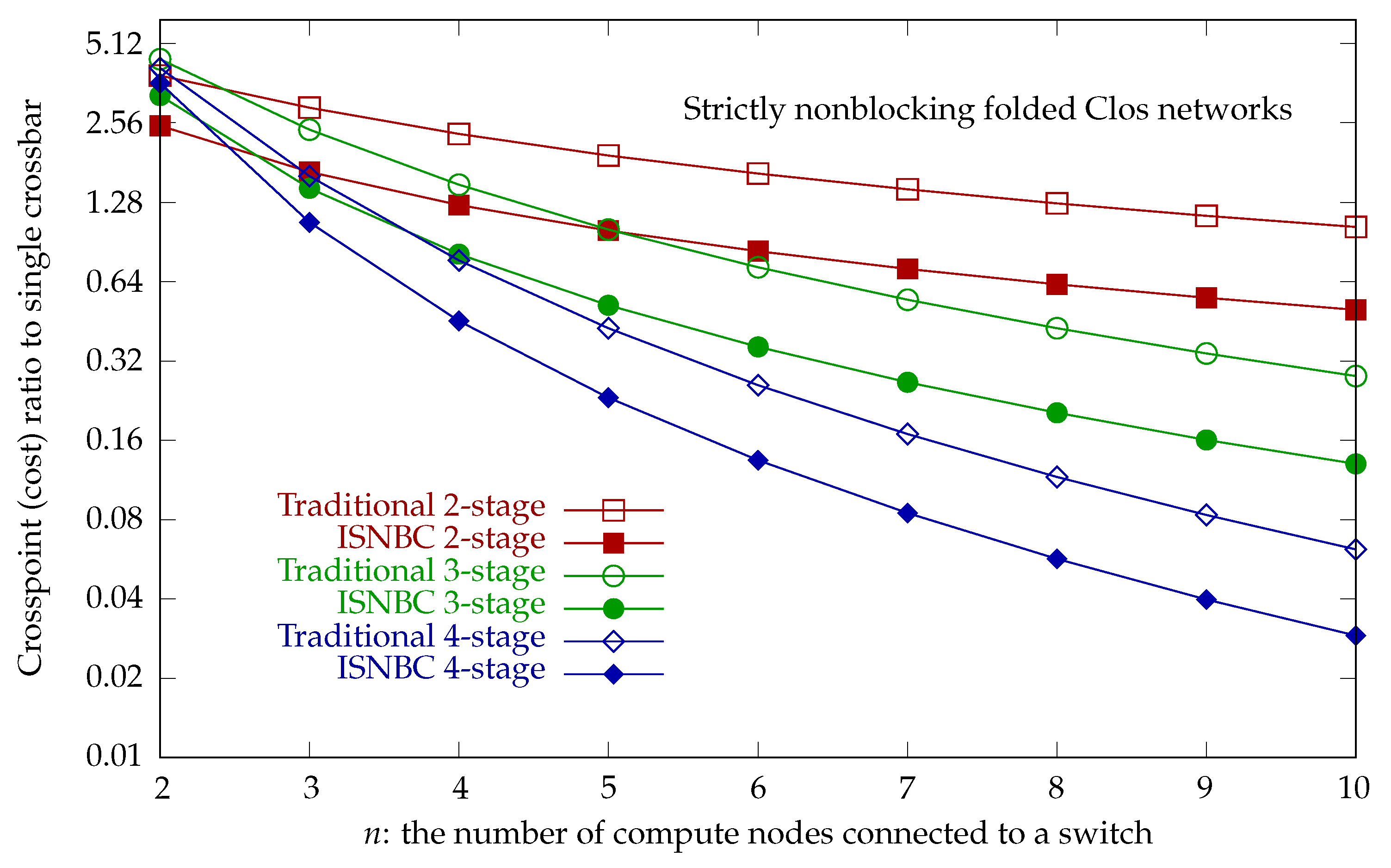
Figure 18 plots the crosspoint ratio relative to a single crossbar for strictly nonblocking folded Clos networks, showing that ISNBC networks have a lower crosspoint cost than traditional strictly nonblocking folded Clos networks. Also note that ISNBC networks use equally sized square crossbars for all switches in the network.
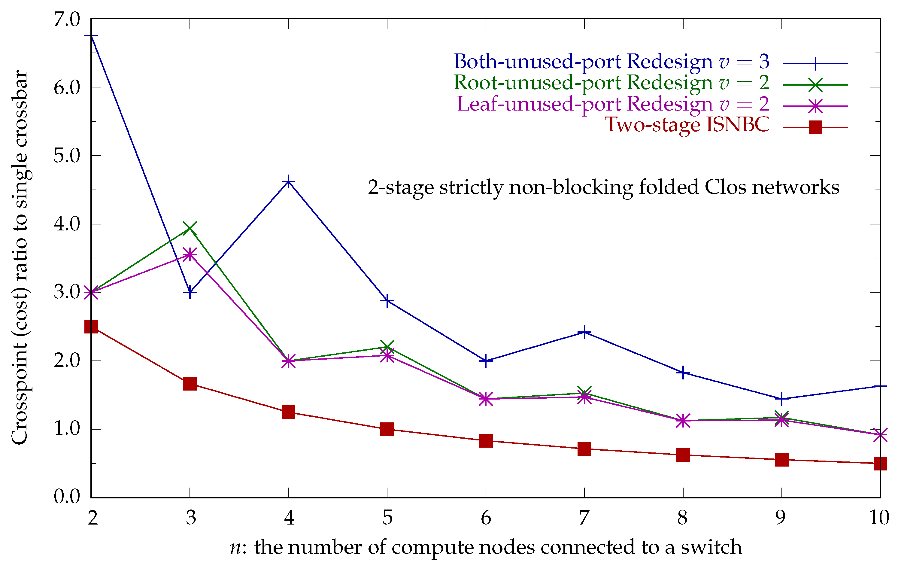
Figure 19 plots the crosspoint ratio relative to a single crossbar for strictly nonblocking folded Clos networks, showing that ISNBC networks have a lower crosspoint cost than the strictly nonblocking folded Clos network proposed in [
16]. The network proposed in [
16] is labeled “Redesign” in the figure, only supports two stages, and uses multiple links (
) between a leaf switch and a root switch. If the network is constructed using equally sized crossbar switches, there will be unused ports on the leaf switch, the root switch, or both the leaf and root switches.


