
A Self-Compensating Non-Intrusive Ring-Type AC Voltage Sensor Based on Capacitive Coupling

Abstract
1. Introduction
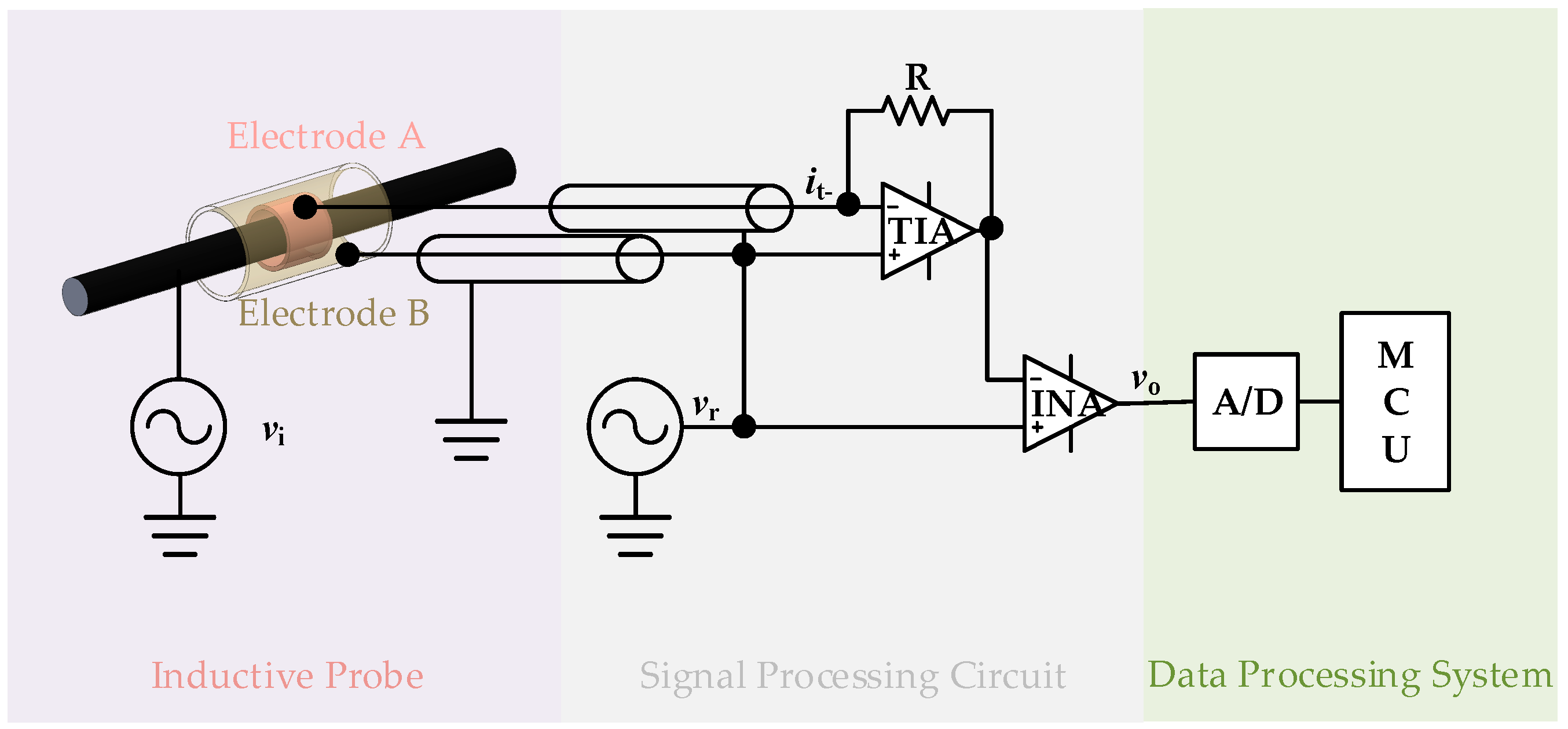
2. Sensor Design
3. Principle
3.1. Self-Compensation Principle
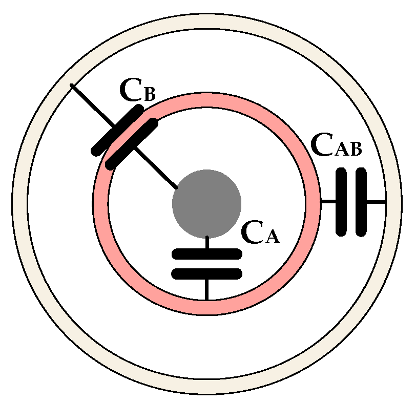
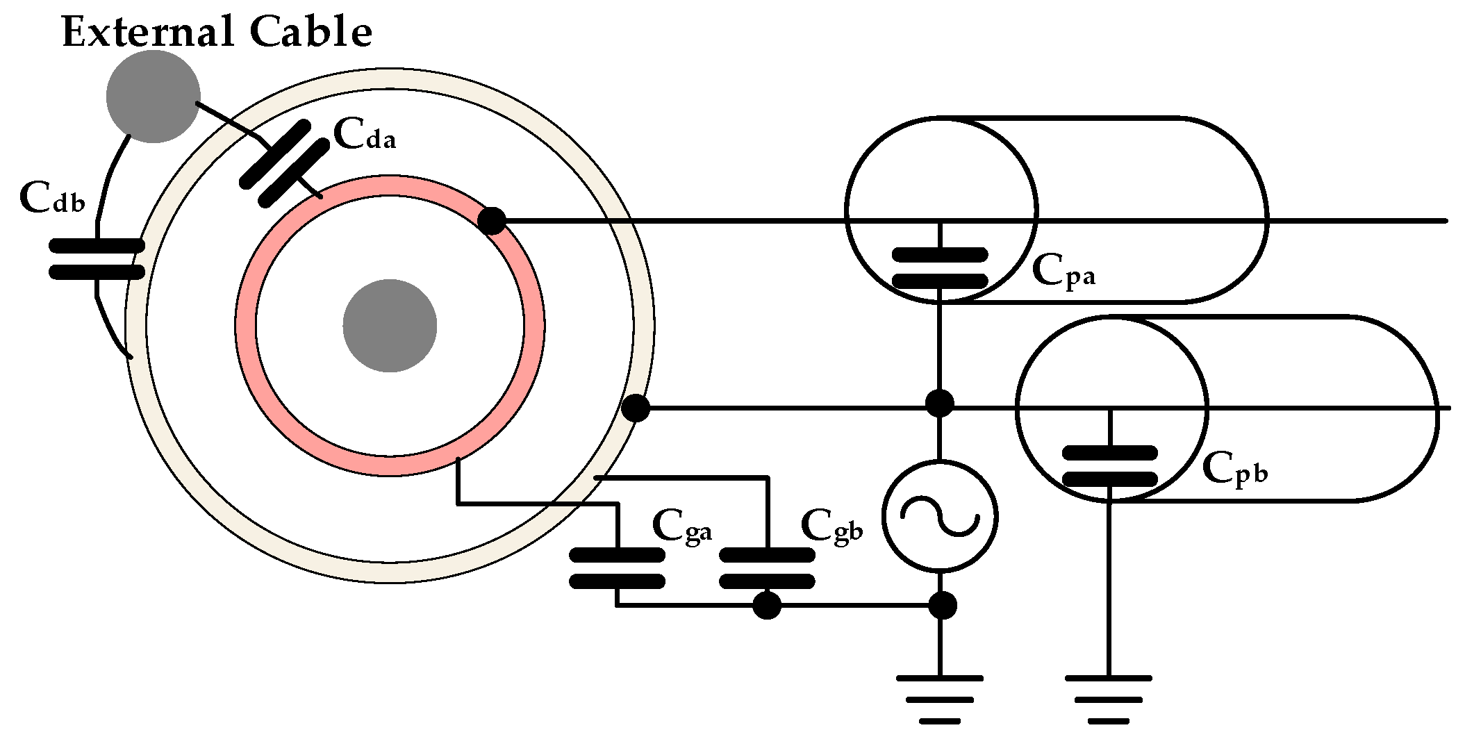
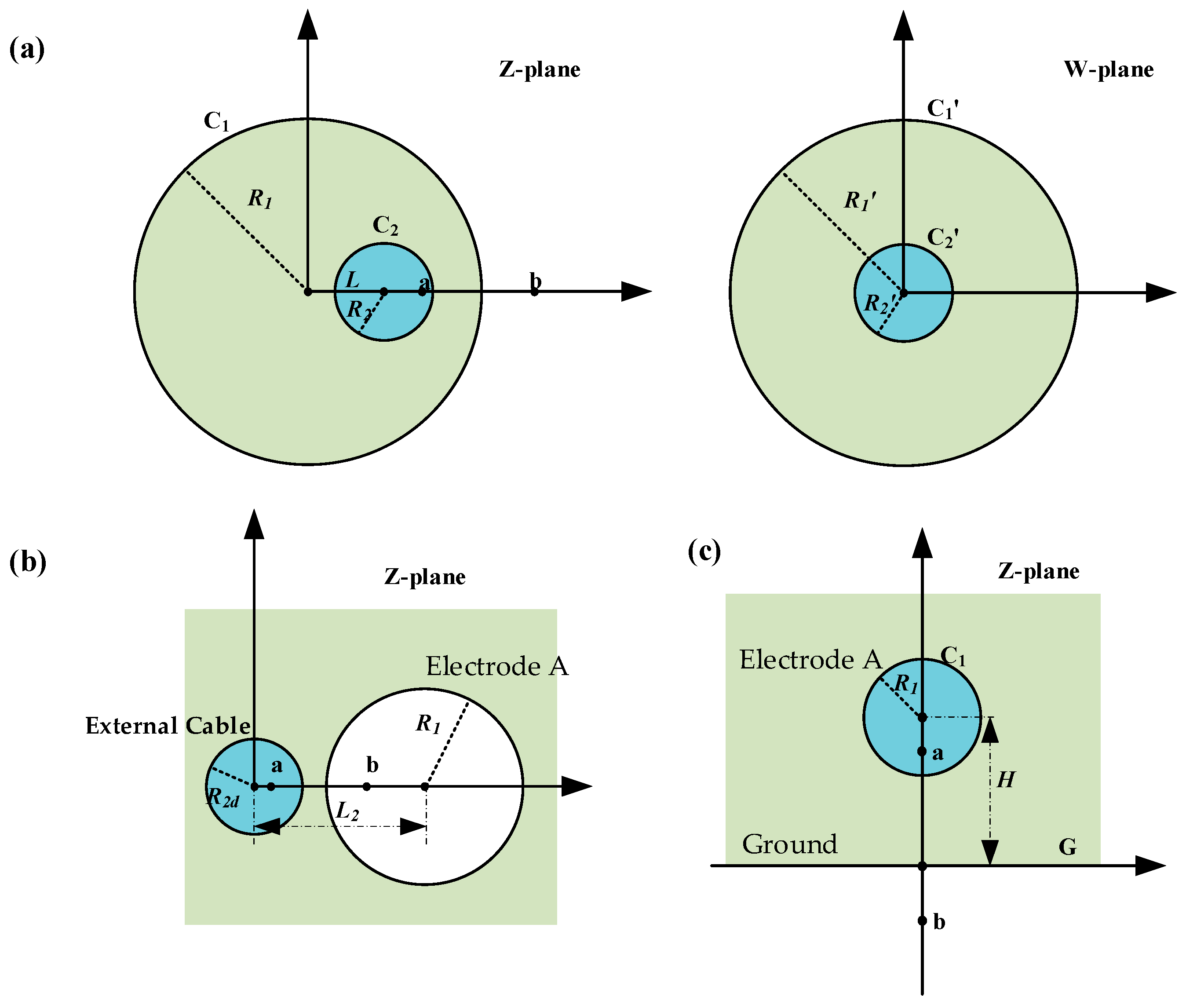
3.2. Effect of Parasitic Capacitance
4. Experimental Setup and Results
4.1. Experimental Setup
4.2. Linearity Test
4.3. Response to AC Voltage
4.4. Self-Compensation
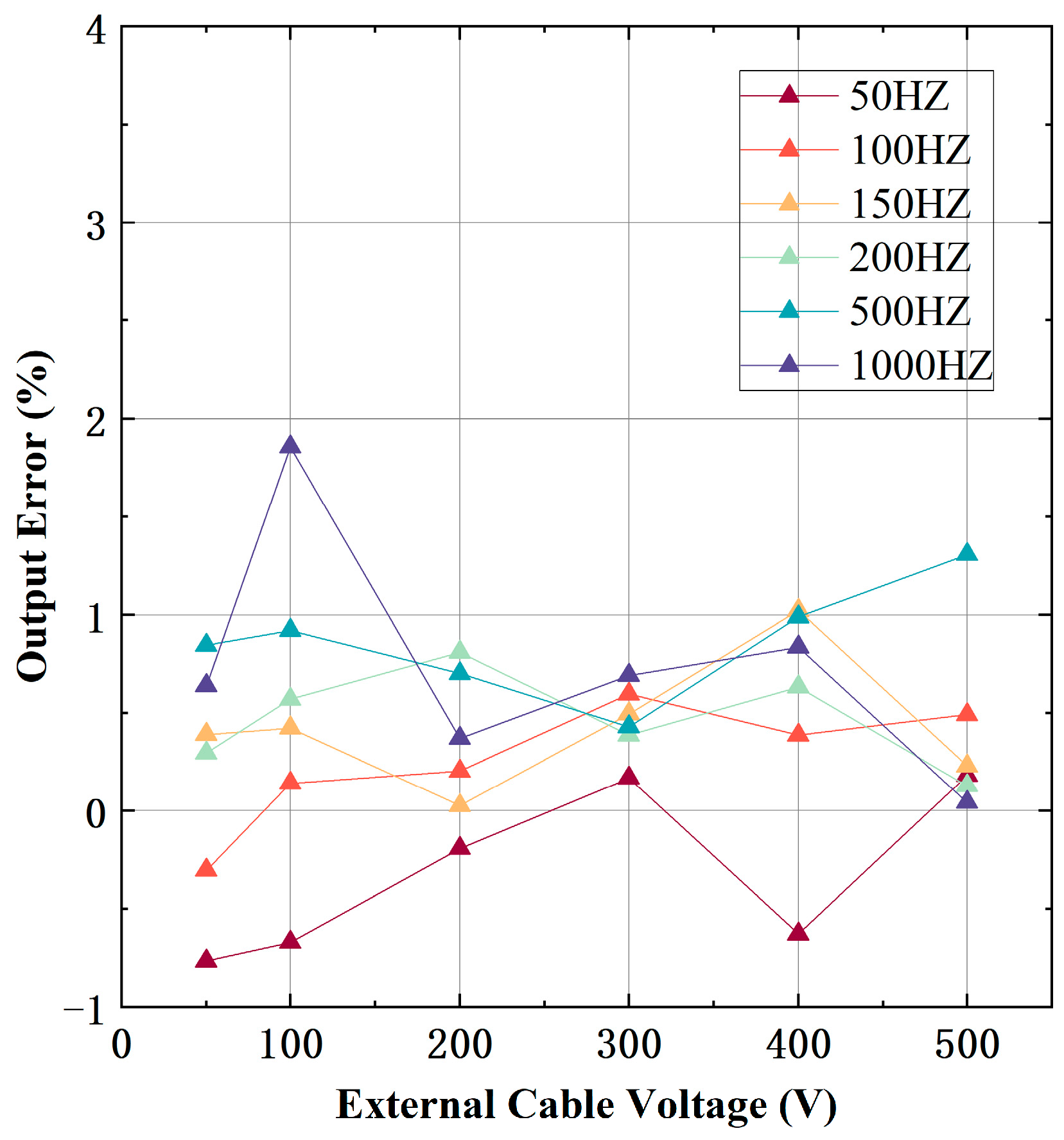
4.5. Shielding Effect
5. Conclusions
Author Contributions
Funding
Data Availability Statement
Acknowledgments
Conflicts of Interest
References
- Yang, P.; Wen, X.; Lv, Y.; Chu, Z.; Peng, C. A Non-Intrusive Voltage Measurement Scheme Based on MEMS Electric Field Sensors: Theoretical Analysis and Experimental Verification of AC Power Lines. Rev. Sci. Instrum. 2021, 92, 065002. [Google Scholar] [CrossRef] [PubMed]
- Liu, J.; Xia, S.; Peng, C.; Chu, Z.; Lei, H.; Liu, X.; Zhang, Z.; Zhang, W.; Peng, S.; Gao, Y. A Wafer-Level Vacuum Packaged MEMS Electric Field Sensor Based on SOI-SOG Bonding. Acta Electron. Sin. 2023, 51, 2517–2525. [Google Scholar] [CrossRef]
- Mohanty, R.; Pradhan, A.K.; Dutta, P.K. Accurate Voltage Phasor Measurement for Electric Power Transmission Line Protection Using Current Sensor. IEEE Sens. Lett. 2024, 8, 7001004. [Google Scholar] [CrossRef]
- Krause, T.C.; Camenzind, K.; Green, D.H.; Moeller, A.; Huchel, L.; Leeb, S.B. A Sensor Topology for Noncontact AC Voltage Measurement of Polyphase Cables. IEEE Trans. Instrum. Meas. 2022, 71, 1500110. [Google Scholar] [CrossRef]
- Sun, S.; Ma, F.; Yang, Q.; Ni, H.; Bai, T.; Ke, K.; Qiu, Z. Research on Non-Contact Voltage Measurement Method Based on Near-End Electric Field Inversion. Energies 2023, 16, 6468. [Google Scholar] [CrossRef]
- Xing, Y.; Liu, J.; Li, F.; Zhang, G.; Li, J. Advanced Dual-Probes Noncontact Voltage Measurement Approach for AC/DC Power Transmission Wire Based on the Electric Field Radiation Principle. IEEE Trans. Instrum. Meas. 2023, 72, 1503511. [Google Scholar] [CrossRef]
- Haberman, M.A.; Spinelli, E.M. A Noncontact Voltage Measurement System for Power-Line Voltage Waveforms. IEEE Trans. Instrum. Meas. 2020, 69, 2790–2797. [Google Scholar] [CrossRef]
- Wang, H.; Zeng, R.; Zhuang, C.; Lyu, G.; Yu, J.; Niu, B.; Li, C. Measuring AC/DC Hybrid Electric Field Using an Integrated Optical Electric Field Sensor. Electr. Power Syst. Res. 2020, 179, 106087. [Google Scholar] [CrossRef]
- Wu, Q.; Zhang, X.C. Ultrafast Electrooptic Field Sensors. Appl. Phys. Lett. 1996, 68, 1604–1606. [Google Scholar] [CrossRef]
- Zeng, R. Study of an Integrated Optical Sensor with Mono-Shielding Electrode for Intense Transient E-Field Measurement. Measurement 2014, 50, 356–362. [Google Scholar] [CrossRef]
- Shenil, P.S.; George, B. An Auto-Balancing Scheme for Non-Contact AC Voltage Measurement. In Proceedings of the 2018 IEEE 9th International Workshop on Applied Measurements for Power Systems (AMPS), Bologna, Italy, 26–28 September 2018; pp. 1–5. [Google Scholar]
- Shenil, P.S.; Arjun, R.; George, B. Feasibility Study of a Non-Contact AC Voltage Measurement System. In Proceedings of the 2015 IEEE International Instrumentation and Measurement Technology Conference (I2MTC) Proceedings, Pisa, Italy, 11–14 May 2015; pp. 399–404. [Google Scholar]
- Haberman, M.A.; Spinelli, E.M. Noncontact AC Voltage Measurements: Error and Noise Analysis. IEEE Trans. Instrum. Meas. 2018, 67, 1946–1953. [Google Scholar] [CrossRef]
- Martins, A.V.; Bacurau, R.M.; Dos Santos, A.D.; Ferreira, E.C. Nonintrusive Energy Meter for Nontechnical Losses Identification. IEEE Trans. Instrum. Meas. 2020, 69, 1140–1147. [Google Scholar] [CrossRef]
- Gorla, D.P.M.; Janus, P.; Edin, H. Non-Contact Voltage Measurement Technique for On-Line Monitoring of Transient Overvoltages. In Proceedings of the Nordic Insulation Symposium, Trondheim, Norway, 13–15 June 2022. [Google Scholar] [CrossRef]
- Pouryazdan, A.; Costa, J.C.; Prance, R.J.; Prance, H.; Munzenrieder, N. Non-Contact Long Range AC Voltage Measurement. In Proceedings of the 2019 IEEE SENSORS, Montreal, QC, Canada, 27–30 October 2019; pp. 1–4. [Google Scholar]
- Suo, C.; Huang, R.; Zhou, G.; Zhang, W.; Wang, Y.; He, M. Self-Calibration Sensor for Contactless Voltage Measurement Based on Dynamic Capacitance. Sensors 2023, 23, 3851. [Google Scholar] [CrossRef] [PubMed]
- Suo, C.; He, M.; Zhou, G.; Shi, X.; Tan, X.; Zhang, W. Research on Non-Invasive Floating Ground Voltage Measurement and Calibration Method. Electronics 2023, 12, 1858. [Google Scholar] [CrossRef]
- Si, D.; Wang, J.; Wei, G.; Yan, X. Method and Experimental Study of Voltage Measurement Based on Electric Field Integral With Gauss–Legendre Algorithm. IEEE Trans. Instrum. Meas. 2020, 69, 2771–2778. [Google Scholar] [CrossRef]
- Jakubowski, J.; Kuchta, M.; Kubacki, R. D-Dot Sensor Response Improvement in the Evaluation of High-Power Microwave Pulses. Electronics 2021, 10, 123. [Google Scholar] [CrossRef]
- Shenil, P.S.; George, B. Development of a Nonintrusive True-RMS AC Voltage Measurement Probe. IEEE Trans. Instrum. Meas. 2019, 68, 3899–3906. [Google Scholar] [CrossRef]
- Palmer, H.B. The Capacitance of a Parallel-Plate Capacitor by the Schwartz-Christoffel Transformation. Trans. Am. Inst. Electr. Eng. 1937, 56, 363–366. [Google Scholar] [CrossRef]
- Cohn, S.B. Problems in Strip Transmission Lines. IEEE Trans. Microw. Theory Techn. 1955, 3, 119–126. [Google Scholar] [CrossRef]
- Yang, P.; Wen, X.; Chu, Z.; Ni, X.; Peng, C. Non-Intrusive DC Voltage Measurement Based on Resonant Electric Field Microsensors. J. Micromech. Microeng. 2021, 31, 064001. [Google Scholar] [CrossRef]


| Symbols | Value | Symbols | Value |
|---|---|---|---|
| 10 mm | 50 mm | ||
| 2 mm | 2 mm | ||
| 0 mm | 1000 mm |
| Cable Diameter (mm) | Measured Voltage Without Self-Compensation (V) | Relative Deviation (%) | Measured Voltage with Self-Compensation (V) | Relative Deviation (%) |
|---|---|---|---|---|
| 1.5 | 267 | 14.60 | 248 | 6.44 |
| 2 | 196 | 15.64 | 246 | 5.58 |
| 3 | 284 | 21.83 | 234 | 0.43 |
| 4 | 265 | 13.87 | 235 | 0.86 |
| 9 | 294 | 26.21 | 221 | 5.15 |
| Cable Position Offset (mm) | Measured Voltage with Self-Compensation (V) | Relative Deviation (%) |
|---|---|---|
| 0 | 221 | 5.15 |
| 2 | 228 | 1.94 |
| 4 | 237 | 1.83 |
| 6 | 222 | 4.50 |
Disclaimer/Publisher’s Note: The statements, opinions and data contained in all publications are solely those of the individual author(s) and contributor(s) and not of MDPI and/or the editor(s). MDPI and/or the editor(s) disclaim responsibility for any injury to people or property resulting from any ideas, methods, instructions or products referred to in the content. |
© 2024 by the authors. Licensee MDPI, Basel, Switzerland. This article is an open access article distributed under the terms and conditions of the Creative Commons Attribution (CC BY) license (https://creativecommons.org/licenses/by/4.0/).
Share and Cite
Wang, J.; Li, J.; Peng, C.; Wu, Z.; Ju, D.; Zhang, Q. A Self-Compensating Non-Intrusive Ring-Type AC Voltage Sensor Based on Capacitive Coupling. Micromachines 2024, 15, 1314. https://doi.org/10.3390/mi15111314
Wang J, Li J, Peng C, Wu Z, Ju D, Zhang Q. A Self-Compensating Non-Intrusive Ring-Type AC Voltage Sensor Based on Capacitive Coupling. Micromachines. 2024; 15(11):1314. https://doi.org/10.3390/mi15111314
Chicago/Turabian StyleWang, Junpeng, Jiacheng Li, Chunrong Peng, Zhengwei Wu, Dengfeng Ju, and Qiang Zhang. 2024. "A Self-Compensating Non-Intrusive Ring-Type AC Voltage Sensor Based on Capacitive Coupling" Micromachines 15, no. 11: 1314. https://doi.org/10.3390/mi15111314
APA StyleWang, J., Li, J., Peng, C., Wu, Z., Ju, D., & Zhang, Q. (2024). A Self-Compensating Non-Intrusive Ring-Type AC Voltage Sensor Based on Capacitive Coupling. Micromachines, 15(11), 1314. https://doi.org/10.3390/mi15111314