
Design, Analysis and Experiment of a Bridge-Type Piezoelectric Actuator for Infrared Image Stabilization


Abstract
1. Introduction
2. Design of the Actuator
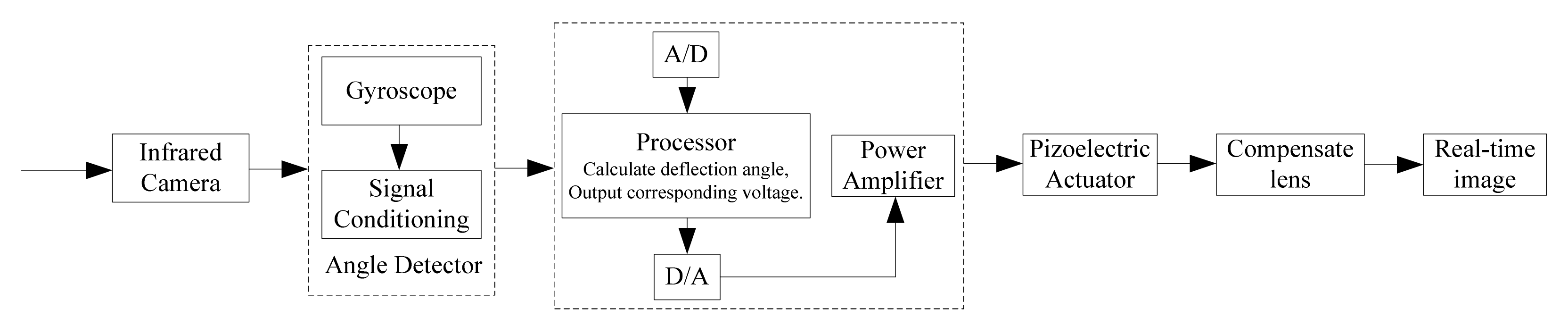
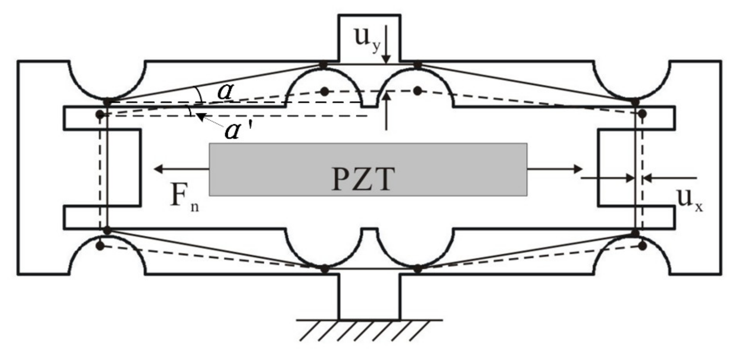
2.1. Design Concepts and Principles
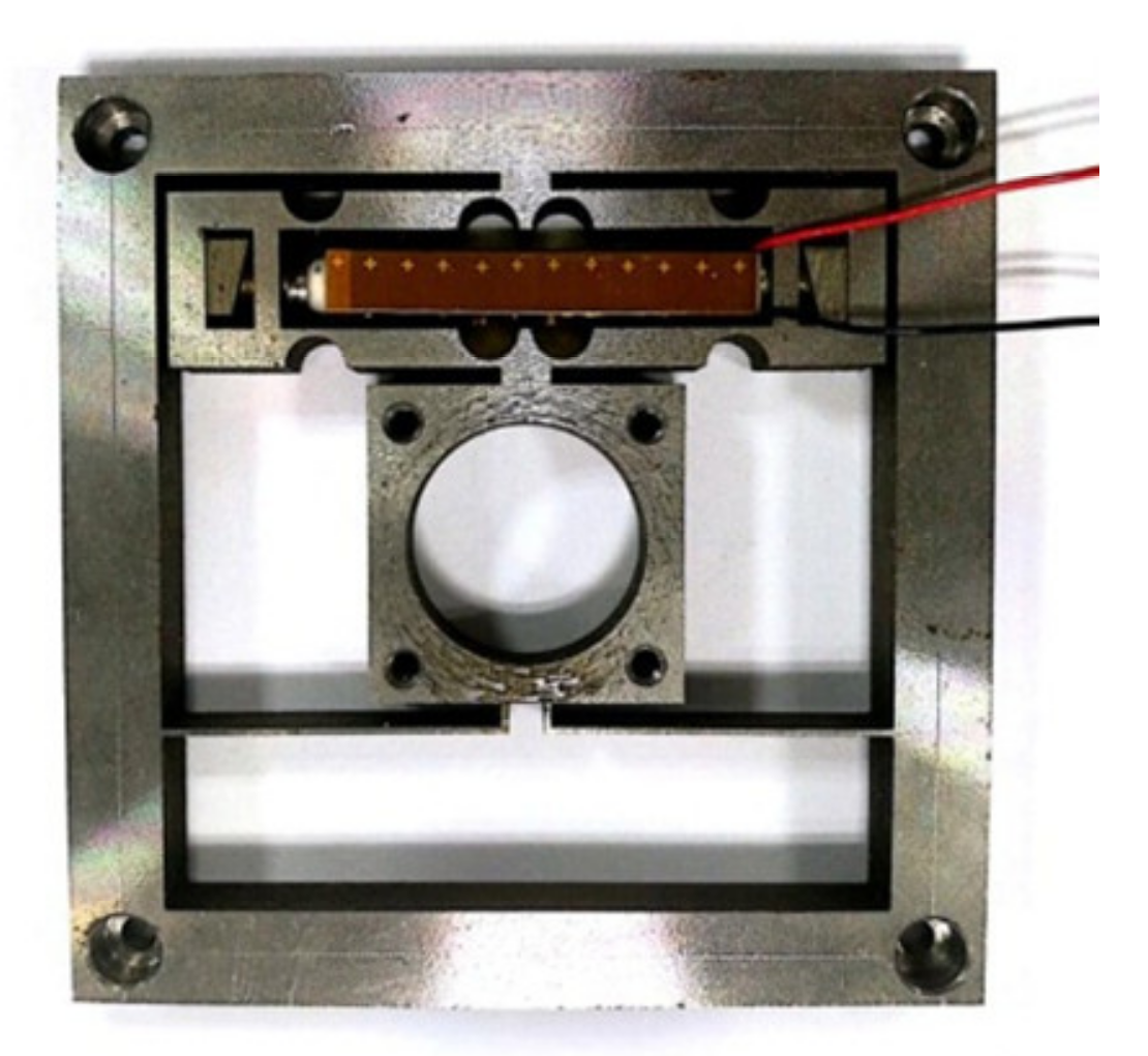
2.2. Design of the Piezoelectric Actuator
2.3. Optimization Design
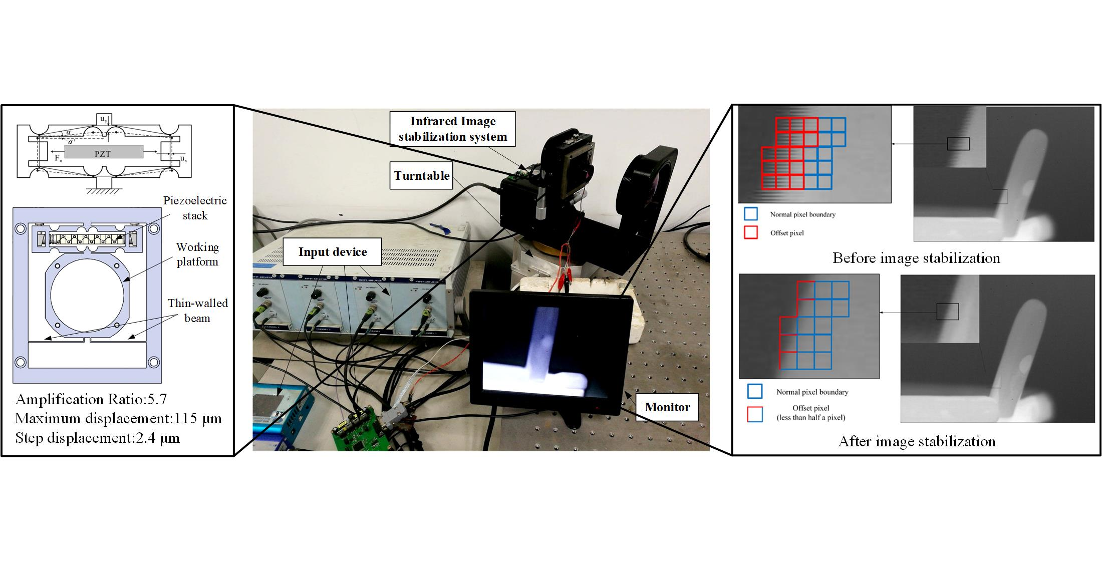
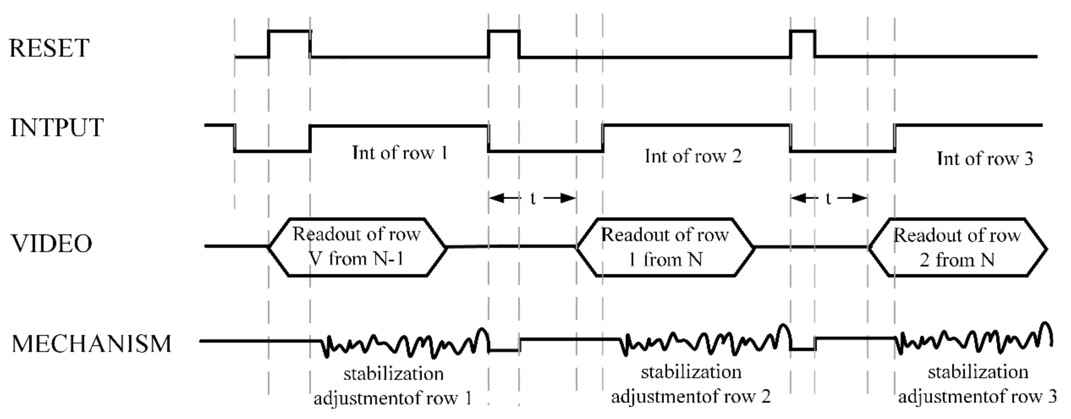
2.4. Image Stabilization Strategy and Calculation
2.5. Design of the Stabilizing Structure
3. Analysis of Experimental Results
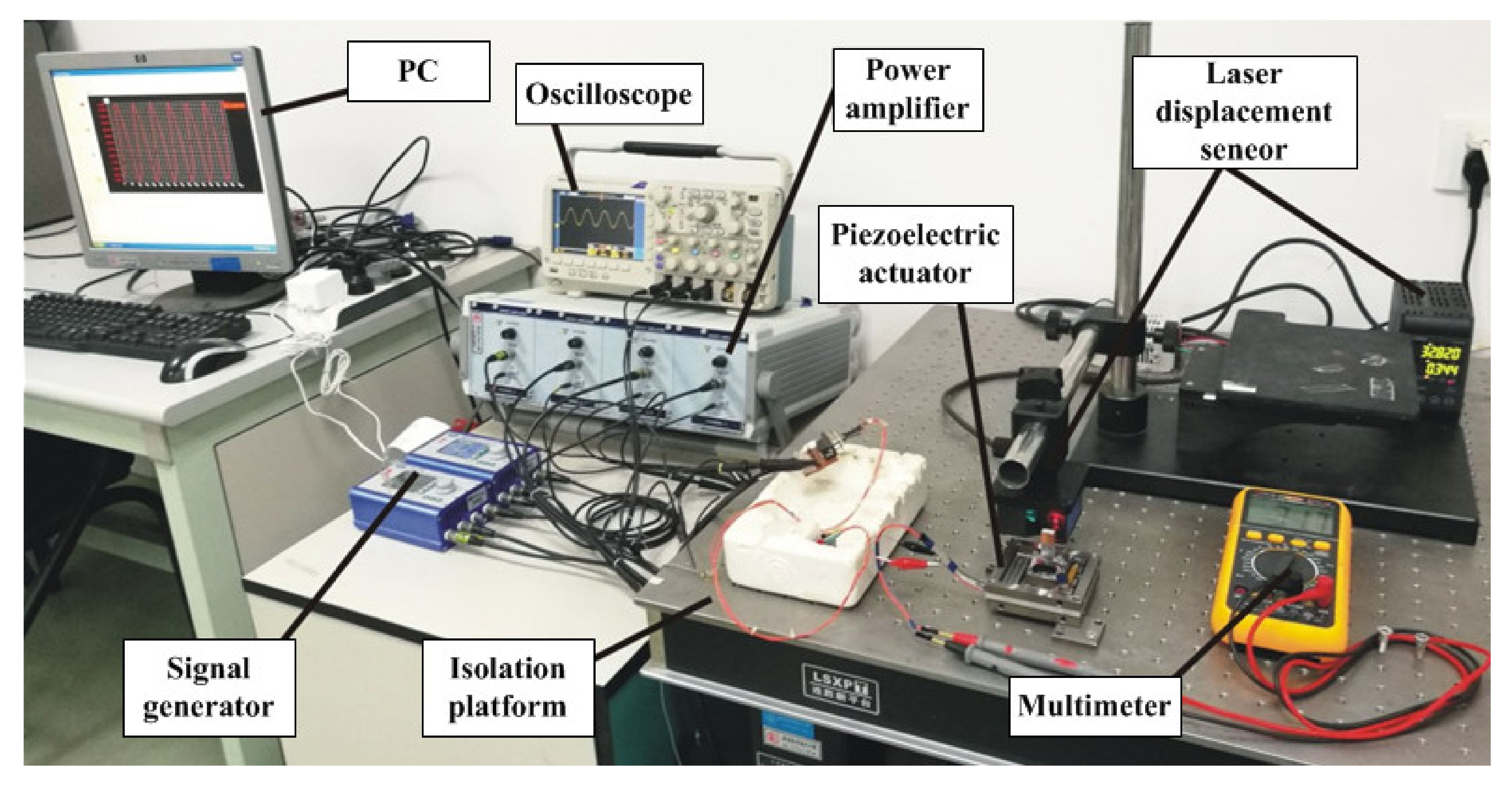
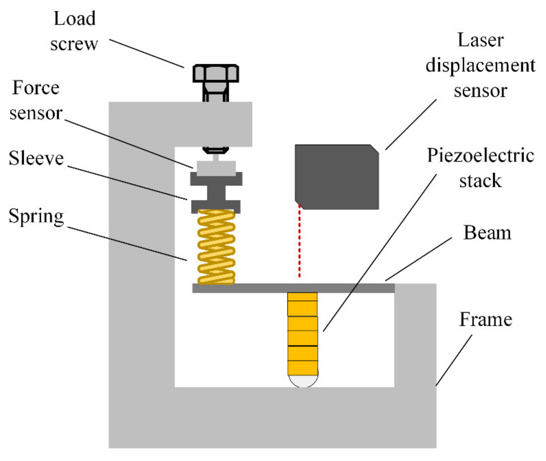
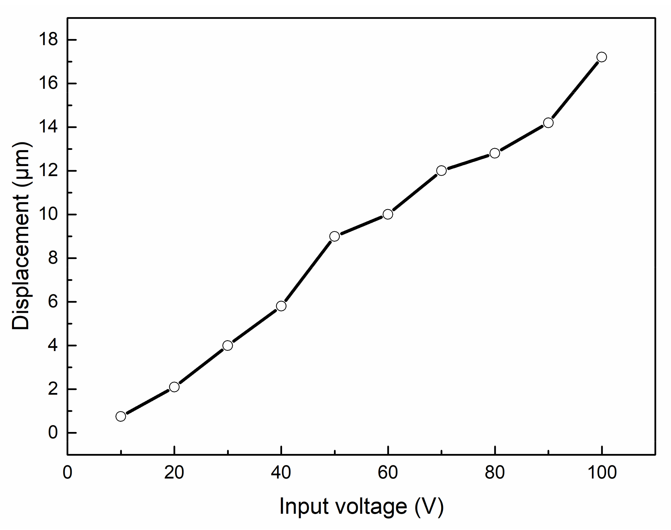
3.1. Displacement Measurement of Piezoelectric Ceramics
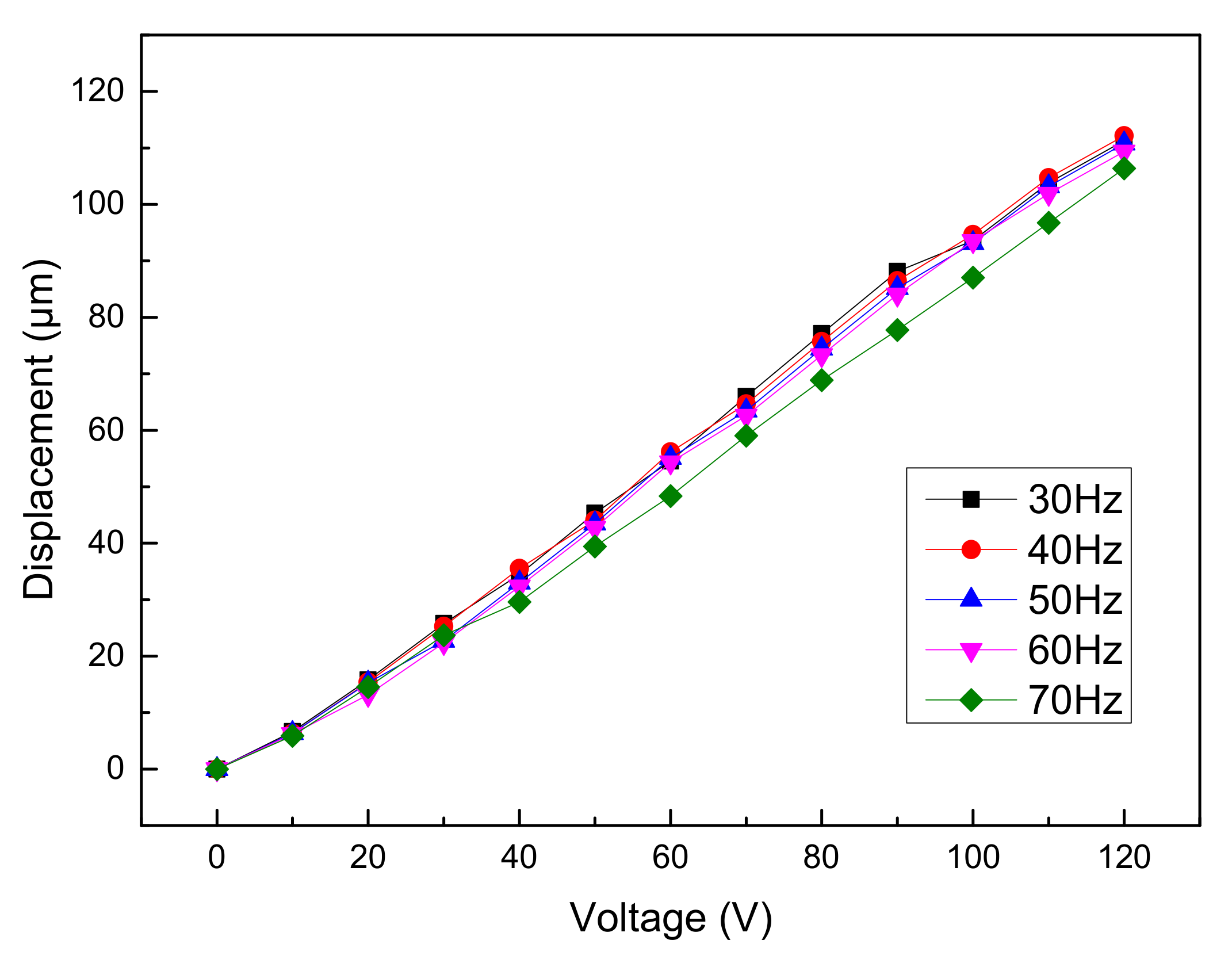
3.2. Displacement Test of the Actuator
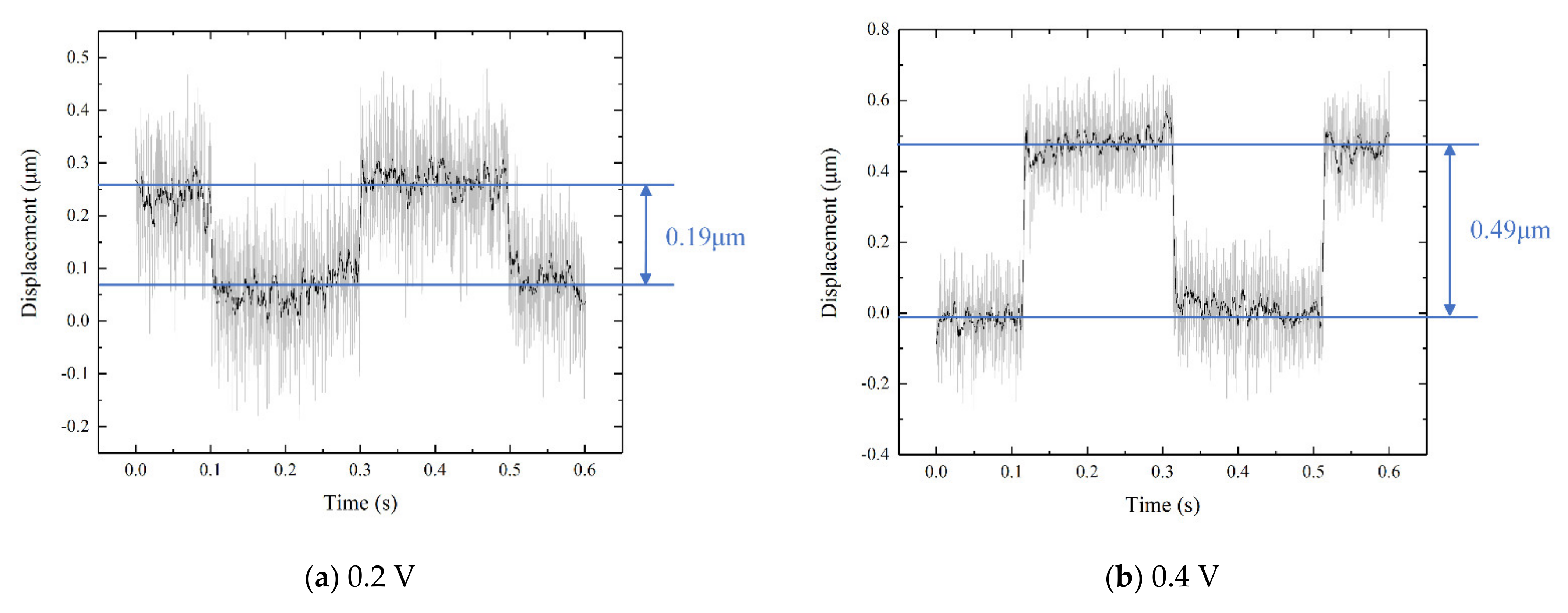
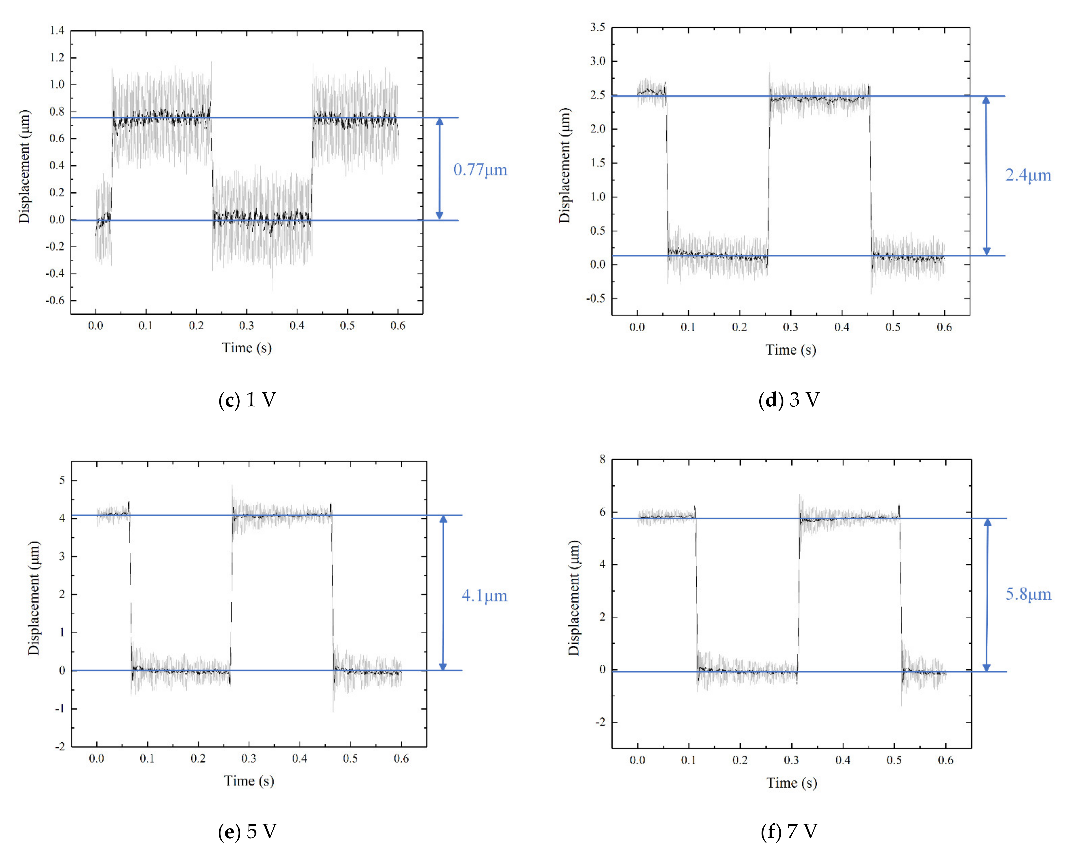
3.3. Transient Performance Test
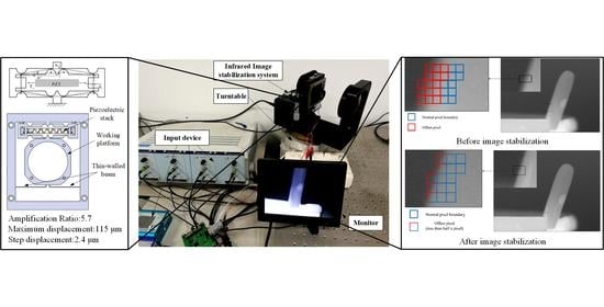
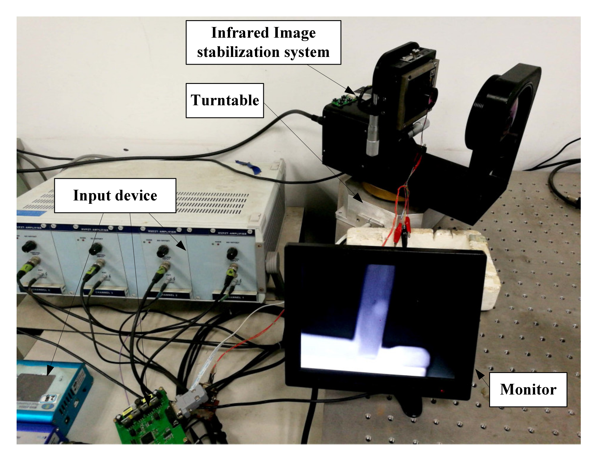
3.4. Image Stabilization Test
4. Conclusions
- (1)
- As revealed by the displacement tests, the actuator has a good linearity between the displacement and the different voltage. The maximum output displacement is 115 μm with a voltage of 120 V, and the minimum displacement is 8 μm with a voltage of 10 V. Combined with the test results of laminated piezoelectric ceramics, the amplification ratio of the mechanism is calculated as 5.7.
- (2)
- As shown by the transient performance test on the actuator, when the input voltage increased to 3 V, 5 V, and 7 V, the stepping displacements of the mechanism were 2.4 μm, 4.1 μm, and 5.8 μm, respectively, and the noise of the single-step micro-motion was relatively small, so the motion adjustment with a precision of 10 μm can be achieved without filtering modulation.
- (3)
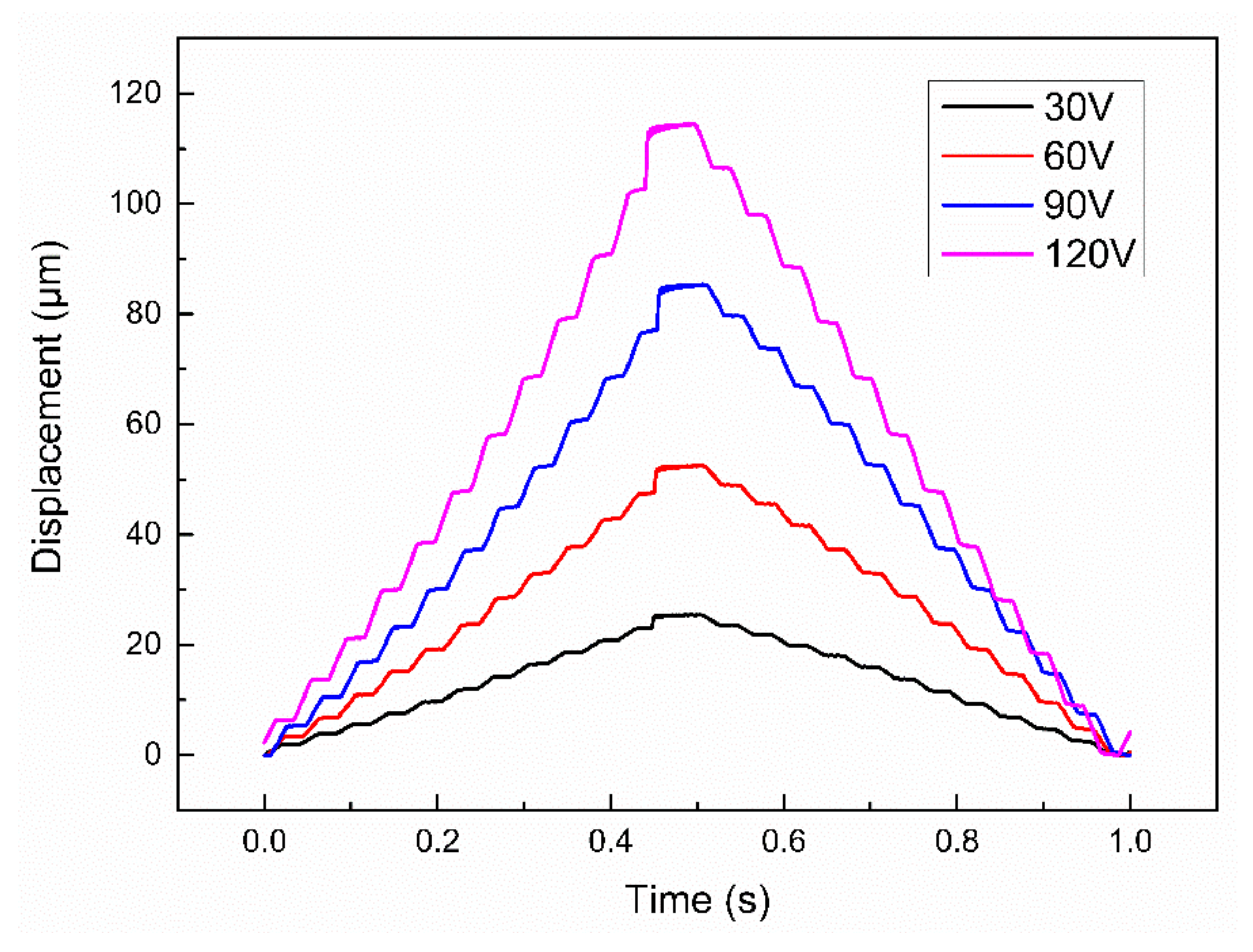
- The displacement curves under the up and down step wave indicate that when the voltage of the step wave increases, the actuator stroke increases from 20 to 115 μm, and the step distance increases from 2.4 to 11 μm. It is found that the up and down step distance of the actuator has a slight difference, but their errors are within the 10 μm displacement corresponding to one pixel, which has little impact on the image stabilization adjustment.
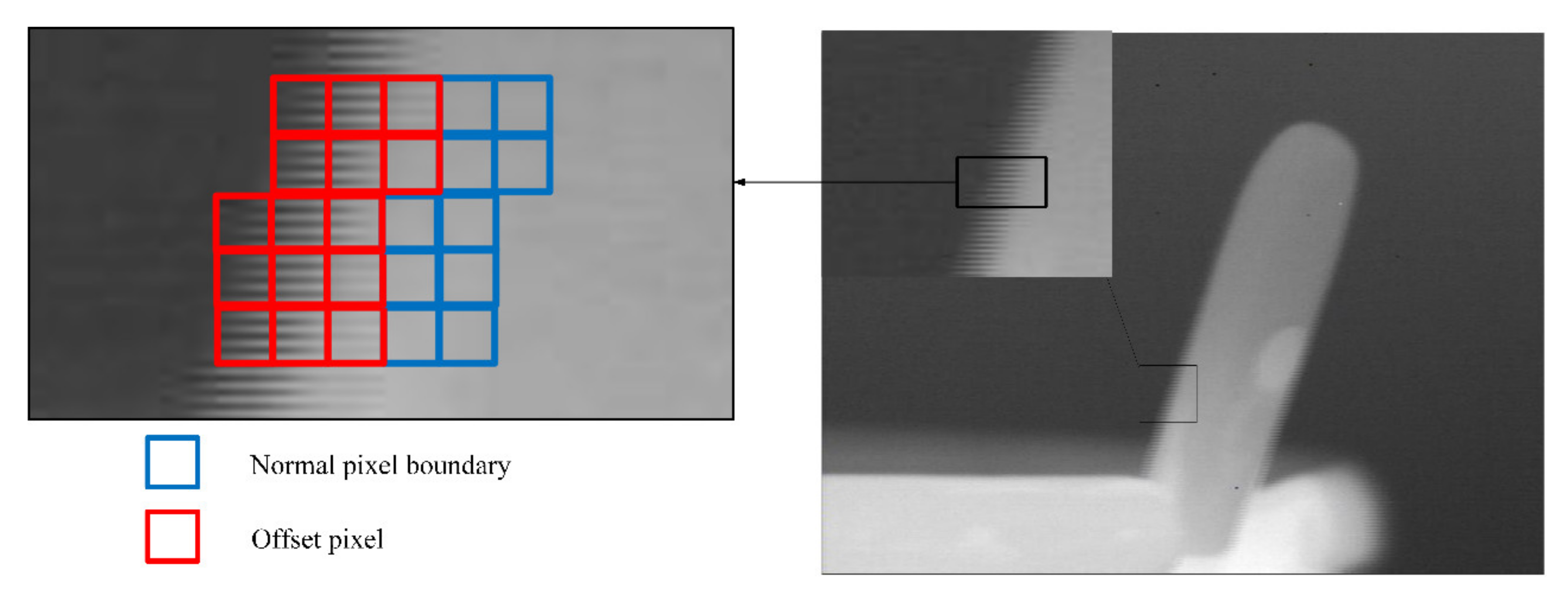
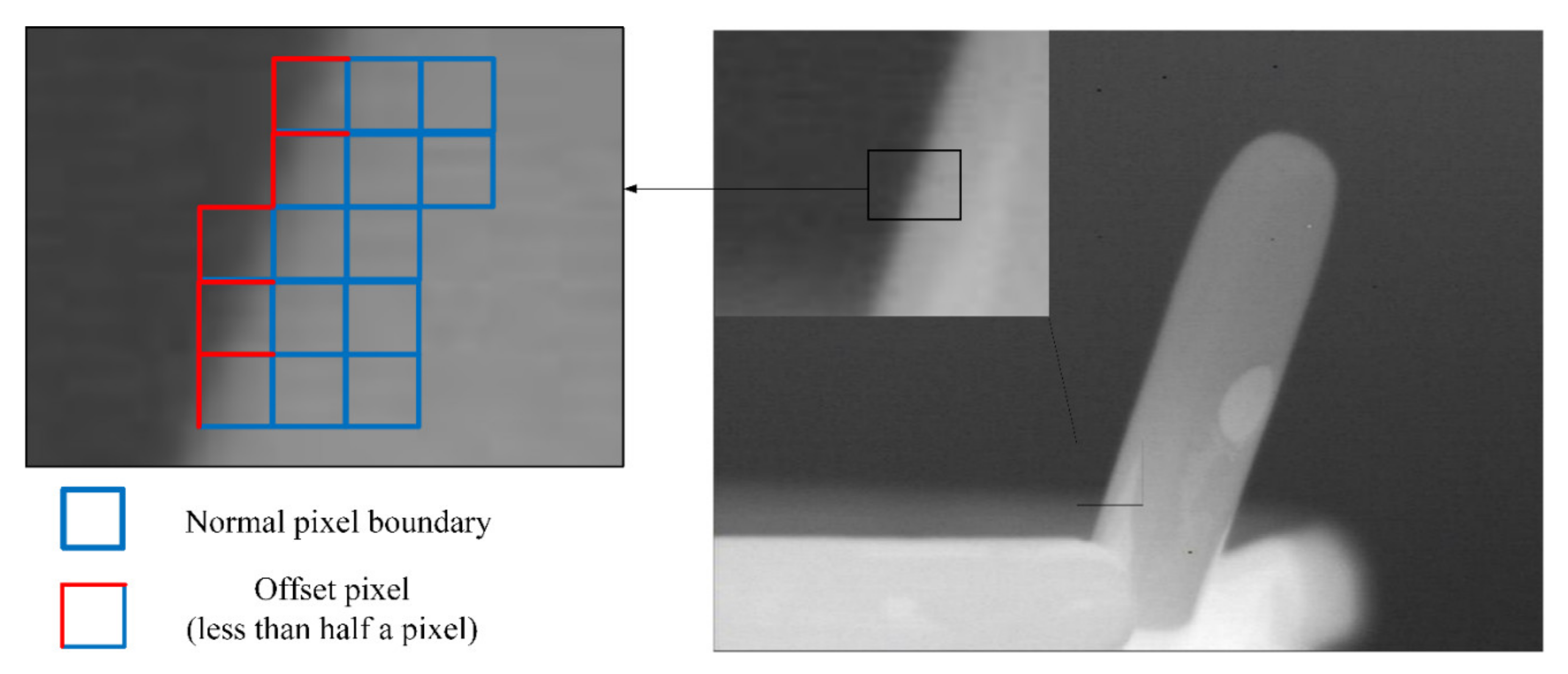
- (4)
- It can be seen from the image stabilization test, after the introduction of the image stabilization system, the imaging offset of the imaging system in the fluctuation is reduced by several pixels, thus verifying the feasibility of the image stabilization system of the piezoelectric actuator.
Author Contributions
Funding
Conflicts of Interest
References
- Zhang, C.; Marty, J.; Maynadier, A.; Chaudet, P.; Réthoré, J.; Baietto, M.C. An innovative technique for real-time adjusting exposure time of silicon-based camera to get stable gray level images with temperature evolution. Mech. Syst. Signal. Pr. 2019, 122, 419–432. [Google Scholar] [CrossRef]
- Liu, C.; Sui, X.; Liu, Y.; Kuang, X.; Gu, G.; Chen, Q. FPN estimation based nonuniformity correction for infrared imaging system. Infrared Phys. Technol. 2018, 96, 22–29. [Google Scholar] [CrossRef]
- Tong, Q.; Jiang, Y.; Wang, H.; Guo, L. Image reconstruction of dynamic infrared single-pixel imaging system. Opt. Commun. 2018, 410, 35–39. [Google Scholar] [CrossRef]
- Verma, M.; Lafarga, V.; Baron, M.; Collette, C. Active stabilization of unmanned aerial vehicle imaging platform. J. Vib. Control. 2020, 26, 1791–1803. [Google Scholar] [CrossRef]
- Hardcastle, B.; Krapp, H.G. Evolution of Biological Image Stabilization. Curr. Biol. 2016, 26, R1010–R1021. [Google Scholar] [CrossRef]
- Ko, J.; Yoon, W.J.; Kim, Y.S. A study on surgical robot image stabilization. Multimedia Tools Appl. 2017, 77, 9871–9883. [Google Scholar] [CrossRef]
- Rodriguez-Padilla, I.; Castelle, B.; Marieu, V.; Morichon, D. A Simple and Efficient Image Stabilization Method for Coastal Monitoring Video Systems. Remote Sens. 2019, 12, 70. [Google Scholar] [CrossRef]
- Yan, F.; Iliyasu, A.M.; Yang, H.; Hirota, K. Strategy for quantum image stabilization. Sci. China Inf. Sci. 2016, 59, 1–10. [Google Scholar] [CrossRef][Green Version]
- Huszka, G.; Gijs, M.A. Super-resolution optical imaging: A comparison. Micro Nano Eng. 2018, 2, 7–28. [Google Scholar] [CrossRef]
- Heya, A.; Hirata, K. Experimental Verification of Three-Degree-of-Freedom Electromagnetic Actuator for Image Stabilization. Sensors 2020, 20, 2485. [Google Scholar] [CrossRef]
- Hashimoto, M.; Kuno, T.; Sugiura, H. A New Image-Stabilizing Method by Transferring Electric Charges. IEEE Trans. Consum. Electr. 2007, 53, 1230–1236. [Google Scholar] [CrossRef]
- Cheng, S.; Liu, R.; Fan, X.; Luo, Z. Designing a stable feedback control system for blind image deconvolution. Neural Netw. 2018, 101, 101–112. [Google Scholar] [CrossRef] [PubMed]
- Hu, F.; Ma, J.; Shen, L.; Du, H. Digital video stabilization based on multilayer gray projection. Signal Process. Image Commun. 2018, 68, 42–57. [Google Scholar] [CrossRef]
- Hao, Q.; Cheng, X.; Kang, J.; Jiang, Y. An Image Stabilization Optical System Using Deformable Freeform Mirrors. Sensors 2015, 15, 1736–1749. [Google Scholar] [CrossRef] [PubMed]
- Wang, X.-Y.; Du, J.-W.; Zhu, S.-Q. Symmetrical optical imaging system with bionic variable-focus lens for off-axis aberration correction. Opt. Commun. 2017, 398, 77–84. [Google Scholar] [CrossRef]
- Liang, D.; Wang, X.Y. Zoom optical system using tunable polymer lens. Opt. Commun. 2016, 371, 189–195. [Google Scholar] [CrossRef]
- Sadreazami, H.; Ahmad, M.O.; Swamy, M. A study on image denoising in contourlet domain using the alpha-stable family of distributions. Signal Process. 2016, 128, 459–473. [Google Scholar] [CrossRef]
- Roux, S.; Hild, F. Digital Image Mechanical Identification (DIMI). Exp. Mech. 2008, 48, 495–508. [Google Scholar] [CrossRef]
- Deng, A.-W.; Gwo, C.-Y. Fast and stable algorithms for high-order Pseudo Zernike moments and image reconstruction. Appl. Math. Comput. 2018, 334, 239–253. [Google Scholar] [CrossRef]
- Hamza, A.; Hafiz, R.; Khan, M.M.; Cho, Y.; Cha, J. Stabilization of panoramic videos from mobile multi-camera platforms. Image Vis. Comput. 2015, 37, 20–30. [Google Scholar] [CrossRef]
- Chang, S.-J.; Wang, R.-H. Novel motion estimation algorithm for image stabilizer. Eng. Comput. 2017, 34, 77–89. [Google Scholar] [CrossRef]
- Souza, M.R.; Pedrini, H. Combination of local feature detection methods for digital video stabilization. Signal Image Video Process. 2018, 12, 1513–1521. [Google Scholar] [CrossRef]
- Pournazari, P.; Nagamune, R.; Chiao, M. A concept of a magnetically-actuated optical image stabilizer for mobile applications. IEEE Trans. Consum. Electron. 2014, 60, 10–17. [Google Scholar] [CrossRef]
- Yu-Hao Chang, C.L.C.L.; Shih-Han Chen, T.L.W.P. Design of Miniaturized Optical Image Stabilization and Autofocusing Camera Module for Cellphones. Sens. Mater. 2017, 29, 989–995. [Google Scholar]
- Zhao, P.; Nagamune, R.; Chiao, M. Multiple parameter-dependent robust control of miniaturized optical image stabilizers. Control. Eng. Pr. 2018, 76, 1–11. [Google Scholar] [CrossRef]
- Walter, I.; Schönekeβ, J. Application of micro-mechanic devices for motion compensation of space-borne CCD-imaging systems. Acta Astronaut. 2000, 46, 269–277. [Google Scholar] [CrossRef]
- Heya, A.; Hirata, K.; Ezaki, S.; Ota, T. Dynamic Analysis of a new three-degree-of-freedom actuator for image stabilization. IEEE T Magn. 2017, 53, 1–4. [Google Scholar] [CrossRef]
- Wolszczak, P.; Łygas, K.; Litak, G. Dynamics identification of a piezoelectric vibrational energy harvester by image analysis with a high speed camera. Mech. Syst. Signal Process. 2018, 107, 43–52. [Google Scholar] [CrossRef]
- Wang, Y.; Li, Z.; Liang, X.; Fu, L. Four-plate piezoelectric actuator driving a large-diameter special optical fiber for nonlinear optical microendoscopy. Opt. Express 2016, 24, 19949–19960. [Google Scholar] [CrossRef] [PubMed]
- Mishakov, G.V.; Demikhov, E.I.; Sharkov, A.V. Inertial motor on a single piezoelectric actuator for a low-temperature near-field scanning optical microscope. Rev. Sci. Instrum. 2019, 90, 016103. [Google Scholar] [CrossRef]
- Martín-Sánchez, J.; Trotta, R.; Mariscal, A.; Serna, R.; Piredda, G.; Stroj, S.; Edlinger, J.; Schimpf, C.; Aberl, J.; Lettner, T.; et al. Strain-tuning of the optical properties of semiconductor nanomaterials by integration onto piezoelectric actuators. Semicond. Sci. Technol. 2017, 33, 013001. [Google Scholar] [CrossRef]
- Zhong, X.; Liu, C.; Di, Z.; Fang, H. Optimization and Experiment of Two-Dimensional Parallel Decoupling Image Stabilization Mechanism. Int. J. Precis. Eng. Manuf. 2020, 21, 1965–1974. [Google Scholar] [CrossRef]
- Li, X.; Zhou, S. A novel piezoelectric actuator with a screw-coupled stator and rotor for driving an aperture. Smart Mater. Struct. 2016, 25, 35027. [Google Scholar] [CrossRef]
- Michael, A.; Kwok, C.Y. Piezoelectric micro-lens actuator. Sens. Actuators A Phys. 2015, 236, 116–129. [Google Scholar] [CrossRef]
- Paros, J.M.; Weisboro, L. How to Design Flexure Hinge. Mach. Des. 1965, 37, 151–157. [Google Scholar]
- Wang, F.; Liang, C.; Tian, Y.; Zhao, X.; Zhang, D. Design of a Piezoelectric-Actuated Microgripper With a Three-Stage Flexure-Based Amplification. IEEE/ASME Trans. Mechatron. 2014, 20, 2205–2213. [Google Scholar] [CrossRef]


| Parameters | Values | |
|---|---|---|
| Metal Elastic Mechanism (Stainless Steel) | Piezoelectric Ceramics | |
| Density (kg/m3) | 7900 | 7640 |
| Elasticity modulus (Pa) | 2 × 10¹¹ | - |
| Poisson’s ratio | 0.3 | 0.31 |
| d33 (m/V) | - | 7.2 × 10⁻¹⁰ |
| Size | 92 mm × 78 mm × 8 mm (overall size) | 5.2 mm × 5 mm × 38.1 mm |
| 44 mm × 44 mm × 8 mm (center frame size) | - | |
| 29.5 mm × 0.5 mm × 8 mm (Cantilever beam size) | - | |
| 58 mm × 14 mm × 8 mm (size of piezoelectric ceramic mounting frame) | - | |
Publisher’s Note: MDPI stays neutral with regard to jurisdictional claims in published maps and institutional affiliations. |
© 2021 by the authors. Licensee MDPI, Basel, Switzerland. This article is an open access article distributed under the terms and conditions of the Creative Commons Attribution (CC BY) license (https://creativecommons.org/licenses/by/4.0/).
Share and Cite
Sun, M.; Feng, Y.; Wang, Y.; Huang, W.; Su, S. Design, Analysis and Experiment of a Bridge-Type Piezoelectric Actuator for Infrared Image Stabilization. Micromachines 2021, 12, 1197. https://doi.org/10.3390/mi12101197
Sun M, Feng Y, Wang Y, Huang W, Su S. Design, Analysis and Experiment of a Bridge-Type Piezoelectric Actuator for Infrared Image Stabilization. Micromachines. 2021; 12(10):1197. https://doi.org/10.3390/mi12101197
Chicago/Turabian StyleSun, Mengxin, Yong Feng, Yin Wang, Weiqing Huang, and Songfei Su. 2021. "Design, Analysis and Experiment of a Bridge-Type Piezoelectric Actuator for Infrared Image Stabilization" Micromachines 12, no. 10: 1197. https://doi.org/10.3390/mi12101197
APA StyleSun, M., Feng, Y., Wang, Y., Huang, W., & Su, S. (2021). Design, Analysis and Experiment of a Bridge-Type Piezoelectric Actuator for Infrared Image Stabilization. Micromachines, 12(10), 1197. https://doi.org/10.3390/mi12101197