Programmable Spectral Filter in C-Band Based on Digital Micromirror Device

 ,
,
Abstract
1. Introduction
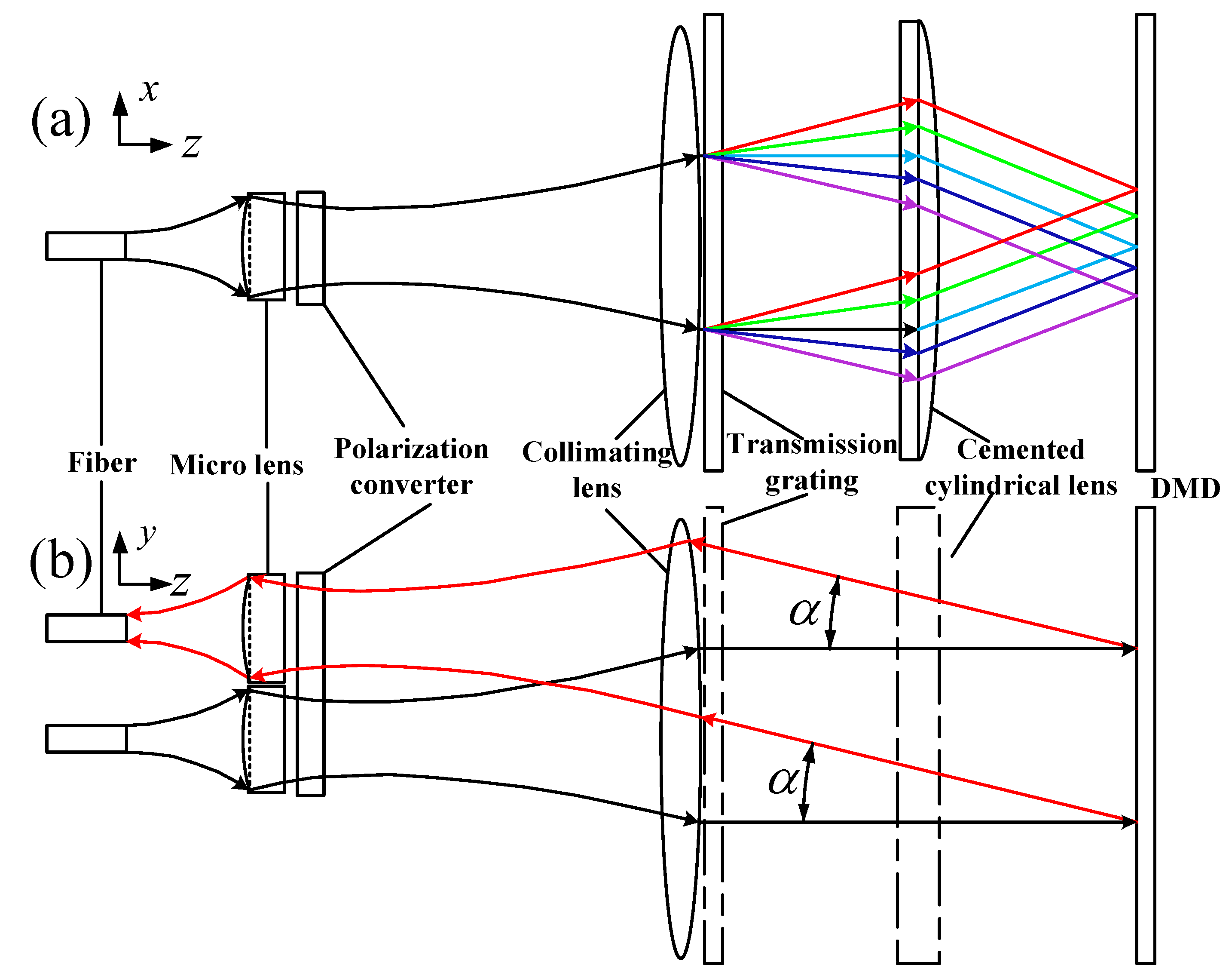
2. System Design
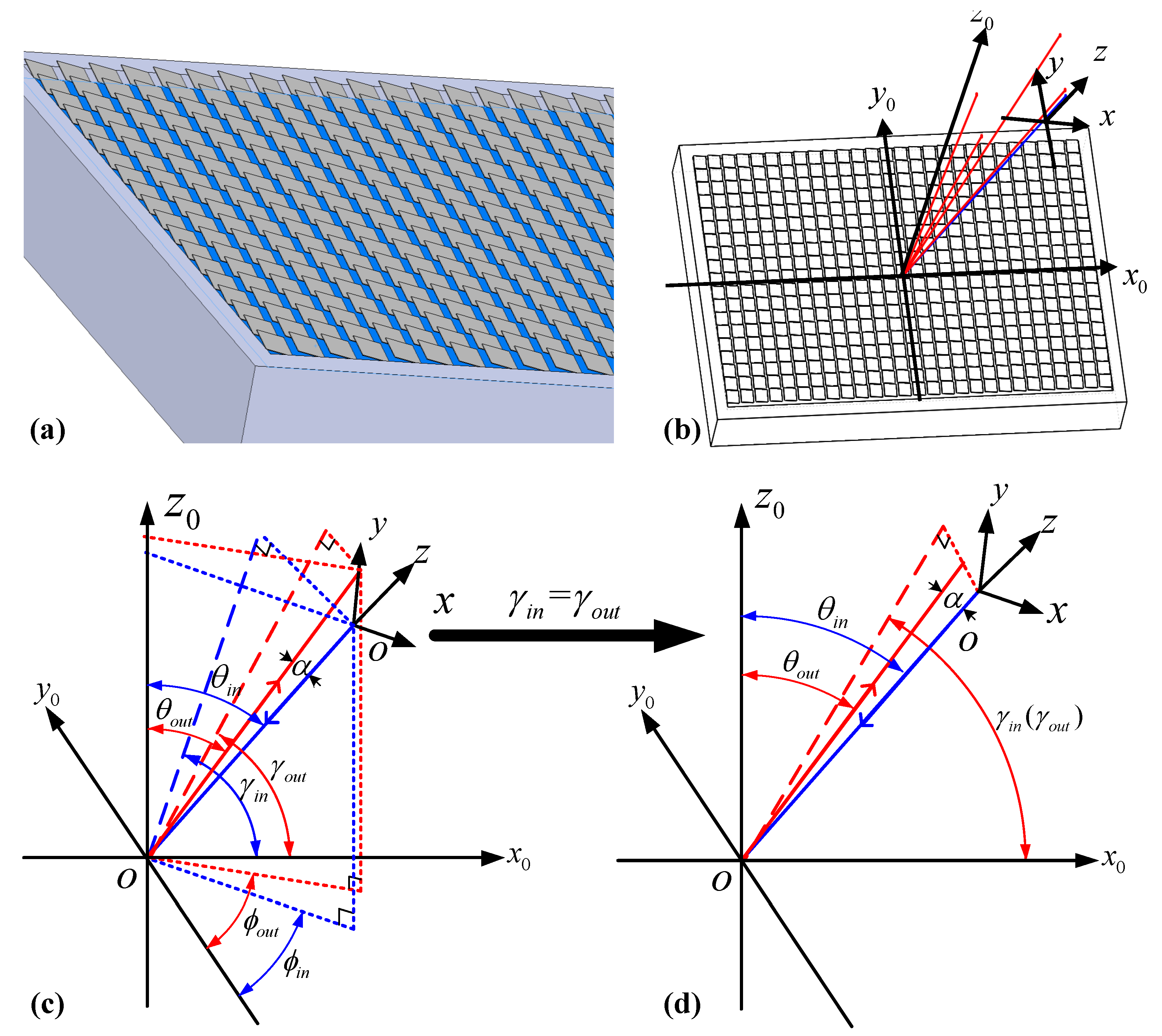
2.1. Diffraction Efficiency of DMD
2.2. Power Handling of Optical filter
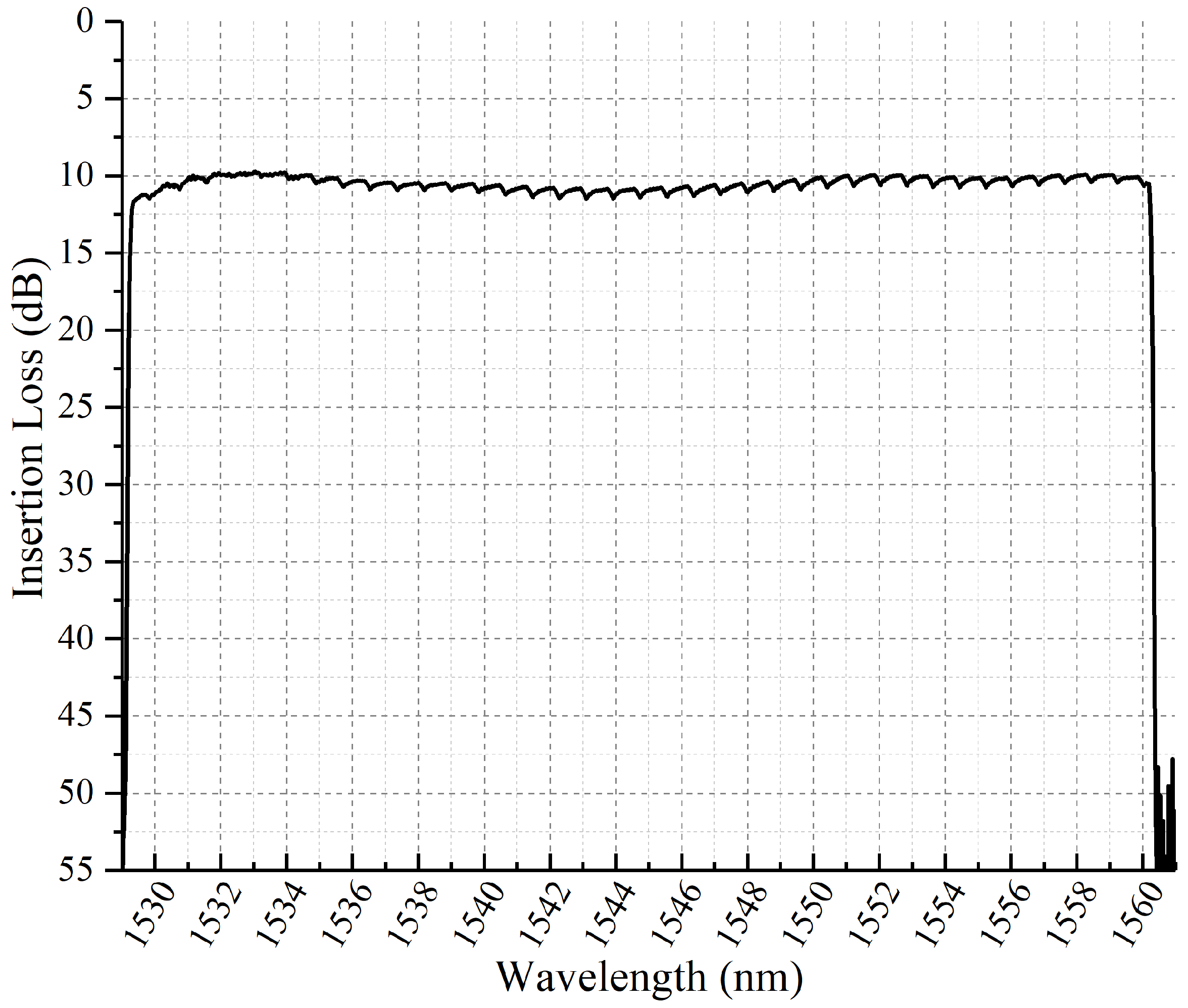
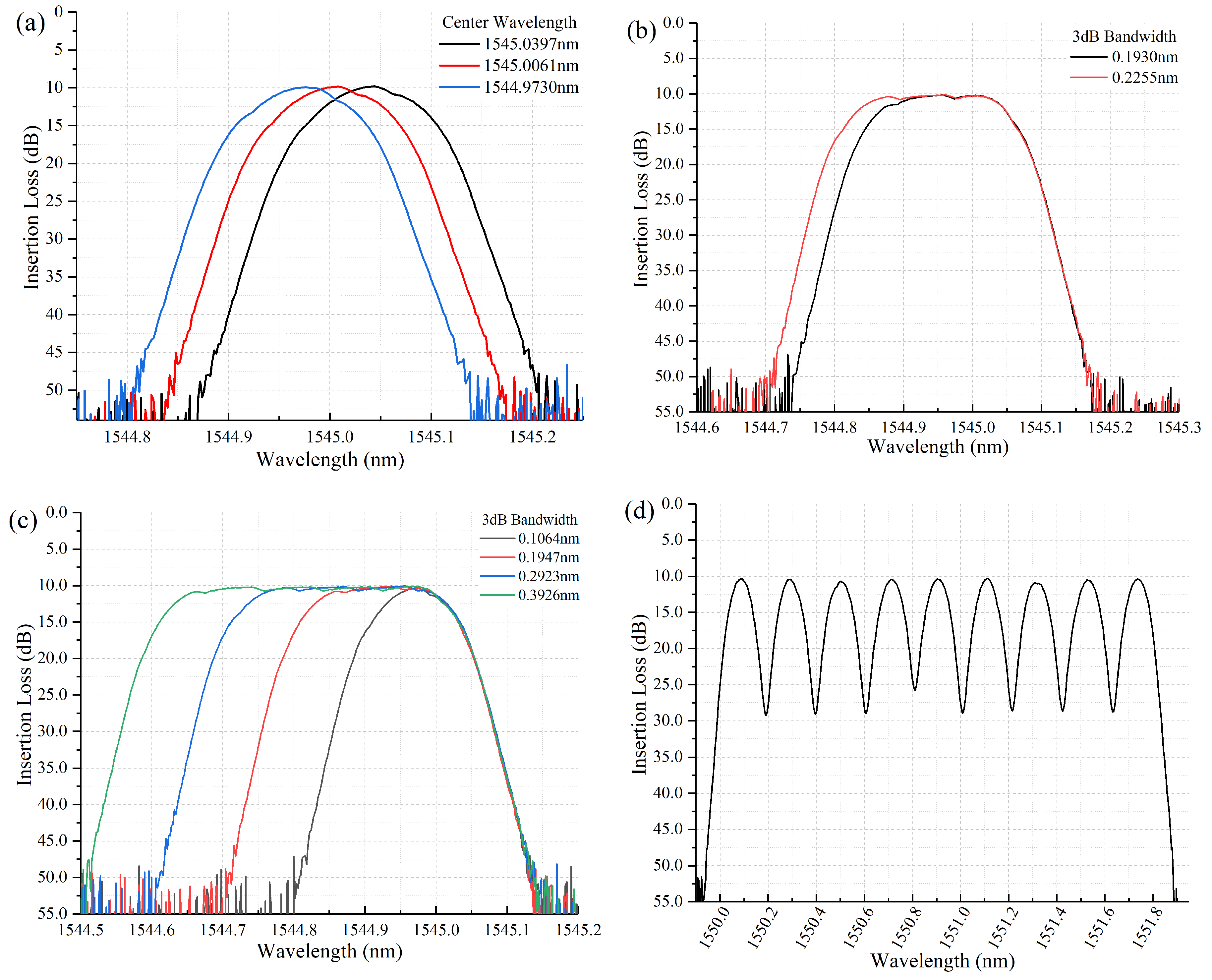
3. Experimental Results and Discussion
4. Conclusions
Author Contributions
Acknowledgments
Conflicts of Interest
References
- Anuj Malik, G.H. The Evolution of Next-Gen Optical Networks: Terabit Super-Channels and Flexible Grid ROADM Architectures. In Proceedings of the SCTE Cable-Tec Expo 2014, Denver, CO, USA, 22–25 September 2014. [Google Scholar]
- Woodward, S.L.; Feuer, M.D. Benefits and requirements of flexible-grid ROADMs and networks. IEEE/OSA J. Opt. Commun. Netw. 2013, 5, A19–A27. [Google Scholar] [CrossRef]
- Blanche, P.A.; Carothers, D.; Wissinger, J.; Peyghambarian, N. DMD as a diffractive reconfigurable optical switch for telecommunication. In Proceedings of the Emerging Digital Micromirror Device Based Systems and Applications V, San Francisco, CA, USA, 5–6 February 2013. [Google Scholar]
- Knapczyk, M.T.; de Peralta, L.G.; Bernussi, A.A.; Temkin, H. Reconfigurable add–drop optical filter based on arrays of digital micromirrors. J. Lightw. Technol. 2008, 26, 237–242. [Google Scholar] [CrossRef]
- Jin, D.; Zhou, R.; Yaqoob, Z.; So, P.T. Dynamic spatial filtering using a digital micromirror device for high-speed optical diffraction tomography. Opt. Express 2018, 26, 428–437. [Google Scholar] [CrossRef] [PubMed]
- Hoover, R.; Henry, A.; Arce, G.R. DMD-based implementation of patterned optical filter arrays for compressive spectral imaging. J. Opt. Soc. Am. A Opt. Image Sci. Vis. 2015, 32, 80–89. [Google Scholar]
- Liu, W.; Fan, J.; Xie, C.; Song, Y.; Gu, C.; Chai, L.; Wang, C.; Hu, M. Programmable controlled mode-locked fiber laser using a digital micromirror device. Opt. Lett. 2017, 42, 1923–1926. [Google Scholar] [CrossRef] [PubMed]
- Luo, D.; Taphanel, M.; Längle, T.; Beyerer, J. Programmable light source based on an echellogram of a supercontinuum laser. Appl. Opt. 2017, 56, 2359–2367. [Google Scholar] [CrossRef] [PubMed]
- Wood, T.C.; Elson, D.S. A tunable supercontinuum laser using a digital micromirror device. Meas. Sci. Technol. 2012, 23, 105204. [Google Scholar] [CrossRef]
- Chen, X.; Yan, B.B.; Song, F.J.; Wang, Y.Q.; Xiao, F.; Alameh, K. Diffraction of digital micromirror device gratings and its effect on properties of tunable fiber lasers. Appl. Opt. 2012, 51, 7214–7220. [Google Scholar] [CrossRef] [PubMed]
- Gu, C.; Chang, Y.; Zhang, D.; Cheng, J.; Chen, S.C. Femtosecond laser pulse shaping at megahertz rate via a digital micromirror device. Opt. Lett. 2015, 40, 4018–4021. [Google Scholar] [CrossRef] [PubMed]
- Khan, S.A.; Riza, N.A. Demonstration of the MEMS Digital Micromirror Device-Based Broadband Reconfigurable Optical Add–Drop Filter for Dense Wavelength-Division-Multiplexing Systems. J. Lightw. Technol. 2007, 25, 520–526. [Google Scholar] [CrossRef]
- Knapczyk, M.; Krishnan, A.; de Peralta, L.G.; Bernussi, A.; Temkin, H. High-resolution pulse shaper based on arrays of digital micromirrors. IEEE Photonics Technol. Lett. 2005, 17, 2200–2202. [Google Scholar] [CrossRef]
- Knapczyk, M.; Krishnan, A.; de Peralta, L.G.; Bernussi, A.; Temkin, H. Reconfigurable optical filter based on digital mirror arrays. IEEE Photonics Technol. Lett. 2005, 17, 1743–1745. [Google Scholar] [CrossRef]
- Xie, D.; Wang, D.; Zhang, M.; Liu, Z.; You, Q.; Yang, Q.; Yu, S. LCoS-based wavelength-selective switch for future finer-grid elastic optical networks capable of all-optical wavelength conversion. IEEE Photon. J. 2017, 9, 1–12. [Google Scholar] [CrossRef]
- Gao, Y.; Chen, G.; Chen, X.; Zhang, Q.; Chen, Q.; Zhang, C.; Tian, K.; Tan, Z.; Yu, C. High-Resolution Tunable Filter With Flexible Bandwidth and Power Attenuation Based on an LCoS Processor. IEEE Photonics J. 2018, 10, 1–8. [Google Scholar] [CrossRef]
- Carbajo, S.; Bauchert, K. Power handling for LCoS spatial light modulators. In Proceedings of the Laser Resonators, Microresonators, and Beam Control XX, San Francisco, CA, USA, 29 January–1 February 2018. [Google Scholar]
- Laser Power Handling for DMDs. Available online: http://www.ti.com/lit/wp/dlpa027/dlpa027.pdf (accessed on 26 February 2019).
- Iwama, M.; Takahashi, M.; Kimura, M.; Uchida, Y.; Hasesawa, J.; Kawahara, R.; Kagi, N. LCOS-based flexible grid 1 × 40 wavelength selective switch using planar lightwave circuit as spot size converter. In Proceedings of the 2015 Optical Fiber Communications Conference and Exhibition (OFC), Los Angeles, CA, USA, 22–26 March 2015; pp. 1–3. [Google Scholar]
- Suzuki, K.; Ikuma, Y.; Hashimoto, E.; Yamaguchi, K.; Itoh, M.; Takahashi, T. Ultra-high port count wavelength selective switch employing waveguide-based I/O frontend. In Proceedings of the Optical Fiber Communication Conference, Los Angeles, CA, USA, 22–26 March 2015. [Google Scholar]
- Faustov, A.R.; Webb, M.R.; Walt, D.R. Note: Toward multiple addressable optical trapping. Rev. Sci. Instrum. 2010, 81, 026109. [Google Scholar] [CrossRef] [PubMed]
- Schwarz, B.; Ritt, G.; Koerber, M.; Eberle, B. Laser-induced damage threshold of camera sensors and micro-optoelectromechanical systems. Opt. Eng. 2017, 56, 034108. [Google Scholar] [CrossRef]


| p/q | −4 | −3 | −2 | −1 |
|---|---|---|---|---|
| −4 | 22.8/45 (0.002) | 18.6/30.4 (0.035) | 16.1/9.9 (0.005) | - |
| −3 | 18.6/59.6 (0.019) | 13.2/45 (0.425) | 9.7/16.5 (0.05) | 10.0/−22.1 (0.009) |
| −2 | 16.1/80.1 (0.011) | 9.7/73.5 (0.213) | 3.872/45 (0.018) | 4.7/−54 (0.004) |
| −1 | −16.4/−76.6 (0.001) | −10.0/−67.9 (0.03) | −4.7/−36.1 (0.003) | - |
| Center Wavelength (nm) | 1550.09 | 1550.30 | 1550.50 | 1550.71 | 1550.91 | 1551.11 | 1551.32 | 1551.53 | 1551.74 |
|---|---|---|---|---|---|---|---|---|---|
| Offset Level (dB) | −0.557 | −0.25 | −0.067 | −0.029 | −0.502 | −0.267 | −0.124 | 0 | −0.419 |
| Channel Crosstalk (dB) | −16.345 | −16.46 | −16.132 | −14.677 | −14.223 | −15.93 | −15.739 | −15.677 | −16.319 |
© 2019 by the authors. Licensee MDPI, Basel, Switzerland. This article is an open access article distributed under the terms and conditions of the Creative Commons Attribution (CC BY) license (http://creativecommons.org/licenses/by/4.0/).
Share and Cite
Gao, Y.; Chen, X.; Chen, G.; Tan, Z.; Chen, Q.; Dai, D.; Zhang, Q.; Yu, C. Programmable Spectral Filter in C-Band Based on Digital Micromirror Device. Micromachines 2019, 10, 163. https://doi.org/10.3390/mi10030163
Gao Y, Chen X, Chen G, Tan Z, Chen Q, Dai D, Zhang Q, Yu C. Programmable Spectral Filter in C-Band Based on Digital Micromirror Device. Micromachines. 2019; 10(3):163. https://doi.org/10.3390/mi10030163
Chicago/Turabian StyleGao, Yunshu, Xiao Chen, Genxiang Chen, Zhongwei Tan, Qiao Chen, Dezheng Dai, Qian Zhang, and Chao Yu. 2019. "Programmable Spectral Filter in C-Band Based on Digital Micromirror Device" Micromachines 10, no. 3: 163. https://doi.org/10.3390/mi10030163
APA StyleGao, Y., Chen, X., Chen, G., Tan, Z., Chen, Q., Dai, D., Zhang, Q., & Yu, C. (2019). Programmable Spectral Filter in C-Band Based on Digital Micromirror Device. Micromachines, 10(3), 163. https://doi.org/10.3390/mi10030163