Abstract
C-SAR/01 and C-SAR/02 serve as successors to the GF-3 satellite. They are designed to operate in tandem with GF-3, collectively forming a C-band synthetic aperture radar (SAR) satellite constellation. This constellation aims to achieve 1 m resolution imaging with a revisit rate of one day. It can effectively cater to various applications such as marine disaster prevention, monitoring marine dynamic environments, and supporting marine scientific research, disaster mitigation, environmental protection, and agriculture. Geometric correction plays a pivotal role in acquiring highly precise geographic location data for ground targets. The geometric positioning accuracy without control points signifies the SAR satellite’s geometric performance. However, SAR images do not exhibit a straightforward image-point–object-point correspondence, unlike optical images. In this study, we introduce a novel approach employing high-precision automatic trihedral corner reflectors as ground control points (GCPs) to assess the geometric positioning accuracy of SAR images. A series of satellite-ground synchronization experiments was conducted at the Xilinhot SAR satellite calibration and validation site to evaluate the geometric positioning accuracy of different C-SAR image modes. Firstly, we calculated the azimuth and elevation angles of the corner reflectors based on satellite orbit parameters. During satellite transit, these corner reflectors were automatically adjusted to align with the radar-looking direction. We subsequently measured the exact longitude and latitude coordinates of the corner reflector vertex in situ using a high-precision real-time kinematics instrument. Next, we computed the theoretical image coordinates of the corner reflectors using the rational polynomial coefficients (RPC) model. After that, we determined the accurate position of the corner reflector in the Single Look Complex (SLC) SAR image using FFT interpolation and the sliding window method. Finally, we evaluated and validated the geometric positioning accuracy of C-SAR images by comparing the two coordinates. The preliminary results indicate that the positioning accuracy varies based on the satellite, imaging modes, and orbital directions. Nevertheless, for most sample points, the range positioning accuracy was better than 60 m, and the azimuth positioning accuracy was better than 80 m. These findings can serve as a valuable reference for subsequent applications of C-SAR satellites.
1. Introduction
The successive launches of high-resolution synthetic aperture radar (SAR) satellites in China have made it possible to efficiently access high-resolution SAR image data through satellite networking. Despite continuous enhancements in the resolution and radiometric quality of China’s satellite-borne SAR images, a substantial portion of this valuable data remains underutilized, resulting in considerable data wastage [1]. SAR satellite images are more susceptible to geometric distortions, such as foresight contraction, overlaying, and shadowing, compared to optical images. This susceptibility arises from their side-looking imaging characteristics [2], which are influenced by image geometry and topographic relief [3]. In various applications, like multi-source remote sensing image fusion analysis and multi-temporal SAR image comparison analysis, SAR images free from substantial geometric distortions and possessing precise geographic location information are often essential prerequisites [4]. Consequently, there is a pressing need to perform geometric corrections on SAR images, accurately project them into geographic coordinate systems, and quantitatively analyze their errors [5,6].
Geometric correction plays a crucial role in acquiring highly precise geographic location information of ground targets. The geometric positioning model of a spaceborne SAR system establishes a mathematical relationship between the three-dimensional spatial coordinates of a ground target point and the two-dimensional coordinates of the image plane of the corresponding image point. This model forms the fundamental basis for the geometric processing of spaceborne SAR data. In comparison to the Range-Doppler (RD) model [7,8], the rational polynomial coefficient (RPC) model offers versatility and is applicable to various sensor types, without the need for extensive knowledge of imaging parameters and sensor system characteristics [9]. It is user-friendly and simplifies the process. The RPC parameters are available for SAR image products from satellites like RADARSAT-2, a well-established commercial satellite [10]. Similarly, the C-SAR series satellites also provide RPC parameters within their files for image geometric correction. Zhang et al. [10] have theoretically demonstrated that the RPC model can effectively replace the RD model for spaceborne SAR images. They conducted experiments using multiple types of spaceborne SAR data, revealing that the RPC model can achieve a high level of fitting accuracy across SAR systems with varying resolutions. This makes the RPC model a valuable tool in the photogrammetric processing of SAR images.
SAR images lack the straightforward image-point–object-point correspondence commonly found in optical images. To assess geometric positioning accuracy in SAR images, control points within the SAR image are utilized. In contrast to distributed scattering targets, corner reflectors (CR) play a distinctive role. When the radar signal encounters a CR from a normal direction, it reflects the echo back towards the SAR system along the incident direction [11]. This reflection results in a distinct bright area on the SAR image, facilitating the accurate determination of the “bright spot” center [12], thereby achieving high-precision localization. Consequently, CRs are frequently employed as high-precision ground control points in SAR images. Balss et al. [13] conducted ground measurements to obtain the geographic coordinates of CRs, translating them into theoretical values. They then compared these theoretical values with the range-azimuth pixel position of the CRs in the image. Their findings demonstrated that TerraSAR-X and TanDEM-X could achieve centimeter-level localization accuracy under ideal conditions [14]. Additionally, Zhao [1] developed a high-precision geometric calibration method for SAR satellites. This method involved error analysis and model construction, incorporating interpolation techniques to enhance the image pixel position accuracy to the sub-pixel level. A mathematical model was constructed to depict the relationship between the pixel gray values in the target region and centroid position, thereby enabling the precise estimation of the target position.
C-SAR/01 and C-SAR/02, the successors to the GF-3 satellite, have been designed to be integrated with GF-3, forming a C-band synthetic aperture radar (SAR) satellite constellation. This constellation is capable of achieving 1 m resolution imaging with a daily revisiting frequency. Such capabilities cater to a wide range of applications, including marine disaster prevention, monitoring marine dynamics, facilitating marine scientific research, aiding in disaster mitigation, supporting environmental protection efforts, and bolstering agricultural activities, among others. Following the launch of C-SAR/01 and C-SAR/02, a comprehensive series of experiments was conducted at the Xilinhot SAR satellite calibration and validation site. These experiments received support from the Common Application Support Platform project for Land Observation Satellites within China’s Civil Space Infrastructure (CASPLOS_CCSI). The primary aim of these experiments, which took place between October and November 2022, was to assess the radiometric and geometric accuracy of C-SAR satellites. During the experiments, 11 C-SAR images were acquired across multiple modes. To evaluate the geometric positioning accuracy of these SAR images, a methodology employing high-precision automatic trihedral corner reflectors as ground control points (GCPs) was employed. In this study, we present the preliminary evaluation results stemming from these experiments.
This paper is structured as follows: Section 2 provides an introduction to the study area and data used in this experiment. Section 3 outlines the proposed method, which involves utilizing high-precision automatic trihedral corner reflectors as GCPs for assessing the geometric positioning accuracy of SAR images. Finally, Section 4 presents the preliminary findings related to the geometric positioning accuracy of the C-SAR series data. Furthermore, this section discusses the differences in positioning accuracy between the various imaging modes of C-SAR satellites.
2. Study Area and Data
2.1. Experimental Area
Between October and November 2022, a comprehensive series of in-orbit tests and experiments was carried out on the C-SAR satellites at the Xilinhot SAR satellite calibration and validation site. These endeavors were made possible through the support of the CASPLOS_CCSI. During this time frame, the geometric positioning accuracy of the C-SAR data series was thoroughly assessed and validated, employing automatic trihedral CRs. The study area was centered around the Xilinhot SAR satellite calibration and validation site, encompassing an approximate 20 km × 20 km region. The predominant surface features in this area comprise grassland, farmland, and low houses, with an elevation ranging from 1090 m to 1160 m. Notably, the study site is devoid of prominent targets or electromagnetic interference, thereby allowing for the effective reduction in background clutter interference [15].
Throughout the experimental timeframe, a total of 11 C-SAR images were obtained. In support of C-SAR satellite radiometric and geometrical calibration and validation, 15 automatic CRs were enlisted. To execute satellite-ground synchronization experiments, two deployment schemes were sequentially employed, as delineated in Figure 1. The first deployment scheme was enacted between October 14 and November 10, followed by the implementation of the second deployment scheme that took place from November 11 to November 22.
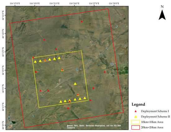
Figure 1.
Two deployment schemes for automatic CRs in the experimental area.
2.2. Experimental Data
GF-3 is China’s first C-band full-polarization SAR satellite. It was successfully launched on 10 August 2016. Subsequently, C-SAR/01 and C-SAR/02, its two successor satellites, were launched on 23 November 2021 and 7 April 2022, respectively. These C-SAR satellites, boasting a remarkable 1 m resolution, along with the Gaofen-3 scientific test satellites, collectively constitute China’s comprehensive constellation of ocean surveillance and monitoring satellites. For a comprehensive understanding of the GF-3 satellite’s parameters, please refer to the provided reference [16]. Both C-SAR/01 and C-SAR/02 belong to the C-band category and share the same fundamental parameters as GF-3. Details regarding specific imaging modes are presented in Table 1.

Table 1.
Imaging modes and parameters of GF-3.
In this study, Level-1A Single Look Complex (SLC) images were employed as the primary data sources. These images were acquired during the period of October to November 2022, encompassing two GF-3 images, four C-SAR/01 images, and five C-SAR/02 images. Figure 2 depicts the respective data extents for these three satellites, delineated by double (GF-3), dashed (C-SAR/01), and solid lines (C-SAR/02). Different satellite imaging modes, namely ultrafine strip (UFS), fine strip I (FSI), quad polarization strip I (QPSI) [16], fine strip II (FSII), and quad polarization strip II (QPSII), are represented in Figure 2 with different colors. To differentiate images captured on different dates but belonging to the same satellite and mode, the lines vary in width. Among these modes, the FSII mode (indicated by a blue border) boasted the broadest image coverage, followed by the FSI mode (marked by a green border) and QPSII mode (displayed with a yellow border). In contrast, the UFS mode (represented by a purple border) and QPSI mode (denoted by an orange border) had the smallest coverage. Three of the images were captured during ascending orbit right-look and eight were acquired during descending orbit right-look. The detailed parameters of each image are shown in Table 2.
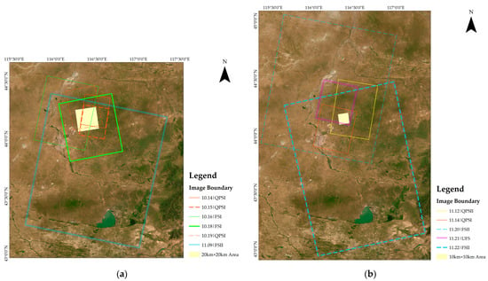
Figure 2.
Acquisition footprints over the target area. (a) Images acquired during the first deployment scheme. (b) Images acquired during the second deployment scheme.

Table 2.
Main parameters of C-SAR images obtained in the experiment.
3. Methods
To assess the geometric positioning accuracy of various common imaging modes of the C-SAR satellite, the methodology outlined in Figure 3 was employed. Initially, automatic CRs were placed within the calibration field. Real-time kinematics (RTK) was utilized to measure the latitude, longitude coordinates, and elevation information of the CRs. When the satellite passed overhead, calculations were made to determine the azimuth and elevation angles of the CRs, ensuring that the calibrator had a strong echo signal and imaging. Next, using the RPC parameters [17] extracted from the image file, the corresponding theoretical row and column number positions of the CRs on the SLC image were derived. Then, in the SLC image, a local region encompassing the point target was identified. Subsequently, employing the Fast Fourier Transform (FFT) zero-padding interpolation [18] technique in conjunction with the sliding window method [19], the precise row–column coordinates of the point target’s center position were extracted. The final step involved the evaluation and analysis of geometric positioning accuracy. This was accomplished by comparing the theoretical row–column numbers, calculated from the latitude, longitude, and RPC parameters, with the actual row–column numbers extracted from the SLC image.
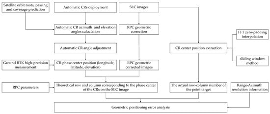
Figure 3.
Experimental method flow.
3.1. Calculating Azimuth and Elevation Angles for Automatic CRs and Conducting In Situ Measurements
The ground experiment made use of 15 automatic CRs, as depicted in Figure 4, which were developed by CASPLOS_CCSI and employed as the ground control points. Each of these 15 sets of trihedral CRs had an inner leg length of 1 m. They exhibited radar cross section errors of less than 0.16 dB in the C-band. The console was situated beneath the CR and the azimuth and elevation angle adjustment errors were less than ±0.1°.
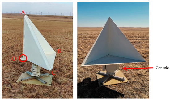
Figure 4.
Automatic trihedral CR (the letters on the 4 vertices of the corner reflector correspond to the vertex positions in Figure 6).
In this experiment, the iRTK5 device, as illustrated in Figure 5, was employed to measure the latitude/longitude position and elevation information of the phase center of the CR, indicated by the red circle in Figure 4. The iRTK5 is equipped with a professional GNSS antenna, ensuring stable operation even in complex environments. It maintains a data measurement error of less than 9 mm for dynamic data acquisition and 2.5 mm for static data acquisition, adhering to D-level surveying and mapping standards [20]. This level of precision effectively guarantees the positional accuracy of the CRs and the accuracy of the subsequent angle calculations and other processes.
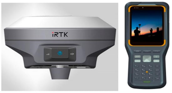
Figure 5.
RTK instrument used for the location of CR in in situ measurements.
During the transit of SAR satellites, it is crucial to align the normal angle of the CR with the radar incident beam direction [21] to maximize the backscattered echoes and ensure the point target is clearly visible in the image. To achieve this, the satellite’s orbital parameters are employed to calculate its azimuth and elevation angles during transit [22]. Based on the spatial geometric relationship between the satellite and the ground, we calculated the azimuth angle (defined as the angle between the CR’s direction towards the satellite S and due north, indicated by the red arc in Figure 6a) and the elevation angle (defined as the angle between the CR’s direction towards the satellite S and the horizon plane, marked by the red arc in Figure 6b) of the satellite. Then, we determined the azimuth angle and elevation angle of the CR (the vertexes of the CR, O, A, B, and C are shown in Figure 4) based on our previous work in [23]. For instance, when the satellite is in the descending orbit and right-looking, the geometric relationship between the CR’s azimuth angle and the satellite azimuth angle is shown in Figure 6a, and the geometric relationship between the CR’s elevation angle and the satellite elevation angle is shown in Figure 6b. Notably, the angle between the normal direction and the bottom surface of the trihedral corner reflector is 35.264°.
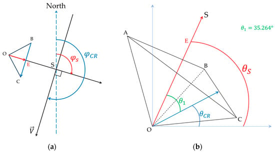
Figure 6.
Schematic for the calculation of CR’s azimuth and elevation angles: (a) azimuth angle calculation and (b) elevation angle calculation.
3.2. Geometric Correction of C-SAR Images Based on RPC Model and Theoretical Row–Column Coordinate Calculation for Ground CRs
The RPC model was employed for the correction of C-SAR images. This model is versatile and adaptable to various sensor types, eliminating the need for complex knowledge about imaging processes and sensor system characteristics. This simplifies and expedites photogrammetric processing, making it user-friendly even when dealing with new sensor parameters [24].
Presently, geometric correction parameters based on RPC models are provided for GF-3, C-SAR/01 and C-SAR/02 [25]. Therefore, in this study, the RPC model was utilized to establish a correlation between the geodesic coordinates of the ground point (P, L, H) and the corresponding image point coordinates (Y, X) using Equation (1).
In Equation (1),
where , , , and are the RPC model coefficients. and are typically 1.
To ensure the stability of parameter solving, standardization of ground and image coordinates between −1 and 1 is essential. Consequently, (P, L, H) represents the ground coordinates achieved by standardizing (Latitude, Longitude, Height), while (Y, X) denotes the image coordinates achieved by standardizing (Line, Sample). The standardization formula is as follows:
where LINE_OFF and SAMP_OFF refer to the offset values of the image pixel coordinates and LINE_SCALE and SAMP_SCALE are the scale values of the image pixel coordinates. Similarly, LAT_OFF, LONG_OFF, and HEIGHT_OFF denote the offset values of the ground coordinates. LAT_SCALE, LONG_SCALE, and HEIGHT_SCALE are the scale values of the ground coordinates.
Figure 7a,b depict the RPC geometric correction outcomes for the C-SAR/02 FSI mode image on October 18 and the C-SAR/01 FSII mode image on November 22, respectively. During the transit of the C-SAR/02 image on October 18, the first deployment scheme was employed, while the second scheme was used during the transit of the C-SAR/01 image on November 22. Figure 7c,d showcase the geometric correction results utilizing the RPC model for the two images and provide the location of the ground CRs and detailed image features. With the high-precision latitude and longitude data obtained from the ground measurements of each CR and the RPC parameters of the image, it becomes possible to compute the corresponding row and column values for each automatic CR in the Level-1 image.
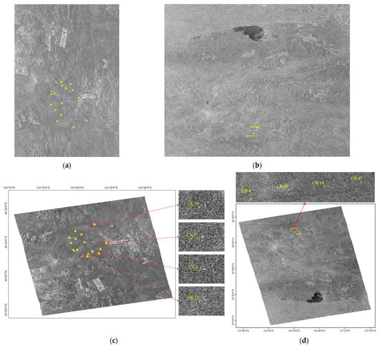
Figure 7.
Example of RPC geometric correction results for C-SAR images (the yellow triangles in the figure represent the theoretical positions of the corner reflectors in the figure): (a) October 18 C-SAR/02 FSI mode image in SLC, (b) November 22 C-SAR/01 FSII mode image in SLC, (c) October 18 C-SAR/02 FSI image after geometric correction using the RPC model and a detailed image for CRs, and (d) November 22 C-SAR/01 FSII image after geometric correction using the RPC model and a detailed image for CRs.
3.3. CR Location Extraction Based on FFT Interpolation and the Sliding Window Method
The precise extraction of CR coordinates from SAR images has a direct impact on the accuracy of geometric validation. However, accurately pinpointing CR positions in the original SAR images can be challenging due to limited resolution or unclear details. To address this issue, we employed an approach involving FFT interpolation and the sliding window method to accurately determine the phase center position of CR from SLC images.
Utilizing the grayscale distribution characteristics of the target image points, we applied an interpolated subdivision algorithm to locate target image points, achieving sub-pixel level measurement accuracy. When determining the phase center position of the point target, we utilized the 8-fold FFT zero-padding interpolation algorithm [18] to interpolate the local signals around the point target by initially performing an FFT of the signals in the time domain, and then performing zero-padding in the high frequencies (i.e., the middle portion of the signals in the frequency domain) to produce the interpolation effect in the time domain. In Figure 8a identifies the point target before interpolation, Figure 8b illustrates the result after zero-padding the spectrum, and Figure 8c displays the point target after interpolation. The white cross-shaped dashed box in Figure 8b identifies the regions with invalid spectral regions that can be zeroed and for which extended point targets can be obtained by inverting the 2D discrete FFT after zero-padding.
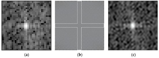
Figure 8.
Schematic of FFT interpolation: (a) point target before interpolation, (b) frequency graph after zero padding, and (c) point target after interpolation.
A buffer is created using the center-of-maximum method and is shifted within the buffer using a suitably sized adaptive window [19]. The sum of pixel values within the adaptive window is calculated. When the sum of values reaches its maximum, the center of the adaptive window is considered as the center of the CR. Specifically, this window size is usually determined based on the width of the point target side lobe before interpolation. In real applications, this value still needs to be determined based on experimental results.
We analyzed the impulse response function of the interpolated point target in terms of resolution, peak sidelobe ratio, and integral sidelobe ratio using the method described in reference [23], as shown in Figure 9. CR-4 in the GF-3 UFS mode image acquired on November 21 is used as an example. The spatial resolution is usually expressed in terms of the impulse response width (IRW), i.e., the −3 dB width of the main lobe of the impulse response function of the point target. The Peak Sidelobe Ratio (PSLR) is defined as the ratio of the first sidelobe intensity of the point target impulse response to the peak intensity of the main lobe. The Integral Sidelobe Ratio (ISLR) is the ratio of the sidelobe energy to the main lobe energy in the impulse response profile of a point target. The resolution is an important indicator of the ability of the image to distinguish ground point targets, the PSLR describes the extent to which the weak scattering points are masked by the strong scattering points, and the ISLR measures the energy that overflows from the main lobe to the sidelobe [23], which characterize different aspects of the image quality. The evaluated resolutions in the range and azimuth directions were 1.214 m and 2.164 m, respectively. These values are superior to the nominal resolution of 3 m. The calculated peak sidelobe ratios (PSLR) in the range and azimuth directions were −22.681 dB and −23.539 dB, respectively, surpassing the design index of GF-3, which is −22 dB. The calculated integrated sidelobe ratios (ISLR) were −21.575 dB and −17.166 dB, which are better than that of the design index of −15 dB.
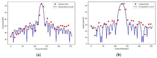
Figure 9.
Impulse response function of CR-4 in the GF-3 UFS mode image acquired on November 21. (a) Range impulse response function and (b) azimuthal impulse response function.
Similarly, since synthetic aperture sonar (SAS) [26,27] is similar in principle to SAR, the FFT interpolation and selection of the center of the point target with a sliding window used in this section are also applicable to SAS.
4. Results and Discussion
Table 2 lists information on the C-SAR satellite data used in the experiment. Specifically, C-SAR/01 comprises the QPSI and FSII modes, C-SAR/02 includes the QPSI, QPSII, and FSI modes, and GF-3 incorporates the FSII and UFS modes. The experimental data were classified and analyzed according to different satellites and imaging modes. In order to provide a more intuitive comparison of positioning accuracy for different imaging modes of different satellites, we conducted classification mapping and discussions. Some of the data points are not visible in the image, either because certain equipment was not adjusted on the day of the satellite transit or due to the image’s coverage area.
4.1. C-SAR/01
- (1)
- QPSI mode localization accuracy analysis
The C-SAR/01 satellite QPSI model contained data of October 15 and October 19, and the positioning accuracy obtained is shown in Figure 10.
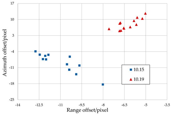
Figure 10.
Localization accuracy of C−SAR/01 QPSI mode data.
Figure 10 illustrates that the images of October 15 and 19 contain 12- and 13-point targets, respectively. In the case of the QPSI mode images of C-SAR/01, the positioning accuracy falls within the range of −14 to −4 pixels in the range direction and between −19 and 13 pixels in the azimuth direction.
- (2)
- FSII mode localization accuracy analysis
The C-SAR/01 FSII data contained data of November 20 and November 22, and the positioning accuracy obtained is shown in Figure 11.
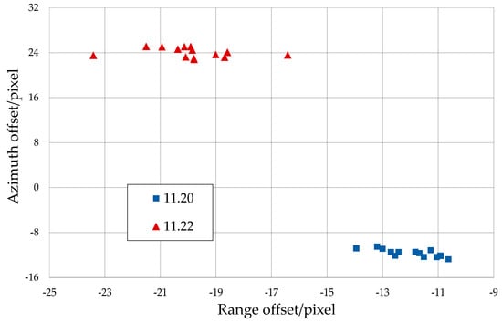
Figure 11.
Localizaion accuracy of C−SAR/01 FSII mode data.
Figure 11 indicates that both the images of November 20 and 22 contain 14-point targets. In the case of the FSII mode images of C-SAR/01, the positioning accuracy varies from −24 to −10 pixels in the range direction and from −13 to 26 pixels in the azimuth direction.
4.2. C-SAR/02
- (1)
- QPSI mode localization accuracy analysis
The C-SAR/02 satellite QPSI model contains data of October 14 and November 14, and the positioning accuracy obtained is shown in Figure 12.
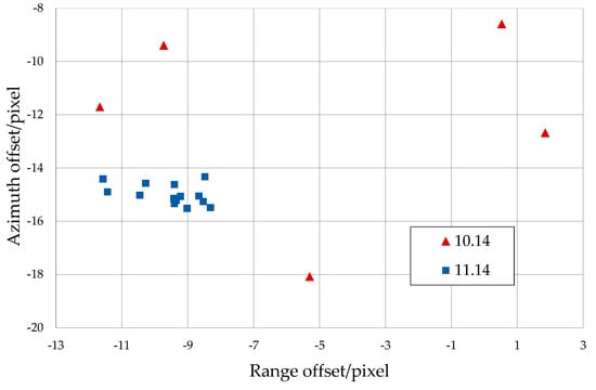
Figure 12.
Localization accuracy of C−SAR/02 QPSI mode data.
As can be seen from Figure 12, the image on October 14 contained only 5-point targets because some of the equipment was used to perform the imaging experiment on the following day. The image on November 14 contained 14-point targets. In the case of the QPSI mode images of C-SAR/02, the positioning accuracy ranges from −12 to 2 pixels in the range direction and from −19 to −8 pixels in the azimuth direction.
- (2)
- QPSII mode localization accuracy analysis
The positioning accuracy of the QPSII mode data of C-SAR/02 satellite obtained using this method is shown in Figure 13.
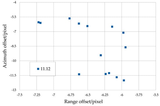
Figure 13.
Localization accuracy of C−SAR/02 QPSII mode data.
Figure 13 indicates that the image from November 12 contains 14-point targets. In the case of the QPSII mode image of C-SAR/02, the positioning accuracy ranges from −7.25 to −5.75 pixels in the range direction and between −12 and −5.5 pixels in the azimuth direction.
- (3)
- FSI mode localization accuracy analysis
The C-SAR/02 satellite FSI mode data contained data of October 16 and October 18. The positioning accuracy obtained is shown in Figure 14.
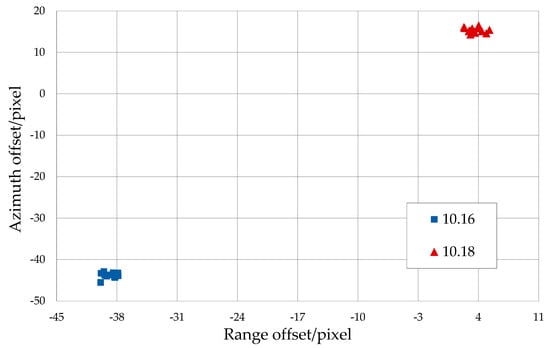
Figure 14.
Localization accuracy of C−SAR/02 FSI mode data.
Figure 14 illustrates that the images of October 16 and 18 contain 11- and 14-point targets, respectively. The positioning errors of the two FSI mode images of C-SAR/02 exhibit significant differences. The positioning errors of the CRs in the image of October 16 are approximately between −40 and −37 pixels in the distance direction and −46 and −42 pixels in the azimuth direction. The positioning errors of the CRs on the image of October 18 are approximately between 2 and 6 pixels in the distance direction and approximately 14 and 17 pixels in the azimuth direction.
4.3. GF-3
The GF3 data included the FSII mode data on November 9 and UFS mode data on November 21.
- (1)
- FSII mode localization accuracy analysis
The positioning accuracy of the FSII data for November 9 obtained using the above method is shown in Figure 15.
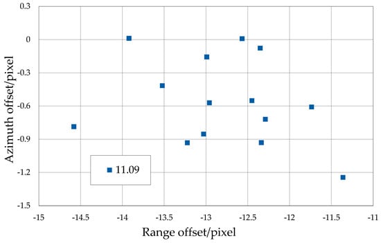
Figure 15.
GF−3 FSII mode data localization accuracy.
Figure 15 illustrates that the image from November 9 contains 14-point targets, and in the FSII mode image of GF-3, the positioning accuracy falls between −15 and −11 pixels in the range direction and between −2 and 0.5 pixels in the azimuth direction.
- (2)
- UFS mode localization accuracy analysis
For the UFS data for November 21, the positioning accuracy obtained is shown in Figure 16.
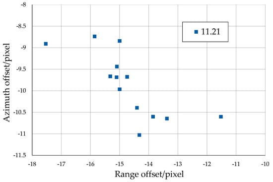
Figure 16.
GF−3 UFS mode data localization accuracy.
Figure 16 shows that the image from November 21 contains 13-point targets. In the UFS mode image of GF-3, the positioning accuracy is between −18 and −11 pixels in the range direction and between −11.5 and −8 pixels in the azimuth direction.
4.4. Analysis and Discussion
The latitude and longitude of each CR are converted to theoretical ranks using Equations (1)–(3) and RPC parameters. We compared the actual ranks of the CRs extracted from the Level 1A-SLC images with the theoretical ranks to obtain the range and azimuth pixel localization accuracies of the images, and converted the pixel position errors to distance errors based on the ranging and azimuthal pixel spacing. The results shown in Table 3 are obtained after summarizing and analyzing the image localization accuracy for different dates.

Table 3.
Localization accuracy analysis for each experimental image.
According to Table 3, the geometric positioning accuracy of CRs within the same image exhibits clustering. Except for the high positioning errors of the October 16 C-SAR/02 FSI image and the November 22 C-SAR/01 FSII image, the range-direction positioning accuracy of most CRs is better than 60 m, and the azimuth-direction positioning accuracy is better than 80 m.
The imaging satellites, imaging modes, imaging time, orbit direction, and other information of the 11 images were combined and comprehensively analyzed to obtain the results shown in Figure 17, Figure 18 and Figure 19. The localization error of the point target in each image varied slightly with the satellite, imaging mode, and orbit direction.
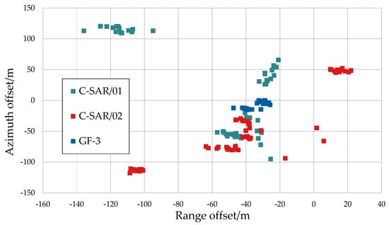
Figure 17.
Distribution of the positioning accuracy of the C−SAR series satellites.
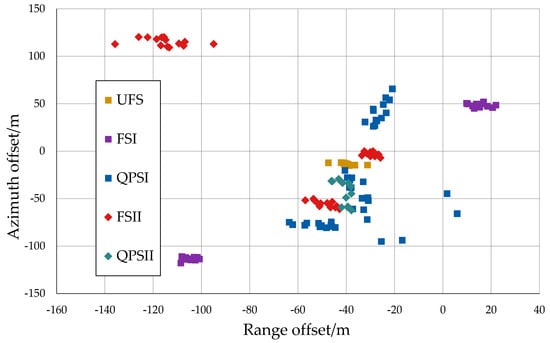
Figure 18.
Positioning accuracy of different imaging modes of the C−SAR series satellites.
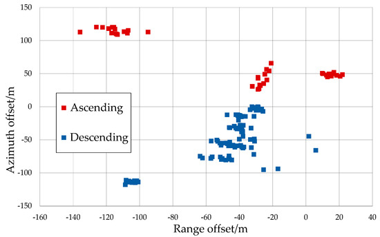
Figure 19.
Positioning accuracy of different orbital directions of the C−SAR series satellites.
With respect to the three satellites, the positioning error of the GF-3 image was the smallest, with the range-direction error being less than 50 m and the azimuth-direction error being less than 15 m. This can be attributed to GF-3′s extended operational history and regular geometric calibration, ensuring its high positioning accuracy. The overall positioning errors of the C-SAR/01 and C-SAR/02 satellites were larger than those of GF-3.
The errors of the FSII mode of the C-SAR/01 satellite in both the range and azimuth directions were greater than 100 m. On October 16, the FSI mode of the C-SAR/02 satellite had an error greater than 100 m in both the range and azimuth directions, but the FSI mode of the C-SAR/02 satellite on October 18 had an error of less than 20 m in the range direction and 50 m in the azimuth direction.
In addition, all the experimental images were divided into ascending and descending orbit (all right-looking). An analysis of their positioning accuracy errors revealed that those of ascending orbit images were positive in the azimuthal direction and were mostly less than 80 m and those of descending images were all negative in the azimuthal direction and were mostly less than 100 m.
4.5. Analysis of Potential Reasons and Future Work Plan
Although there are notable errors in the obtained positioning accuracy results, they still meet the geometric positioning accuracy index without control points (230 m) proposed by official satellites [25]. Most of the Chinese SAR satellites, such as GF-3, C-SAR/01, C-SAR/02, etc., adopt the RPC mode, so the main parameters affecting the positioning accuracy of level 1B products are the RPC parameters [28]. In the process of generating these parameters by satellite data producers, due to the special imaging mechanism of SAR, its geometric accuracy will be affected by various complex error sources, such as the performance of the sensor itself, the satellite platform, the imaging processing, the observing environment, and the observing targets in the ground observation process. Moreover, since data producers provide a large number of data products, it is not fully guaranteed that the generated RPC parameters are applicable to images from various regions and modes.
The main factors affecting the geometric positioning accuracy of spaceborne synthetic aperture radar (SAR) can be summarized as sensor instability, platform instability, signal propagation effect, terrain height and processor-induced errors [1]. However, these reasons are rather mixed and expressed only in the form of RPC parameters in the end, so we can only hope to analyze them to some extent by comparing the parameters of different data. Different imaging satellites have different sensors, platforms and processors. Figure 17 shows the differences in positioning accuracy between the different satellites, and it can be seen that the errors of the three satellites are not significantly different. This part of the error is related to the electronic delay of the satellite sensors, the drift of the space clock, and the position and velocity errors of the platforms. Since our experimental area is the same experimental area and most of it is flat grassland, the influence of the terrain is ignored, and the accuracy of the latitude, longitude and elevation data of the corner reflector is guaranteed by the iRTK equipment, so these errors are not considered for the time being. For the orbit, we only analyze it from the perspective of the orbit direction, and according to Figure 19, it can be seen that the errors of the ascending orbit data are all positive, and the errors of the descending orbit data are all negative, which indicates that there is still some systematic bias in the satellite orbit data, which needs to be eliminated.
In the subsequent work, we will conduct more ground experiments and acquire more images. The Range-Doppler model will be constructed based on the current validation work to confirm these assumptions and optimize them step by step. We will also correct the model error by considering the atmospheric delay and using the corner reflectors as control points to obtain higher geometric accuracy results.
5. Conclusions
This study introduced a method to validate the geometric positioning accuracy of SAR images using high-precision automatic trihedral CRs as ground control points. We evaluated the geometric positioning accuracy of the recently launched C-SAR/01 and C-SAR/02 through a series of experiments conducted at the Xilinhot SAR satellite calibration and validation site. The initial findings indicate that the geometric positioning errors of C-SAR images, without the use of control points, were influenced by various factors including the satellite, imaging mode, orbit directions, and others. With the exception of two images that displayed positioning errors near 150 m, most CRs in the other images achieved a range-direction positioning accuracy better than 60 m and an azimuth-direction positioning accuracy better than 80 m. Consequently, the C-SAR series of satellites can ensure the required geometric accuracy for subsequent applications.
Author Contributions
Y.J. wrote the manuscript and designed the comparative experiments; F.Z. supervised the study and revised the manuscript; Q.H. and Z.H. assisted Y.J. in designing the article structure and conducting experiments. X.L. and Q.W. assisted Y.J. in obtaining experimental data. All authors have read and agreed to the published version of the manuscript.
Funding
This work was supported by the National Key R&D Program of China (No.2022YFC2807000/2022YFC2807003), the Common Application Support Platform for Land Observation Satellites of China’s Civil Space Infrastructure (CASPLOS_CCSI), and the China High-resolution Earth Observation System (21-Y20B01-9003-19/22).
Data Availability Statement
Not applicable.
Conflicts of Interest
The authors declare no conflict of interest.
References
- Zhao, R. Research on Model and Method of Geometric Calibration for Space-Borne SAR. Ph.D. Thesis, Liaoning Technical University, Fuxin, China, 2017. [Google Scholar]
- Deng, M.; Zhang, G.; Zhao, R.; Li, S.; Li, J. Improvement of Gaofen-3 Absolute Positioning Accuracy Based on Cross-Calibration. Sensors 2017, 17, 2903. [Google Scholar] [CrossRef] [PubMed]
- Jiang, W.; Yu, A.; Dong, Z.; Wang, Q. Comparison and Analysis of Geometric Correction Models of Spaceborne SAR. Sensors 2016, 16, 973. [Google Scholar] [CrossRef] [PubMed]
- Choo, A.L.; Chan, Y.K.; Koo, V.C.; Lim, T.S. Study on geometric correction algorithms for SAR images. Int. J. Microw. Opt. Technol. 2014, 9, 68–72. [Google Scholar]
- Small, D.; Rosich, B.; Schubert, A.; Meier, E.; Daniel, N. Geometric Validation of Low and High-Resolution ASAR Imagery. In Proceedings of the 2004 Envisat & ERS Symposium, Salzburg, Austria, 6–10 September 2005. [Google Scholar]
- Luo, H.B.; He, X.F.; He, M. Error analysis of pixel positioning accuracy of SAR images based on R-D location model. In Proceedings of the Asian & Pacific Conference on Synthetic Aperture Radar, Huangshan, China, 5–9 November 2007. [Google Scholar]
- Curlander, J.C. Location of Spaceborne Sar Imagery. IEEE Trans. Geosci. Remote Sens. 1982, GE-20, 359–364. [Google Scholar] [CrossRef]
- Liu, J.; Qiu, X.; Hong, W. Automated ortho-rectified SAR image of GF-3 satellite using Reverse-Range-Doppler method. In Proceedings of the IGARSS 2016, Beijing, China, 10 July 2016. [Google Scholar]
- Tao, C.; Hu, Y. A Comprehensive study of the rational function model for photogrammetric processing. Photogramm. Eng. Remote Sens. 2001, 67, 1347–1357. [Google Scholar]
- Zhang, G.; Fei, W.; Li, Z. Analysis and Test of the Substitutability of the RPC Model for the Rigorous Sensor Model of Spaceborne SAR Imagery. J. AGCS 2010, 39, 264–270. [Google Scholar]
- Eineder, M.; Minet, C.; Steigenberger, P.; Cong, X.; Fritz, T. Imaging Geodesy—Toward Centimeter-Level Ranging Accuracy with TerraSAR-X. IEEE Trans. Geosci. Electron. 2011, 49, 661–671. [Google Scholar] [CrossRef]
- Garthwaite, M. On the Design of Radar Corner Reflectors for Deformation Monitoring in Multi-Frequency InSAR. Remote Sens. 2017, 9, 648. [Google Scholar] [CrossRef]
- Balss, U.; Gisinger, C.; Cong, X.Y.; Brcic, R.; Hackel, S.; Eineder, M. Precise Measurements on the Absolute Localization Accuracy of TerraSAR-X on the Base of Far-Distributed Test Sites. In Proceedings of the EUSAR 2014, Berlin, Germany, 3–5 June 2014. [Google Scholar]
- Balss, U.; Gisinger, C.; Cong, X.; Eineder, M.; Fritz, T.; Breit, H.; Brcic, R. GNSS Based Signal Path Delay and Geodynamic Corrections for Centimeter Level Pixel Localization with TerraSAR-X. In Proceedings of the Terrasar-x Science Team Meeting, Oberpfaffenhofen, Germany, 8 January 2013. [Google Scholar]
- Sharma, S.; Dadhich, G.; Rambhia, M.; Mathur, A.K.; Prajapati, R.P.; Patel, P.R.; Shukla, A. Radiometric calibration stability assessment for the RISAT-1 SAR sensor using a deployed point target array at the Desalpar site, Rann of Kutch, India. INT J. Remote Sens. 2017, 38, 7242–7259. [Google Scholar] [CrossRef]
- Sun, J.; Yu, W.; Deng, Y. The SAR Payload Design and Performance for the GF-3 Mission. Sensors 2017, 17, 2419. [Google Scholar] [CrossRef] [PubMed]
- Zhang, G.; Zhu, X. A study of the RPC model of TerraSAR-X and COSMO-SkyMed SAR imagery. In Proceedings of the ISPRS 2008, Beijing, China, 3–11 July 2008. [Google Scholar]
- Jiao, Y.; Zhang, F.; Huang, Q.; Liu, X.; Li, L. Analysis of Interpolation Methods in the Validation of Backscattering Coefficient Products. Sensors 2023, 23, 469. [Google Scholar] [CrossRef] [PubMed]
- Li, L.; Zhang, F.; Shao, Y.; Wei, Q.; Huang, Q.; Jiao, Y. Airborne SAR Radiometric Calibration Based on Improved Sliding Window Integral Method. Sensors 2022, 22, 320. [Google Scholar] [CrossRef] [PubMed]
- Zhou, C.; Liao, C.; Shi, B.; Yao, M.; Chen, X.; Yang, Y. Research of Construction of Large-scale Control Networks Based on GXCORS and Data Processing Technologies. In Proceedings of the 2022 3rd International Conference on Geology, Mapping and Remote Sensing (ICGMRS), Zhoushan, China, 22–24 April 2022. [Google Scholar]
- Xia, Y.; Kaufmann, H.; Guo, X. Differential SAR interferometry using corner reflectors. In Proceedings of the IEEE International Geoscience and Remote Sensing Symposium, Toronto, ON, Canada, 24–28 June 2002. [Google Scholar]
- Aida, S.; Kirschner, M. Accuracy Assessment of SGP4 Orbit Information Conversion into Osculating Elements. In Proceedings of the 6th European Conference on Space Debris, Oberpfaffenhofen, Germany, 22–25 April 2013. [Google Scholar]
- Huang, Q.; Zhang, F.; Li, L.; Liu, X.; Jiao, Y.; Yuan, X.; Li, H. Quick Quality Assessment and Radiometric Calibration of C-SAR/01 Satellite Using Flexible Automatic Corner Reflector. Remote Sens. 2023, 15, 104. [Google Scholar] [CrossRef]
- Sertel, E.; Kartal, H.; Alganci, U. Comperative Analysis of Different Geometric Correction Methods for Very High Resolution Pleiades Images. In Proceedings of the 8th International Conference on Recent Advances in Space Technologies (RAST), Istanbul, Turkey, 19–22 June 2017. [Google Scholar]
- Zhao, L.; Li, Y.; Zhang, Q. Design and Verification of Image Quality Indexes of GF-3 Satellite. Spacecr. Eng. 2017, 26, 6. [Google Scholar]
- Zhang, X.; Yang, P.; Sun, H. An omega-k algorithm for multireceiver synthetic aperture sonar. Electron. Lett. 2023, 59, e12859. [Google Scholar] [CrossRef]
- Huang, P.; Teng, X.; Zhong, H. Adaptive filtering method combined with quality map for InSAS interferogram. Electron. Lett. 2022, 58, 1009–1022. [Google Scholar] [CrossRef]
- Zhang, L.; Balz, T.; Liao, M. Satellite SAR geocoding with refined RPC model. ISPRS-J. Photogramm. Remote Sens. 2012, 69, 37–49. [Google Scholar] [CrossRef]
Disclaimer/Publisher’s Note: The statements, opinions and data contained in all publications are solely those of the individual author(s) and contributor(s) and not of MDPI and/or the editor(s). MDPI and/or the editor(s) disclaim responsibility for any injury to people or property resulting from any ideas, methods, instructions or products referred to in the content. |
© 2023 by the authors. Licensee MDPI, Basel, Switzerland. This article is an open access article distributed under the terms and conditions of the Creative Commons Attribution (CC BY) license (https://creativecommons.org/licenses/by/4.0/).