Article

Study on the Development Law of Mining-Induced Ground Cracks under Gully Terrain

1
College of Geoscience and Surveying Engineering, China University of Mining and Technology-Beijing, Beijing 100083, China
2
School of Mining Engineering, Taiyuan University of Technology, Taiyuan 030024, China
*
Author to whom correspondence should be addressed.
Remote Sens. 2022, 14(23), 5985; https://doi.org/10.3390/rs14235985
Submission received: 14 October 2022 / Revised: 20 November 2022 / Accepted: 21 November 2022 / Published: 25 November 2022

Abstract

:
Coal seam mining in the gully area easily causes ground cracks and even induces landslides, which endanger the safety of mining areas. In this paper, combined with the mining conditions of a mining area in southern Shanxi Province, China, ground crack mapping, crack width dynamic monitoring, and the numerical simulation method are used to study the static and dynamic evolution law and the formation mechanism of ground cracks in the gully area. The research shows that ground cracks mainly include dynamic in-plane cracks and boundary cracks. The dynamic in-plane cracks show the characteristics of “opening first and closing later”. The boundary cracks show the characteristics of “only opening and not closing”. It is found that the closure of the dynamic in-plane cracks will decrease (compared with plain areas). The development of ground cracks experiences three stages: the initial formation stage, the dynamic development stage, and the gradually stable stage. The “goaf–surface” structure model and force chain arch structure model are established to more intuitively analyze the formation mechanism of ground cracks. The research results have a specific reference value for preventing ground disasters caused by underground coal mining and land ecological restoration.

Graphical Abstract

1. Introduction

As the world’s largest energy source, coal is mainly concentrated in the United States, China, Australia, Germany, Poland, Turkey, the Czech Republic, and other countries [1,2,3]. Coal resources provide necessary energy support for the rapid development of the national economy. At the same time, China’s energy distribution characteristics determine that the primary energy status of coal is difficult to change in the short term. However, large-scale and high-intensity mining activities have led to severe ecological environment damage [4,5,6]. Underground coal mining will change the internal stress state of overlying strata and lead to surface subsidence [7]. Surface subsidence is a phenomenon of geological movement, and the subsidence range continuously spreads outward from the center. With the increasing demand for natural resources, the problem of surface subsidence caused by underground mining activities has become increasingly prominent. Therefore, carrying out the subsidence observation is the first step to ensuring the safety of mining production [8].
Surface subsidence basins caused by underground coal mining are widespread in the world, such as the Czech Republic [9], China [10,11], Germany [12,13], Poland [14,15,16,17], Korea [18,19], Turkey [20,21], and India [22,23]. These countries have studied the measurement methods, influencing factors, and the relationship between soil properties of surface subsidence. In terms of measurement methods of surface subsidence, taking Poland as an example, scholars used InSAR technology and a vertical mapping tool to study the impact of coal mining on the altitude changes in urban areas. The results showed that underground mining will form a large subsidence basin area, and the urban elevation caused by human mining activities will rise greatly [14,15]. In terms of the influencing factors of surface subsidence, taking Korea as an example, scholars studied the relationship between the surface subsidence types and the mining methods by collecting 543 subsidence cases nationwide. The results showed that the surface subsidence depth is closely related to the dip angle of the coal seam. The surface subsidence area is proportional to the thickness of the coal seam and mining depth and inversely proportional to the dip angle of the coal seam [18]. In terms of the relationship between surface subsidence and soil properties, taking China as an example, scholars selected a coal mine in the Loess Plateau for field experiments and analyzed the effects of surface subsidence and land restoration on soil hydraulic characteristics. The results showed that surface subsidence increases the variability in soil hydraulic properties, and they became relatively uniform after land restoration [10]. The above research results lay a foundation for studying discontinuous deformation (ground cracks) caused by surface subsidence. Ground cracks are one of the primary forms of surface discontinuous deformation. As most mining areas in the Shanxi Province of China are loess and hilly gully-covered areas, and the mining thickness of extra-thick coal seams (thickness over 8 m) is large, the movement and deformation of overlying strata are more intense, which easily produces ground cracks and endangers the safety of people’s lives and property [24]. Therefore, it is essential to study the crack development of extra-thick coal seam mining in the gully area.
According to the available literature, the world has begun to pay attention to the problem of mining-induced ground cracks in coal mining areas since the 19th century [3,8]. In view of the development law and formation mechanism of mining-induced ground cracks under different mining geological conditions, relevant scholars have carried out many studies and achieved great results. In recent years, the heat degree has not decreased, and the harmfulness of ground cracks is extremely high [25,26,27,28]. Relevant research mainly includes the following: (1) Based on the key strata theory, the physical simulation, and other means to study the development law of ground cracks, they are combined with the measured data for field verification [26,27]. (2) The distribution characteristics of ground cracks are analyzed by using ground penetrating radar technology and GPS-RTK technology. The results show that after the mining of the working face, the ground cracks will form an “O” ring [28,29]. (3) Based on the theory of elastic mechanics and fracture mechanics, combined with numerical simulation and measured data, the development process and formation mechanism of ground cracks are studied, and the prediction model of ground crack depth and width is established [30,31,32]. In addition, relevant scholars have also carried out much research work on the distribution of the stress field and the basic law of mine pressure behavior [33,34,35], surface damage and prevention [36,37], and the relationship between geological mining conditions and ground crack development [38,39,40] during the mining of coal seams in the gully area.
Relevant research shows that the evolution process of the overlying strata movement and the ground cracks refers to a large discontinuous deformation discrete medium problem [41]. Some scholars have explained the formation mechanism and law of ground cracks to some extent. However, the related research results are mainly based on the principle of the continuous medium, which cannot directly express the movement characteristics of the overlying strata structure. The development law of ground cracks is described by analyzing the stress size and the change in plastic zone. This method requires a lot of post-processing, which is time-consuming and laborious [41,42]. Therefore, this paper takes a coal mine in southern Shanxi Province as the research area and carries out the static and dynamic evolution law and the formation mechanism of ground cracks by coal seam mining in the gully area, aiming at revealing the characteristics of ground cracks in the gully area and providing a reference for land reclamation and ecological environment. The main contributions of this paper are drawn as follows:
  • The ground cracks formed by coal mining under gully terrain are divided into dynamic in-plane cracks and boundary cracks. The characteristics of reduced closure of the dynamic in-plane cracks are revealed.
  • The development process of ground cracks is divided into three stages: the initial formation stage, the dynamic development stage, and the gradual stable stage. The “goaf–surface” structure model and force chain arch structure model are established to analyze the formation mechanism of ground cracks.

2. Materials and Methods

2.1. Overview of the Study Area

The study area is located in the southwest of Linfen City, Shanxi Province, China. The complex terrain of a mine is a typical low-middle mountain erosion landform with continuous ridges, deep grooves, and steep slopes. The overall terrain is high in the east and low in the west, with the highest altitude of 1035.0 m and the lowest altitude of 632.58 m. There is a large difference in relative elevation and many gullies in the region. The bedrock of the Permian Upper Shihezi Formation is exposed and is covered by thick Quaternary loess. Figure 1 shows the geographical location of the study area.
The mining coal seam of the working face was 2 # coal seam. The size of the working face was 301 × 178 m2. The average inclination angle of the coal seam was 18°. The average mining depth was 270 m, and the average mining thickness was 10 m. The working face adopted fully mechanized top coal caving and used the longwall retreating mining method. The all-caving method was used to manage the roof. The mining progress was about 2.4 m/d. The mining time of the working face was 5 August 2020–8 December 2020. There was a gully across the working face area, and the strike of the working face was perpendicular to the gully flow direction. The gully section was shaped like a “V”, and the maximum fluctuation drop was about 65 m. Figure 2 shows a simplified distribution map of overlying strata on the working face.

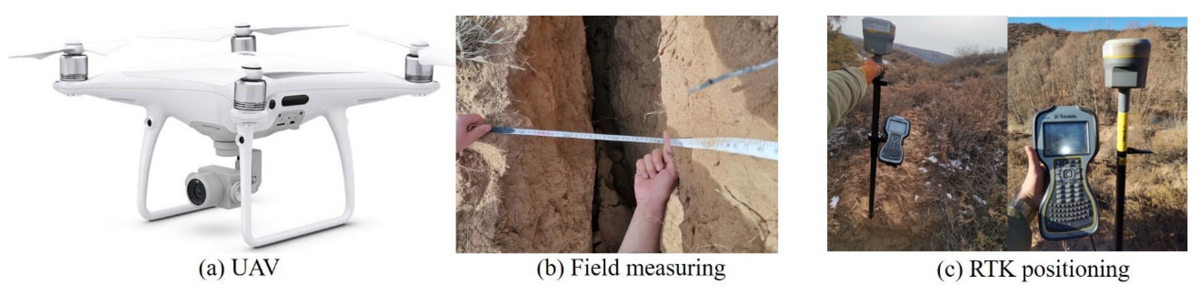
2.2. Monitoring Measures

To accurately grasp the static distribution and dynamic change characteristics of the cracks in the internal and external areas of the working face, the researchers used the GPS-RTK (carrier phase difference technology) positioning + UAV (unmanned aerial vehicle) monitoring + field measuring to carry out the investigation. Each monitoring method is shown in Figure 3. The specific process is as follows: for the static distribution of ground cracks, RTK positioning was used, UAV monitoring was used to determine its location, and ground cracks were mapped; according to the dynamic change characteristics of ground cracks, the RTK was used to record the crack coordinates, and the tape was used to measure the crack width. The UAV used in this study was a PHANTOM 4 PRO equipped with a 1-inch CMOS image sensor. In this photogrammetry, the front overlap was 75%, the side overlap was 60% (calculation of overlap based on formulas (1) and (2)), the flight height was 200 m (calculation of flight height based on formula (3)), the ground resolution was 5.6 cm/pixel, and the image size was 5472 × 3648 pixels. A total of 1024 JPEG images were obtained.
P x = l x L x × 100 %
P y = l y L y × 100 %
H = f × G S D a
where f is the focal length of the objective lens; H is the flight height; GSD is the ground resolution of aerial photography; a is the pixel size; Lx, Ly are the length and width of the entire image, respectively; lx, ly are the length and width of overlapping parts, respectively; Px, Py are the front overlap and side overlap, respectively.

2.3. PFC Numerical Simulation

2.3.1. Principles of Particle Flow Code

PFC, a particle flow code program, simulates the motion and interaction of circular particle media through the discrete element method. In the calculation process of the particle flow code program, the position of particles and the contact force between them constantly update based on the force–displacement law. Newton’s second law determines how each particle moves. The practical problems can be solved by the interaction of the two laws between particles, especially suitable for the simulation calculation of the geotechnical engineering direction [43]. Figure 4 shows the calculation cycle.

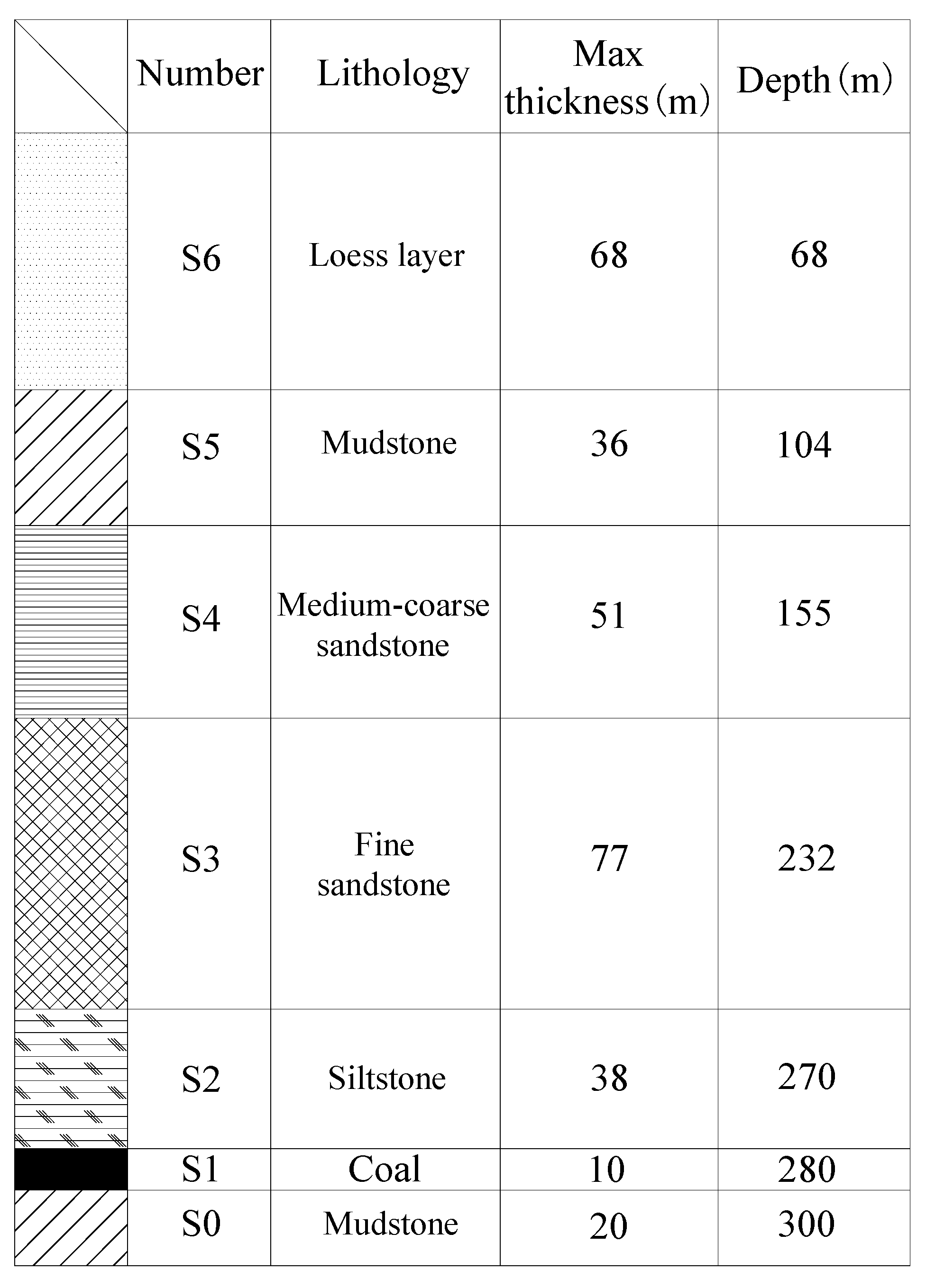
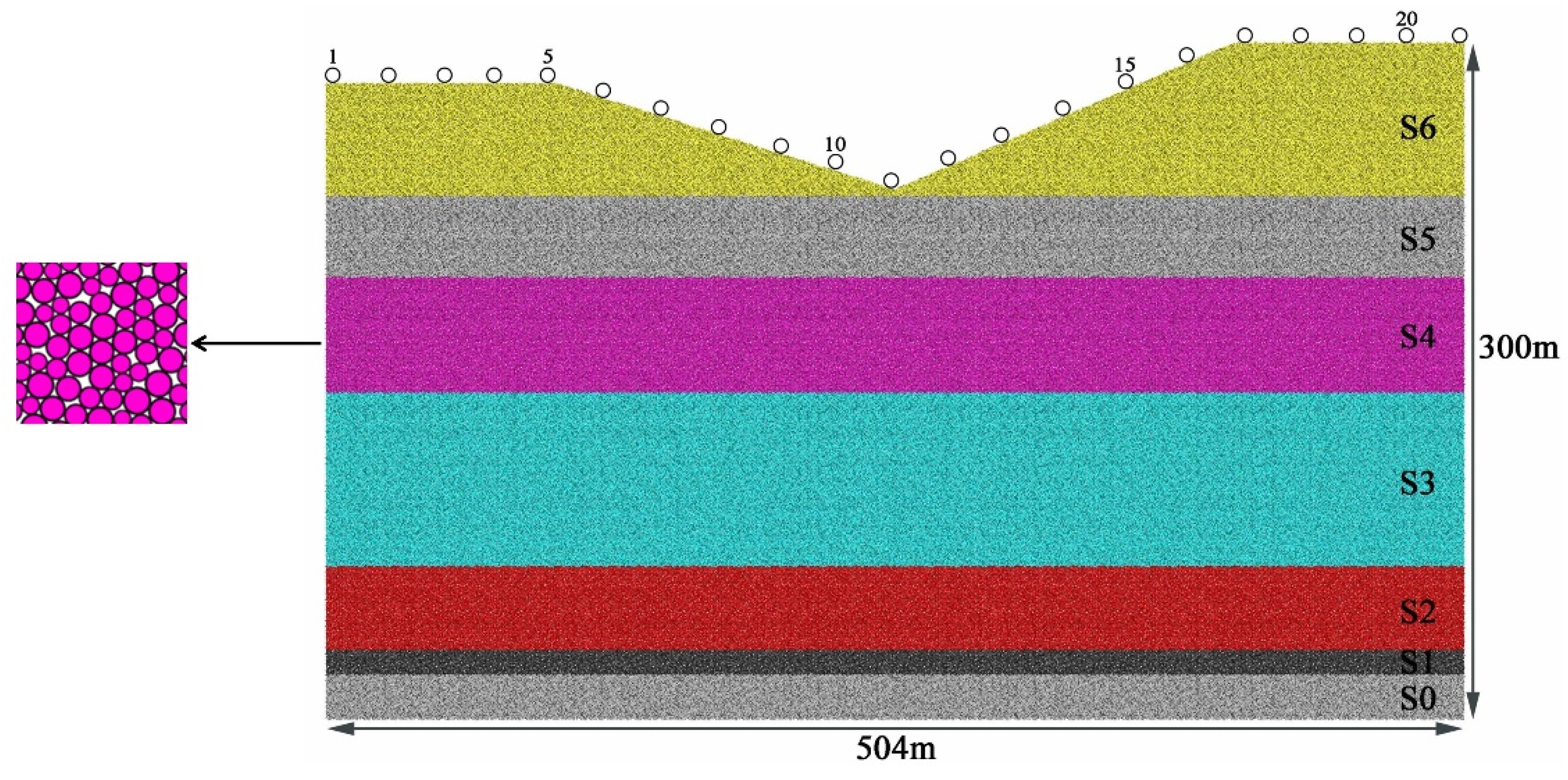
2.3.2. Model Establishment and Parameter Selection

(1)
Model establishment
According to the geometric shape of the working face and the actual survey data, a two-dimensional particle flow mining field model can be established. The maximum size of the model was set to 504 × 300 m2, and the mining direction was simulated by deleting the coal seam corresponding to particles (see Figure 5).
In the process of model calculation, 21 particles at different positions on the surface (loess layer) were real-time monitored (spacing 25 m), and the dynamic changes of these particles were recorded. The distance from the open-off cut from the left boundary of the model was 50 m. The horizontal side displacement of the left and right boundary of the model was constrained. The fixed support condition was applied at the bottom. The upper boundary was free and loaded on the model by gravity (the gravity acceleration was 9.8 m/s2), advancing by 8 m each time. The number of particles was a total of 263,057. The minimum radius of the particle was 30 cm, and the maximum radius ratio of the particle was 1.6.
(2)
Parameter selection
For the selection of the particle contact constitutive model, it is believed that the flat joint model is more suitable for studying the mechanical properties of rock [44]. Therefore, the numerical calculation model in this paper was defined by the flat joint model. The “trial and error method” [45] was used to calibrate the microscopic parameters of the particle flow model, that is, carrying out the uniaxial compression test of the numerical simulation of the rock and soil. By constantly adjusting the microscopic parameters of the model, the macroscopic mechanical properties of the overlying strata were matched with the numerical simulation results. The effective modulus of the flat joint and the rigidity ratio of the flat joint were taken as the relevant microscopic mechanical parameters of different strata. Table 1 shows the microscopic parameters of rock mass calibration in different strata.

3. Results and Analysis

3.1. Static Distribution Characteristics of Ground Cracks

Underground coal mining will cause surface movement and deformation. According to the measured data, the maximum subsidence value of the study area was 6364 mm, and the maximum horizontal movement was 2228 mm. When the coal seam was mined in the gully area, the degree of surface movement and deformation was severe, and the surface damage was serious. The researchers used UAV aerial photography and a field survey to investigate the development of the shape and characteristics of ground cracks in the working face. During the mining of the working face, many step-type and collapse-type cracks appeared near the gully area, which seriously affected the ecological environment, as shown in Figure 6.
According to the distribution of ground cracks, the ground cracks formed by coal seam mining can be divided into boundary cracks (cracks 2–6) and dynamic in-plane cracks (crack 1). The boundary cracks were developed near the open-off cut, stopping line, and flat roadway of the working face. The dynamic in-plane cracks were developed in the working face and were parallel to the open-off cut. A total of 10 boundary cracks and 6 dynamic in-plane cracks were found near the working face. The outermost boundary crack of the stopping line of the working face was 45.6 m away from the stopping line, the outermost boundary crack of the flat roadway was 46.1 m away from the roadway, the outermost boundary crack of the open-off cut was 27.5 m away from the open-off cut, the maximum crack spacing was 18.8 m, and the minimum was 2.2 m. The single crack shape was mainly curved and bent toward the goaf. There was a collapse pit with a maximum diameter of 3 m on one side of the stopping line. The maximum spacing of in-plane cracks was 5.1 m, and the minimum was 2.5 m. The shape of a single crack was mainly linear, as shown in Figure 7.
The proportion of ground crack width and type data in the survey area was calculated to analyze the development degree of ground cracks, as shown in Figure 8. Among the 16 cracks, the number of cracks with a width of 0–0.5 m accounted for 38%, the number of cracks with a width of 0.5 m to 1.5 m accounted for 56%, and the number of cracks with a width greater than 1.5 m accounted for 6%. When the crack width was 0–0.5 m, the number of dynamic in-plane cracks was largest, accounting for 83%; when the crack width was 0.5–1.5 m, the number of boundary cracks was largest, accounting for 89%; when the crack width was greater than 1.5 m, only boundary cracks were developed. The development degree of ground cracks under gully terrain was stronger (the development degree of boundary cracks was greater than that of in-plane cracks), and the width of ground cracks was larger than that in the plain area.

3.2. Dynamic Change Characteristics of Ground Cracks

To accurately grasp the dynamic characteristics of ground cracks, the investigators recorded the width change process of cracks by using the GPS-RTK positioning + field measuring in September, November, and December 2020. The GPS-RTK was used to record the crack coordinates, and the tape was used to measure the crack width, as shown in Figure 3.
As some cracks were located at the bottom of the ditch, only the width changes of cracks 1–3 were counted. According to the observation results, the boundary cracks were in the surface tensile zone, and the crack width changed from small to large and finally tended toward stable. The dynamic in-plane cracks first opened and then closed with the advance of the working face, and the crack width changed from small to large to small and finally tended toward stable, as shown in Figure 9.
Figure 9a shows that the dynamic in-plane crack had a “mountain peak” activity law, that is, the crack width changed from small to large and then became smaller with time. The stable crack width was greater than the initial crack width. This is because crack 1 was located above the slope and had poor closure. The time for the crack width to increase was 8 days, and the time for the crack width to decrease to stable was 4 days, indicating that the period of the width to increase was greater than the period of the width to decrease to stable.
Figure 9b,c shows that the boundary cracks with different initial generation times had similar dynamic development processes, that is, the crack width changed from small to large until stable with time. The stable width of crack 2 outside the stop line was greater than that of crack 3 inside the flat roadway, and the activity time was 12 days.

3.3. Analysis of Numerical Simulation Results

3.3.1. Analysis of Overlying Strata Failure

The numerical model in this paper was a two-dimensional model for simulating coal seam mining. The length of the working face was 301 m, and every 8 m was an advancing stage. When the working face advanced to 296 m (stage 37), the remaining 5 m was a stage. Figure 10 shows the working face advancing diagram.
When the working face advances, the overlying strata will be affected by different degrees of mining deformation. Figure 11 shows the evolution of the overlying strata damage.
In the downhill stage of the gully, when the working face from the open-off cut advanced to 24 m, the immediate roof (S2) collapsed for the first time (Figure 11a). The caving height was 6.2 m and the caving angle was 32.1°. The collapsed rock blocks accumulated on the coal seam floor. At this time, the mining cracks were mainly distributed in the S2 rock strata. As the working face continued to advance, the immediate roof fell with the mining, and the goaf area gradually increased. When the working face advanced to 40 m, the immediate roof collapsed periodically, and the periodic collapse step distance was 8 m (Figure 11b). When the working face advanced to 80 m, due to the load of the loess layer, the rock blocks were continuously crushed and fell into the goaf, and the direct roof (S2) fell to the coal seam floor. At this time, there were obvious longitudinal tension cracks in the gully (Figure 11c). When the working face advanced to 160 m, there were fractured rock pillars due to the step subsidence in the uphill stage of the gully (Figure 11d).
When the working face advanced to 208 m, the pushing mining position was 4 m ahead of the bottom of the gully. The bottom of the gully was subjected to horizontal extrusion on both sides of the slope and the reverse slope, and the uplift phenomenon occurred. The middle rock strata were completely compacted by mining, the deformation of the rock strata extended upward along the slope, and the cracks were formed at the boundary of the goaf (Figure 11e). At the end of simulated mining (advanced to 301 m), the caving span of the overlying strata gradually decreased from the near coal seam to the upward, and the surface finally showed crack failure (Figure 11f).

3.3.2. Analysis of the Development Law of Ground Cracks

When the coal seam was mined in the gully area, both sides of the slope were affected by mining and sliding, and there were ground cracks. Figure 12 shows the development of ground cracks at different advancing distances of the working face. It can be seen from Figure 12 that the development of ground cracks mainly experienced three stages: the initial formation stage, the dynamic development stage, and the gradually stable stage.
(1)
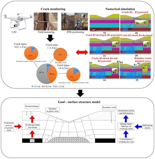
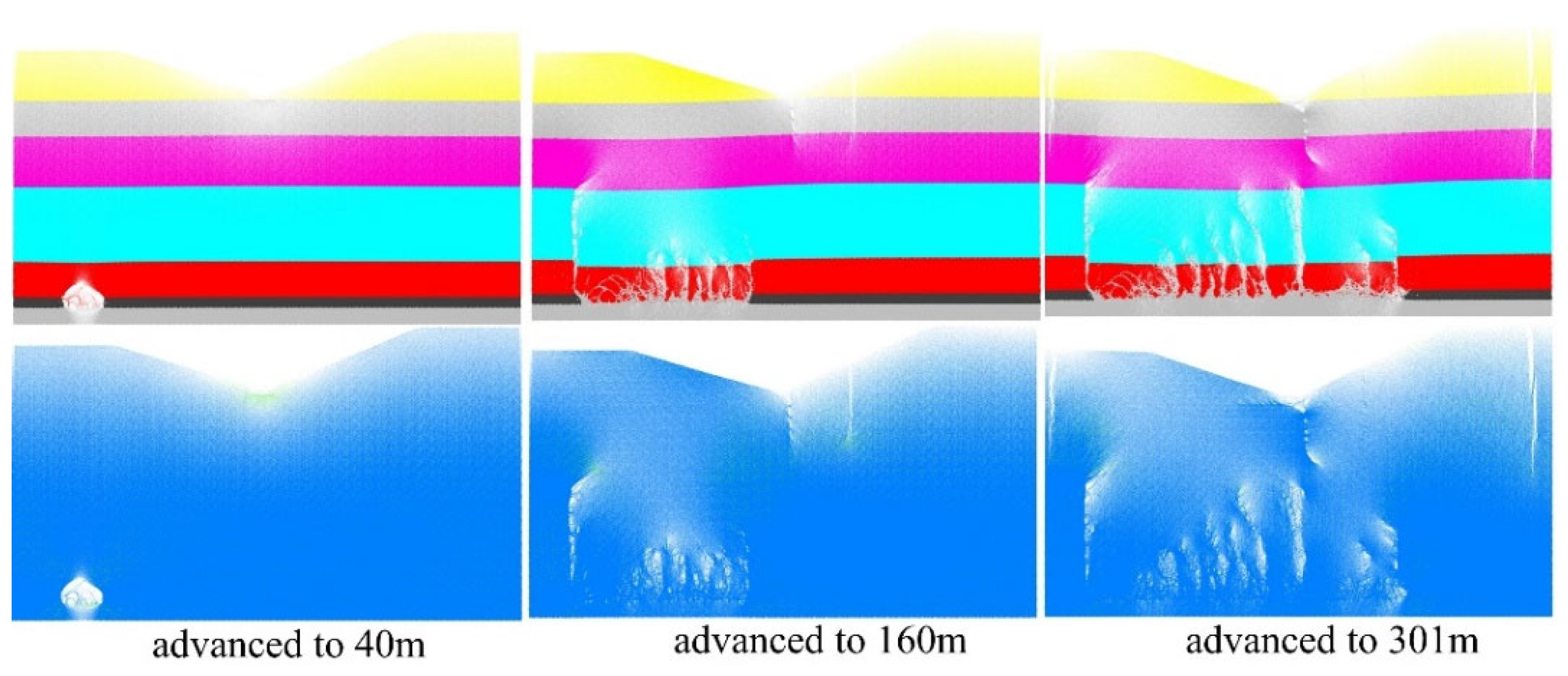
Initial formation period: In the early stage of mining, that is, the downhill stage of the working face, the direct top was not completely collapsed, and the damaged area was small. Although there were cracks around the goaf, they had not yet spread to the surface. The surface movement and deformation of the slope under mining were slight, and there were no cracks. When the working face advanced to 72 m, the slope was damaged. Due to its uneven settlement, tension cracks appeared near the bottom of the ditch. The first crack on the surface was recorded as R1, as shown in Figure 12a,b.
(2)
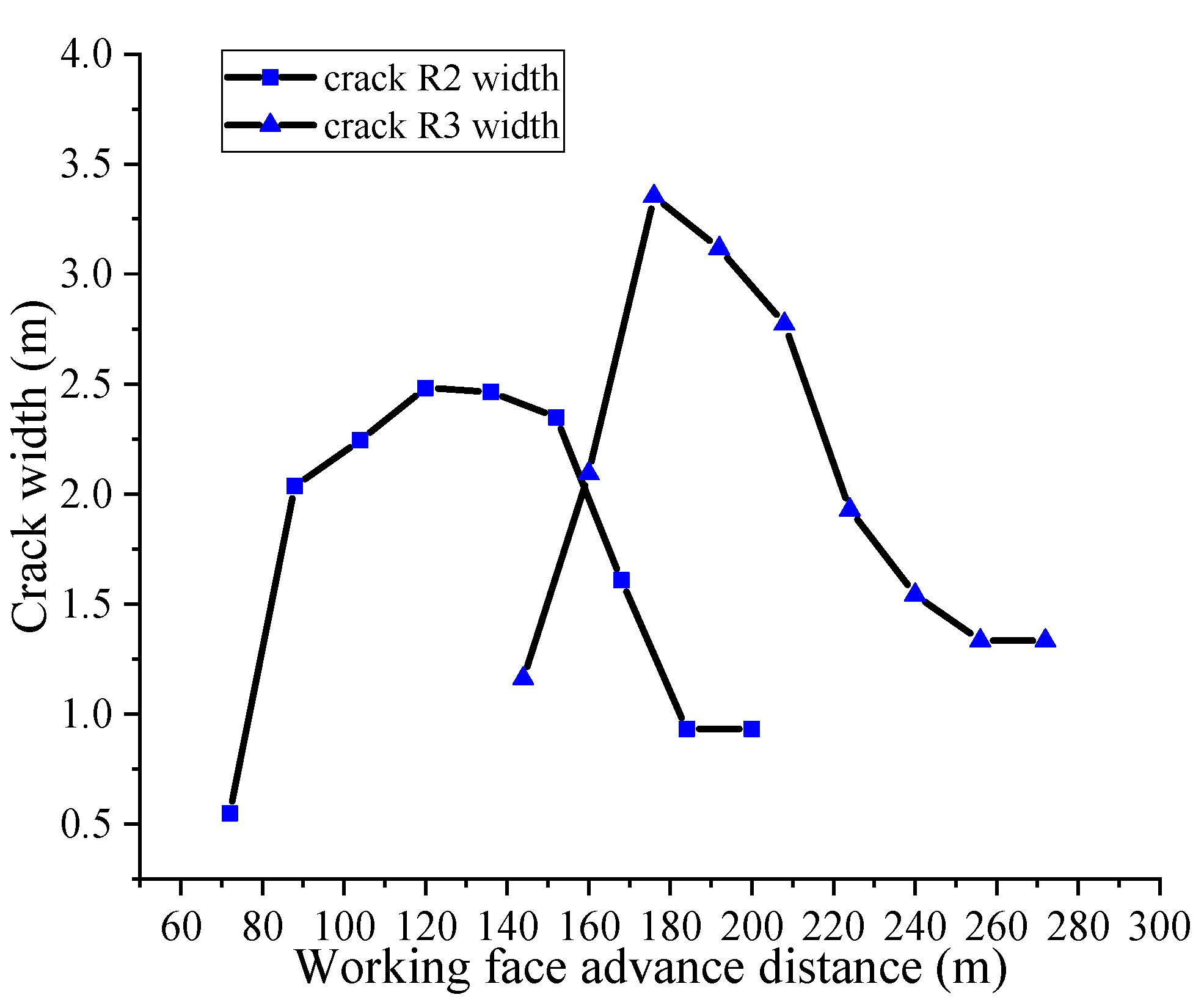
Dynamic development period: As the working face continued advancing, the slope was affected by mining and sliding, and the crack width (R2) increased. When the working face advanced to 144 m, there was crack R3 forming on the surface. Crack R2 gradually closed, and crack R3 continued to develop. When the working face advanced to 208 m, the surface movement and deformation extended upward along the slope, and there were cracks R4 and R5 forming at the boundary of the goaf (on both sides of the slope top position). Then, crack R3 gradually closed, as shown in Figure 12c–e. The stable crack width (R2 and R3) was greater than the initial crack width, which was consistent with the field observation results (Figure 13).
(3)
Gradually stable period: After mining the working face, the cracks under the slope closed, and the slopes on both sides tended toward stable. Finally, cracks R4 and R5 formed at the boundary. Due to the inconsistent slope gradients on both sides, the damage range of the overlying strata was not symmetrical about the gully center, as shown in Figure 12f. The crack R4 angle was 80° and the crack angle was 67.2°.

3.3.3. Analysis of Force Chain Evolution Law

The force chain is a linear chain structure that can connect particles and transfer external loads. The complexity of the force chain network structure represents the macroscopic mechanical behavior between the corresponding particles, which is the basic principle of the force chain [46]. In the process of numerical simulation, the force chain reflects the transfer process of mutual force between broken rocks and the main form of load transfer by the discontinuous medium. Figure 14 shows the development of the force chain in the process of the working face advancing.
In the early stage of mining, a force chain arch structure will form inside the overlying rock, which supports the weight of the overlying strata on the goaf. With the increase in mining size, the range of the force chain arch continued to expand, and the collapse range of overlying strata increased with the enhancement of the force chain arch. At the end of mining, the force chain arch did not develop to the instability state at the top of the slope. If the working face continues mining, the height and span of the force chain arch will further increase. When the arch height exceeded its bearing limit, the arch height stopped developing.
The failure of the force chain arch to bear the load of the overlying strata results in the occurrence of instability and crack. In addition, a large area of bench damage occurs on the surface [42]. According to the above analysis, the development trajectory of the force chain arch can be drawn as an ellipse, as shown in Figure 15. The center of the force chain arch is set as the origin of the coordinate, and the parabolic equation can be established as follows:
x 2 L 0 + y 2 h 0 = 1
where L0 is the advancing distance of working face and h0 is the arch height. The relationship between the advancing distance of the working face and the corresponding force chain arch height is shown in Figure 15b. It can be seen that they satisfy the exponential relationship: h 0 = a e b L 0 (a and b are undetermined coefficients, which are related to the nature of the rock strata in the area). Under the geological mining conditions, a = 12.401 and b = 0.0093, which are substituted into Equation (4) to obtain the trajectory equation of the force chain arch:
x 2 L 0 + y 2 12.401 e 0.0093 L 0 = 1
The force chain arch trajectory equation obtained above can be used to judge the large-scale subsidence damage on the surface when other working faces advance to a certain distance within the scope of the mining field, which can provide a theoretical basis for ground disasters prevention caused by underground coal mining. In conclusion, the force chain arch is the primary bearing capacity system of the overlying strata, which is closely related to surface movement and deformation.

3.3.4. Analysis of Abutment Pressure Variation in Stope

The mining of underground coal seams will cause the redistribution of stress around the goaf, so the change in stope stress can directly reflect the dynamic evolution of the overlying rock structure. Figure 16 shows the relationship between the support pressure of the numerical model and the different mining distances of the coal seam. The measurement circle was arranged on the coal seam floor from the open-off cut to both sides. When the coal seam was mined, the increased area of abutment pressure was located in the front and rear of the goaf, and the increased scope of tensile stress was located right above the goaf. With the continuous advancement of the working face, the maximum abutment pressure values in the front and rear of the goaf gradually increased, and the position continuously moved to the front of the working face. When the working face advanced to 40 m, the maximum abutment pressure of all monitoring points was 8.55 MPa. After that, the working face collapsed periodically, and the change in supporting stress of surrounding rock in the goaf was relatively complex compared with that in the coal body. The peak value of supporting pressure showed a slowly increasing trend, and the position was always located in the rear coal body of the working face. After the working face was mined, the maximum supporting pressure of all monitoring points was 11.2 MPa.

4. Discussion

4.1. Characteristics of Mining-Induced Ground Cracks under Gully Terrain

The shape of cracks based on field investigation shows that ground cracks of the loess-gully under the influence of mining have the following characteristics:
(1)
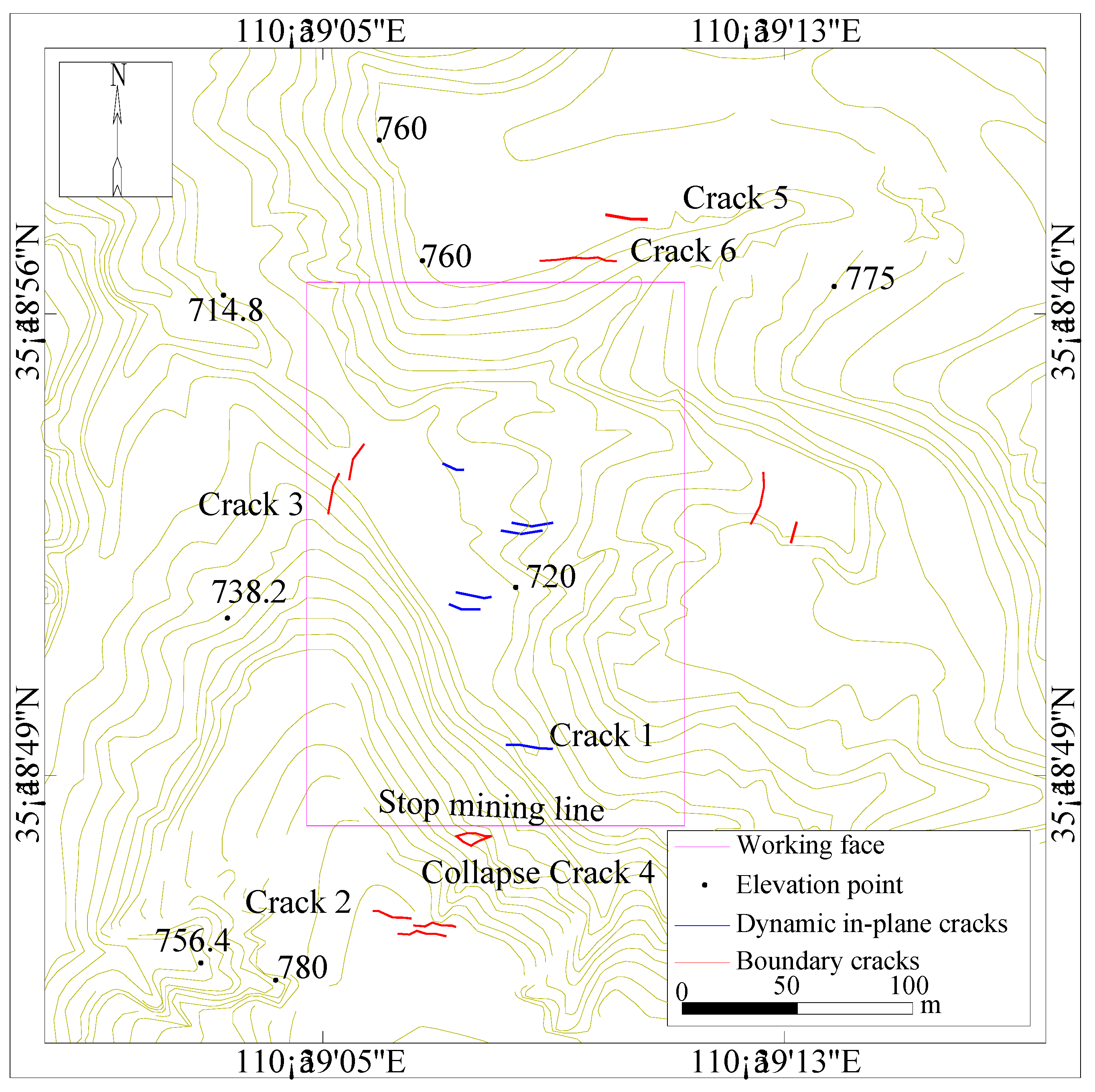
The location of crack development: The distribution of ground cracks in the working face is shown in Figure 7. The ground cracks mainly concentrated in the internal scope of the working face and the boundary of the goaf. The extension length ranged from a few meters to tens of meters, and the extension width range a few centimeters to several meters. The boundary cracks were mainly distributed on both sides of the gully slope top and the flat roadway boundary, which were mainly in an arc shape and generally parallel to the goaf boundary. The dynamic in-plane cracks were distributed near the bottom of the gully and both sides of the slope, mostly in a straight line, and the extension direction of the dynamic in-plane cracks was generally perpendicular to the mining direction of the working face.
(2)
The obvious step cracks: The ground cracks were mainly the step cracks and collapse cracks. The vertical opening scale or horizontal opening scale of step cracks was large, and the failure range of collapse cracks was large. The formation of ground cracks was closely related to the structure and lithology of overlying strata. Due to the overall collapse of overlying strata after the breaking of the basic roof, the cracks above the goaf spread to the surface, leading to the lateral cracking of the surface soil, the longitudinal subsidence, and the emergence of steps.
(3)
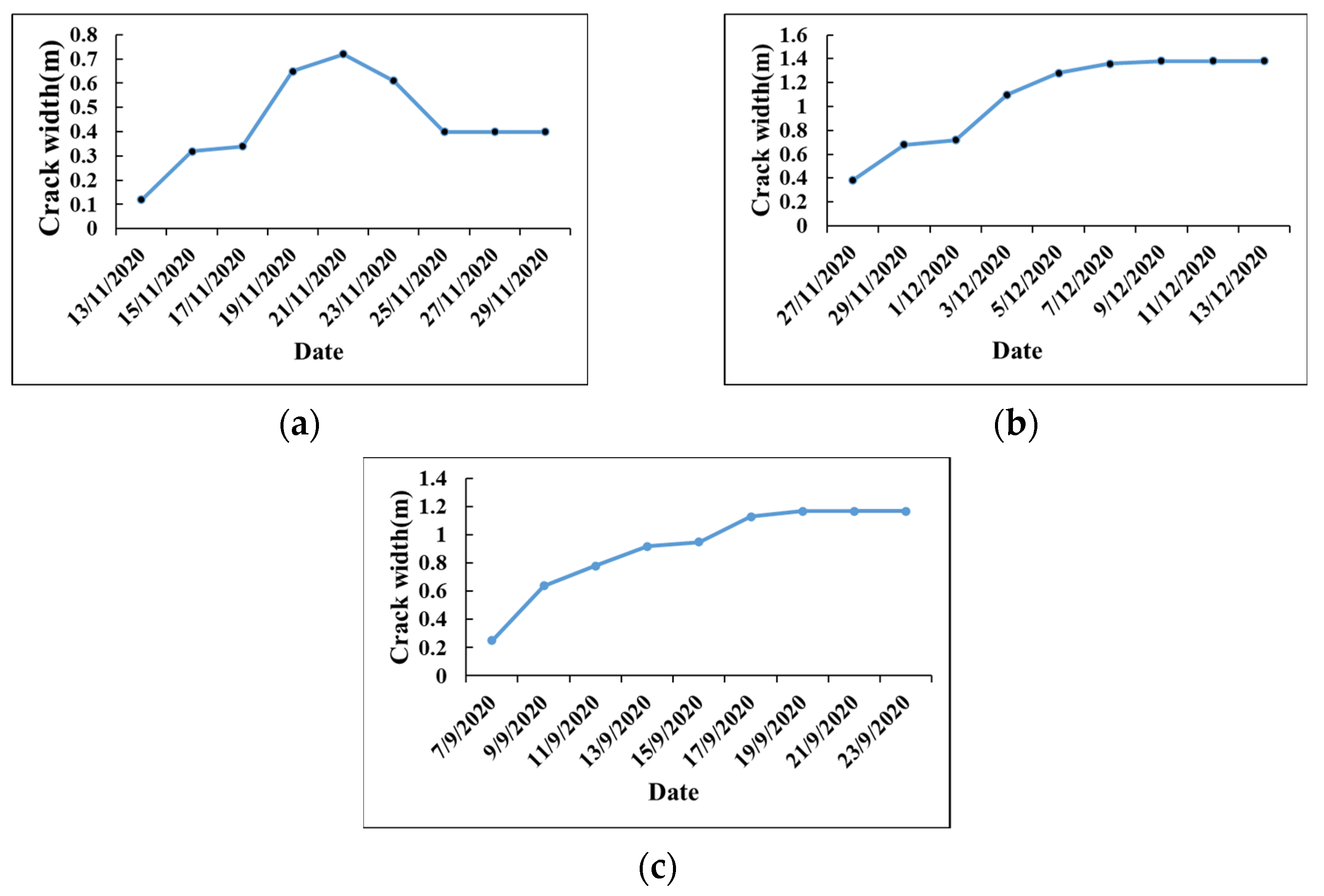
The dynamic closure: The size of ground cracks had dynamic changes with coal seam mining. When the working face advanced to a certain distance, the dynamic in-plane crack width gradually reduced and became stable, showing closure. Affected by the coal seam goaf on both sides of the slope and topography, the closure of the cracks was lower than that of the cracks generated under the plain terrain (see Figure 6a; although crack 1 was located above the slope, it was not completely closed after the mining of the working face). However, the cracking degree of the cracks on top of the slope increased (see Figure 6b; crack 2 was located above the slope top, and the damage was more serious), and the direction of cracking tended to the free face.

4.2. Formation Process of Ground Cracks

In the coal mining under the gully, the destruction of overlying strata experienced the process: the first collapse of the direct roof–the periodic collapse–the complete collapse. When the working face advanced to the bottom of the gully, the bottom of the gully would be uplifted under horizontal compression. At the end of the mining, it can be seen that the caving span of the overlying strata gradually decreased from the near coal seam to the upward, and the ground suffered from cracks.
After the coal seam is mined, the overlying strata and the surface will move and deform. Ground cracks will occur when the surface soil layer exceeds its plastic deformation limit. If the ground cracks are connected with the underground, it easily causes mine water inrush accidents. Therefore, the formation of ground cracks is a dynamic development process from bottom to top, namely “coal mining–overlying strata movement–surface deformation–ground cracks”. Among them, the main factors affecting the development of ground cracks are the coal thickness, working face size, mining depth, and overlying strata lithology. To more intuitively analyze the formation mechanism of ground cracks, we established a “goaf–surface” structure model, as shown in Figure 17.

4.3. Comparison of Different Methods to Study Ground Cracks

Dai et al. [47] used similar material simulation experiments to study the law of surface movement and deformation in mountainous areas. It is clear that when the underground coal seam was mined in mountainous areas (single slope), the upward slope direction was stretched, and the downward slope direction was compressed on the surface above the coal pillar (goaf boundary and outside). Therefore, two cracks appeared in the middle and top of the slope, which were narrow and had the same shape, as shown in Figure 18. For coal seam mining in the gully terrain (V-type slope), the slope was affected by slip and mining, and many cracks formed near the bottom of the gully, the middle of the slope, and the outside of the top of the slope. Because the slope of the right slope was larger than that of the left slope, the surface was affected seriously by slip, and the back slope mining was more likely to produce cracks. Therefore, the cracks were primarily located on the right slope, and the final cracks developed to the depth of the bedrock.
Hou et al. [48] used the particle flow method to simulate the development characteristics of ground cracks caused by shallow coal seam mining. The parallel bond model was defined as a constitutive model, which was not suitable for studying the geotechnical engineering problems. Unlike the existing current results, a flat joint model closer to the mechanical properties of rock was selected to establish a numerical model. Meanwhile, we summarized the development stages of ground cracks and classified them.
Many scholars used elastic mechanics, statistics, and mining subsidence theory to explain the development law of ground cracks without considering the interaction between rock particles [49,50]. Unlike the current research results, based on the chain structure between particles, this paper considered that there was a force chain arch structure forming inside the overlying strata in the process of coal seam mining. It undertook the weight of the overlying rock on the goaf and developed with the expansion of mining size. According to the development law of the force chain, the trajectory equation of the force chain arch was established, which can provide a theoretical basis for preventing ground disasters caused by underground coal mining.
In this paper, the researchers obtained the same conclusion through field measurement and numerical simulation: the cracks development stage has stages by coal mining under gully terrain. Because the slope on both sides is affected by the mining and slipping, the closure of the dynamic in-plane cracks will be reduced, and the crack width when it is stable is greater than the initial crack width, which is different from the conclusion of coal mining under the plain area or single slope terrain.
The study on the development law of mining ground cracks under other special terrain (double gullies terrain) will be continued in the future.

5. Conclusions

(1)
The development degree of mining-induced ground cracks under gully terrain is strong. The number of cracks with a width of 0–0.5 m accounts for 38%, the number of cracks with a width of 0.5 m to 1.5 m accounts for 56%, and the number of cracks with a width greater than 1.5 m accounts for 6%. Combined with field investigation and numerical simulation results, the ground cracks can be divided into dynamic in-plane cracks (in the working face and parallel to the open-off cut) and boundary cracks (near the stop line, open-off cut, and roadway).
(2)
The dynamic in-plane cracks have the activity law of “mountain peak”, and the crack width shows the variation characteristics of “opening first and closing later”. The activity time is 12 days. The slopes on both sides are affected by mining and sliding, and the closure of the cracks will be reduced. The stable crack width is greater than the initial crack width. The width of the boundary crack shows the variation characteristics of “only opening and not closing”, and the activity time is 12 days.
(3)
The development process of the cracks experiences three stages: the initial formation stage, the dynamic development stage, and the gradual stable stage. Based on the chain structure between particles, this paper holds that in the process of coal seam mining, the force chain arch structure is formed inside the overlying strata, which is the primary bearing capacity system of the overlying strata, and its development state is closely related to the ground cracks.
(4)
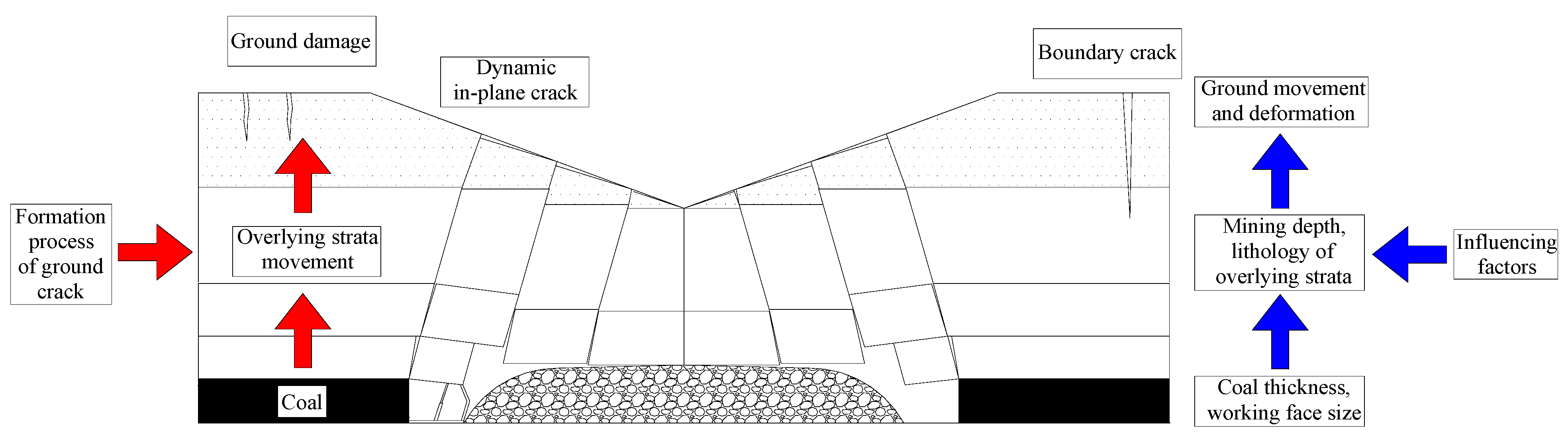
The formation of ground cracks is a dynamic development process from bottom to top, namely “coal mining–overlying strata movement–surface deformation–ground cracks”. In this paper, a “goaf–surface” structure model is established to intuitively analyze the formation mechanism and influencing factors of ground cracks.

Author Contributions

Methodology, X.L.; Formal analysis, Y.Y.; Investigation, Y.Z. (Yuanhao Zhu); Resources, H.D.; Writing—original draft, Y.Z. (Yanjun Zhang). All authors have read and agreed to the published version of the manuscript.

Funding

This research was supported by the National Natural Science Foundation of China, grant number (51404272, Y.Y.); the Fundamental Research Funds for the Central Universities, grant number (2022YJSDC20, Y.Y.). The APC was funded by (2022YJSDC20).

Conflicts of Interest

The authors declare that they have no competing interests.

References

  1. Brodny, J.; Tutak, M. Analysing the Utilisation Effectiveness of Mining Machines Using Independent Data Acquisition Systems: A Case Study. Energies 2019, 12, 2505. [Google Scholar] [CrossRef] [Green Version]
  2. Cicmanec, P.; Hrabovsky, J.; Durove, J.B. Mechanized Mining of Might Coal Seams into Complicated Geological and Underground Conditions. Gospod. Surowcami Miner. 2008, 24, 37–47. [Google Scholar]
  3. Kratzsch, H. Mining Subsidence Engineering; Springer: Berlin/Heidelberg, Germany, 1983. [Google Scholar]
  4. Zhang, Y.; Kong, J.; Long, S.; Zhu, Y.; Zhu, W.; Wu, T. Study on the Ground Fissure Development Law of Coal Mining Based on UAV Photogrammetry and the Particle Flow Theory. Front. Environ. Sci. 2022, 10, 915645. [Google Scholar] [CrossRef]
  5. Wang, R.; Wu, K.; He, Q.; He, Y.; Gu, Y.; Wu, S. A Novel Method of Monitoring Surface Subsidence Law Based on Probability Integral Model Combined with Active and Passive Remote Sensing Data. Remote Sens. 2022, 14, 299. [Google Scholar] [CrossRef]
  6. Li, G.; Wan, Y.; Guo, J.; Ma, F.; Zhao, H.; Li, Z. A Case Study on Ground Subsidence and Backfill Deformation Induced by Multi-Stage Filling Mining in a Steeply Inclined Ore Body. Remote Sens. 2022, 14, 4555. [Google Scholar] [CrossRef]
  7. Yan, Y.; Zhang, Y.; Zhu, Y.; Cai, J.; Wang, J. Quantitative Study on the Law of Surface Subsidence Zoning in Steeply Inclined Extra-Thick Coal Seam Mining. Sustainability 2022, 14, 6758. [Google Scholar] [CrossRef]
  8. Dulias, R. The Impact of Mining on the Landscape: A Study of the Upper Silesian Coal Basin in Poland; Environmental Science and Engineering; Springer International Publishing: Cham, Switzerland, 2016; p. 209. [Google Scholar]
  9. Marschalko, M.; Yilmaz, I.; Kfistkova, V.; Fuka, M.; Kubecka, K.; Bouchal, T. An indicative method for determination of the mosthazardous changes in slopes of the subsidence basins in underground coal mining area in Ostrava (Czech Republic). Environ. Monit. Assess. 2013, 185, 509–522. [Google Scholar] [CrossRef] [PubMed]
  10. Wang, J.; Wang, P.; Qin, Q.; Wang, H. The effects of land subsidence and rehabilitation on soil hydraulic properties in a mining area in the loess plateau of china. CATENA 2017, 159, 51–59. [Google Scholar] [CrossRef]
  11. Xu, Y.K.; Wu, K.; Li, L.; Zhou, D.W.; Hu, Z.Q. Ground cracks development and characteristics of strata movement under fast excavation: A case study at Bulianta coal mine, China. Bull. Eng. Geol. Environ. 2019, 78, 325–340. [Google Scholar] [CrossRef]
  12. Henselowsky, F.; Rlkens, J.; Kelterbaum, D.; Bubenzer, O. Anthropogenic relief changes in a long-lasting lignite mining area (“ville”, Germany) derived from historic maps and digital elevation models. Earth Surf. Process. Landf. 2021, 46, 1725–1738. [Google Scholar] [CrossRef]
  13. Harnischmacher, S.; Zepp, H. Mining and its impact on the earth surface in the Ruhr district (Germany). Z. Geomorphol. Suppl. Issues 2014, 58, 3–22. [Google Scholar] [CrossRef]
  14. Solarski, M. Anthropogenic transformations of the bytom area relief in the period of 1883–1994. Environ. Socio-Econ. Stud. 2013, 1, 1–8. [Google Scholar] [CrossRef]
  15. Nadudvari, A. Using radar interferometry and SBAS technique to detect surface subsidence relating to coal mining in Upper Silesia from 1993–2000 and 2003–2010. Environ. Socio-Econ. Stud. 2016, 4, 24–34. [Google Scholar] [CrossRef] [Green Version]
  16. Hejmanowski, R.; Malinowska, A.A. The Impact of Deep Underground Coal Mining on Earth Fissure Occurrence. Acta Geodyn. Geomater. 2016, 13, 321–330. [Google Scholar]
  17. Malinowska, A.A.; Misa, R.; Tajdus, K. Geomechanical modeling of subsidence related strains causing earth fissures. Acta Geodyn. Geomater. 2018, 15, 197–204. [Google Scholar] [CrossRef] [Green Version]
  18. Lee, D.K.; Mojtabai, N.; Lee, H.B.; Song, W.K. Assessment of the influencing factors on subsidence at abandoned coal mines in south korea. Environ. Earth Sci. 2013, 68, 647–654. [Google Scholar] [CrossRef]
  19. Deb, D.; Choi, S.O. Analysis of sinkhole occurrences over abandoned mines using fuzzy reasoningm: A case study. Geotech. Geol. Eng. 2006, 24, 1243–1258. [Google Scholar] [CrossRef]
  20. Akcin, H.; Kutoglu, H.S.; Kemaldere, H.; Deguchi, T.; Koksal, E. Monitoring subsidence effects in the urban area of Zonguldak Hardcoal Basin of Turkey by InSAR-GIS integration. Nat. Hazards Earth Syst. Sci. 2010, 10, 1807–1814. [Google Scholar] [CrossRef]
  21. Genis, M.; Akn, H.; Aydan, M.; Bacak, G. Investigation of possible causes of sinkhole incident at the Zonguldak coal basin, turkey. Geomech. Eng. 2018, 16, 177–185. [Google Scholar]
  22. Ghosh, G.K.; Sivakumar, C. Application of underground microseismic monitoring for ground failure and secure longwall coal mining operation: A case study in an Indian mine. J. Appl. Geophys. 2018, 150, 21–39. [Google Scholar] [CrossRef]
  23. Tiwari, A.; Narayan, A.B.; Dwivedi, R.; Swadeshi, A.; Pasari, S.; Dikshit, O. Geodetic investigation of landslides and land subsidence: Case study of the Bhurkunda coal mines and the Sirobagarh landslide. Surv. Rev. 2018, 52, 134–149. [Google Scholar] [CrossRef]
  24. Li, Q.; Zhang, Y.; Zhao, Y.; Zhu, Y.; Yan, Y. Study on Stability Discrimination Technology of Stope Arch Structure. Sustainability 2022, 14, 11082. [Google Scholar] [CrossRef]
  25. Tudor, G.; Catalin, N.M.; Camelia, B.; Diana, M. Impacts of mining activities on surface deformation. In Proceedings of the International Multidisciplinary Scientific GeoConference Surveying Geology and Mining Ecology Management—SGEM, Florence, Italy, 23–26 October 2018; Volume 18, pp. 489–495. [Google Scholar]
  26. Liu, H.; He, C.G.; Deng, K.Z.; Bian, Z.F.; Fan, H.D. Analysis of Forming Mechanism of Collapsing Ground Fissure Caused by Mining. J. Min. Saf. Eng. 2013, 30, 380–384. [Google Scholar]
  27. Che, X.Y.; Hou, E.K.; Sun, X.Y.; Jiang, Y.Q.; Xie, X.S. Research on Overburden Breaking Characteristics and Ground Crack Formation Mechanism of Shallow Coal Seam Under the Gully. J. Xi’an Univ. Sci. Technol. 2021, 41, 104–111. [Google Scholar]
  28. Liu, H.; Deng, K.Z.; Lei, S.G.; Bian, Z.F.; Chen, D.Y. Dynamic Developing Law and Governance Standard of Ground Fissures Caused by Underground Mining. J. Min. Saf. Eng. 2017, 34, 884–890. [Google Scholar]
  29. Pilecka, E.; Szwarkowski, D. An Application of the Ground Laser Scanning to Recognise Terrain Surface Deformation over a Shallowly Located Underground Excavation. E3S Web Conf. 2017, 24, 01006. [Google Scholar] [CrossRef]
  30. Kang, J.R. Analysis of Effect of Fissures Caused by Underground Mining on Ground Movement and Deformation. Chin. J. Rock Mech. Eng. 2008, 27, 59–64. [Google Scholar]
  31. He, W.L.; Kang, J.R. Laws of Ground Movement and Deformation in Mountainous Areas. J. China Coal Soc. 1992, 17, 1–15. [Google Scholar]
  32. Hu, Z.Q.; Wang, X.J.; He, A.M. Distribution characteristic and development rules of ground fissures due to coal mining in windy and sandy region. J. China Coal Soc. 2014, 39, 11–18. [Google Scholar]
  33. Xu, J.L.; Zhu, W.B.; Wang, X.Z.; Zhang, Z.Q. Influencing Mechanism of Gully Terrain on Ground Pressure Behaviors in Shallow Seam Longwall Mining. J. China Coal Soc. 2012, 37, 179–185. [Google Scholar]
  34. Zhang, Z.Q.; Xu, J.L.; Liu, H.L.; Li, H.W. Influencing Laws Study of Depth of Gully on Dynamic Strata Pressure of Working Face in Shallow Coal Seams. J. Min. Saf. Eng. 2013, 30, 501–505. [Google Scholar]
  35. Li, J.W.; Liu, C.A.; Zhao, J.; Wang, W.C.; Bu, Q.W. Study on Occurrence Mechanism and Control Technology of Mining-induced Strata Pressure in Shallow Depth Coal Seams of Valley Region. Coal Sci. Technol. 2018, 46, 104–110. [Google Scholar]
  36. Zhao, J.; Liu, C.A.; Li, J.W. Overburden Failure and Strata Pressure Behavior Characteristics Under Condition of Shallow Coal Seam in Gully Terrain. Coal Sci. Technol. 2017, 45, 34–40. [Google Scholar]
  37. Zhao, J.; Liu, C.A.; Li, J.W. Three-dimensional Geological Modeling and Surface Damage in Gully Area Due to Shallow Coal Seam Mining. J. Min. Saf. Eng. 2018, 35, 97–105. [Google Scholar]
  38. Liu, H.; Liu, X.Y.; Deng, K.Z.; Lei, S.G.; Bian, Z.F. Developing Law of Sliding Ground Fissures Based on Numerical Simulation Using UDEC. J. China Coal Soc. 2016, 41, 625–632. [Google Scholar]
  39. Salmi, E.F.; Nazem, M.; Karakus, M. Numerical Analysis of a Large Landslide Induced by Coal Mining Subsidence. Eng. Geol. 2017, 217, 141–152. [Google Scholar] [CrossRef]
  40. Trong, N.D.; Wu, J.H. Simulating a Mining-triggered Rock Avalanche Using DDA, a Case Study in Nattai North Australia. Eng. Geol. 2019, 264, 105386. [Google Scholar]
  41. Wang, C.L.; Zhang, C.S.; Zhao, X.D.; Liao, L.; Zhang, S.L. Dynamic Structural Evolution of Overlying Strata During Shallow Coal Seam Longwall Mining. Int. J. Rock Mech. Min. Sci. 2018, 103, 20–32. [Google Scholar] [CrossRef]
  42. Zhang, Y.; Yan, Y.; Dai, H.; Zhu, Y.; Wu, T. Stability and force chain characteristics of “inclined step cutting body” in stope. Appl. Sci. 2021, 11, 10276. [Google Scholar] [CrossRef]
  43. Zhou, J.; Chi, Y.; Chi, Y.W.; Xu, J.P. The Method of Particle Flow and PFC2D Code. Rock Soil Mech. 2000, 21, 271–274. [Google Scholar]
  44. Chen, P.Y. Research Progress on Pfc2d Simulation of Crack Propagation Characteristics of Cracked Rock. J. Eng. Geol. 2018, 124, 253–264. [Google Scholar]
  45. Lee, H.; Jeon, S. An Experimental and Numerical Study of Fracture Coalescence in Pre-cracked Specimens Under Uniaxial Compression International. J. Solids Struct. 2011, 48, 979–999. [Google Scholar] [CrossRef]
  46. Sun, Q.C.; Wang, G.Q. Review on Granular Flow Dynamics and Its Discrete Element Method. Adv. Mech. 2008, 38, 87–100. [Google Scholar]
  47. Dai, H.Y.; Zhai, J.C.; Hu, Y.J. Testing Study on Surface Displacement of Mountainous Region with Similar Material Chinese. J. Rock Mech. Eng. 2000, 19, 501–504. [Google Scholar]
  48. Hou, E.K.; Cong, T.; Xie, X.S.; Wei, J.B. Ground surface fracture development characteristics of shallow double coal seam staggered mining based on particle flow. J. Min. Strata Control Eng. 2020, 2, 013521. [Google Scholar]
  49. Cai, M.F. Key theories and technologies for surrounding rock stability and ground control in deep mining. J. Min. Strata Control Eng. 2020, 2, 033037. [Google Scholar]
  50. Hu, Q.F.; Cui, X.M.; Liu, W.K.; Ma, T.J.; Geng, H.R. Law of overburden and surface movement and deformation due to mining super thick coal seam. J. Min. Strata Control Eng. 2020, 2, 023021. [Google Scholar]
Figure 1. Geographical location of the study area.
Remotesensing 14 05985 g001
Figure 2. Drill hole columnar section.
Remotesensing 14 05985 g002
Figure 3. Monitoring measures.
Remotesensing 14 05985 g003
Figure 4. Calculation cycle process of particle flow code (PFC).
Remotesensing 14 05985 g004
Figure 5. Particle flow field model.
Remotesensing 14 05985 g005
Figure 6. Ground cracks. (a) Crack 1, (b) Crack 2, (c) Crack 3, (d) Crack 4, (e) Crack 5, (f) Crack 6.
Remotesensing 14 05985 g006
Figure 7. Distribution of ground cracks.
Remotesensing 14 05985 g007
Figure 8. Width ratio of different types of cracks.
Remotesensing 14 05985 g008
Figure 9. Dynamic variation characteristics of cracks. (a) Crack 1, (b) Crack 2, (c) Crack 3.
Remotesensing 14 05985 g009
Figure 10. Working face advancing process.
Remotesensing 14 05985 g010
Figure 11. Overlying strata collapse evolution. (a) Advanced to 24 m, (b) advanced to 40 m, (c) advanced to 80 m, (d) advanced to 160 m, (e) advanced to 208 m, and (f) advanced to 301 m.
Remotesensing 14 05985 g011
Figure 12. Dynamic development of cracks caused by mining. (a) Advanced to 24 m, (b) advanced to 72 m, (c) advanced to 144 m, (d) advanced to 176 m, (e) advanced to 208 m, and (f) advanced to 301 m.
Remotesensing 14 05985 g012
Figure 13. Variations in width cracks R2–3 with advancing working face.
Remotesensing 14 05985 g013
Figure 14. Numerical simulation of evolution of force chain.
Remotesensing 14 05985 g014
Figure 15. Curve track and height relation diagram of force chain arch. (a) Curve track of force chain arch, (b) Arch height relationship of force chain.
Remotesensing 14 05985 g015
Figure 16. Distribution of abutment pressure of basic roof with different propulsion distances.
Remotesensing 14 05985 g016
Figure 17. Goaf—surface structure model.
Remotesensing 14 05985 g017
Figure 18. Cracks in soli and rock.
Remotesensing 14 05985 g018
Table 1. Micromechanical parameters of overlying strata.
DescriptionLoess LayerMudstoneMedium-Coarse SandstoneFine SandstoneSiltstoneCoalMudstone
Volume-weight18242524241424
Minimum radius of particles30303030303030
Particle Radius Ratio1.61.61.61.61.61.61.6
Effective modulus of flat joint0.413.2181626.4413.2
Rigidity ratio of flat joint2222222
Average tensile strength and standard deviation of flat joints0.1/0.0250.8/0.21.1/0.2751/0.251.2/0.30.25/0.06250.8/0.2
Average cohesion and standard deviation of flat joints4/120/520/520/520/510/2.520/5
Publisher’s Note: MDPI stays neutral with regard to jurisdictional claims in published maps and institutional affiliations.

