Article

Assessment of IRNSS-Only Data Processing: Availability, Single-Frequency SPP and Short-Baseline RTK

1
School of Geosciences and Info-Physics, Central South University, Changsha 410083, China
2
State Key Laboratory of Geo-Information Engineering, Xi’an 710054, China
*
Author to whom correspondence should be addressed.
Remote Sens. 2022, 14(10), 2462; https://doi.org/10.3390/rs14102462
Submission received: 16 April 2022 / Revised: 16 May 2022 / Accepted: 19 May 2022 / Published: 20 May 2022
(This article belongs to the Special Issue GNSS Precise Positioning and Geoscience Application)

Abstract

:
The Indian Regional Navigation Satellite System (IRNSS) currently can provide independent positioning services with eight in-orbit satellites. This study provides a comprehensive assessment of IRNSS-only data processing, including the availability of satellite constellation, the performance of single-frequency single point positioning (SPP), and the performance of single-frequency short-baseline real-time kinematic (RTK) positioning. Regarding the availability of IRNSS-only case in its primary service areas, the average number of visible satellites is 6–8, and the average Position Dilution of Precision (PDOP) value falls between 3.3 and 6.2, under a service rate of nearly 100.0%. The datasets from 14 stations located in the IRNSS service areas spanning a week are used for position determination. The results show that under the IRNSS single-system case, the positioning accuracy of the SPP is 6.031, 6.015, and 9.668 m in the east, north, and up directions, respectively, and the mean positioning bias of short-baseline RTK is 5.4, −21.1, and −0.2 mm with a standard deviation (STD) error of 7.8, 19.2, and 29.0 mm in the three directions, respectively. For comparative analysis, the results of the GPS single-system and GPS/IRNSS dual-system combination cases are also presented. The positioning performance of IRNSS is inferior to that of GPS, and the performance improvement of GPS/IRNSS dual-system integrated solutions over GPS single-system solutions is not significant. Furthermore, based on the GPS/IRNSS dual-system solutions, the inter-system bias estimates from SPP, the code observation residuals from SPP, and the carrier phase observation residuals from short-baseline RTK are characterized.

Graphical Abstract

1. Introduction

The Indian Regional Navigation Satellite System (IRNSS) is developed by the Indian Space Research Organisation and officially named Navigation with Indian Constellation (NavIC). IRNSS broadcasts satellite signals through the L5 (1176.45 MHz) and S (2492.028 MHz) carriers. Currently, IRNSS has eight satellites that entered the orbit, including three geostationary earth orbit (GEO) satellites (I03, I06, and I07) and five inclined geosynchronous orbit (IGSO) satellites (I01, I02, I04, I05, and I09) [
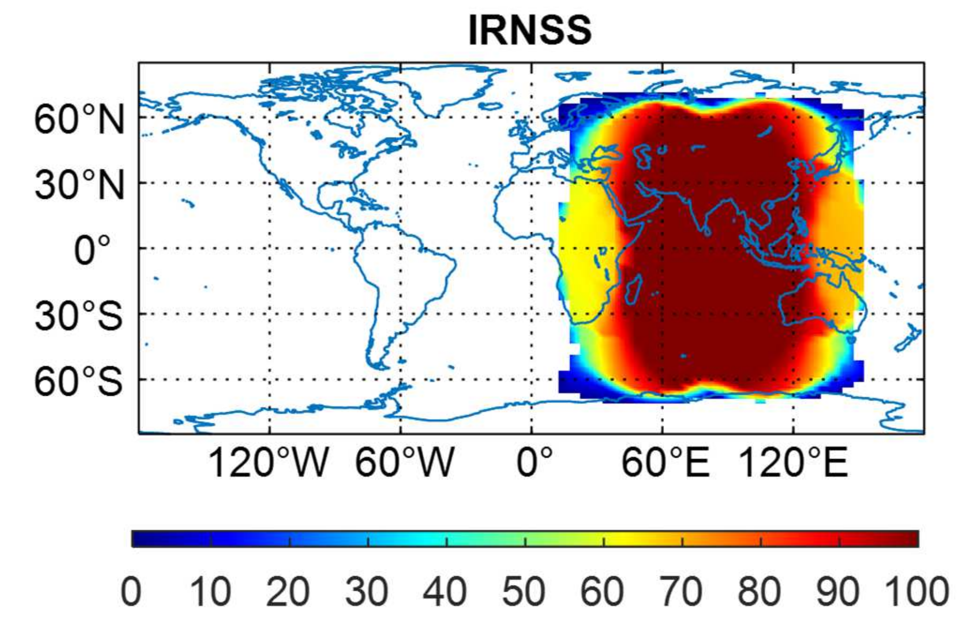
1]. IRNSS is committed to providing an independent positioning service over India and its surrounding areas. The Indian continent and the area within 1500 km from its boundary are the primary service areas, and the areas between 30° S and 50° N and between 30° E and 130° E are the secondary service areas.
Several researchers have conducted the assessment of IRNSS signal quality. Mukesh et al. [2] systematically assessed the carrier-to-noise density ratio (C/N0) of IRNSS, and reported that the C/N0 of seven satellites (I01–I07) varied in the range of 30–45, 44–54, 50–55, 41–53, 45–53, 44–51, and 42–50 dB-Hz, respectively. Zaminpardaz et al. [3,4] compared the noise characteristics of GPS/IRNSS L5 signals and found that the C/N0 values, code precision and phase precision of GPS L5 signals are significantly better than that of IRNSS L5. In addition, IRNSS L5 signals could present larger impacts from multipath errors compared to the GPS L5. The orbit determination method of IRNSS was investigated in Babu et al. [5], and they solved the parameters of satellite state vectors and satellite clocks using batch least squares (BLS) and extended Kalman filter (EKF). The results of orbit determination with BLS were poor during clock jump events, and the errors of orbit determination with EFK would accumulate, resulting in poor results when conducting a long period of data processing. Based on these results, they presented a combination strategy with the use of BLS and EKF, which could limit the user equivalent range error (UERE) within an acceptable level.
IRNSS provides a standard positioning service (SPS) for civil users and a restricted service (RS) for authorized users in the service areas, using differently modulated L5 and S signals, with a binary phase-shift keying (BPSK) modulation for SPS users, and with a binary offset carrier (BOC) modulation for RS users [6]. Several studies have analyzed the positioning accuracy of IRNSS. Zaminpardaz et al. [7] analyzed the dilution of precision (DOP) and single point positioning (SPP) solutions in the service areas of IRNSS. The analysis used approximate height to develop a height-constrained model when the geodetic height of the receiver does not change significantly. The results showed that the accuracy improvements coming with the height constraints could increase with the increment of distance from the equator, and those in the north and east directions could reach up to 28.1% and 36.2%, respectively. Regarding the DOP over the primary service areas, the position DOP (PDOP) values were smaller than four, and the horizontal DOP (HDOP) values were less than two. Dan et al. [8] carefully analyzed the availability of IRNSS under open and occluded environments by using simulation methods, and it was demonstrated that users could observe 6–7 IRNSS satellites in primary service areas and over four satellites in secondary service areas. The accuracy assessment of SPP with IRNSS L5, S, and L5/S signals indicated that the horizontal offset between the reference point and the average value of the epoch-wise position solutions for the three cases was 1.571, 0.398, and 0.372 m, respectively, while the corresponding three-dimensional (3D) offset was 1.706, 1.526, and 1.461 m, respectively. With the continuous improvement of the IRNSS constellation, several researchers have begun to consider the interoperability of IRNSS with other satellite systems. Rao et al. [9] analyzed the positioning performance of seven-satellite IRNSS and the combination of IRNSS with GPS and GLONASS by using simulation methods. Based on the simulated PDOP values and UERE values (approximately 6 m), it was deduced that the position accuracy achievable with IRNSS satellites was at the level of 20 m over the Indian subcontinent, while the corresponding position accuracy was improved to 6–8 m under the combination of GPS/GLONASS/IRNSS. ISRO [10] analyzed the accuracy of dual-frequency SPP, and the performance of DOPs and available satellites by dividing the IRNSS service areas into five regions (eastern, northern, western, southern, and central). Wang et al. [11] solved the short baseline based on the combination of IRNSS and QZSS. The results showed that the ambiguity success rate (ASR) for a single system (i.e., IRNSS or QZSS) was both under 10%, but the ASR could reach up to approximately 100% after using the combination of IRNSS and QZSS. Additionally, the IRNSS/QZSS integrated case could achieve smaller PDOP values, and the positioning accuracy was at a millimeter level in the east, north, and up directions when the phase ambiguities were successfully fixed. The combination of GPS/Galileo/QZSS/IRNSS could significantly improve the ASR and positioning performance under high cut-off elevations when using the L5 signal [12]. The ASR of the four-system combination was higher than 95% even when the elevation mask was set to 40°, with the millimeter-level and decimeter-level positioning accuracy under ambiguity-fixed solutions and ambiguity-float solutions, respectively. Nadarajah et al. [13] combined the systems of IRNSS, GPS, Galileo, and QZSS to evaluate the relative positioning accuracy with the single-frequency observations from L1/E1 or L5/E5a signals. The single-frequency ASR of L1/E1 and L5/E5a signals were 74% and 96%, respectively. The positioning accuracy with L5/E5a signal was slightly better than that with L1/E1 signal under the ambiguity-fixed solutions, and the advantage of L5/E5a signal was conspicuous under the ambiguity-float solutions. The results demonstrated that the L5/E5a signal had a better positioning performance than the L1/E1 signal for all the satellite systems. Odijk et al. [14] observed ASR improvements of 26.2%, and 57.7%, respectively, in classical differencing and inter-system differencing when only 3–4 IRNSS satellites were added to GPS/Galileo/QZSS for L5/E5a short-baseline positioning.
Although many previous studies evaluated the positioning accuracy with IRNSS, the IRNSS performance at the user end needs to be further investigated. For single-frequency SPP performance analysis, only one or two stations were employed in [7,8], and the theoretical analysis with PDOP and UERE rather than the real data processing with ground tracking stations was conducted in [9]. In addition, the accuracy of dual-frequency SPP was investigated in [10], but the SPP users usually employ the single-frequency observations. With the increasing number of Multi-GNSS Experiment (MGEX) stations that can receive the signals of IRNSS, the earlier SPP results may no longer be applicable. As to the real-time kinematic (RTK) positioning performance analysis, the existing research [11,12,13,14] paid more attention to the fusion data processing of IRNSS with other satellite systems, and only limited IRNSS-only solutions with low ASR were reported in [11,12]. Thus, more tests should be carried out to gain more insight into IRNSS-only RTK performance.
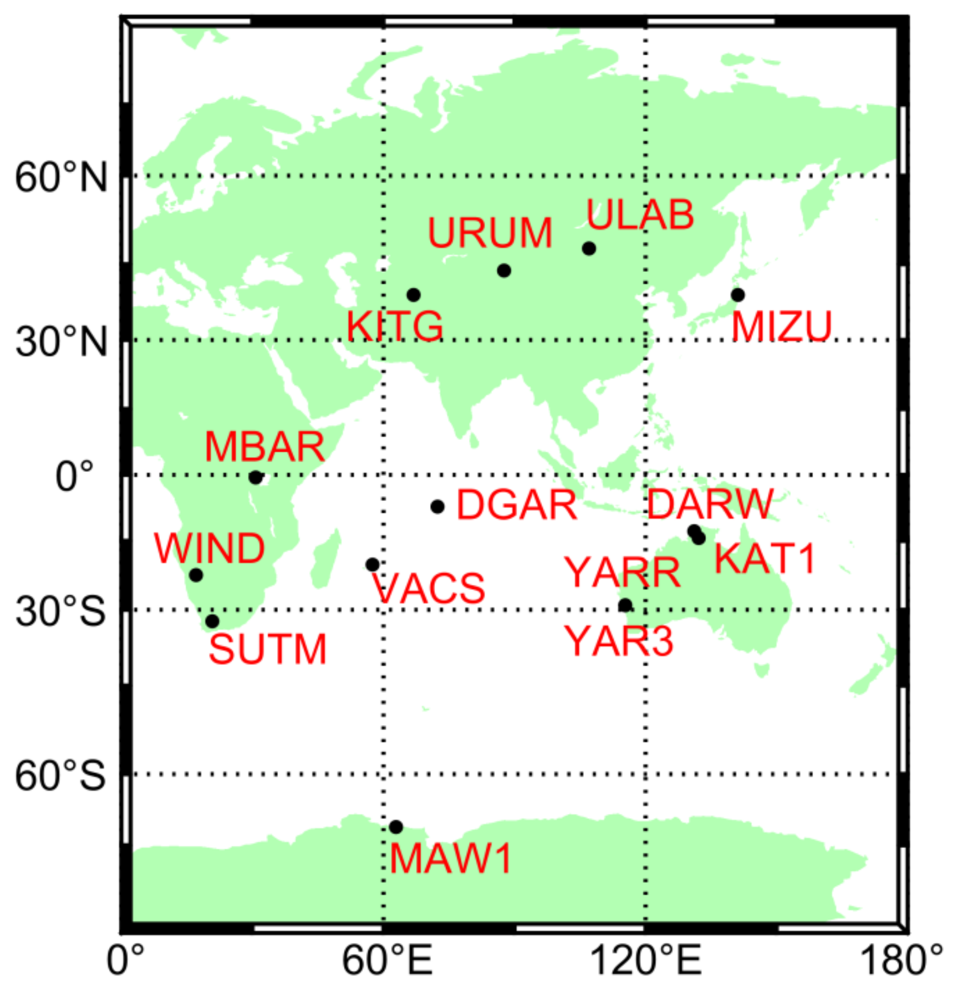
The IRNSS constellation has eight in-orbit satellites at present, and can offer users preliminary positioning, navigation, and timing services over the service regions. This contribution analyzes the current performance of IRNSS-only single-frequency SPP and short-baseline RTK positioning based on the datasets from 14 MGEX stations located in the IRNSS service areas on seven consecutive days. For completeness, the availability of IRNSS constellation (including the visible satellite number, service rate, and PDOP value) is also studied. For comparative analysis, the results of GPS single-system and GPS/IRNSS dual-system combination cases are also provided. In addition, the inter-system bias (ISB) between IRNSS and GPS in the dual-system combined SPP, which was rarely covered by the existing studies, is rigorously analyzed. The paper starts with a description of the constellation and signal of IRNSS. Next, the mathematical model of SPP and RTK is presented. Subsequently, the employed datasets are detailed. Then, the derived results are analyzed and discussed. Finally, the main conclusions are summarized.

2. Constellation and Signal of IRNSS

The IRNSS-1I satellite was successfully launched in April 2018. Currently, the IRNSS constellation has eight in-orbit satellites: three GEO satellites and five IGSO satellites (see Table 1). Figure 1 displays the ground tracks of eight IRNSS satellites on 13 July 2019. The three satellites IRNSS-1C, IRNSS-1F, and IRNSS-1G are positioned at 83° E, 32.5° E, and 129.5° E over the equator, respectively, and their ground tracks all vary within 5° in latitude as the orbit inclination angle is not strictly zero. The repetition period of both GEO and IGSO satellites is 23 h and 56 min. The orbit inclination of the IGSO satellites is 29° (fluctuated by 2°). Regarding the longitude, the IRNSS-1B and IRNSS-1I satellites are in the orbit of 55° E, and the IRNSS-1A, IRNSS-1D, and IRNSS-1E satellites are in the orbit of 111.75° E. The approximate latitude range of ground tracks for the five IGSO satellites is 30° S–30° N.
IRNSS can broadcast signals on two frequencies, namely L5 and S, based on code division multiple access (CDMA) technology (detailed in Table 2). The suitable frequencies for navigation of near 1575 MHz have almost completely been occupied by GPS, GLONASS, Galileo, BDS, and QZSS. Thus, the L1 frequency is not selected for IRNSS. For ease of interoperability of IRNSS with other satellite systems, the L5 signal with a center frequency of 1176.450 MHz is selected as the first signal for IRNSS. IRNSS also chooses an S signal with a center frequency of 2492.028 MHz as its second signal. Compared with the L5 signal, the S signal is less affected by the ionospheric delay due to its larger frequency. IRNSS uses differently modulated L5 and S signals, with a BPSK (1) modulation for SPS users and a BOC (5, 2) modulation for RS users.

3. Methods

In this section, the mathematical model for the GPS/IRNSS integrated position determination is developed, while the corresponding model for the IRNSS-only and GPS-only data processing can be easily derived with the developed mathematical model. The positioning model can be divided into absolute and relative positioning based on different data processing strategies. The absolute positioning includes the SPP and the precise point positioning (PPP). This contribution only analyzes the positioning results of SPP and short-baseline RTK, and does not cover the PPP due to the absence of IRNSS precise ephemeris. Only the pseudorange measurements on the L5 band are used for SPP processing as the receivers at MGEX stations that support IRNSS satellites only receive the L5 signal [15]. The code observations from the IRNSS and GPS satellites can be expressed as follows:
P G = ρ G + t r G t s G + I o n G + T G + ε G P I = ρ I + t r I t s I + I o n I + T I + ε I
where G and I denote satellites of GPS and IRNSS, respectively, P is the measured pseudorange, ρ = X s X r 2 + Y s Y r 2 + Z s Z r 2 is the geometric distance, where ( X s , Y s , Z s ) denotes the satellite coordinates in three dimensions, which can be calculated by the broadcast ephemeris, and ( X r , Y r , Z r ) denotes the receiver coordinates in three dimensions, t r denotes the receiver clock offset (in meters) that absorbs the receiver code hardware delay, t s denotes the satellite clock offset (in meters) after applying the time group delay (TGD) corrections, I o n denotes the ionospheric delay, T denotes the tropospheric delay, and ε denotes the code measurement noises including the multipath errors. The ionospheric delay and tropospheric delay are corrected using the GPS Klobuchar model [16] (can also use the Galileo Nequik-G [17] or the BDS-3 BDGIM [18]) and the Saastamoinen model in this paper, respectively.
When using different observations to estimate the satellite clock offset, the obtained satellite clock estimates are not consistent with each other as the frequency-related satellite code hardware delay is absorbed. Therefore, a bias correction is necessary when the code observations used for SPP processing are different from those adopted by satellite clock estimation. The TGD parameter provided in the broadcast ephemeris (generated with dual-frequency observations) can be employed to derive the consistent satellite clock offset for the single-frequency SPP users. The satellite clock offset with TGD corrections can be formulated as follows:
t s G = t S V G γ G T G D G t s I = t S V I γ I T G D I
with γ G = ( f 1 / f L 5 ) 2 and γ I = ( f S / f L 5 ) 2 where t S V denotes the satellite clock offset calculated by the broadcast ephemeris, f 1 , f L 5 and f S denote the carrier frequency on the L1, L5 and S bands, respectively, and T G D denotes the correction of the TGD.
The IRNSS System Time (IRNSST) started at 00:00:00 on 22 August 1999, which corresponds to the Coordinated Universal Time (UTC) 23:59:47 on 21 August 1999 (same time as the first GPS week with a roll-over). IRNSST is a continuous time without leap seconds, and it is determined by the IRNSS System Precise Timing Facility (IRNPT) with an ensemble of Caesium and Hydrogen maser standard atomic clocks, which is steered to UTC. The time offset between IRNSST and GPS time could be several nanoseconds [19], and thus cannot be ignored in the IRNSS/GPS integrated data processing. IRNSS takes WGS-84 coordinate system as its space reference. Therefore, the transformation of satellite coordinates is unnecessary in the integrated data processing with IRNSS and GPS. Although the center frequency of L5 band is identical for IRNSS and GPS, there may still be difference in the receiver code hardware delay between the two satellite systems. This contribution uses GPS as the reference system, and introduces the ISB parameter into the code observation equation of IRNSS to account for the distinct time scale and hardware delay [20].
The linearized observation model for the GPS/IRNSS combined SPP can be expressed as follows:
O U + v = H Δ X
where O U denotes the vector of observed-minus-computed (OMC) code observables, v denotes the observation residual error vector, H denotes the design matrix, and Δ X denotes the unknown parameter residual error vector between the true value and the approximate value. H and Δ X can be formulated as follows:
O U = p G 1 , , p G n , p I 1 , , p I m T
H = X 0 X s G 1 ρ 0 G 1 Y 0 Y s G 1 ρ 0 G 1 Z 0 Z s G 1 ρ 0 G 1 1 0 X 0 X s G n ρ 0 G n Y 0 Y s G n ρ 0 G n Z 0 Z s G n ρ 0 G n 1 0 X 0 X s I 1 ρ 0 I 1 Y 0 Y s I 1 ρ 0 I 1 Z 0 Z s I 1 ρ 0 I 1 1 1 X 0 X s I m ρ 0 I m Y 0 Y s I m ρ 0 I m Z 0 Z s I m ρ 0 I m 1 1
Δ X = Δ x Δ y Δ z Δ t r G Δ t I S B T
where p denotes the OMC code observables, ( X 0 , Y 0 , Z 0 ) denotes the approximate 3D coordinates of the receiver, ρ 0 is the geometric distance between the receiver approximate position and the satellite position, n and m are the satellite numbers of GPS and IRNSS, respectively, ( Δ x , Δ y , Δ z ) denotes the receiver coordinate residual errors (i.e., corrections) with respect to the approximate position, Δ t r G denotes the residual error of the GPS receiver clock offset, and Δ t I S B is the residual error of the ISB parameter t I S B (with t I S B = t r I t r G ). The least squares adjustment is used for the parameter estimation in SPP processing.
In addition to the code observations, the RTK positioning includes the carrier phase observations, which can be expressed as follows:
Φ G = ρ G + t r G t s G I o n G + T G + d r G + d s G + λ G N G + ξ G Φ I = ρ I + t r I t s I I o n I + T I + d r I + d s I + λ I N I + ξ I
where Φ is the phase observation in meters, λ is the wavelength, N is the integer phase ambiguity in cycles, ξ is the phase measurement noises including multipath errors, d r is the grouped receiver phase and code hardware delay, and d s is the grouped satellite phase and code hardware delay.
Regarding the relative positioning, the difference between different observations can form a combined observable, so as to weaken the influence of various errors and biases. The single-difference between stations can eliminate the satellite clock errors and satellite hardware delay, and weaken the ionospheric delay, tropospheric delay, and satellite orbit errors. The inter-satellite single-difference can remove the receiver clock errors and receiver hardware delay. The double-difference carrier phase measurements can be expressed as follows:
Δ Φ i , j G , A , B = Δ ρ i , j G , A , B Δ I o n i , j G , A , B + Δ T i , j G , A , B + λ G Δ N i , j G , A , B + Δ ξ i , j G , A , B Δ Φ i , j I , A , B = Δ ρ i , j I , A , B Δ I o n i , j I , A , B + Δ T i , j I , A , B + λ I Δ N i , j I , A , B + Δ ξ i , j I , A , B
where Δ denotes the double-difference operation, A and B denote two satellites from GPS or IRNSS, and i and j denote two stations. The effects of residual errors of ionospheric delay and tropospheric delay can be ignored during the processing of short-baseline RTK, and the double-difference carrier phase observation equation can be simplified as follows:
Δ Φ i , j G , A , B = Δ ρ i , j G , A , B + λ G Δ N i , j G , A , B + Δ ξ i , j G , A , B Δ Φ i , j I , A , B = Δ ρ i , j I , A , B + λ I Δ N i , j I , A , B + Δ ξ i , j I , A , B
The linearized observation model of the GPS/IRNSS combined short-baseline RTK can be described as follows:
O D + v D = H D X D
O D = O D G , O D I T O D G = Δ p i , j G 1 , G b , Δ ϕ i , j G 1 , G b , , Δ p i , j G n 1 , G b , Δ ϕ i , j G n 1 , G b O D I = Δ p i , j I 1 , I b , Δ ϕ i , j I 1 , I b , , Δ p i , j I m 1 , I b , Δ ϕ i , j I m 1 , I b
H D = α G 1 β G 1 χ G 1 0 0 0 0 α G 1 β G 1 χ G 1 λ G 0 0 0 α G n 1 β G n 1 χ G n 1 0 0 0 0 α G n 1 β G n 1 χ G n 1 0 λ G 0 0 α I 1 β I 1 χ I 1 0 0 0 0 α I 1 β I 1 χ I 1 0 0 λ I 0 α I m 1 β I m 1 χ I m 1 0 0 0 0 α I m 1 β I m 1 χ I m 1 0 0 0 λ I
α G k = X 0 X s G k ρ 0 G k X 0 X s G b ρ 0 G b β G k = Y 0 Y s G k ρ 0 G k Y 0 Y s G b ρ 0 G b χ G k = Z 0 Z s G k ρ 0 G k Z 0 Z s G b ρ 0 G b α I q = X 0 X s I q ρ 0 I q X 0 X s I b ρ 0 I b β I q = Y 0 Y s I q ρ 0 I q Y 0 Y s I b ρ 0 I b χ I q = Z 0 Z s I q ρ 0 I q Z 0 Z s I b ρ 0 I b
X D = X r , Y r , Z r , Δ N G 1 , , Δ N G n 1 , Δ N I 1 , , Δ N I m 1 T
where O D is the vector of dual-difference OMC code and carrier phase observables, v D denotes the observation residual error vector in the short-baseline RTK positioning, H D denotes the design matrix in the short-baseline RTK positioning, X D is the vector of estimates in the short-baseline RTK positioning, Δ p is the double-difference OMC code observables, Δ ϕ is the double-difference OMC carrier phase observables, n and m denote the satellite number of GPS and IRNSS, respectively, G b and I b denote the reference satellite of GPS and IRNSS, respectively, G k ( k = 1 , 2 , , n 1 ) and I q ( q = 1 , 2 , , m 1 ) denote a satellite of GPS and IRNSS, respectively, and α , β and χ denote the linearization coefficients related to receiver coordinates in the design matrix H D . The meanings of other parameters are the same as the aforementioned ones, and thus we do not repeat them again. According to Equation (14), the parameters to be estimated in the short-baseline RTK positioning comprise the 3D receiver coordinates and the double-difference phase ambiguities of GPS and IRNSS. The Kalman filter is used for the parameter estimation in the short-baseline RTK processing. The receiver coordinates are estimated as white noise process, and the double-difference phase ambiguity parameters are estimated as integer constants. The least-squares ambiguity de-correlation adjustment (LAMBDA) method [21] is used for the ambiguity resolution (AR).
In addition to the rigorous functional model, a suitable stochastic model can also improve the positioning performance. Usually, the observations can be influenced by the ionosphere, troposphere, and multipath effect during the propagation of satellite signals. All these influencing factors are related to the satellite elevation angles. Therefore, in this study, an elevation-dependent model is used to determine the weights of observations. Assuming that there is no correlation between the measurements of different types, from different satellites, or at different stations, the variances of undifferenced observations can be calculated as follows:
σ 2 ( e l ) = σ 0 2 sin e l 2
where σ 0 is the standard deviation (STD) of observations at zenith, e l denotes the satellite elevation angle, and σ ( e l ) is the STD of observations at the elevation angle e l . In this contribution, σ 0 is set to 3 dm and 1.9 mm (one percent of chip length or wavelength) for the code and carrier phase observations from GPS satellites, respectively. It is considered that the accuracy of broadcast ephemeris and the quality of satellite signals of IRNSS are inferior to those of GPS, and thus the adopted σ 0 of the code and carrier phase observations from IRNSS satellites is empirically 1.5 times and 2.0 times as large as that of GPS code and phase, respectively (i.e., 4.5 dm and 3.8 mm).

4. Data Sets

The observations from 14 MGEX stations in the service areas of IRNSS on seven consecutive days from 7–13 July 2019, are used for analysis, and the distribution of the employed MGEX stations is shown in Figure 2. The details of each station are provided in Table 3. All stations equipped with geodetic receivers can support the IRNSS L5 signal, and are able to simultaneously track at least four IRNSS satellites for more than 12 h in a single day. The sampling rate of observations is 30 s, and the cut-off elevation is set to 10°. Single-frequency (GPS L1 and IRNSS L5) SPP and RTK are carried out to investigate the positioning performance.

5. Results and Analysis

5.1. Availability of Satellite Constellation

This section focuses on the availability assessment of IRNSS constellation in terms of the visible satellite numbers, service rates, and PDOP values. For comparative analysis, the results of GPS-only and GPS/IRNSS cases are also provided. The precise ephemeris products of IRNSS are absent at present, and thus the assessment is based on the coordinates of IRNSS and GPS satellites calculated by the broadcast ephemeris. According to the strategies described in Yang et al. [22], the whole world can be divided into 72 × 72 grids with a spatial resolution of 2.5° (latitude) by 5° (longitude), and the center of each grid is taken as the position for the virtual stations. The sampling interval is 30 s, and the elevation cut-off angle is set to 10°. The availability of satellite constellation is evaluated by analyzing the relative geometry of virtual receivers and employed satellites. The assessment is based on the single-day data on 12 July 2019, with the view that the orbit repetition period is one day for both GPS and IRNSS satellites.
The global distribution of the average number of visible satellites over a day for the IRNSS-only case is displayed in Figure 3. The IRNSS satellite signals cannot be received in a large elliptic region (marked in white in Figure 3), which is centered at 97.5° W on the equator, and extends from 40° W to 160° W, and from 77.5° S to 77.5° N. In the areas with 80°E on the equator as the center, the west and east sides extending to 60° E and 100° E, and the north and south sides extending to 57.5° N and 57.5° S, users can observe 6–8 IRNSS satellites. These areas cover the primary service areas of IRNSS. Usually, there are also at least four visible IRNSS satellites in the secondary service areas as a result of the configuration of the IRNSS constellation. The average number of visible satellites for the GPS-only and GPS/IRNSS cases is shown in Figure 4. For the GPS-only case, the average value of visible GPS satellites over the middle and low latitude regions (15° N–60° N and 15° S–60° S) is 8.8, which is less than that over the other areas with a statistic of 9.9. The GPS/IRNSS integration can significantly increase the number of visible satellites in the IRNSS primary service areas, which reaches 15.0–17.7, while the corresponding satellite number in the IRNSS primary and secondary service areas ranges from 12.3 to 17.7.
Usually, the position determination is considered to be feasible when at least four satellites are visible, and the PDOP value is less than 25. The service rate is the percentage of the time span, during which the positioning service is available, over the total analysis period (a day). The global distribution of the service rate of the IRNSS-only case is shown in Figure 5. The areas where the positioning service is always unavailable are marked in white in Figure 5. The service rate of IRNSS-only case reaches nearly 100.0% in the primary service areas. The average service rate of IRNSS-only cases over the secondary service areas is 88.4%. In addition, the service rate of IRNSS-only case decreases with the increasing distance from the primary service areas. The service rate of GPS-only and GPS/IRNSS cases is presented in Figure 6, which shows that the service rate for the two cases reaches 100.0% worldwide.
The distribution of the average PDOP value over the time span when the positioning service of the IRNSS-only case is available is displayed in Figure 7. The areas where the position determination is always unavailable are also marked in white in Figure 7. The PDOP value in primary service areas is between 3.3 and 6.2 under the IRNSS-only case, basically less than 15 in secondary service areas, and above 20 in some marginal regions beyond the IRNSS service areas. The distribution of the PDOP values of the GPS-only case and the GPS/IRNSS case is shown in Figure 8. The average statistic of PDOP value for the GPS-only case over all the latitude and longitude regions is 2.0, and the minimum PDOP value of 1.7 on the equator is achieved. The PDOP value of the GPS-only case increases first and then decreases with the increasing latitudes in middle and low latitude regions, after which it gradually increases toward the poles until reaching the peak value of 2.3. The PDOP value of the GPS/IRNSS case in the primary and secondary service areas of IRNSS varies from 1.3 to 1.7 with an average statistic of 1.5. Thus, the GPS/IRNSS combination can improve the satellite sky distribution for the service areas of IRNSS.

5.2. Positioning Accuracy of SPP and Characteristics of ISB Estimates

In this section, the positioning performance of the IRNSS-only SPP is assessed based on the 14 MGEX stations (see Figure 2). For comparative analysis, the results of the other two cases (GPS-only and GPS/IRNSS) are also provided. The epoch-wise root mean square (RMS) statistics of positioning errors at the same epochs for all the 24-h datasets from the employed seven days and 14 stations are calculated. Figure 9 displays the epoch-wise RMS statistics of positioning errors in the east, north and up directions under two single-system cases, namely IRNSS-only and GPS-only SPP. The epoch-wise positioning accuracy of IRNSS-only SPP is better than 10.0, 11.3 and 13.6 m in the three directions, respectively, but with large fluctuations. The overall positioning accuracy (i.e., RMS statistics of positioning errors over all the available epochs from all the used days and stations) of IRNSS-only SPP is 6.031, 6.015 and 9.668 m in the three directions, respectively. In contrast, the epoch-wise positioning accuracy of GPS-only SPP is better than 0.8, 1.3 and 3.2 m in the three directions, respectively, and the overall positioning accuracy is 0.519, 0.815 and 2.293 m in the three directions, respectively. The analysis shows that under the current constellation conditions, the positioning accuracy of IRNSS-only SPP is far worse than that of GPS-only SPP, even in the service areas of IRNSS. The epoch-wise RMS statistics of positioning errors in the 3D direction for the three cases, namely IRNSS-only, GPS-only, and GPS/IRNSS SPP, are shown in Figure 10. The epoch-wise 3D positioning accuracy is better than 18.3, 3.3, and 3.0 m for the three cases, respectively. The overall 3D positioning accuracy under IRNSS-only, GPS-only, and GPS/IRNSS cases is 12.885, 2.489, and 2.237 m, respectively. Compared with the IRNSS-only SPP, the 3D positioning accuracy of the GPS/IRNSS integrated solutions is improved by 82.6%. In comparison with the GPS-only SPP, the 3D positioning accuracy of the GPS/IRNSS integrated solutions is improved by 10.1%. For further analysis, Figure 11 provides the station-dependent RMS statistics of 3D positioning errors for IRNSS-only SPP. It is indicated that the positioning accuracy is consistent with PDOP performance (see Figure 7).
The code observation residuals that contain measurement noises and other unmodeled errors can be used as an important index to evaluate the SPP mathematical model. The code observation residuals derived from the GPS/IRNSS SPP based on the datasets collected at 14 MGEX stations spanning seven consecutive days from 7–13 July 2019, are used for analysis. Figure 12 displays the distribution of code residuals for the GPS and IRNSS satellites, as well as the corresponding residual statistics (including the RMS value and average value). The code residuals of GPS are more concentrated than those of IRNSS. The code residuals of GPS are basically within ±3 m, and the corresponding varying range of IRNSS is relatively larger (within ±4.5 m). The RMS value of the code residuals of GPS is 0.808 m, and is increased to 1.203 m for IRNSS. Regarding the average value of code observation residuals, it is −0.012 m for GPS, and is increased to 0.050 m for IRNSS. Under the GPS/IRNSS case, the code residuals of GPS and IRNSS satellites approximately obey the normal distribution. Based on the analysis and evaluation, it is indicated that the adopted SPP mathematical model is rigorous, and all types of biases and errors have been properly handled.
Figure 13 shows the time series of epoch-wise ISB estimates between IRNSS and GPS at 14 MGEX stations on 7–13 July 2019, namely day of year (DOY) 188 to 194 of 2019. The ISB estimates are derived from the GPS/IRNSS combined SPP solutions. Based on Equations (3)–(6), the ISB parameter can be solved even when only one IRNSS satellite and at least four GPS satellites (note that there are generally about nine GPS satellites at each epoch in the datasets) are available. However, according to the least-squares adjustment, the code observation residuals of this IRNSS satellite will equal to zero, which results in unreliable ISB estimates [23]. Therefore, only the epoch-wise ISB estimates with at least two IRNSS satellites are used for analysis here. As a result of the unstable tracking for IRNSS satellites by some stations, such as the URUM and VACS stations, the ISB results are absent during partial time spans at these stations. Some common mode components of ISB throughout the 14 stations can be observed, which is caused by the time-offset between IRNSS and GPS systems. In addition, the epoch-wise ISB series have obvious periodic characteristics, and the period is consistent with the orbit repetition period of IRNSS and GPS satellites, namely one day. This can be well-explained by satellite distribution, namely the ISB-specific DOPs with periodic characteristics (see Figure 14). In addition, the single-epoch ISB estimates vary within 30 ns for the seven-day datasets, indicating that the ISB cannot be ignored when performing the data processing of GPS/IRNSS combined SPP.

5.3. Performance of Short-Baseline RTK Positioning

Due to the limited number of available IRNSS satellites and the unstable tracking of IRNSS satellites by the MGEX stations, it is difficult to perform the IRNSS-only long-baseline precise relative positioning. In this section, the performance of the IRNSS single-system short-baseline RTK positioning is assessed based on the datasets from the two stations YARR and YAR3 spanning seven consecutive days from 7–13 July 2019. The length of the short baseline is approximately 20 m. For comparative analysis, the results of the GPS-only and GPS/IRNSS cases are also provided. In the short-baseline RTK, only GPS L1 and IRNSS L5 signals are used. Reference baseline values are obtained in static relative positioning based on the seven-day datasets. Figure 15 illustrates the epoch-wise position errors of the ambiguity-fixed solutions for IRNSS-only, GPS-only, and GPS/IRNSS short-baseline RTK on 7 July 2019. The epoch-wise position errors of IRNSS-only cases are less than 5 cm in the horizontal direction and 10 cm in the vertical direction, while those of both GPS-only and GPS/IRNSS cases are smaller than 1 cm in the horizontal direction and 3 cm in the vertical direction. The RTK solutions of GPS-only and GPS/IRNSS cases are comparable in the three directions.
We further analyze the service rate, ASR, mean positioning bias, and STD value of the positioning error for the single-day short-baseline RTK results under the three system combination cases. When the ratio-test value is larger than three, the ambiguity is considered to be successfully fixed. The service rate refers to the percentage of the number of epochs, at which the position solutions (including both ambiguity-float and ambiguity-fixed solutions) can be achieved over the total epochs. The ASR is taken as the percentage of the number of epochs with successfully fixed ambiguities over that with available ambiguity-float or ambiguity-fixed position solutions. Table 4 shows the 7-day average results of these statistical values. The service rate of the IRNSS-only case is 71.5%, and that of the other two cases reaches 100.0%. In addition, the ASR of the IRNSS-only case is only 64.0%, and that of the other two cases reaches nearly 100.0% (specifically 99.5% for GPS and 99.9% for GPS/IRNSS). Regarding the mean positioning biases, they are at the centimeter level for the IRNSS-only case, which are 5.4, −21.1, and −0.2 mm in the east, north, and up directions, respectively. The GPS-only case has significantly smaller mean positioning biases than the IRNSS-only case, which are reduced to −0.3, −0.1, and −3.4 mm in the three directions, respectively. The introduction of IRNSS observations slightly pollutes the accurate GPS-only results perhaps due to the severe multipath-like interferences as shown in the IRNSS-derived coordinates (see Figure 15). Regarding the STD value of positioning errors, it is 7.8, 19.2, and 29.0 mm for the IRNSS-only case in the three directions, respectively, whereas that of the GPS-only case is much better, which is reduced by 61.5%, 85.4%, and 68.3% to 3.0, 2.8, and 9.2 mm in the three directions, respectively. The GPS/IRNSS integration slightly increases the STD error in the north and up directions compared with the GPS-only case, while the corresponding reduction in STD error can be 65.4%, 80.7%, and 64.8% in the three directions compared with the IRNSS-only case, respectively. Compared to the single-frequency short-baseline RTK positioning performance of BDS-3 that also covers Asian areas (e.g., [24], with RMS positioning errors of 3–8 mm in the horizontal directions and 9–19 mm in the vertical direction, and ASR of higher than 91%), that of IRNSS is obviously worse (with RMS positioning errors of 9.5/28.5/29.0 mm in the three directions, and ASR of 64%).
Figure 16 displays the distribution of carrier phase observation residuals of ambiguity-fixed solutions derived from GPS/IRNSS integrated short-baseline RTK for GPS and IRNSS satellites. The residual analysis here is based on the 7-day datasets at the stations YARR and YAR3. The GPS phase observation residuals are mainly concentrated within 1.5 cm, while those of IRNSS satellites are mainly within 2.0 cm. The average value and the RMS value of the GPS phase observation residuals are −3 and 5 mm, respectively, while the two statistical values of the IRNSS phase observation residuals are 5 and 12 mm, respectively. GPS satellites exhibit better performance than IRNSS satellites in terms of the two residual statistics. The phase observation residuals of both GPS and IRNSS satellites are approximately normally distributed, which demonstrates that the employed short-baseline RTK mathematical model is also rigorous, and the various biases and errors have also been properly handled.

6. Discussion

Although there are only eight available IRNSS satellites at present, the positioning performance of the IRNSS single-system SPP (with meter-level accuracy) and short-baseline RTK positioning (with a centimeter-level accuracy) is still acceptable in its service areas. As satellite-based positioning technologies, both SPP and RTK depend on the available satellites. In the future, with the continuous improvement of IRNSS constellation and the increased number of ground tracking stations, a better performance of IRNSS single-system navigation and positioning can be expected.
Compared with GPS single-system results, the accuracy improvement coming with GPS/IRNSS integration is not obvious. This may be due to the satellite geometry being strong, and the positioning accuracy being satisfactory, even for GPS-only cases under an open sky environment. Despite this, the reliability of GPS/IRNSS integrated position solutions can be enhanced. When the users are in environments with limited satellite visibility such as in urban canyons, mountainous areas and open-pit mines, etc., the benefits from GPS/IRNSS integration for position determination are expected to be more significant.

7. Conclusions

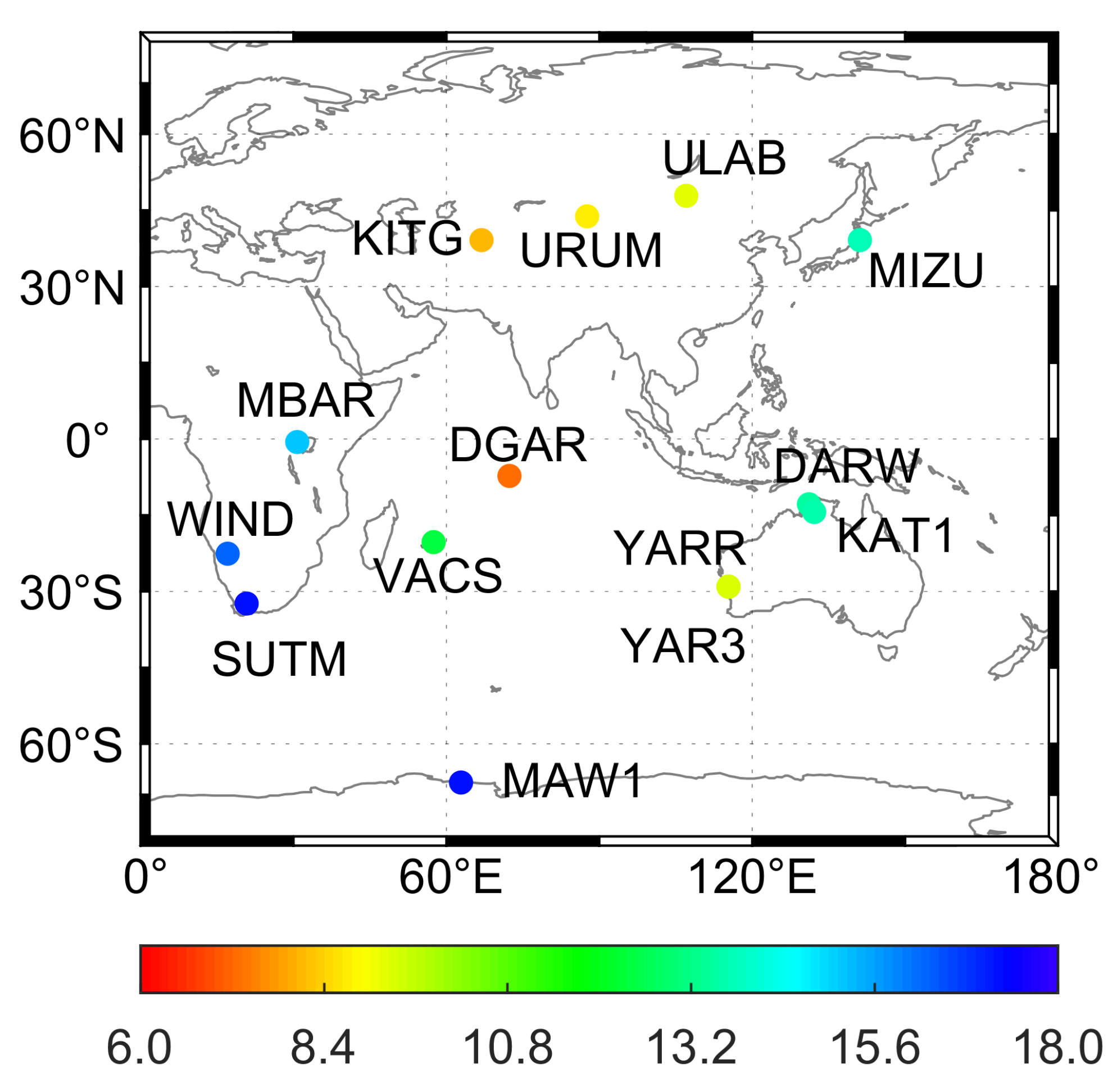
Currently, the IRNSS has eight in-orbit satellites, and has the preliminary capability to provide the standalone navigation and positioning services in the service areas. This contribution investigates the current status of IRNSS single-system data processing, including the availability (i.e., the number of visible satellites, the service rate, and the PDOP value), the single-frequency SPP performance, and the single-frequency short-baseline RTK positioning performance. For comparative analysis, the results of the GPS single-system case and the GPS/IRNSS dual-system combination case are also provided. The datasets from 14 MGEX stations spanning a week from 7–13 July 2019 are employed.
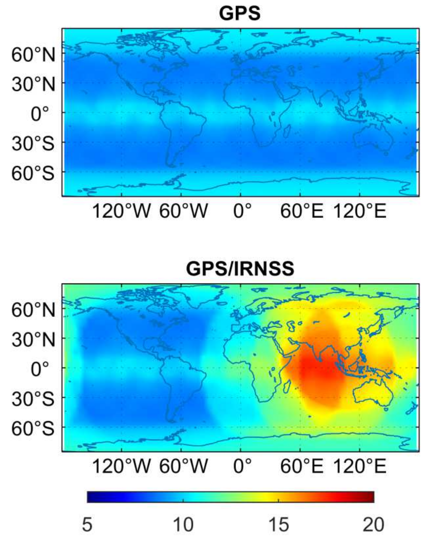
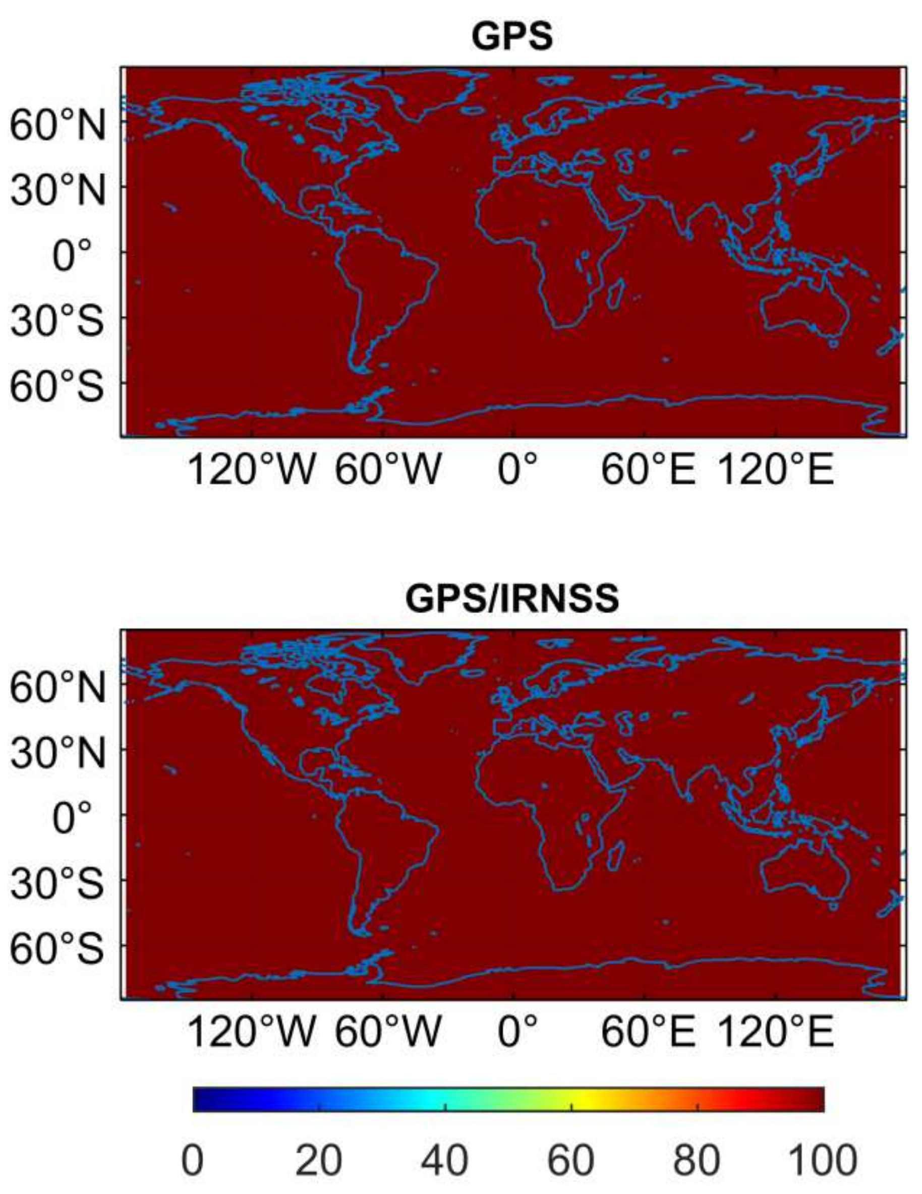
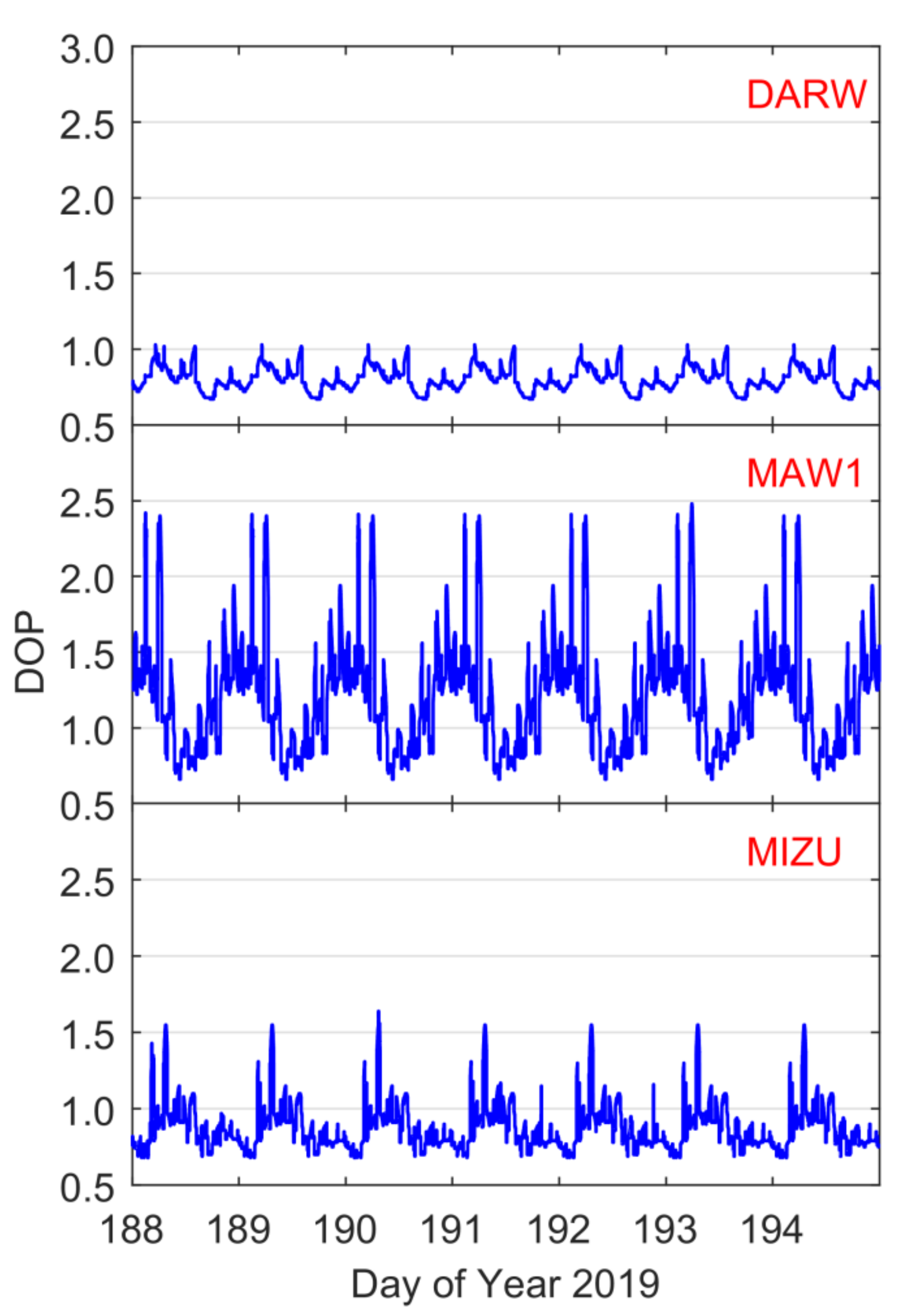
Regarding the theoretical availability of IRNSS constellation under a cut-off elevation angle of 10°, there are 6–8 visible IRNSS satellites in its primary service areas, and at least four IRNSS satellites can be tracked in the secondary service areas. The service rate of IRNSS-only cases in the primary service areas is nearly 100.0%, and the corresponding average value over the secondary service areas can still be up to 88.4%. The average PDOP value of IRNSS-only cases fall between 3.3 and 6.2 in the primary service areas, and is usually less than 15 in the secondary service areas. The GPS/IRNSS dual-system combination can significantly increase the number of visible satellites and reduce the PDOP value in the IRNSS service areas.
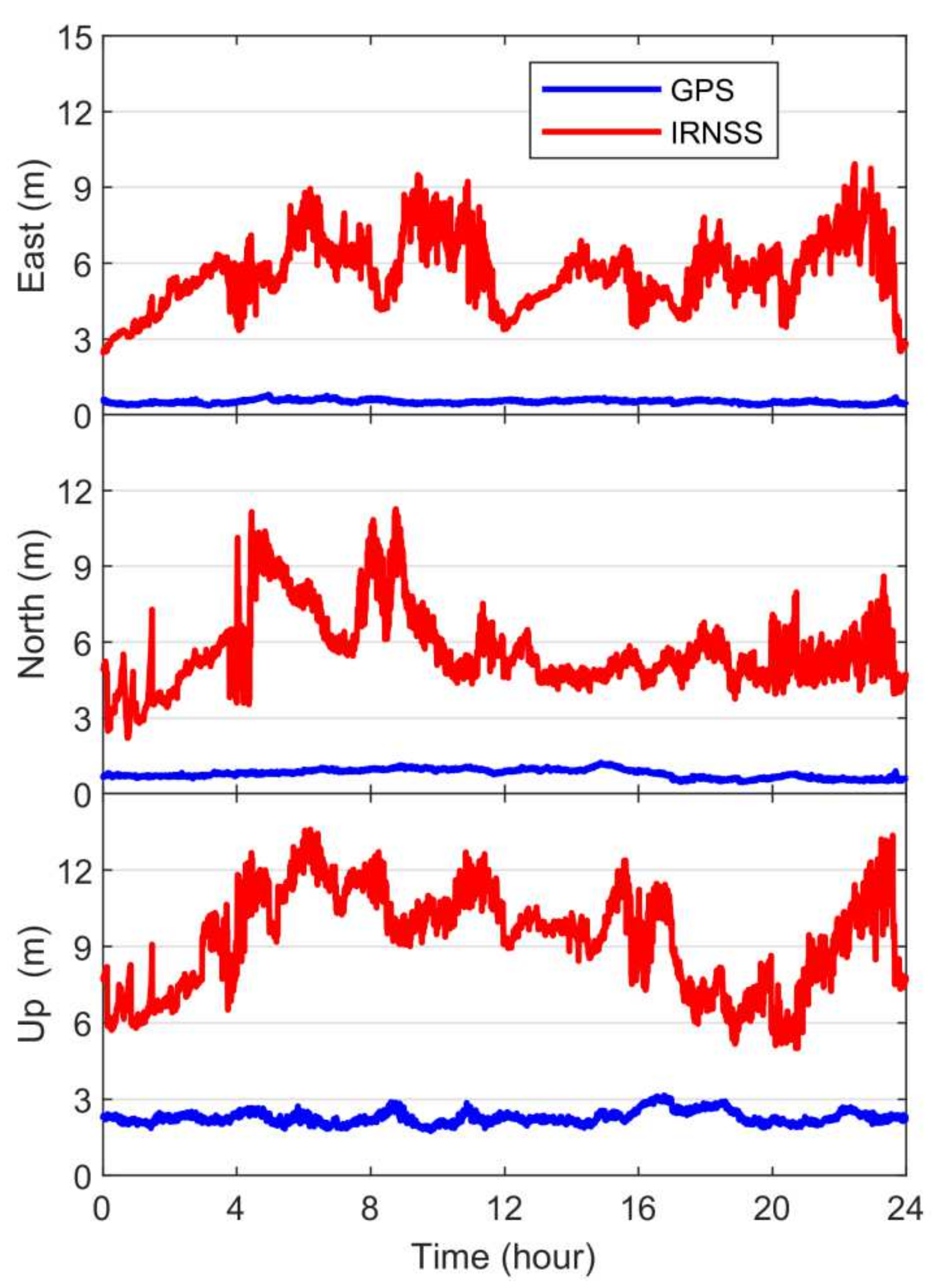
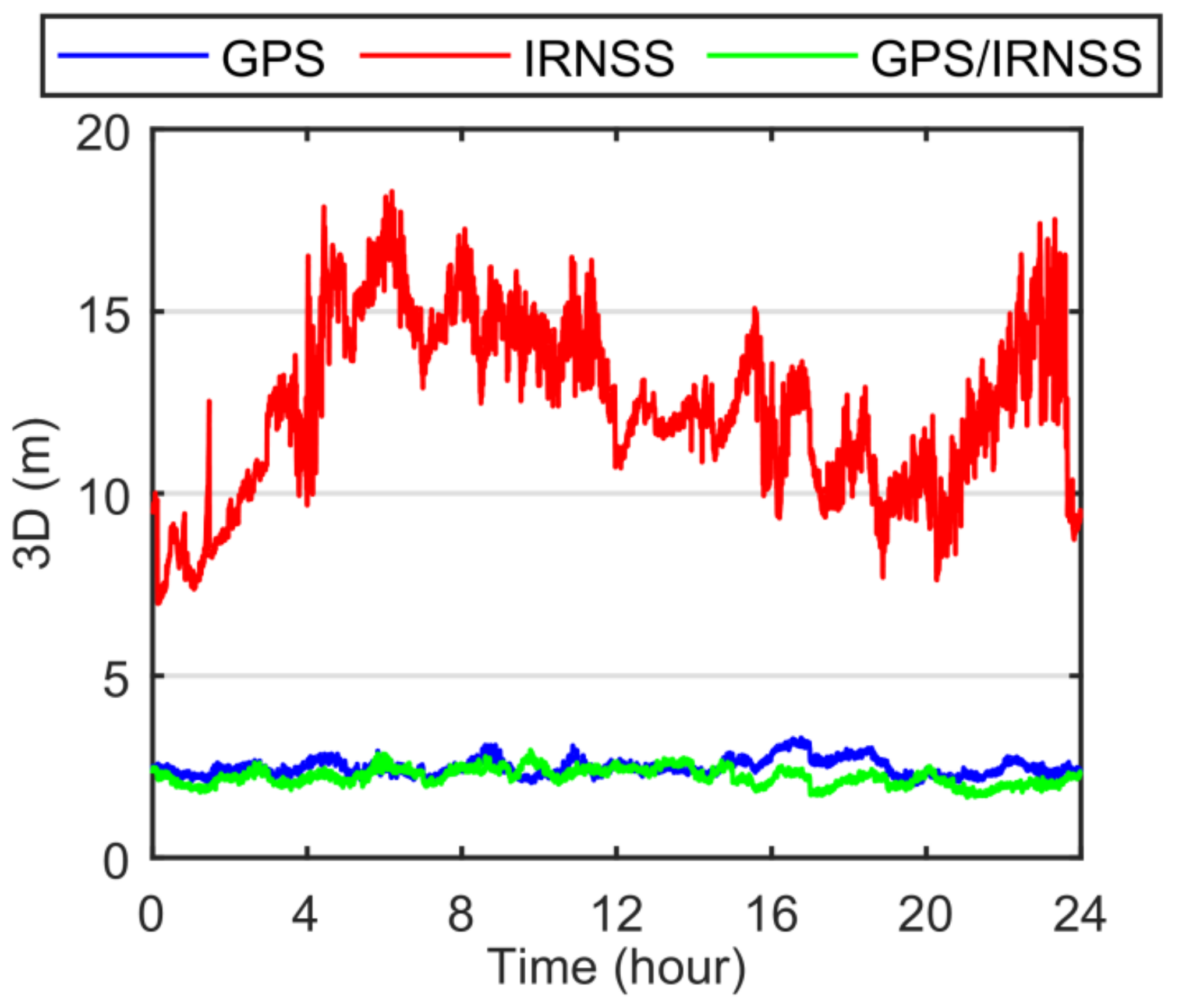
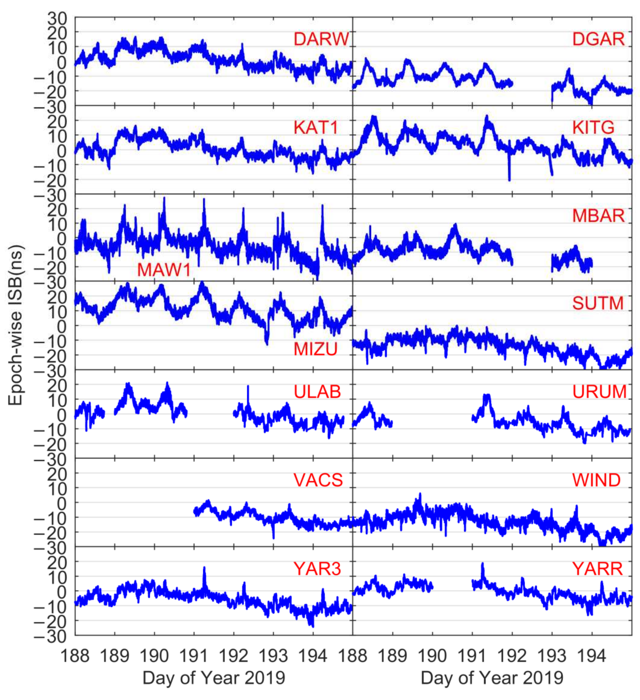
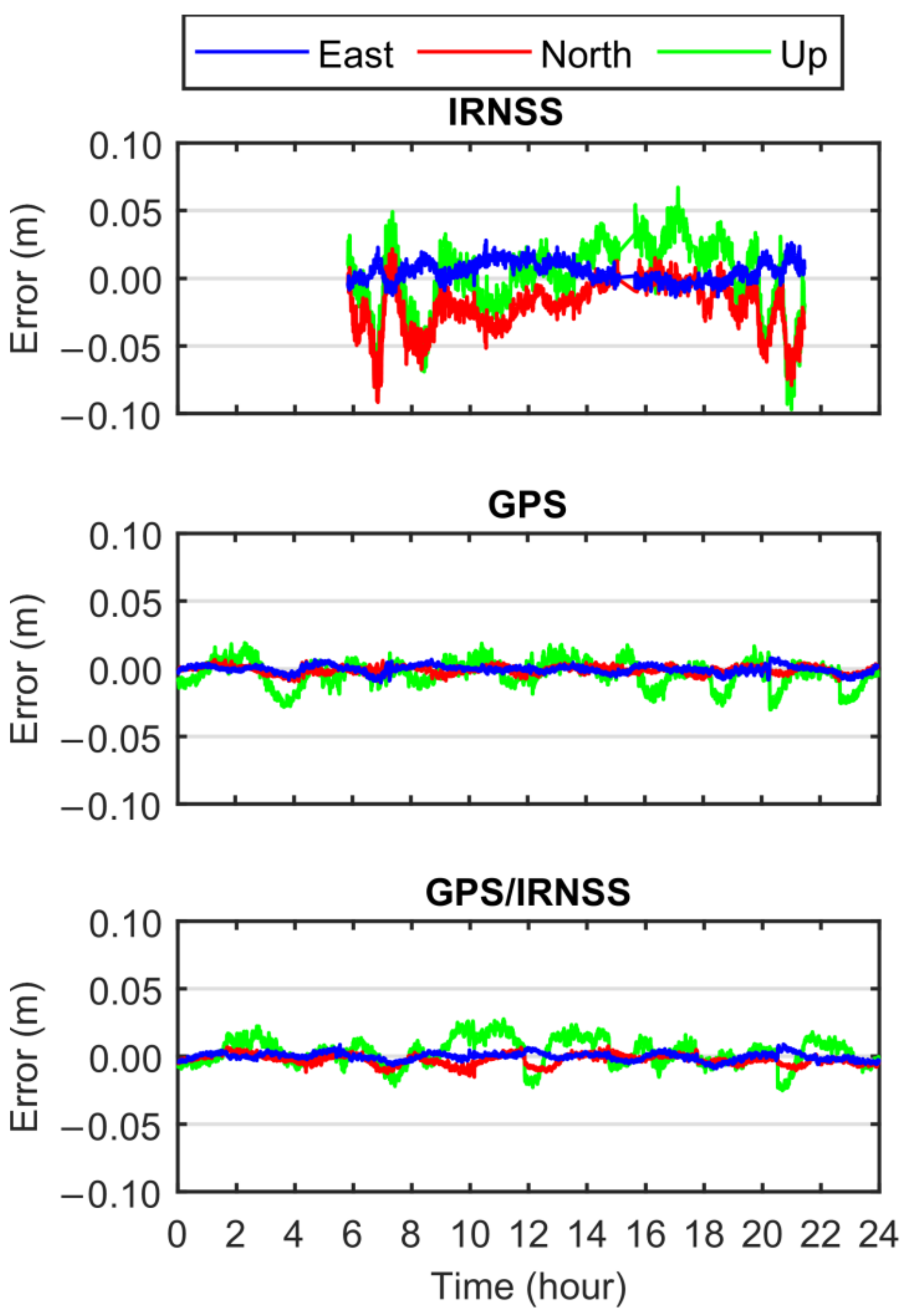
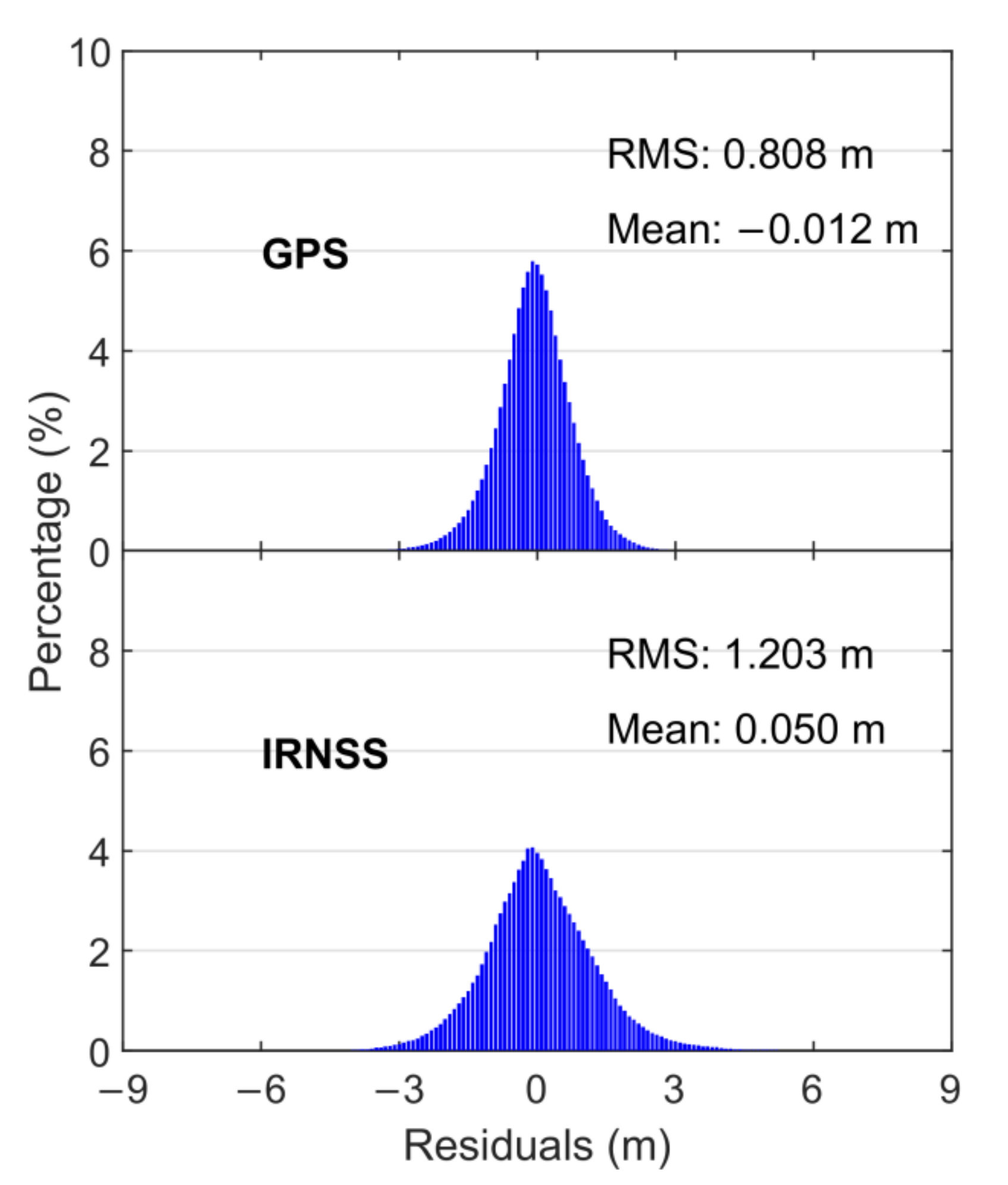
The positioning accuracies of the IRNSS single-system SPP are 6.031, 6.015, and 9.668 m in the east, north, and up directions, respectively, and those of the GPS single-system SPP are 0.519, 0.815, and 2.293 m in the three directions, respectively. The GPS/IRNSS dual-system combined SPP can improve the 3D positioning accuracy by 10.1% and 82.6% over the GPS-only and IRNSS-only cases, respectively. The RMS statistics of code observation residuals derived from the GPS/IRNSS integrated SPP solutions are 1.203 and 0.808 m for the IRNSS and GPS satellites, respectively. The time series of single-epoch ISB estimates between IRNSS and GPS (in the GPS/IRNSS combined SPP solutions) have an obvious periodic characteristic, which coincides with the satellite orbit repetition period (i.e., a day). Moreover, the epoch-wise ISBs vary within 30 ns for the 7-day datasets, which indicates that the ISB between IRNSS and GPS cannot be ignored. The service rate and ASR of the IRNSS single-system short-baseline RTK positioning are 71.5% and 64.0%, respectively, and those of the GPS single-system case are both close to 100.0%. The mean positioning biases of the IRNSS single-system short-baseline RTK positioning are 5.4, −21.1, and −0.2 mm in the three directions, respectively. The accuracy of the GPS-only short-baseline RTK is significantly better than that of the IRNSS-only case, and the corresponding errors decrease to −0.3, −0.1, and −3.4 mm in the three directions, respectively. Compared with the GPS single-system case, the mean positioning biases of the GPS/IRNSS combined short-baseline RTK are comparable and those in the east and up directions are slightly reduced. As to the STD value of the short-baseline RTK positioning errors, the condition is similar to that of the mean positioning biases. The STD statistics of the IRNSS-only solution are 7.8, 19.2, and 29.0 mm in the three directions, respectively, and the corresponding values are reduced by 61.5%, 85.4%, and 68.3%, and 65.4%, 80.7%, and 64.8% for GPS-only and GPS/IRNSS cases, respectively. The RMS values of carrier phase observation residuals derived from GPS/IRNSS combined short-baseline RTK positioning for GPS satellites are 5 mm, and those of IRNSS satellites increase to 12 mm.

Author Contributions

Conceptualization, L.P. and W.Y.; methodology, L.P.; software, L.P. and G.P.; validation, L.P. and G.P.; formal analysis, G.P. and L.P.; investigation, G.P. and L.P.; resources, G.P.; data curation, G.P. and Z.Z.; writing—original draft preparation, G.P. and L.P.; writing—review and editing, Z.Z., W.Y. and L.P.; visualization, G.P. and L.P.; supervision, L.P.; project administration, L.P.; funding acquisition, L.P. All authors have read and agreed to the published version of the manuscript.

Funding

This research was funded by the National Natural Science Foundation of China (Grant No. 41904030), Natural Science Foundation of Hunan Province, China (Grant No. 2020JJ5706), State Key Laboratory of Geo-Information Engineering (Grant No. SKLGIE2019–Z–1–1), and Science and Technology Project of Department of Natural Resources of Hunan Province (Grant No. 2021-24).

Data Availability Statement

Publicly available datasets were analyzed in this study. This data can be found from MGEX.

Acknowledgments

The contribution of data from MGEX is appreciated.

Conflicts of Interest

The authors declare no conflict of interest. The funders had no role in the design of the study; in the collection, analyses, or interpretation of data; in the writing of the manuscript, or in the decision to publish the results.

References

  1. Department of Space, Indian Space Research Organization. List of Navigation Satellites. Available online: https://www.isro.gov.in/spacecraft/list-of-navigation-satellites (accessed on 16 April 2022).
  2. Mukesh, R.; Karthikeyan, V.; Soma, P.; Sindhu, P. Analysis of signal strength, satellite visibility, position accuracy and ionospheric TEC estimation of IRNSS. Astrophys. Space Sci. 2019, 364, 196. [Google Scholar] [CrossRef]
  3. Zaminpardaz, S.; Teunissen, P.J.G.; Nadarajah, N. IRNSS/NavIC and GPS: A single- and dual-system L5 analysis. J. Geod. 2017, 91, 915–931. [Google Scholar] [CrossRef] [Green Version]
  4. Zaminpardaz, S.; Teunissen, P.J.G.; Nadarajah, N. Single-frequency L5 attitude determination from IRNSS/NavIC and GPS: A single- and dual-system analysis. J. Geod. 2017, 91, 1415–1433. [Google Scholar] [CrossRef] [Green Version]
  5. Babu, R.; Mula, P.; Ratnakara, S.C.; Ganeshan, A.S. IRNSS satellite parameter estimation using combination strategy. Glob. J. Sci. Front. Res. (A) Phys. Space Sci. 2015, 15, 87–95. [Google Scholar]
  6. Kogure, S.; Ganeshan, A.S.; Montenbruck, O. Regional Systems. In Springer Handbook of Global Navigation Satellite Systems; Teunissen, P.J.G., Montenbruck, O., Eds.; Springer: Berlin/Heidelberg, Germany, 2017; pp. 305–337. [Google Scholar]
  7. Zaminpardaz, S.; Teunissen, P.J.G.; Nadarajah, N. IRNSS/NavIC Single-Point Positioning: A Service Area Precision Analysis. Mar. Geod. 2017, 40, 259–274. [Google Scholar] [CrossRef]
  8. Dan, S.; Santra, A.; Mahato, S.; Bose, A. NavIC performance over the service region: Availability and solution quality. Sadhana-Acad. Proc. Eng. Sci. 2020, 45, 144. [Google Scholar] [CrossRef]
  9. Rao, V.G.; Lachapelle, G.; Kumar, S.B.V. Analysis of IRNSS over Indian Subcontinent. In Proceedings of the 2011 International Technical Meeting of the Institute of Navigation, San Diego, CA, USA, 24–26 January 2011. [Google Scholar]
  10. Indian Space Research Organization (ISRO). NavIC (IRNSS) Standard Positioning Service Performance Report. Available online: https://www.isro.gov.in/sites/default/files/article-files/irnss-programme/pe_report_q1_2021.pdf (accessed on 11 May 2022).
  11. Wang, K.; Chen, P.; Zaminpardaz, S.; Teunissen, P.J.G. Precise regional L5 positioning with IRNSS and QZSS: Stand-alone and combined. GPS Solutions 2019, 23, 10. [Google Scholar] [CrossRef] [Green Version]
  12. Wang, K.; Chen, P.; Teunissen, P.J.G. Single-Epoch, Single-Frequency Multi-GNSS L5 RTK under High-Elevation Masking. Sensors 2019, 19, 1066. [Google Scholar] [CrossRef] [PubMed] [Green Version]
  13. Nadarajah, N.; Khodabandeh, A.; Teunissen, P.J.G. Assessing the IRNSS L5-signal in combination with GPS, Galileo, and QZSS L5/E5a-signals for positioning and navigation. GPS Solut. 2016, 20, 289–297. [Google Scholar] [CrossRef]
  14. Odijk, D.; Nadarajah, N.; Zaminpardaz, S.; Teunissen, P.J.G. GPS, Galileo, QZSS and IRNSS differential ISBs: Estimation and application. GPS Solut. 2017, 21, 439–450. [Google Scholar] [CrossRef]
  15. Dach, R.; Montenbruck, O.; Prange, L. Status of the IGS-MGEX project. In Proceedings of the EUREF Symposium, Vilnius, Lithuania, 3–7 June 2014. [Google Scholar]
  16. Klobuchar, J.A. Ionospheric Time-Delay Algorithm for Single-Frequency GPS Users. IEEE Trans. Aerosp. Electron. Syst. 1987, AES-23, 325–331. [Google Scholar] [CrossRef]
  17. Aragon-Angel, A.; Zürn, M.; Rovira-Garcia, A. Galileo Ionospheric Correction Algorithm: An Optimization Study of NeQuick-G. Radio Sci. 2019, 54, 1156–1169. [Google Scholar] [CrossRef]
  18. Yuan, Y.; Wang, N.; Li, Z.; Huo, X. The BeiDou global broadcast ionospheric delay correction model (BDGIM) and its preliminary performance evaluation results. Navigation 2019, 66, 55–69. [Google Scholar] [CrossRef] [Green Version]
  19. Varma, K.; Rajarajan, D.; Tirmal, N.; Rathnakara, S.C.; Ganeshan, A.S. Modeling of IRNSS system time-offset with respect to other GNSS. Control Theory Inform. 2015, 5, 10–17. [Google Scholar]
  20. Cai, C.; Gao, Y. Modeling and assessment of combined GPS/GLONASS precise point positioning. GPS Solut. 2013, 17, 223–236. [Google Scholar] [CrossRef]
  21. Teunissen, P.J.G. The least-squares ambiguity decorrelation adjustment: A method for fast GPS integer ambiguity estimation. J. Geod. 1995, 70, 65–82. [Google Scholar] [CrossRef]
  22. Yang, Y.; Li, J.; Xu, J.; Tang, J.; Guo, H.; He, H. Contribution of the Compass satellite navigation system to global PNT users. Chin. Sci. Bull. 2011, 56, 2813–2819. [Google Scholar] [CrossRef] [Green Version]
  23. Pan, L.; Zhang, Z.; Yu, W.; Dai, W. Intersystem Bias in GPS, GLONASS, Galileo, BDS-3, and BDS-2 Integrated SPP: Characteristics and Performance Enhancement as a Priori Constraints. Remote Sens. 2021, 13, 4650. [Google Scholar] [CrossRef]
  24. Yuan, Y.; Mi, X.; Zhang, B. Initial assessment of single- and dual-frequency BDS-3 RTK positioning. Satell. Navig. 2020, 1, 31. [Google Scholar] [CrossRef]
Figure 1. Ground tracks of eight IRNSS satellites on 13 July 2019.
Remotesensing 14 02462 g001
Figure 2. Distribution of 14 MGEX stations.
Remotesensing 14 02462 g002
Figure 3. Average number of visible satellites for IRNSS-only case.
Remotesensing 14 02462 g003
Figure 4. Average number of visible satellites for GPS-only and GPS/IRNSS cases.
Remotesensing 14 02462 g004
Figure 5. Service rate of IRNSS-only case (unit: %).
Remotesensing 14 02462 g005
Figure 6. Service rate of GPS-only case and GPS/IRNSS case (unit: %).
Remotesensing 14 02462 g006
Figure 7. Average value of PDOP for IRNSS-only case.
Remotesensing 14 02462 g007
Figure 8. Average value of PDOP for GPS-only case and GPS/IRNSS case.
Remotesensing 14 02462 g008
Figure 9. Epoch-wise RMS statistics of positioning errors in the east, north and up directions for IRNSS-only and GPS-only SPP based on the datasets collected at 14 MGEX stations on 7–13 July 2019.
Remotesensing 14 02462 g009
Figure 10. Epoch-wise RMS statistics of positioning errors in the 3D direction for IRNSS-only, GPS-only and GPS/IRNSS SPP based on the datasets collected at 14 MGEX stations on 7–13 July 2019.
Remotesensing 14 02462 g010
Figure 11. Station-dependent RMS statistics of 3D positioning errors for IRNSS-only SPP at 14 MGEX stations on 7–13 July 2019 (unit: m).
Remotesensing 14 02462 g011
Figure 12. Distribution of code observation residuals derived from GPS/IRNSS combined SPP for GPS and IRNSS satellites.
Remotesensing 14 02462 g012
Figure 13. Time series of epoch-wise ISB estimates derived from GPS/IRNSS integrated SPP at 14 MGEX stations on 7–13 July (DOY 188 to 194), 2019.
Remotesensing 14 02462 g013
Figure 14. Time series of epoch-wise DOP corresponding to ISB estimates derived from GPS/IRNSS integrated SPP at stations DARW, MAW1, and MIZU on 7–13 July (DOY 188 to 194), 2019.
Remotesensing 14 02462 g014
Figure 15. Epoch-wise position errors of the ambiguity-fixed solutions for IRNSS-only, GPS-only, and GPS/IRNSS short-baseline RTK on 7 July 2019.
Remotesensing 14 02462 g015
Figure 16. Distribution of carrier phase observation residuals of ambiguity-fixed solutions derived from GPS/IRNSS integrated short-baseline RTK for GPS and IRNSS satellites.
Remotesensing 14 02462 g016
Table 1. Information about IRNSS constellation.
Common NameSVNPRNCOSPAR IDNORAD IDOrbit TypeLaunch Date
IRNSS-1AI001I012013-034A39199IGSO2013/07/01
IRNSS-1BI002I022014-017A39635IGSO2014/04/04
IRNSS-1CI003I032014-061A40269GEO2014/10/15
IRNSS-1DI004I042015-018A40547IGSO2015/03/08
IRNSS-1EI005I052016-003A41241IGSO2016/01/20
IRNSS-1FI006I062016-015A41384GEO2016/03/10
IRNSS-1GI007I072016-027A41469GEO2016/04/28
IRNSS-1II009I092018-035A43286IGSO2018/04/11
Table 2. Information about IRNSS signals.
SignalCarrier Frequency (MHz)Bandwidth (MHz)
L51176.45024.0 (1164.45–1188.45)
S2492.02816.5 (2483.50–2500.00)
Table 3. Details of each station.
StationLatitudeLongitudeReceiver TypeAntenna Type and RadomeFirmware
Version
DARW−12°50′37.3″131°7′57.9″SEPT POLARX5 JAVRINGANT_DM NONE5.2.0
DGAR−7°16′10.9″72°22′12.9″SEPT POLARX5ASH701945E_M NONE0.0.0-181002
KAT1−14°22′33.6″132°9′11.8″SEPT POLARX5LEIAR25.R3 LEIT5.2.0
KITG39°8′0.2″66°53′12.3″SEPT POLARX5TRM59800.00 SCIS5.2.0
MAW1−67°36′17.2″62°52′14.6″SEPT POLARX5AOAD/M_T AUST5.2.0
MBAR−0°36′5.3″30°44′16.4″JAVAD TRE_3 DELTAASH701945B_M SCIS3.7.4
MIZU39°8′6.6″141°7′58.3″JAVAD TRE_3JAV_RINGANT_G3T NONE3.7.6
SUTM−32°22′53.2″20°48′39.3″JAVAD TRE_3JAVRINGANT_G5T NONE3.7.6
ULAB47°51′54.2″107°3′8.4″JAVAD TRE_3JAVRINGANT_G5T NONE3.7.6
URUM43°48′28.6″87°36′2.4″JAVAD TRE_3JAVRINGANT_G5T NONE3.7.6
VACS−20°17′49.5″57°29′49.3″SEPT POLARX5JAVRINGANT_DM NONE0.0.0-181002
WIND−22°34′29.7″17°5′22.0″JAVAD TRE_3JAVRINGANT_G5T NONE3.7.6
YAR3−29°2′47.4″115°20′49.8″ SEPT POLARX5LEIAR25 NONE5.2.0
YARR−29°2′47.7″115°20′49.1″SEPT POLARX5LEIAT504 NONE5.2.0
Table 4. Service rate, ASR, mean positioning bias, and STD value of the positioning error for the short-baseline RTK with different system combinations based on the datasets on 7–13 July 2019.
System CombinationService RateASRAverage Error
(East/North/Up)
STD Statistic
(East/North/Up)
IRNSS-only71.5%64.0%5.4/–21.1/–0.2 mm7.8/19.2/29.0 mm
GPS-only100.0%99.5%–0.3/–0.1/–3.4 mm3.0/2.8/9.2 mm
GPS/IRNSS100.0%99.9%0.1/–2.2/3.0 mm2.7/3.7/10.2 mm
Publisher’s Note: MDPI stays neutral with regard to jurisdictional claims in published maps and institutional affiliations.

