Article

Clustering Code Biases between BDS-2 and BDS-3 Satellites and Effects on Joint Solution

1
School of Electronic and Information Engineering, Beihang University, 37 Xueyuan Road, Beijing 100191, China
2
Shanghai Key Laboratory of Space Navigation and Positioning Techniques, Shanghai 200030, China
3
GNSS Research Center, Wuhan University, 129 Luoyu Road, Wuhan 430079, China
4
National Quality Inspection and Testing Center for Surveying and Mapping Products, 28 Lianhuachi West Road, Beijing 100830, China
5
Research Institute for Frontier Science, Beihang University, 37 Xueyuan Road, Beijing 100191, China
*
Author to whom correspondence should be addressed.
Remote Sens. 2021, 13(1), 15; https://doi.org/10.3390/rs13010015
Submission received: 10 November 2020 / Revised: 8 December 2020 / Accepted: 20 December 2020 / Published: 22 December 2020

Abstract

:
China’s BeiDou navigation satellite system (BDS) has finished global constellation construction and can achieve joint solution, simultaneously relying on the B1I + B3I signals of the BDS-2 and BDS-3 satellites. For reasons mostly related to chip shape distortions, navigation satellite observations are corrupted by receiver-dependent code biases. Those biases are brought into observation residuals and degrade the pseudorange correction accuracy. Herein, we present a code bias estimation algorithm, using what we found to be an obvious clustering code bias phenomenon between the BDS-2 and BDS-3 satellites, leading to the systematic biases existing in the BDS-2+3 joint solution. Therefore, we propose a BDS-2+3 joint solution with code bias self-calibration, which can accurately strip off clustering code biases between the BDS-2 and BDS-3 satellites, and can greatly improve precise point positioning (PPP) convergence speed and accuracy. The statistics showed that the residual biases and root mean square (RMS) improved by 36% and 15% and the convergence time improved by approximately 35%. In the convergence stage, the positioning accuracy improved by approximately 38% and 21% in the horizontal and vertical directions, respectively. Meanwhile, in the post-convergence stage, the accuracy improved by approximately 10%.

1. Introduction

Early ionosphere studies based on Global Navigation Satellite System (GNSS) identified that the measurements of satellite signals are affected by differential code biases (DCBs) [1,2]. When aiming to estimate the total electron content from GNSS data, these code biases must be calibrated so as to not degrade the estimation results [3]. Generally, the satellite-dependent code bias is included in the satellite clock products provided by International GNSS Service (IGS) based on ionospheric-free (IF) combined observations [4], and is generally considered ignorable in ionospheric-free combined precise point positioning (PPP) using IGS’s precise products [5]. In addition, broadcast ephemeris provides timing group delay (TGD) correction parameters, which are another representation of satellite-dependent code biases. However, in 2019, Hauschild et al. found that clock offset biases exist in precise clock solutions based on different independent global networks and can reach several nanoseconds, which also introduces an unequal bias into observations [6].
On the receiver side, similar to the effect of multipath signal reflections, the individual chip shape distortions in the ranging signals generated by receivers with different correlators and/or front-end designs lead to different shifts in the correlator’s tracking point for each pseudorange number (PRN), which then introduces different inter-satellite code biases (ISCBs) into the observations [6,7]. In GNSS positioning, unequal pseudorange biases cannot be completely absorbed by receiver clock offset and are therefore brought into observation residuals, which greatly reduces pseudorange correction accuracy, and then affects positioning performance. More recent studies have shown that residual pseudorange biases exist between manufacturers with different correlator types and front-end designs [3]. Aiming to enable PPP with ambiguity resolution (AR), fractional carrier-phase biases (FCBs) comprise a more recent branch of research [8,9,10,11]. Code biases are typically lumped into these carrier-phase bias parameters and are thus still relevant [3], and also affect the efficiency of the AR and convergence rate of PPP [12,13].
Hauschild and Montenbruck verified the existence of inter-receiver code biases based on different receiver types for zero baselines and found that the bias inconsistencies are largest for the legacy signals of Russia’s GLObal NAvigation Satellite System (GLONASS) due to the inter-channel biases of the frequency-division multiple access (FDMA) signals, but Global Positioning System (GPS) and BeiDou navigation satellite system (BDS) signals are also affected by significant biases [14]. The difference in GLONASS can reach 4–8 m [15]. Notably, the receiver-dependent ISCB of each manufacturer remains stable over a long period of time; the standard deviations (STDs) for GPS and Galileo are at the centimeter level, while that for GLONASS is at the decimeter level [15,16].
In the initial construction phase, Galileo launched four In-Orbit Validation (IOV) satellites, designed as prototypes of Full Operational Configuration (FOC) satellites, to carry out some experiments from 2011 to 2012 [17]. Currently, there are three IOV satellites and 21 FOC satellites in-orbit service (https://www.gsc-europa.eu/system-service-status/constellation-information). Some analyses have found that some manufacturers show larger code bias inconsistencies for Galileo IOV satellites compared the rest of the FOC satellites [6]. For the BeiDou system, China’s government finished the construction of the BDS-2 regional navigation system in December 2012 and provided B1I/B2I/B3I civil signals [18,19]. All BDS-2 satellites are based on the DongFangHong-3A satellite platform manufactured by the China Academy of Space Technology (CAST) [20]. From November 2017 to June 2020, the BDS-3 global system launched 24 Medium Earth Orbit (MEO), three Geostationary Earth Orbit (GEO), and three Inclined Geosynchronous Satellite Orbit (IGSO) satellites successfully, which provide B1I/B3I/B1C/B2a/B2b civil signals [21,22]. BDS-3 satellites are based on two different satellite platforms developed by CAST and the Shanghai Engineering Center for Microsatellites (SECM), China Academy of Science. Table 1 shows the BDS satellites’ information. In the table, we can be observed that the global users could achieve a joint solution by simultaneously relying on the B1I + B3I signals of the BDS-2 and BDS-3 satellites. Compared with BDS-2, the BDS-3 satellite’s signal quality, satellite orbit, and signal-in-space accuracy have been greatly improved [22,23]. Even though B1I and B3I are backward-compatible signals and use the same modulation mode, such as the Galileo IOV and FOC satellites, there are also significant code bias inconsistencies between the BDS-2 and BDS-3 satellites [24].
In an undifferenced (UD) model of a multi-GNSS fusion solution, the GPS observations are usually selected as the reference datum, while the inter-system bias (ISB) parameters actually mean that all computed code biases of the other systems are obtained relative to the biases for the GPS observations [25]. Thus, the code bias inconsistencies of Galileo (IOV and FOC) and BDS (BDS-2 and BDS-3) destroy the understanding of belonging to same system.
Currently, most research focuses on the code bias of the GPS, GLONASS, and Galileo satellites, but the code biases of the BDS satellites have not been analyzed in depth, especially for BDS-3. Aiming to elucidate the receiver-dependent code biases, herein, we present a navigation signal ISCB estimation algorithm and analyze the clustering code bias characteristics of BDS-2 and BDS-3. Then, we propose a BDS-2 and BDS-3 ISCB self-calibration method for single-station and effect analysis of the BDS-2+3 joint solution.
PRN, Pseudo, Random Noise; SVN, space vehicle number; GEO, Geostationary Earth Orbit; IGSO, Inclined Geosynchronous Satellite Orbit; MEO, Medium Earth Orbit; CAST, China Academy of Space Technology (CAST); SECM, Shanghai Engineering Center for Microsatellites.

2. Methodology

For convenience of methodological description, we first introduce the observations considering ISCBs and then design the ISCB estimation algorithm.

2.1. Observations

GNSS dual, frequency, ionospheric, free, combined observations considering satellite, and receiver, dependent ISCBs can be expressed as follows [26]:
P r , I F s = ρ r s + d t r + b r , P , I S C B s d t 0 s + d t s B P s + M r s z w d + ε P s Φ r , I F s = ρ r s + d t r + b r , Φ s d t 0 s + d t s B Φ s + N r s + M r s z w d + ε Φ
where the superscript s identifies the satellite and the subscript r identifies the receiver; P and Φ represent the ionospheric, free pseudorange and carrier, phase functions corrected for dry tropospheric delay using a model, respectively; N is the ambiguity (in meters); ρ is the traveled geometric distance between the satellite to the receiver for the instances of transmission and reception of the signal; d t r represents the receiver clock errors; the zenith wet delay zwd is estimated from the observations using the wet mapping function M; ε is the observation noise of the respective ionospheric, free function; b and B represent the ionospheric, free, receiver, and satellite, dependent signal delay biases, respectively; d t s represents the satellite clock errors, while d t 0 s represents the clock offset biases.
Theoretically, after correcting by the precision clock product, the satellite clock offset residuals should just include the random error terms, and not the deviation terms. Hauschild et al. found that there were different clock offset biases in precise clock solutions based on different independent global networks, which can reach several nanoseconds [6]. Thus, the clock offset bias d t 0 s can be regarded as the clock offset bias relative to datum clock time. In a positioning solution based on precise clock products, the coefficients of the satellite, dependent d t 0 s and receiver, dependent inter, satellite code bias b r , P , I S C B s in (1) are the same, which makes it difficult to separate the two parameters if there is no extra constraint. The carrier, phase biases, b r , Φ s and B Φ s , are generally called uncalibrated phase delays (UPDs) [12], which are usually involved in ambiguity parameters. The pseudorange biases b r , P , I S C B s are called receiver, dependent ISCBs. As analyzed above, the individual chip shape distortions in ranging signals lead to different shifts in the correlator’s tracking point for each PRN and then introduce different ISCBs into the observations [6]. Thus, we added the superscript s to express that ISCB b is related to satellites.

2.2. ISCB Estimation Algorithm

From (1), the coefficients of the satellite, dependent delay errors, such as B P s , d t 0 s , and d t s , are the same. Among them, B P s , the satellite, dependent code bias, is relatively stable [27], which is actually included in satellite clock products provided by the International GNSS Service (IGS) based on ionospheric, free, combined observations [5], i.e., d t ˜ s = d t s + B P s . In addition, broadcast ephemeris provides timing group delay (TGD) correction parameters, which are another representation of the satellite, dependent code bias. d t 0 s can be regarded as the clock offset bias relative to datum clock time. In a positioning solution, d t 0 s can be absorbed by receiver, dependent ISCB parameters. Considering known fixed station coordinates, the linearized undifferenced observation (1) of the single, station, multi, GNSS, real, time ISCB estimation model with the same datum is as follows:
v P s = d t r + b r , P , I S C B s d t 0 s + M r s z w d l P s v Φ s = d t r + b r , P , I S C B s d t 0 s + N r s + M r s z w d l Φ s
where v represents the residual; N r s = N r s + b Φ s b r , P , I S C B s B Φ s B P s . l is the observed minus calculated (OMC) difference from the satellite to the receiver, where the observed part is the observations of the pseudorange and carrier phase, and the calculated part is the geometric distance between the satellite and the receiver calculated by the precise orbit position at signal transmission and station coordinates at signal reception.
The ISCB parameters are added to the linearized equations for every epoch as follows:
I S C B s = b r , P , I S C B s d t 0 s
The ISCB parameters are estimated as constant, and a zero constraint is applied to the sum of all ISCBs at one station to separate the ISCBs from every epoch. Then, the ISCBs can be obtained as follows:
i = 1 n S I S C B s i = 0
where n S is the number of satellites involved in each epoch of each system. From Equation (3), it can be found that the estimated ISCB includes not only the receiver, dependent ISCB, but also the clock offset biases in the clock products. Then, ISCB real, time estimation can be realized in single, station mode.
In the ISCB single, station, real, time estimation model, the parameters to be estimated mainly include clock offset, troposphere, the ISCB of each satellite, and ambiguity parameters, as shown in the following equation:
X = d t 1 × 1 z w d 1 × 1 I S C B n S × 1 N n S × 1
According to Equations (2) and (4), the pseudorange and carrier, phase observations are added into the observation equations, and then the t, th epoch linearized observation equation can be expressed as follows:
v t 0 = A t X t + l t 0
where l t is the OMC matrix:
A = 1 2 n S × 1 M 2 n S × 1 I n S × n S I n S × n S 0 n S × n S I n S × n S 0 0 1 1 × n S 0 1 × n S
where 1 is the vector with all elements 1; 0 is the matrix with all elements 0; I is the identity matrix; A is the observation coefficient matrix of one station; M 2 n S × 1 is the projection coefficient matrix of the troposphere parameter.

3. Characteristics of BDS, 2 and BDS, 3 ISCB

The BeiDou system has finished global constellation construction and can achieve a joint solution by simultaneously relying on the B1I+B3I signals of the BDS, 2 and BDS, 3 satellites. In this part, we analyze the ISCB characteristics of BDS, 2 and BDS, 3.

3.1. Data Preparation

Currently, some of the manufacturers of IGS can track BDS, 3 satellites, such as Septentrio and Trimble. In order to analyze and compare the ISCB characteristics of BDS, 2 and BDS, 3 signals and the relationship with the receiver brand, type, firmware, and antenna, 17 IGS stations of Septentrio and Trimble were selected. The distribution of the stations is shown in Figure 1 and the information of these stations is shown in Table 2. The multi, GNSS precise orbit and clock products provided by the German Research Center for Geoscience (GFZ) were selected [4]. It should be noted that GFZ began to provide BDS, 2 and BDS, 3 precise products based on B1I+B3I signals from December 2019 (day of year—DOY 335); therefore, the data from 1 to 31 December, 2019 (DOY 335–365) were selected as the test arc.
The processing strategy of the code, division multiple access (CDMA) signal ISCB estimation is shown in Table 3.
UD, Undifferenced; IF, Ionospheric-Free; PCO, Phase Center Offset; PCV, Phase Center Variation; ESA, Europe Space Agency; ISCB, Inter-Satellite Code Bias.

3.2. Clustering Biases between BDS, 2 and BDS, 3

The ISCBs of those stations listed in Table 2 were estimated and obtained every day following the processing strategy in Table 3. In order to analyze the characteristics of the BDS, 2 and BDS, 3 ISCBs, we statistically calculated the average and stability of all of the BDS satellites’ ISCBs from DOY 335 to 365 of 2019 following (8).
A V E s = i = 1 n I S C B i s n S T D = i = 1 n I S C B i s A V E s 2 n 1
where n is the number of ISCBs of the satellite s, AVE is the average, and STD is the standard deviation.
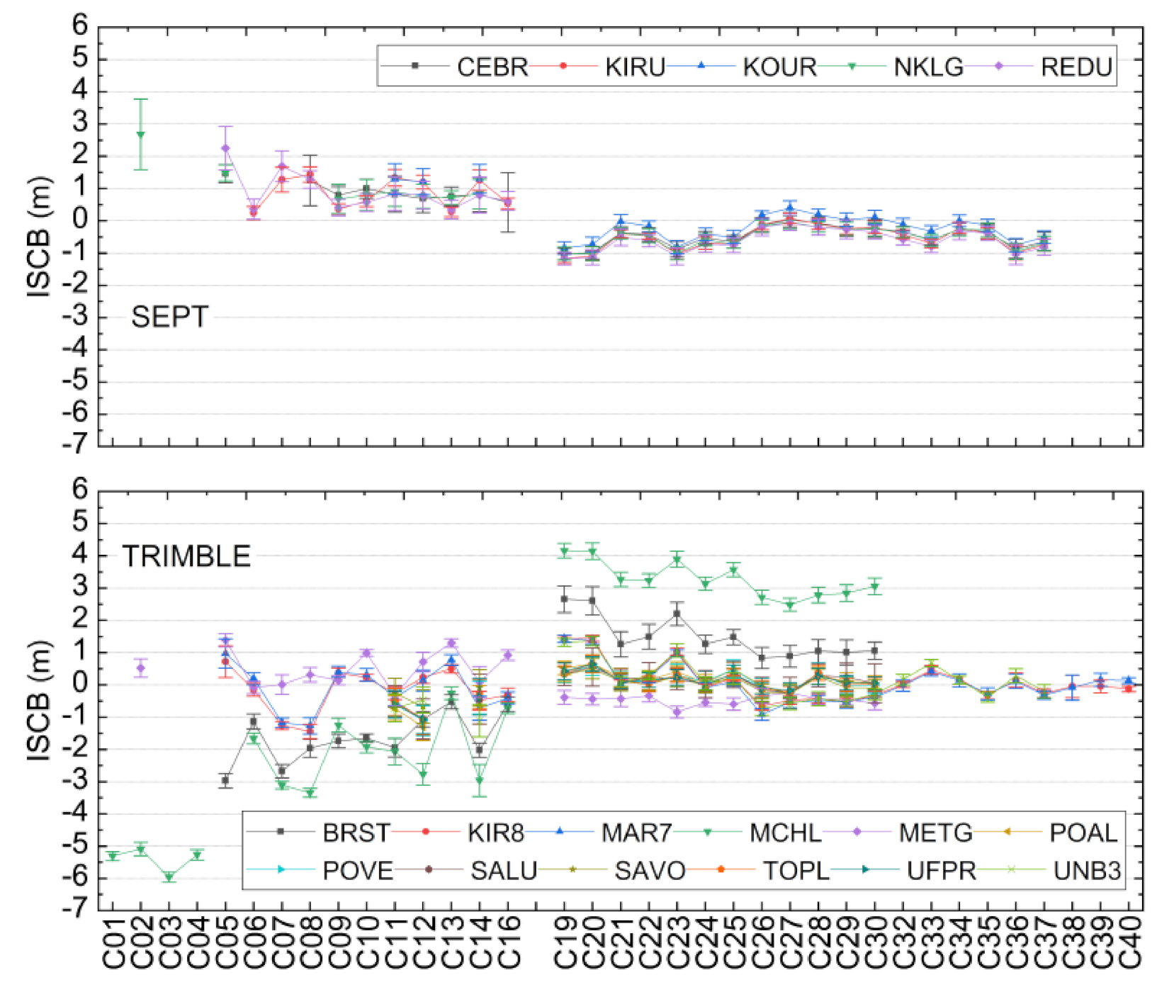
Figure 2 shows the average and stability of all of the BDS, 2 and BDS, 3 satellites’ ISCBs of Septentrio and Trimble in Figure 1 from DOY 335 to 365 of 2019, where the horizontal axis refers to the BDS, 2 and BDS, 3 satellites, the different marking lines represent the different receivers, and the error bars represent the ISCB STD values for those receivers. Based on Figure 2, it can be concluded that the ISCBs have a good consistency for the Septentrio devices, while the differences of the Trimble brand are relatively large and can be up to 6–8m, i.e., BRST and MCHL. It can be also found in Figure 2 that there is an obvious clustering phenomenon for the BDS, 2 and BDS, 3 satellites for all Septentrio receivers and some of the Trimble ones.
In an undifferenced model of a multi, GNSS fusion solution, the GPS observations are usually selected as the reference datum, while the ISB parameters actually mean that all of the computed code biases of the other systems are obtained relative to the biases for the GPS observations [25]. Thus, one receiver’s systematic bias of two clusters of BDS, 2 and BDS, 3 ISCBs are actually the ISB and can be calculated by the average of the BDS, 2 ISCBs and the BDS, 3 ISCBs, as per Equation (9).
I S B C 2 C 3 = i = 1 n C 2 I S C B i C 2 n C 2 i = 1 n C 3 I S C B i C 3 n C 3
Table 4 provides the statistics of the receivers of Septentrio and Trimble in Figure 1 and Table 2, including the average ISCB, the ISB between BDS, 2 and BDS, 3, and the STD. From the statistics provided by Table 4, the clustering code bias phenomenon become clearer. The ISCB cluster difference of the Septentrio devices were close, and the ISB of BDS2 and BDS, 3 was approximately 1.5 m. Meanwhile, there were significant differences among the Trimble devices, especially BRST and MCHL. The MCHL ISB of BDS2 and BDS, 3 was up to 6.3 m, which would seriously affect the positioning performance of the BDS, 2+3 joint solution based on B1I+B3I. From Table 4, we can also conclude that the STD of the BDS ISCB remained at decimeter level, worse than the centimeter level of GPS and Galileo [16], and the ISCBs of the BDS, 3 satellite were more stable than those of the BDS, 2 satellite.
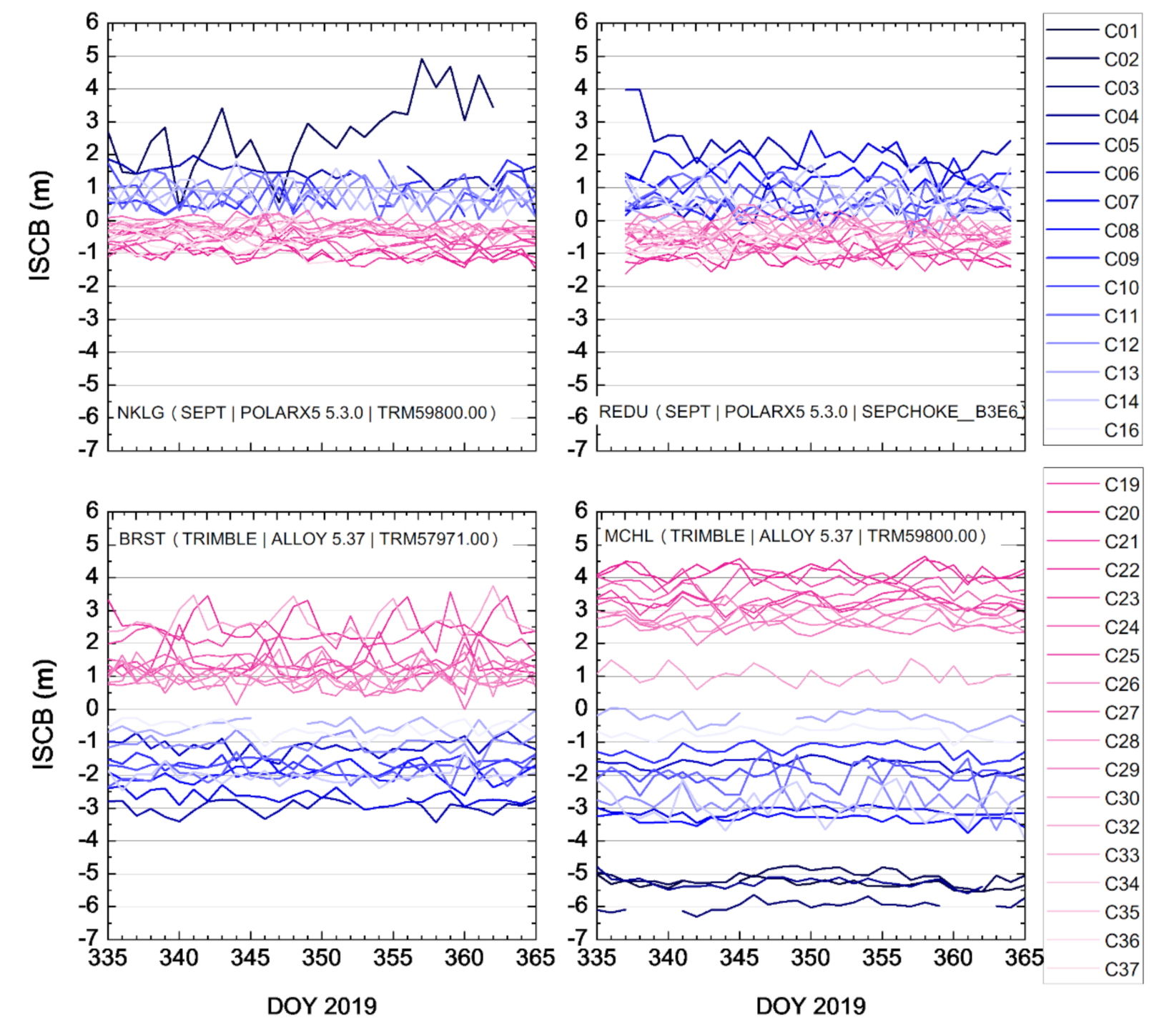
Aiming to identify the significant clustering code biases between BDS, 2 and BDS, 3, Figure 3 shows all of the BDS satellites’ ISCB time series of the part receivers of Septentrio (NKLG and REDU) and Trimble (BRST and MCHL) from DOY 335 to 365 of 2019. Among them, the blue, tone lines are the satellites of BDS, 2, while the red, tone lines are the satellites of BDS, 3. The two different color clusters show the clustering bias characteristics of BDS, 2 and BDS, 3 more clearly. Combining Figure 2 and Figure 3 and Table 4, it can be observed that there are some differences in the different manufacturers, receiver types, firmware, and antennas in terms of the BDS code bias characteristics. As Septentrio showed, some manufacturers have good consistency among devices, while some are irregular, such as Trimble.
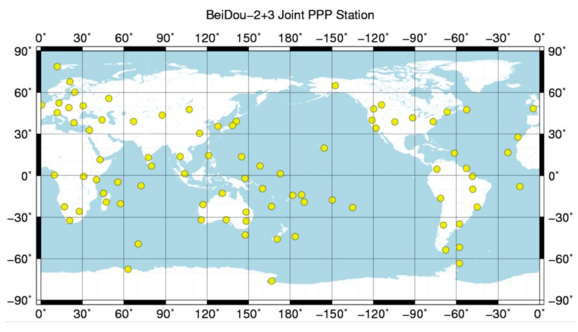
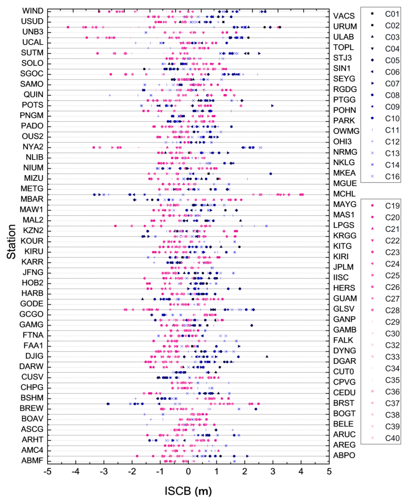
In order to verify the universality of the clustering code biases between BDS, 2 and BDS, 3, approximately 90 global BDS, 2 and BDS, 3 tracking stations were also selected, as shown in Figure 4. Figure 5 shows the distribution of these stations’ ISCBs for BDS, 2 and BDS, 3, as estimated with the additional constraint (4). Similar to Figure 3, the blue, tone marks in Figure 5 are the satellites of BDS, 2, while the red, tone marks are the BDS, 3 satellites. The results show the ISCB clustering phenomenon between BDS, 2 and BDS, 3 is universal in the individual stations. As per the analysis above, the differences in the average ISCB of the BDS, 2 and BDS, 3 satellites are also the ISB parameters estimated in the undifferenced model; therefore, systematic clustering biases should be considered in the BDS, 2+3 joint solution.
In combination with Figure 3, it is interesting to note that the code biases between BDS, 2 and BDS, 3 are opposite for the Septentrio and Trimble stations. The inconsistency in the phenomenon of inter, manufacturer code biases also exists in Figure 4, which was caused by manufacturers with different correlator types and front, end designs [3].

3.3. ISCB Time Variation Characteristics

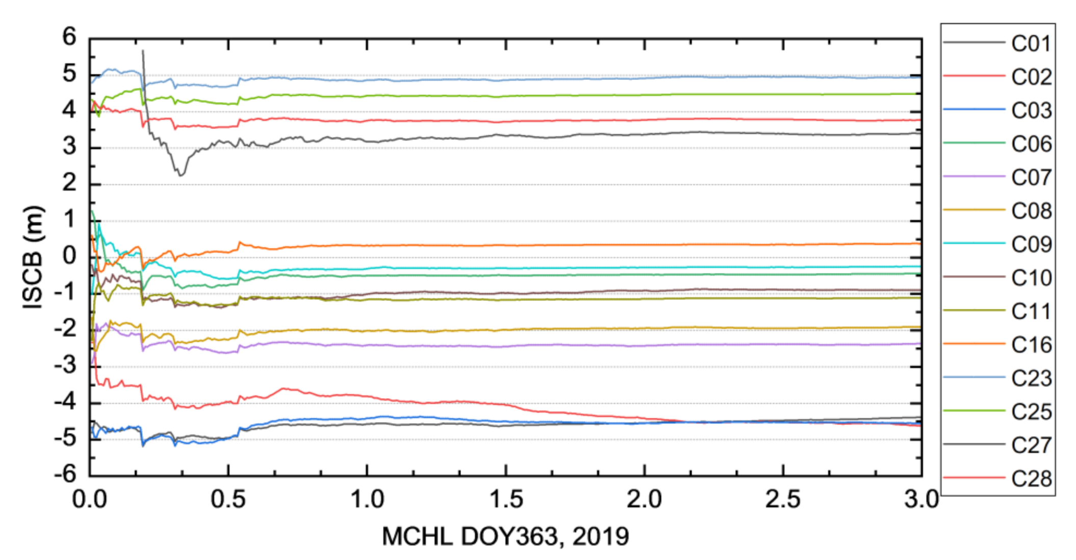
Figure 6 shows the time series of the BDS, 2 and BDS, 3 ISCBs for the MCHL station in the first three hours. As with the ambiguities for the carrier, phase observations, there was a significant convergence period (about 0.5 h) with the accumulation of observations, after which all of the ISCBs stabilized. Thus, these ISCBs can be applied to the self, calibrating code biases of the subsequent epoch.

4. Results and Discussion

4.1. Systematic Biases in the BDS, 2+3 Joint Solution

Those results above show that there is an obvious clustering code bias phenomenon between the BDS, 2 and BDS, 3 satellites, which leads to systematic biases existing in the BDS, 2+3 joint solution. Thus, based on the B1I+B3I signals, BDS, 2 and BDS, 3 should be regarded as two individual navigation satellite systems. According to multi, GNSS positioning theory, the ISB parameters should be added into observations [25,31].
By introducing ISB parameters into observations, they can absorb the shared systematic biases between BDS, 2 and BDS, 3, but cannot describe the dispersed clustering code biases between the BDS, 2 and BDS, 3 satellites accurately, which leads to unequal code biases in residuals, while individual ISCB parameters can avoid this. On account of relying on its own observations and ephemeris products with no other external products, the ISCB estimation algorithm above can realize ISCB self, calibration at a single station independently. Based on the stable ISCB, we propose the BDS, 2+3 joint solution with code bias self, calibration, using which we analyzed the residuals and positioning improvements.

4.2. BDS, 2+3 Joint Model with Code Bias Self-Calibration

Considering the existence of unequal receiver, dependent clustering code biases between BDS, 2 and BDS, 3, the linearized undifferenced observation (1) of the BDS, 2+3 joint solution is as follows:
v i , P s , C 2 t = u i s , C 2 d x + d t r t + b i , P , I S C B s , C 2 d t 0 i s , C 2 + M i s , C 2 z w d t l i , P s , C 2 t v i , Φ s , C 2 t = u i s , C 2 d x + d t r t d t 0 i s , C 2 + b i , Φ s , C 2 B j , Φ s , C 2 + N i s , C 2 + M i s , C 2 z w d t l i , Φ s , C 2 t v j , P s , C 3 t = u j s , C 2 d x + d t r t + b j , P , I S C B s , C 3 d t 0 j s , C 3 + M j s , C 3 z w d t l j , P s , C 3 t v j , Φ s , C 3 t = u j s , C 2 d x + d t r t d t 0 j s , C 3 + b j , Φ s , C 3 B j , Φ s , C 3 + N j s , C 3 + M j s , C 3 z w d t l j , Φ s , C 3 t
where C2 and C3 represent the BDS, 2 and BDS, 3 satellites, respectively; i and j are the i, th BDS, 2 satellite and j, th BDS, 3 at the t, th epoch; u is the unit vector from the receiver to the satellite direction; d x represents the receiver position incremental vector relative to the previous epoch.
Similarly to the ISCB estimation process, in the BDS, 2+3 joint model, considering clustering code biases, the parameters to be estimated mainly include position, clock offset, troposphere, the ISCB of each satellite, and the ambiguity parameters. The analyses above show that the receiver, dependent ISCB remains stable over a long time. Thus, the ISCBs estimated in the previous epoch can be applied to self, calibrating the clustering code biases of the subsequent epoch to achieve the synchronization of BDS, 2 and BDS, 3. Thus, (10) can be further simplified as follows:
v i , P s , C 2 t = u i s , C 2 d x + d t r t + M i s , C 2 z w d t l ˜ i , P s , C 2 t v i , Φ s , C 2 t = u i s , C 2 d x + d t r t + N ˜ i s , C 2 + M i s , C 2 z w d t l i , Φ s , C 2 t v j , P s , C 3 t = u j s , C 2 d x + d t r t + M j s , C 3 z w d t l ˜ j , P s , C 3 t v j , Φ s , C 3 t = u j s , C 2 d x + d t r t + N ˜ j s , C 3 + M j s , C 3 z w d t l j , Φ s , C 3 t
where l ˜ P s = l P s + I S C B s , N ˜ i s = N i s d t 0 i s + b i , Φ s B Φ s . ISCB can be obtained from (3).
From (11), the BDS, 2+3 joint model with code bias self, calibration just estimates the general parameters, such as the position, clock offset, troposphere, and ambiguity parameters, as follows:
X = d x 3 × 1 d t 1 × 1 z w d 1 × 1 N n S × 1
The pseudorange and carrier, phase observations are added into the observation equations, and then the t, th epoch linearized observation equation can be expressed as follows:
v t = A t X t + l ˜ t
where:
l ˜ t = l t + I S C B
where I S C B is the vector of the BDS, 2 and BDS, 3 satellites ISCBs:
A = B 2 n S × 3 1 2 n S × 1 M 2 n S × 1 0 n S × n S I n S × n S
where B 2 n S × 3 is the unit vector of each satellite in the position direction d x 3 × 1 .
From (11) and (14), the ISCBs obtained in previous epoch are used to correct the OMC of the BDS, 2 and BDS, 3 satellites, which not only resolves the systematic biases existing in BDS, 2+3, but also improves the pseudorange correction accuracy. Theoretically, with the improvement of the pseudorange correction accuracy, positioning performance will also be elevated.

4.3. Residual Analysis

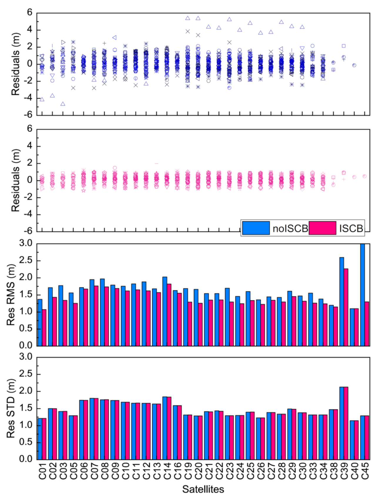
In order to analyze the effects of ISCB self, calibration on the BDS, 2+3 joint solution, we analyzed the pseudorange residuals based on the PPP results of the stations in Figure 4 from DOY 359 to 365 of 2019. Figure 7 shows a comparison of the PPP pseudorange residuals before and after ISCB self, calibration, where the horizontal axis refers to the BDS, 2 and BDS, 3 satellites, and the different marks in upper two sub, figures represent the residual distribution of all of the receivers in Figure 4 for one satellite. The blue, tone marks are the residuals with no ISCB self, calibration, while the red, tone marks are the residuals after ISCB self, calibration. The histograms of the third and fourth subfigures are the root mean square (RMS) and STD statistics of the pseudorange residuals with and without ISCB correction. The RMS and STD can be obtained as follows:
A V E s = i = 1 n s t a R E S i s n s t a S T D s = i = 1 n s t a R E S i s A V E s 2 n s t a 1 R M S s = i = 1 n s t a R E S i s 2 n s t a
where n s t a refers to the stations number of the residuals of the satellite s, AVE is the residuals average, STD is the standard deviation, and RMS is the root mean square.
From the results, compared to the uncalibrated BDS, 2+3 joint PPP, the ISCB self, calibration can further correct the pseudorange residuals to close to 0. The statistics show that the biases and RMS improved by 36% and 15%, respectively. However, the STD did not change significantly.

4.4. Improvements in BDS, 2+3 Joint PPP

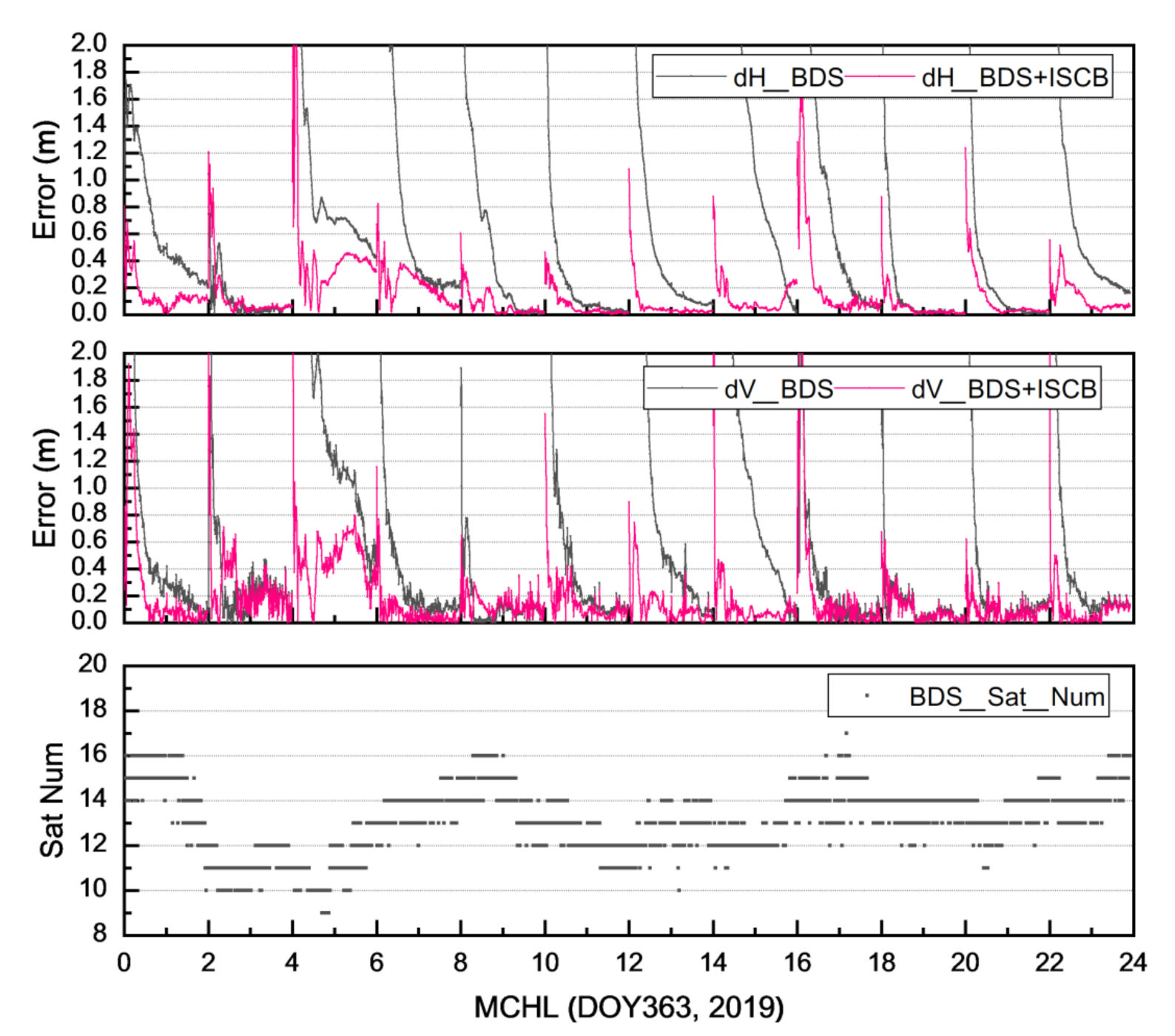
It was found from Equation (3) that the multi, GNSS ISCB real, time estimation algorithm for single stations proposed in this paper can accurately strip off the clustering code biases of BDS, 2 and BDS, 3 and the clock offset biases from pseudorange observations. We interrupted the BDS, 2+3 joint PPP experiment every 2 h to simulate the reconvergence process and used the ISCB estimated in the previous two hours to self, calibrate the pseudoranges of the subsequent epoch. Then, we analyzed the influence of the ISCB self, calibration on the BDS, 2+3 joint PPP. Figure 8 shows one station’s horizontal and vertical convergence comparison of the BDS, 2+3 joint PPP with and without ISCB self, calibration. The black line indicates the PPP results with no ISCB self, calibration, while the red line shows the PPP results after ISCB self, calibration. It can be seen from the figure that the convergence speed of the BDS, 2+3 joint PPP self, calibrated by ISCB significantly improved.
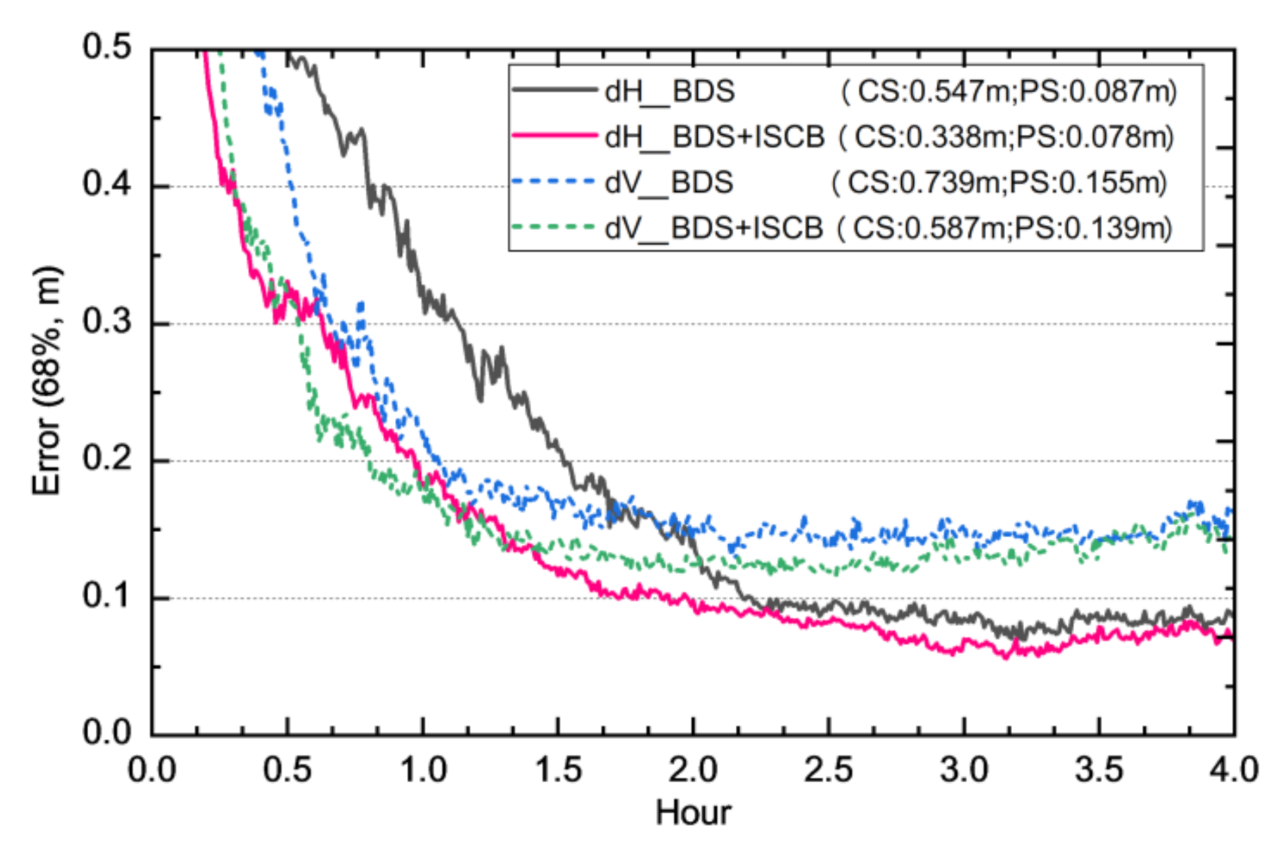
Based on the PPP results of DOY 359–365 of 2019 of the stations in Figure 6, the 68% accuracy of each epoch in the convergence stage was analyzed, and a comparison of the accuracy is shown in Figure 9 (convergence condition was 10 cm in the horizontal direction and 20 cm in the vertical direction). Table 5 shows convergence comparisons and improvements in the different convergence conditions of BDS, 2+3 joint PPP with and without ISCB self, calibration. It can be seen from Figure 9 and Table 5 that ISCB self, calibration improved the convergence speed and accuracy of BDS, 2+3 joint PPP greatly. The convergence time to 10 cm in the horizontal direction reduced from 133 min to approximately 100 min, while the convergence time to 20 cm in the vertical reduced from 64 min to approximately 48.5 min. As can be seen in Table 5, the convergence time improved by approximately 42% and 28% in the horizontal and vertical directions, respectively. In addition, ISCB self, calibration significantly improved the BDS, 2+3 joint PPP accuracy in the convergence and post, convergence stages. In the convergence stage, the accuracy improved by approximately 38% and 21% in the horizontal and vertical directions, respectively. Meanwhile, in the post, convergence stage, the accuracy improved by approximately 10% in both the horizontal and vertical directions.

5. Conclusions

For reasons mostly related to chip shape distortions, GNSS observations are corrupted by receiver, dependent code biases. Receiver, dependent ISCB and clock offset biases are brought into observation residuals, which degrades the pseudorange correction accuracy. Aiming to determine the receiver, dependent code biases, we presented a navigation signal ISCB estimation algorithm and analyzed the clustering code bias characteristics of BDS, 2 and BDS, 3. Then, we proposed a BDS, 2 and BDS, 3 ISCB self, calibration method for single, station and effects analysis of the BDS, 2+3 joint solution. The results were as follows:
  • The ISCB real, time estimation algorithm for single stations presented in this paper accurately stripped off the receiver, dependent ISCB and clock offset biases from the pseudorange observations simultaneously.
  • We analyzed the ISCB characteristics of BDS, 2 and BDS, 3 based on the B1I + B3I signal and found there to be an obvious clustering code bias phenomenon between the BDS, 2 and BDS, 3 satellites, leading to systematic biases existing in the BDS, 2+3 joint solution.
  • We proposed the BDS, 2+3 joint solution with code bias self, calibration, which can accurately strip off clustering code biases between the BDS, 2 and BDS, 3 satellites and can greatly improve the PPP convergence speed and accuracy.
  • The statistics showed that the residual biases and RMS of BDS, 2+3 joint PPP improved by 36% and 15%, respectively, and the convergence time improved by approximately 35%. In the convergence stage, the positioning accuracy improved by approximately 38% and 21% in the horizontal and vertical directions, respectively.
Meanwhile, in the post, convergence stage, the accuracy improved by approximately 10%.

Author Contributions

Conceptualization, L.C. and F.Z.; methodology, M.L. and C.S.; software, L.C; validation, F.Z.; writing—original draft preparation, L.C and Y.Z.; writing—review and editing, F.Z. and M.L.; visualization, L.C; supervision, C.S. and X.Z.; funding acquisition, C.S. All authors have read and agreed to the published version of the manuscript.

Funding

This research is sponsored by Shanghai Key Laboratory of Space Navigation and Positioning Techniques (201901), Youth Program of National Natural Science Foundation of China (42004026), National Natural Science Foundation of China (42030109, 42074032), and Wuhan Science and Technology Bureau (2019010701011391).

Acknowledgments

Thanks to the multi, GNSS high, precision products provided by GFZ and GNSS Data provided by IGS. The authors would like to thank the editor in chief and the anonymous reviewers for their valuable comments and improvements to this manuscript.

Conflicts of Interest

The authors declare no conflict of interests.

References

  1. Coco, D.; Coker, C.; Dahlke, S.; Clynch, J. Variability of GPS Satellite Differential Group Delay Biases. IEEE Trans. Aerosp. Electron. Syst. 1991, 27, 931–938. [Google Scholar] [CrossRef]
  2. Sardón, E.; Zarraoa, N. Estimation of total electron content using GPS data: How stable are the differential satellite and receiver instrumental biases. Radio Sci. 1997, 32, 1899–1910. [Google Scholar] [CrossRef]
  3. Hauschild, A.; Montenbruck, O. A Study on the Dependency of GNSS Pseudorange Biases on Correlator Spacing. GPS Solut. 2016, 20, 159–171. [Google Scholar] [CrossRef]
  4. Montenbruck, O.; Steigenberger, P.; Prange, L.; Deng, Z.; Zhao, Q.; Perosanz, F.; Romero, I.; Noll, C.E.; Stürze, A.; Weber, G.; et al. The multi, GNSS experiment (MGEX) of the international GNSS service (IGS), achievements, prospects and challenges. Adv. Space Res. 2017, 59, 1671–1697. [Google Scholar] [CrossRef]
  5. Schaer, S.; Gurtner, W.; Feltens, J. IONEX: The Ionosphere Map Exchange Format Version 1. In Proceedings of the IGS AC Workshop, Darmstadt, Germany, 9–11 February 1998. [Google Scholar]
  6. Hauschild, A.; Steigenberger, P.; Montenbruck, O. Inter, Receiver GNSS Pseudorange Biases and Their Effect on Clock and DCB Estimation. In Proceedings of the ION GNSS+ 2019, Institute of Navigation, Miami, FL, USA, 16–20 September 2019; pp. 3675–3685. [Google Scholar]
  7. He, C.; Lu, X.; Guo, J.; Su, C.; Wang, W.; Wang, M. Initial analysis for characterizing and mitigating the pseudorange biases of BeiDou navigation satellite system. Satell. Navig. 2020, 1, 3. [Google Scholar] [CrossRef] [Green Version]
  8. Collins, P.; Lahaye, F.; Heroux, P.; Bisnath, S. Precise point positioning with ambiguity resolution using the decoupled clock model. In Proceedings of the ION GNSS 2008, Institute of Navigation, Savannah, GA, USA, 16–19 September 2008; pp. 1315–1322. [Google Scholar]
  9. Laurichesse, D.; Mercier, F.; Berthias, J.P.; Broca, P.; Cerri, L. Integer ambiguity resolution on undifferenced GPS phase measurements and its application to PPP and satellite precise orbit determination. Navigation 2009, 56, 135–149. [Google Scholar] [CrossRef]
  10. Geng, J.; Teferle, F.; Meng, X.; Dodson, A. Towards PPP, RTK: Ambiguity resolution in real, time precise point positioning. Adv. Space Res. 2010, 47, 1664–1673. [Google Scholar] [CrossRef] [Green Version]
  11. Zhang, B.; Odijk, P.; Teunissen, D. A novel un, differenced PPP, RTK concept. J. Navig. 2011, 64, 180–191. [Google Scholar] [CrossRef] [Green Version]
  12. Ge, M.; Gendt, G.; Rothacher, M.; Shi, C.; Liu, J. Resolution of GPS carrier phase ambiguities in precise point positioning (PPP) with daily observations. J. Geod. 2008, 82, 389–399. [Google Scholar] [CrossRef]
  13. Geng, J.; Meng, X.; Dodson, A.; Teferle, F. Integer ambiguity resolution in precise point positioning: Method comparison. J. Geod. 2010, 84, 569–581. [Google Scholar] [CrossRef] [Green Version]
  14. Hauschild, A.; Montenbruck, O. The Effect of Correlator and Front, End Design on GNSS Pseudorange Biases for Geodetic Receivers. Navig. J. Inst. Navig. 2016, 63, 443–453. [Google Scholar] [CrossRef]
  15. Chen, L.; Li, M.; Hu, Z.; Fang, C.; Geng, C.; Zhao, Q.; Shi, C. Method for real, time self, calibrating GLONASS code inter, frequency bias and improvements on single point positioning. GPS Solut. 2018, 22, 111. [Google Scholar] [CrossRef]
  16. Shi, C.; Yi, W.; Song, W.; Lou, Y.; Yao, Y.; Zhang, R. GLONASS pseudorange inter, channel biases and their effects on combined GPS/GLONASS precise point positioning. GPS Solut. 2013, 17, 439–451. [Google Scholar]
  17. Cai, C.; Luo, X.; Liu, Z.; Xiao, Q. Galileo Signal and PositioningPerformance Analysis Based onFour IOV Satellites. J. Navig. 2014, 67, 810–824. [Google Scholar] [CrossRef] [Green Version]
  18. Zhao, Q.; Guo, J.; Li, M.; Qu, L.; Hu, Z.; Shi, C.; Liu, J. Initial results of precise orbit and clock determination for COMPASS navigation satellite system. J. Geod. 2013, 87, 475–486. [Google Scholar] [CrossRef]
  19. Lou, Y.; Liu, Y.; Shi, C.; Yao, X.; Zheng, F. Precise orbit determination of BeiDou constellation based on BETS and MGEX network. Sci. Rep. 2014, 4, 4692. [Google Scholar] [CrossRef] [Green Version]
  20. Zhao, Q.; Wang, C.; Guo, J.; Wang, B.; Liu, J. Precise orbit and clock determination for BeiDou, 3 experimental satellites with yaw attitude analysis. GPS Solut. 2018, 22, 4. [Google Scholar] [CrossRef] [Green Version]
  21. CSNO. Development of the BeiDou Navigation Satellite System (Version 4.0); China Satellite Navigation Office: Beijing, China, 2019. Available online: http://www.beidou.gov.cn/xt/gfxz/201912/P020191227430565455478.pdf (accessed on 1 November 2020).
  22. Chen, J.; Hu, X.; Tang, C.; Zhou, S.; Yang, Y.; Pan, J.; Ren, H.; Ma, Y.; Tian, Q.; Wu, B.; et al. SIS accuracy and service performance of the BDS, 3 basic system. Sci. China Phys. Mech. Astron. 2020, 63, 269511. [Google Scholar] [CrossRef]
  23. Dai, P.; Ge, Y.; Qin, W.; Yang, X. BDS, 3 Time Group Delay and Its Effect on Standard Point Positioning. Remote Sens. 2019, 11, 1819. [Google Scholar] [CrossRef] [Green Version]
  24. Tang, C.; Su, X.; Hu, X.; Gao, W.; Liu, L.; Lu, J.; Chen, Y.; Liu, C.; Wang, W.; Zhou, S. Characterization of pesudorange bias and its effect on positioning for BDS satellites. Acta Geod. Cartogr. Sin. 2020, 49, 1131–1138. [Google Scholar]
  25. Li, X.; Ge, M.; Dai, X.; Ren, X.; Fritsche, M.; Wickert, J.; Schuh, H. Accuracy and reliability of multi, GNSS real, time precise positioning: GPS, GLONASS, BeiDou, and Galileo. J. Geod. 2015, 89, 607–635. [Google Scholar] [CrossRef]
  26. Teunissen, P.; Montenbruck, O. Handbook of GNSS; Springer Nature: Cham, Switzerland, 2017. [Google Scholar]
  27. Dach, R.; Schaer, S.; Hugentobler, U. Combined multi, system GNSS analysis for time and frequency transfer. In Proceedings of the 20th European Frequency and Time Forum EFTF06, Braunschweig, Germany, 27–30 March 2006; pp. 530–537. [Google Scholar]
  28. Rebischung, P.; Schmid, R. IGS14/igs14.atx: A new framework for the IGS products. In Proceedings of the American Geophysical Union Fall Meeting, San Francisco, CA, USA, 12–16 December 2016. [Google Scholar]
  29. Dilssner, F.; Springer, T.; Schönemann, E.; Enderle, W. Estimation of Satellite Antenna Phase Center Corrections for BeiDou. In Proceedings of the IGS Workshop 2014, Pasadena, CA, USA, 23–27 June 2014. [Google Scholar]
  30. Bierman, G. Factorization Methods for Discrete Sequential Estimation; Academic Press Inc.: New York, NY, USA, 1977. [Google Scholar]
  31. Chen, L.; Zhao, Q.; Hu, Z.; Ge, M.; Shi, C. GNSS global real, time augmentation positioning: Real, time precise satellite clock estimation, prototype system construction and performance analysis. Adv. Space Res. 2018, 61, 367–384. [Google Scholar] [CrossRef]
Figure 1. Distribution of experiment stations. SEPT, Septentrio.
Remotesensing 13 00015 g001
Figure 2. Average and stability of the BDS, 2 and BDS, 3 satellites’ inter, satellite code biases (ISCBs) of Septentrio and Trimble.
Remotesensing 13 00015 g002
Figure 3. BDS, 2 and BDS, 3 ISCB clustering of Septentrio (NKLG and REDU) and Trimble (BRST and MCHL).
Remotesensing 13 00015 g003
Figure 4. Station distribution of the BDS, 2+3 joint precise point positioning (PPP) test.
Remotesensing 13 00015 g004
Figure 5. BDS, 2 and BDS, 3 ISCBs clustering for the 90 stations chosen.
Remotesensing 13 00015 g005
Figure 6. Time series of the BDS, 2 and BDS, 3 ISCBs for the MCHL station in the first three hours.
Remotesensing 13 00015 g006
Figure 7. Comparison of the BDS, 2+3 pseudorange residuals before and after ISCB self, calibration. RMS, root mean square.
Remotesensing 13 00015 g007
Figure 8. A comparison of the horizontal and vertical convergence of BDS, 2+3 joint PPP with and without ISCB self, calibration of MCHL on day of year (DOY) 363 of 2019.
Remotesensing 13 00015 g008
Figure 9. BDS, 2+3 joint PPP comparison with and without ISCB self, calibration. CS, convergence stage accuracy; PS, post, convergence stage accuracy.
Remotesensing 13 00015 g009
Table 1. The BeiDou navigation satellite system (BDS) satellite’s information (www.csno-tarc.cn/en/system/constellation, up to June 2020).
PRNSVNNORAD IDSVNSystemManufactureNotes(UTC)Civil Signal
C01C02044231GEO-8BDS-2CAST17 May, 2019B1I/B2I/B3I
C02C01638953GEO-6BDS-2CAST25 Oct, 2012B1I/B2I/B3I
C03C01841586GEO-7BDS-2CAST12 June, 2016B1I/B2I/B3I
C04C00637210GEO-4BDS-2CAST1 Nov, 2010B1I/B2I/B3I
C05C01138091GEO-5BDS-2CAST25, Feb, 2012B1I/B2I/B3I
C06C00536828IGSO, 1BDS, 2CAST1, Aug, 2010B1I/B2I/B3I
C07C00737256IGSO, 2BDS, 2CAST18, Dec, 2010B1I/B2I/B3I
C08C00837384IGSO, 3BDS, 2CAST10, Apr, 2011B1I/B2I/B3I
C09C00937763IGSO, 4BDS, 2CAST27, Jul, 2011B1I/B2I/B3I
C10C01037948IGSO, 5BDS, 2CAST2, Dec, 2011B1I/B2I/B3I
C11C01238250MEO, 3BDS, 2CAST30, Apr, 2012B1I/B2I/B3I
C12C01338251MEO, 4BDS, 2CAST30, Apr, 2012B1I/B2I/B3I
C13C01741434IGSO, 6BDS, 2CAST30, Mar, 2016B1I/B2I/B3I
C14C01538775MEO, 6BDS, 2CAST19, Sep, 2012B1I/B2I/B3I
C16C01943539IGSO, 7BDS, 2CAST10, Jul, 2018B1I/B2I/B3I
C19C20143001MEO, 1BDS, 3CAST5, Nov, 2017B1I/B3I/B1C/B2a/B2b
C20C20243002MEO, 2BDS, 3CAST5, Nov, 2017B1I/B3I/B1C/B2a/B2b
C21C20643208MEO, 3BDS, 3CAST12, Feb, 2018B1I/B3I/B1C/B2a/B2b
C22C20543207MEO, 4BDS, 3CAST12, Feb, 2018B1I/B3I/B1C/B2a/B2b
C23C20943581MEO, 5BDS, 3CAST29, Jul, 2018B1I/B3I/B1C/B2a/B2b
C24C21043582MEO, 6BDS, 3CAST29, Jul, 2018B1I/B3I/B1C/B2a/B2b
C25C21243603MEO, 11BDS, 3SECM24, Aug, 2018B1I/B3I/B1C/B2a/B2b
C26C21143602MEO, 12BDS, 3SECM24, Aug, 2018B1I/B3I/B1C/B2a/B2b
C27C20343107MEO, 7BDS, 3SECM12, Jan, 2018B1I/B3I/B1C/B2a/B2b
C28C20443108MEO, 8BDS, 3SECM12, Jan, 2018B1I/B3I/B1C/B2a/B2b
C29C20743245MEO, 9BDS, 3SECM29, Mar, 2018B1I/B3I/B1C/B2a/B2b
C30C20843246MEO, 10BDS, 3SECM29, Mar, 2018B1I/B3I/B1C/B2a/B2b
C32C21343622MEO, 13BDS, 3CAST19, Sep, 2018B1I/B3I/B1C/B2a/B2b
C33C21443623MEO, 14BDS, 3CAST19, Sep, 2018B1I/B3I/B1C/B2a/B2b
C34C21643648MEO, 15BDS, 3SECM15, Oct, 2018B1I/B3I/B1C/B2a/B2b
C35C21543647MEO, 16BDS, 3SECM15, Oct, 2018B1I/B3I/B1C/B2a/B2b
C36C21843706MEO, 17BDS, 3CAST18, Nov, 2018B1I/B3I/B1C/B2a/B2b
C37C21943707MEO, 18BDS, 3CAST18, Nov, 2018B1I/B3I/B1C/B2a/B2b
C38C22044204IGSO, 1BDS, 3CAST20, Apr, 2019B1I/B3I/B1C/B2a/B2b
C39C22144337IGSO, 2BDS, 3CAST24, Jun, 2019B1I/B3I/B1C/B2a/B2b
C40C22444709IGSO, 3BDS, 3CAST4, Nov, 2019B1I/B3I/B1C/B2a/B2b
C41C22744864MEO, 19BDS, 3CAST16, Dec, 2019B1I/B3I/B1C/B2a/B2b
C42C22844865MEO, 20BDS, 3CAST16, Dec, 2019B1I/B3I/B1C/B2a/B2b
C43C22644794MEO, 21BDS, 3SECM23, Nov, 2019B1I/B3I/B1C/B2a/B2b
C44C22544793MEO, 22BDS, 3SECM23, Nov, 2019B1I/B3I/B1C/B2a/B2b
C45C22344543MEO, 23BDS, 3CAST22, Sep, 2019B1I/B3I/B1C/B2a/B2b
C46C22244542MEO, 24BDS, 3CAST22, Sep, 2019B1I/B3I/B1C/B2a/B2b
C59C21743683GEO, 1BDS, 3CAST1, Nov, 2018B1I/B3I
C60C22945344GEO, 2BDS, 3CAST9, Mar, 2020B1I/B3I
C61C23045807GEO, 3BDS, 3CAST23, Jun, 2020B1I/B3I
PRN, Pseudo, Random Noise; SVN, space vehicle number; GEO, Geostationary Earth Orbit; IGSO, Inclined Geosynchronous Satellite Orbit; MEO, Medium Earth Orbit; CAST, China Academy of Space Technology (CAST); SECM, Shanghai Engineering Center for Microsatellites.
Table 2. Experimental site information (October to December 2019).
ManufacturerTypeFirmwareAntennaSiteBDS Signal
SeptentrioPOLARX5TR5.3.0SEPCHOKE_B3E6CEBRB1I/B2I/B3I
POLARX55.3.0SEPCHOKE_B3E6KIRU, KOUR, REDU
TRM59800.00NKLG
TrimbleALLOY5.37
5.37
TRM57971.00BRSTB1I/B2I/B3I
TRM59800.00MCHL
5.42TRM57971.00UNB3
5.43LEIAR25.R3KIR8, MAR7
NETR95.42TRM59800.00METG
TRM115000.00POAL, POVE, SALU,
SAVO, TOPL, UFPR
Table 3. Processing strategy, model, and parameters of the inter, satellite code bias (ISCB) estimation.
ParametersModel
ObservationsUD IF pseudorange/carrier phase
Prior informationPseudorange 1.0 m; carrier phase 0.02 cycles
Cut, off elevation
Observation weightsp = 1, elev. >30° p = 2sin(elev.), elev. ≤30°
Interval30s
PCO/PCVSatelliteGPS, Galileo PCO: IGS14.atx [28];
BDS, 2 GEO PCO: IGS M, GEX;
BDS, 2 IGSO/MEO PCO: ESA Mode [29];
BDS, 3 MEO: www.beidou.gov.cn
GPS PCV: IGS14.atx; BDS, Galileo PCV: Uncorrected
ReceiverGPS PCO: IGS14.atx; BDS, Galileo PCO: Same as GPS;
GPS PCV: IGS14.atx; BDS, Galileo PCV: Same as GPS
Adjustment methodSquare root information filtering [30]
Troposphere delaySaastamoinen model + GMF mapping function random, walk process for each epoch
Receiver clock offsetEstimated as white noise
AmbiguityFloat
ISCBConstant estimation with zero, mean condition every day [25]
UD, Undifferenced; IF, Ionospheric-Free; PCO, Phase Center Offset; PCV, Phase Center Variation; ESA, Europe Space Agency; ISCB, Inter-Satellite Code Bias.
Table 4. The average ISCBs of BDS, 2 and BDS, 3 and the inter, system bias (ISB) and standard deviation (STD) of the Septentrio and Trimble receivers (m).
ManufacturerStationISCB AverageISB between
BDS, 2 and BDS, 3
ISCB STD
BDS, 2BDS, 3BDS, 2BDS, 3
SeptentrioCEBR0.906−0.4761.3820.4770.191
KIRU0.853−0.5341.3870.2100.153
KOUR1.267−0.2481.5150.4170.197
REDU0.905−0.6121.5170.3830.225
NKLG1.105−0.5151.6200.5230.191
Average1.007−0.4771.4840.4020.191
TrimbleBRST−1.6641.484−3.1480.2170.340
MCHL−2.9793.276−6.2550.2320.202
UNB3−0.7660.142−0.9070.3250.163
KIR8−0.1680.091−0.2590.2080.135
MAR7−0.1060.069−0.1760.2450.166
METG0.497−0.4670.9640.2330.176
POAL−0.8850.223−1.1080.4180.255
POVE−0.6860.172−0.8580.4160.289
SALU−0.6690.167−0.8360.5510.427
SAVO−0.3390.085−0.4240.4780.244
TOPL−0.6330.158−0.7920.4080.211
UFPR−0.6830.171−0.8540.4290.225
Average−0.7570.464−1.2210.3470.236
Table 5. Convergence comparisons and improvements in the different convergence conditions of BDS, 2+3 joint PPP with and without ISCB self, calibration.
ModelConvergence ConditionAverage
40 cm30 cm20 cm10 cm
Convergence time in the horizontal direction (min)BDS526891.5133/
BDS+ISCB18.53858.599.5/
Improvement rate64%44%36%25%42%
Convergence time in the vertical direction (min)BDS31.54064//
BDS+ISCB18.532.548.5//
Improvement rate41%19%24%/28%
Publisher’s Note: MDPI stays neutral with regard to jurisdictional claims in published maps and institutional affiliations.