Abstract
The paper presents the results of probing the stable atmospheric boundary layer in the coastal zone of Lake Baikal with a coherent Doppler wind lidar and a microwave temperature profiler. Two-dimensional height–temporal distributions of the wind velocity vector components, temperature, and parameters characterizing atmospheric stability and wind turbulence were obtained. The parameters of the low-level jets and the atmospheric waves arising in the stable boundary layer were determined. It was shown that the stable atmospheric boundary layer has an inhomogeneous fine scale layered structure characterized by strong variations of the Richardson number Ri. Layers with large Richardson numbers alternate with layers where Ri is less than the critical value of the Richardson number Ricr = 0.25. The channels of decreased stability, where the conditions are close to neutral stratification 0 < Ri < 0.25, arise in the zone of the low-level jets. The wind turbulence in the central part of the observed jets, where Ri > Ricr, is weak, increases considerably to the periphery of jets, at heights where Ri < Ricr. The turbulence may intensify at the appearance of internal atmospheric waves.
1. Introduction
The processes of the origination and the evolution of turbulence in stably stratified media remain poorly understood in many areas of geophysics. This also applies to the atmosphere and its boundary layer, in which thermodynamic processes play an important role in the formation of weather and climate and affect the efficiency of wind power engineering and aviation safety. The Kolmogorov–Obukhov–Monin theory of isotropic turbulence is used successfully for the description of an unstable and neutrally stratified atmospheric boundary layer (ABL) [1,2]. However, the stably stratified ABL is poorly parameterizable based on this theory [3,4,5,6,7,8]. The mechanism of turbulence generation in the ABL under stable stratification remains unclear yet. Wave processes may play a critical part in this mechanism, and this determines the urgency of the studies of the wave–turbulence interaction in a stable ABL [9,10].
Remote sensing methods are now widely used in experimental studies of the atmosphere, as they allow for meteorological and optical data to be obtained in real time with the required space and time resolution. To study wind fields and wind turbulence in the atmospheric boundary layer and the lower troposphere, coherent Doppler wind lidars are the most suitable. The lidar methods and results of the lidar studies of the ABL, the height of the turbulent mixing layer at different temperature stratifications, and the different types of underlying surfaces are discussed in the literature [11,12,13,14,15]. The capabilities of the lidar methods in the studies of wind turbulence and the results of their testing in atmospheric experiments are discussed in the literature [16,17,18,19,20,21,22,23,24,25,26,27].
Stable stratification in the boundary layer is characterized by the formation of low-level jets (LLJs) and atmospheric waves. Sodars are applied for experimental studies of LLJs, particularly in the work of [28,29], which provides data on the repetition frequency and the wind parameters of LLJs. The results of the lidar studies of LLJs are reported in the literature [30,31,32,33]. In those papers, the vertical profiles of the mean wind and the variance of fluctuations of the longitudinal component of the wind velocity vector at heights of LLJ formation are retrieved from the data measured by the 2 µm pulsed coherent Doppler lidar (PCDL). Lidar and sodar studies of atmospheric waves in the stable boundary layer were carried out, in particular, by the authors of [30,34,35,36,37].
Many works have been devoted to developing the theory of turbulence in a stably stratified media (e.g., [38,39,40,41,42]). Works devoted to the stably stratified atmosphere are intended, for the most part, to study the mesoscale fluctuations of the wind velocity and the temperature in the stratosphere and the upper troposphere. It is shown that the upper atmosphere is characterized by the formation of the finescale layered inhomogeneities of velocity and temperature (e.g., [38], and the references in [38]). Fewer theoretical works are devoted to study of the structure of a stable ABL. Despite the obtained theoretical results and a large number of works devoted to experimental lidar studies of the atmospheric boundary layer [16,17,18,19,20,21,22,23,24,25,26,27], it remains unclear whether the stable boundary layer of the atmosphere has a layered structure such as that of the upper atmosphere.
One of the parameters characterizing the stability of the boundary layer is the Richardson number [4]. The time–altitude distributions of the Richardson number characterize the spatial structure and the dynamics of the stability of the boundary layer. The behavior of the Richardson number may reveal whether the stable boundary layer of the atmosphere has a layered structure or not. For studying of the variations of the Richardson number with height, the sodars are widely used. Examples of the vertical profiles of the Richardson number in the stably stratified atmosphere obtained with the use of sodars can be found in works [43,44,45,46]. Because of limitations in height, the sodars data refer to the lower atmospheric boundary layer within the first several hundreds of meters. The radio acoustic sounding systems provide measurements at higher altitudes [47].
In this paper, we present the results of the experiments on the wind–temperature probing the stable ABL. The goal of the experiments was to study the behavior of the Richardson number in the boundary layer and relate the spatial structure of wind velocity turbulence at the heights of formation of the LLJs and the internal atmospheric waves with the regimes of thermal stability in the ABL. For that, in the measurements, we employed coherent Doppler wind lidar concurrently with a microwave temperature profiler. As a result, we succeeded in not only obtaining data on the wind processes but also, in contrast to the lidar experiments on ABLs [16,17,18,19,20,21,22,23,24,25,26,27], relating them with the temperature regime in the ABL.
2. Methodology
The experiments were carried out in the coastal zone at the western coast of Lake Baikal near the coastal border of the mountain range. A map of the site of measurements is shown in Figure 1. Lake Baikal is at the altitude 456 meters above sea level. Thus, as it can be seen from Figure 1 (left), the measurement site is located among coastal hills 150–350 meters high above the level of Baikal. The choice of measurement location was determined by two reasons. First, we expected that the stable stratification in this region in summer should be observed not only at night as it occurs over the land surface but also during the day because of the low temperature of water in Lake Baikal. Second, we expected that the coastal mountain range would provide the conditions for more frequent formation of LLJs and internal atmospheric waves than occurs over plane land surface.
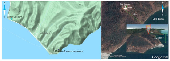
Figure 1.
Map of the site of measurements.
The wind lidar and the temperature profiler were installed at a distance of 340 m from Lake Baikal at a height of 180 m above the water surface at the territory of Astrophysical Observatory of the Institute of Solar-Terrestrial Physics SB RAS near Listvyanka, Russia (52°50’47’’ N, 104°53’31’’ E). Location of the devices is shown in Figure 1 (right). Measurements were conducted continuously during 6–23 August 2018.
2.1. Lidar Measurements of Radial Velocity and Estimation of Wind Turbulence Parameters
The measurements of radial velocity (projection of the wind velocity vector onto the probing beam axis) by the Stream Line wind lidar (Halo Photonics, Brockamin, Worcester, United Kingdom) were conducted using conical scanning with a probing beam around the vertical axis under an elevation angle of = 60° (Figure 1(right), Figure 2). In most cases, the probing beam was focused to a distance of 500 m. The duration of every scan was = 36 s. For the accumulation of raw lidar data, = 3000 laser shots were used. The pulse repetition frequency was = 15 kHz. Thus, the duration of the measurements for every azimuth angle was = 0.2 s. The azimuth resolution was = 360°/M = 2°, where M = / = 180 is the number of rays per scan. As a result of the measurements, we obtained arrays of estimates of the signal-to-noise ratio and the radial velocity . Here, is the ratio of the average heterodyne signal power to the noise power in a 50 MHz bandwidth, and the radial velocity is a projection of the wind vector onto the optical axis of the probing beam. The estimates of and are functions of the parameters and n, where is the distance from the lidar to the center of the sensing volume, , = 30 m is the range gate length, is the azimuth angle, and N is the scan number.
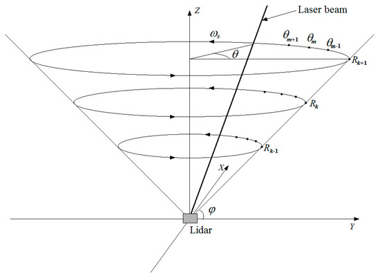
Figure 2.
Geometry of the conical scanning by the lidar probing beam.
The arrays of estimates of the radial velocities were used to restore the vertical profiles of the wind velocity vector , where is the vertical component, and and are the horizontal components of the velocity vector, by the sine wave fitting method [16]. The estimates of wind velocity vector by this method from data of the lidar sample used in this experiment were validated earlier against radiosonde [48] and sonic anemometers [21] data.
As a result, we obtained the spatiotemporal distributions of the horizontal wind velocity and direction and the vertical wind velocity for = 30 height levels from = 91 m to = 844 m for the relative height of the lidar location at time moments , with a resolution of = 26 m in height and = 36 s in time. The lower height is 91 m because the PCDL Stream Line (Halo Photonics, Brockamin, Worcester, United Kingdom) has a dead zone of about one hundred meters. The obtained values of the wind velocity vector are the results of averaging ([16]) the radial velocity estimates over the scan time = 36 s and along the circle of the base of scan cone with a length of = 330 m at a height of = 91 m and 3061 m at a height of = 844 m.
To estimate the wind turbulence parameters (turbulent energy dissipation rate , variance of fluctuations of the radial velocity , and integral scale of turbulence ) from the array of lidar estimates of the radial velocity , we used the method of the azimuth structure function (ASF) [16,17,21,26,27,35]. To restore the vertical profiles of the wind turbulence parameters, we used the arrays obtained during N = 15 scans, so that the averaging time was about 9 min. As a result, we obtained 2D height–temporal distributions of , and for = 17 levels of height from = 91 m to = 506 m with 36 s. The estimates of the wind turbulence parameters by the ASF method are acceptable if the percentage of bad (false) estimates in the array of is nearly zero. This requires a high SNR and restricts the heights of the restoration of wind turbulence parameters in comparison with the height profiles of the wind velocity vector.
When the probability, , of bad (false) estimates of the radial velocity from lidar measurements is zero, the radial velocity estimate is unbiased and can be represented as [16,49]. Here, is the radial velocity averaged over the sensing volume, and is the random instrumental error, which has white noise properties with a Gaussian probability density function, zero mean value (), and variance . Hereinafter, the angle brackets mean ensemble averaging. The method ASF used to estimate the turbulence parameters is presented in detail in the literature [21]. This method allows for one to take into account the averaging of the radial velocity over the sensing volume and the instrumental error of the radial velocity estimate . Sensing volume of used in the experiment Stream Line lidar (Halo Photonics, Brockamin, Worcester, United Kingdom) has the longitudinal size = 30 m, and the transverse size , increasing with the distance from the lidar , is taken in radians.
The relative errors of the considered turbulence parameters are determined as , , and , where , and are the lidar estimates of , and и , respectively. The estimates are unbiased when , and . We calculated the relative errors in the estimates of the wind turbulence parameters from the lidar measurements using the equations obtained by us, under the assumption that , , and are much less than unity.
The relative error in estimating the dissipation rate we calculated using Equations (6)–(11) given in the literature [22]. Using the same approach [22] to derive Equations (6) and (7) in [22], we obtained an approximate equation for the relative error in estimating the radial velocity variance in the following form:
In Equation (1), is the relative error of the estimate of the radial velocity variance in the absence of an instrumental error [50] ( = 0). is calculated using a numerical simulation by the algorithm described in the literature [49]. The value of depends on , , the mean wind speed , and the integral scale . The values of and were taken from the experiment (we assumed that ). Instead of , we used the estimate as we assumed . The instrumental error of the radial velocity estimation was calculated using Equation (23) given in the literature [21].
Taking into account Equation (7) given in [17], we represent in the form of a two-dimensional random function , where , , and . As we assumed conditions of and , then and . In this case, we could expand the function in a Taylor series at a point , with consideration of the two first terms only. According to our numerical experiments, the correlation coefficient of the random variables and does not exceed 0.3, if the distance between the observation points in the azimuthal structure function (l is integer) is three times less than the integral scale of turbulence . As a rule, the inequality is fulfilled in the lidar experiments [21], and we neglected the term when obtaining the formula for the relative variance . As a result, for the relative error in the estimation of the integral scale, we found the following:
2.2. Measurements of Temperature and Estimation of Temperature Parameters
The microwave temperature profiler MTP-5 (Atmospheric Technology, Dolgoprudnyi, Moscow, Russia) [51,52,53,54,55,56,57,58] provides measurements of the vertical temperature profiles every 3 min with a resolution of 25 m for heights from 0 to 100 m and 50 m for heights from 100 to 1000 m. Thus, with the use of the profiler, we obtained the spatiotemporal distributions of the air temperature with resolution 3 min in time and with a resolution of 25–50 m in height for altitudes 180 to 1180 m above the water surface.
From temperature data, we calculated the parameter of the following:
where is the free fall acceleration; is the potential temperature, ; is a constant; and = 0.0098 deg/m is the adiabatic gradient in the case of dry air. сharacterizes the thermal stratification of the atmosphere. The stratification is unstable at , neutral at = 0, and stable at . For stable conditions, is the Brunt–Väisälä frequency. In calculating , we used the temperature measurement data averaged over the time of 9 to 24 min.
Using the obtained values of and the lidar data on the average wind, we calculated the Richardson number as follows:
The mean horizontal wind velocity and its derivative in Equation (4) were assessed from the lidar data averaged over the time 10 to 20 min (16 to 31 scans).
3. Results
3.1. Atmospheric Stability and LLJs
Figure 3 depicts the diurnal dynamics of the temperature measured in 3 min intervals on 14 August 2018 at heights from 180 to 1180 m above the Lake Baikal water surface. It is seen from the figure that the vertical profile of the potential temperature was inverse with respect to the measured temperature. The potential temperature increased with height. Thus, the regime of stable stratification was observed for all 24 h of 14 August 2018.
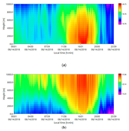
Figure 3.
Diurnal variations of (a) temperature and (b) potential temperature in degrees Celsius on 14 August 2018.
The same is true for the entire experiment. As the obtained temperature data demonstrate, in the atmosphere at the measurement site, the stable stratification occurred during 6–23 August 2018. This is seen in Figure 4, which shows the diurnal course of the average (over all of the measurement days) vertical temperature gradient. The values of the averaged vertical temperature gradient exceeded = 0.0098 deg/m during the entire 24 h. Correspondingly, the averaged vertical gradient of the potential temperature always had positive values.
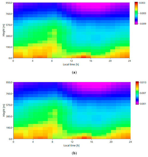
Figure 4.
Diurnal variations of the vertical gradients of (a) temperature and (b) potential temperature averaged for the period of measurements on 6–23 August 2018.
Low-level jets with a horizontal velocity of 10 m/s and up were observed nearly every day on 6–23 August in the boundary layer over the measurement site. Figure 5 shows the spatiotemporal distributions of the wind velocity and the Richardson number obtained from data of the wind lidar and temperature profiler for 9, 11, 12, 18, 19 and 21–23 August 2018. In these days, the horizontal wind velocity was strong at heights of 100 to 500 m, exceeding at the center of this layer a speed of 10 m/s during 12 h and more. On 21–22 August, the jet stream existed for more than 36 h. In some periods, such as the night of 22–23 August and 23 August, two jet streams with significantly different directions of wind flows were observed simultaneously at different heights. The distributions shown in Figure 5 were drawn with a 12 min averaging of the estimated parameters. Areas with unrealistic data on wind velocity and with corresponding data on the Richardson number obtained under conditions of fog or low cloudiness on 9 and 19 August are shown by grey color.
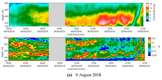
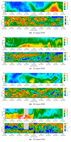
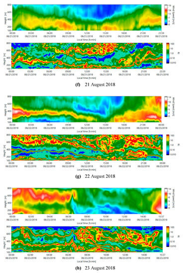
Figure 5.
Spatiotemporal distributions of the wind velocity and Richardson number on (a) 9, (b) 11, (c) 12, (d) 18, (e) 19, and (f–h) 21–23 August 2018.
It is seen from the data shown in Figure 5 that the distributions of the Richardson number are variable in time and have the layered structure in height. There are layers where the Richardson number exceeds Ricr = 0.25. Layers with large Richardson numbers alternate between layers where Ri < Ricr. All of the jets observed are characterized by a very thin (only a few tens of meters in height) layer formed at the center, at the jet axis, in which the Richardson number has very large positive values far exceeding the critical value of Ricr = 0.25. Except for the axial zone, the Richardson number in the jet area is much lower and may take values smaller than Ricr. That is, in the jet area, the thermal stability of the boundary layer decreased and channeled with the regime close to the neutral stratification appear.
Figure 6 shows several cross sections of the spatiotemporal distributions of the velocity for 19 and 21 August 2018. The cross sections are bound by isolines of a given minimal velocity. The grey color shows the areas where the speed of the wind was less than these given minimal velocities. The figure also demonstrates the spatiotemporal distributions of the Richardson number corresponding to these cross sections. Figure 6 visualizes the process of forming the channels with a small Richardson number around the jet axis where the Richardson number is large.
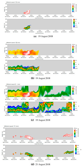
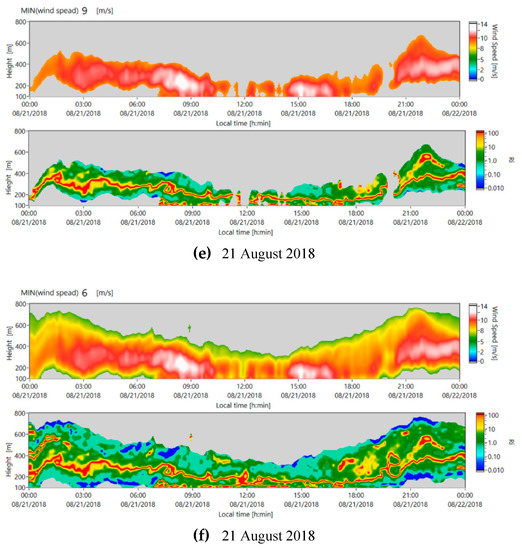
Figure 6.
Spatiotemporal distributions of the wind velocity and the Richardson number bounded by isolines of a given minimal velocity of (a) 15, (b) 10, and (c) 5 m/s for measurements on 19 August and (d) 11, (e) 9, and (f) 6 m/s for measurements on 21 August 2018.
3.2. Atmospheric Wind Waves and Wind Turbulence
Simultaneously with LLJs, in a stable boundary layer, internal atmospheric waves may arise. From all of the data obtained during the experiment on 6–23 August 2018, we revealed 14 cases of formations of internal waves. Propagating atmospheric waves manifest themselves through oscillations of wind velocity vector components. Thus, at first, we visually determined the height and the time of the appearance of periodic variations in the wind velocity components from the obtained distributions , , and . Then, the parameters of the atmospheric waves were determined by the method described in the literature [35]. As was found in the literature [35], the oscillating part of the wind velocity components was approximated by a harmonic wave with some period, amplitude, and phase. The period of oscillations for all the three components of the wind velocity vector was the same, the wave phase for the horizontal components differed from phase for the vertical component of the wind by , while the amplitude of oscillations for the longitudinal wind component was approximately three times larger than that for the vertical component.
In all of the cases of observation of atmospheric waves over the measurement site on 6–23 August 2018, the amplitude of the wave part of the horizontal wind velocity was no smaller than 0.6 m/s. The amplitudes of the oscillations of the vertical velocity were no smaller than 0.2 m/s. The amplitudes of the wind velocity oscillations were maximal in the waves observed from 02:30 to 03:30 local time (LT) on 23 August 2018 and amounted to 3 m/s for the horizontal wind velocity component and 1 m/s for the vertical component. The duration of observed atmospheric waves varied from 40 min to 5 h. The oscillation period ranged from 5 to 20 min. These oscillation periods far exceed the Brunt–Väisälä frequency (Equation (3)) calculated from the data of the temperature profiler. This means that the mountain terrain of the Baikal coastal zone exerted a prevailing impact on the formation of the internal waves observed in the experiment.
Along with the wave characteristics, we assessed the parameters of wind velocity turbulence during the existence of LLJs and internal atmospheric waves in the boundary layer. For this purpose, we selected lidar data obtained at a high signal to noise ratio SNR. Otherwise, as shown in the literature [22], the error of estimation of the turbulent energy dissipation rate may be unacceptably large, even if the probability of bad (false) estimate of the radial velocity is zero. To satisfy this requirement, we used the data obtained on 21–23 August 2018. In that period, the aerosol concentration over the measurement site provided a signal-to-noise ratio sufficient to estimate the turbulence parameters up to a height of 500 m with acceptable accuracy. Every estimate of the turbulence parameters was obtained as a result of averaging the lidar data measured during = 15 scans (measurement duration = 9 min).
Figure 7 shows the spatiotemporal distributions of the horizontal wind velocity , the turbulent energy dissipation rate , the variance of fluctuations of the radial velocity , and the integral scale of turbulence , as obtained from the lidar measurements on 01:00 to 07:00 LT on 21–22 August 2018, when the LLJs were observed in the atmosphere. The effective thickness of the jet stream, in height, on 21 August was approximately two to three times larger than the characteristic vertical size of the LLJ formed the next day. In each two-dimensional distribution in the figure, the black curves show the temporal profiles of the maximal wind velocity in the jet stream. Except for the spatiotemporal zone from 01:00 to 04:00 LT in the layer of 100–200 m, and in some small areas with extremely weak turbulence, the accuracy of estimation of the turbulence parameters in Figure 7 is quite acceptable. For the calculation of the relative errors, , , and , we used Equations (6)–(11) given in the literature [22], and Equations (1) and (2). The relative error of estimation was approximately 10% for the dissipation rate, ~13% for the variance of the radial velocity, and ~17% for the integral scale.
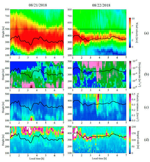
Figure 7.
Height–temporal distributions of wind velocity (a), turbulent energy dissipation rate (b), variance of radial velocity (c), and integral scale of turbulence (d) assessed from the lidar data obtained during low-level jets (LLJs) on 21 (left) and 22 (right) August 2018. Black curves show the smoothed time series of the maximal wind velocity (LLJ center).
Figure 8 and Figure 9 represent the time series and the height profiles of the wind velocity and the wind turbulence parameters obtained from the 2D distributions depicted in Figure 7. In Figure 9, we show 95% confidence intervals calculated for the turbulence parameters based on the assessed relative errors of , , and . According to Figure 7, Figure 8 and Figure 9, the turbulent energy dissipation rate at the central part of jet stream on 21 August 2018 did not exceed 0.0001 m2/s3, while the variance of the radial velocity varied from 0.002 to 0.05 m2/s2. The turbulence at the LLJ center was weak the next day from 01:00 to 03:00 as well. Then, the turbulence increased sharply at the central and the top parts of the jet stream. This intensification of turbulence occurred against the background of the oscillations of the wind velocity, with an amplitude of about 1 m/s at a height of 500 m observed from 03:00 to 04:15 LT (green curve in Figure 8a for 22 August 2018). The period of oscillations was 12 min (five wave trains for an hour). These oscillations were caused by the atmospheric internal wave. It is possible that the turbulence intensification was initiated by the breaking of that wave and the partial transformation of the wave energy into a turbulent one. In the data processing, the space–time high-frequency filtering of the radial velocity fluctuations measured by the lidar was used [16]. Thus, the presence of low-frequency quasi-harmonic oscillations caused by the atmospheric wave should not influence the accuracy of the estimation of the wind turbulence parameters.
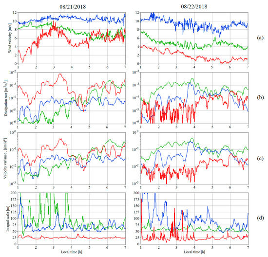
Figure 8.
Time series of wind velocity (a), turbulent energy dissipation rate (b), variance of the radial velocity (c), and integral scale of turbulence (d) at heights of 117 (red curves), 351 (blue curves), and 507 m (green curves) during LLJs of 21 (left) and 22 (right) August 2018. The data are taken from Figure 7.
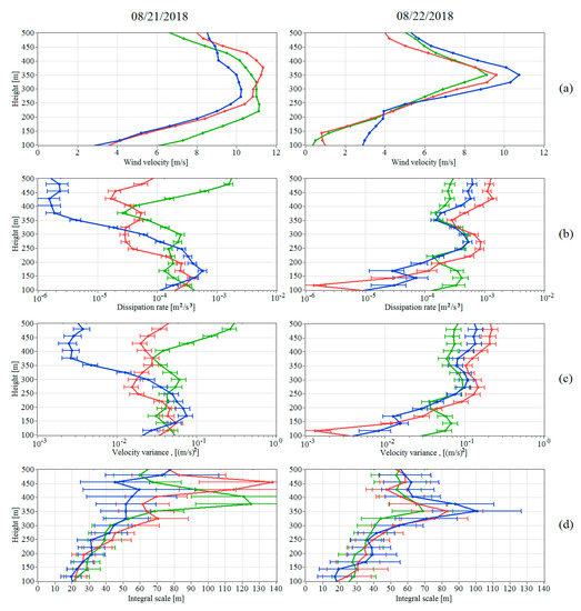
Figure 9.
Vertical profiles of wind velocity (a), turbulent energy dissipation rate (b), variance of the radial velocity (c), and integral scale of turbulence (d) at 02:00 (blue curves), 04:00 (red curves), and 06:00 LT (local time; green curves) during LLJs on 21 (left) and 22 (right) August 2018. The data are taken from Figure 7.
It follows from Figure 7d, Figure 8d, and Figure 9d that the integral scale of turbulence, on average, increased with height, achieving maximal values of 100–140 m at the central part of the jet streams and then decreasing down to 80 m (measurements of 21 August 2018) and to 60 m (measurements of 22 August 2018) at a height of 500 m. The obtained estimates of the integral scale of turbulence agree with the experimental data [17,27].
The internal atmospheric wave with the highest amplitude was observed on the last day of the experiment on 23 August 2018. Figure 10 shows the height–temporal distributions of the wind velocity components , , and ; wind turbulence parameters , , and ; temperature ; and Richardson number obtained from the measurements on this day.
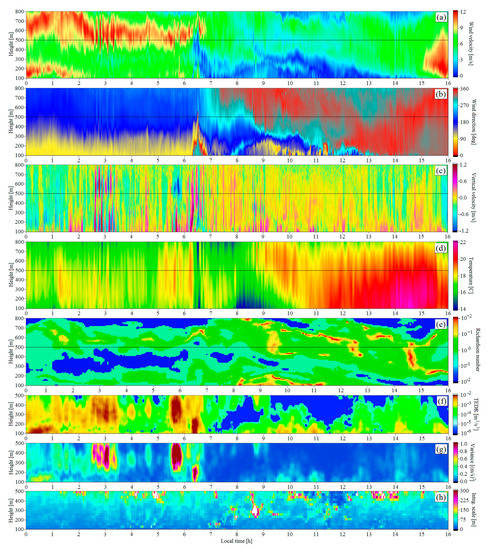
Figure 10.
Height–temporal distributions of wind velocity (a), wind direction angle (b), vertical component of wind velocity (c), air temperature (d), Richardson number (e), turbulent energy dissipation rate (f), variance of radial velocity (g), and integral scale of turbulence (h), as obtained from the data of the measurements by the lidar and by the profiler on 23 August 2018.
In contrast to the data on the horizontal wind velocity shown in Figure 5 and Figure 6, the 12 min averaging of the estimates of the wind parameters in Figure 10a–c was not performed. Data in Figure 10e were obtained as a result of 30 min averaging of estimates of the temperature and the wind velocity. According to Figure 5 and Figure 10a,b, two LLJs were observed simultaneously until approximately 06:00. One was at heights of 100–300 m, while another was at heights of 400–800 m. The angle between the directions of wind in these jet streams was about 90°. From Figure 10a–c, it can be seen that, in the periods of 02:30 to 03:30, 05:30 to 06:30, and 08:30 to 09:30 LT, the variations of the wind parameters in time had an oscillating character. Arguably, the internal atmospheric waves were generated in these periods over the measurement site. The oscillations in the period of 02:30 to 03:30 LT are the most clearly seen. To characterize the atmospheric wave that occurred in this period, we plotted the temporal profiles of the considered parameters at different heights for the time gap of 00:00 to 06:00 LT, when the two jet streams were observed simultaneously. Figure 11 represents the time series , , , , , , , and at heights of location of the lower (91 m) and the upper (506 m) jet streams as well as at a height of 325 m. The Brunt–Väisälä frequency was calculated for comparison with the oscillation period of the observed wave. The altitude profiles of these parameters in different moments of the time from gap 00:00 to 06:00 LT are plotted as well. Figure 12 shows these profiles for the moments of 01:00, 02:00, 03:00, 04:00, and 05:00 LT on 23 August 2018. In this figure, we show the 95% confidence intervals calculated for the turbulence parameters based on the assessed relative errors , , and .
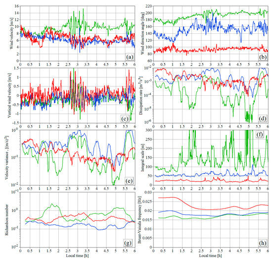
Figure 11.
Time series of wind velocity (a), wind direction angle (b), vertical component of the wind vector (c), turbulent energy dissipation rate (d), variance of the radial velocity (e), integral scale of turbulence (f), Richardson number (g), and Brunt–Väisälä frequency (h) at heights of 91 (red curves), 325 (blue curves), and 506 m (green curves). The data for (a–g) are taken from Figure 10.
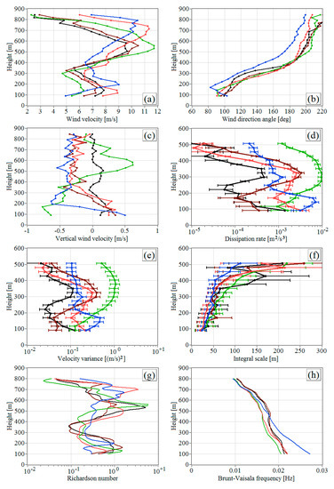
Figure 12.
Vertical profiles of wind velocity (a), wind direction angle (b), vertical component of the wind vector (c), turbulent energy dissipation rate (d), variance of the radial velocity (e), integral scale of turbulence (f), Richardson number (g), and Brunt–Väisälä frequency (h) at 01:00 (blue curves), 02:00 (red curves), 03:00 (green curves), 04:00 (brown curves), and 05:00 LT (black curves). The data for (a–g) are taken from Figure 10.
In Figure 11a–c, one can clearly see the oscillations of the wind parameters in the period of 02:30 to 03:30 LT. The amplitude of the oscillations of the horizontal wind velocity achieved 3 m/s at a height of 506 m, and the amplitude of oscillations of a vertical velocity was 1 m/s at all three heights under consideration.
From Figure 5 and Figure 10, it can clearly be seen that, at the heights of the jet streams, the Richardson number took values both larger and smaller than Ricr. As can be seen from Figure 10, Figure 11 and Figure 12, the wind turbulence was rather strong, especially during the atmospheric waves at heights where Ri < Ricr. According to Figure 10f,g, Figure 11d,e, and Figure 12d,e, during the atmospheric waves in the periods of 02:30 to 03:30, 05:30 to 06:30, and 08:30 to 09:30 LT, the strength of the wind turbulence was maximal at heights of 200–500 m, where the Richardson number was less Ricr (Figure 10e). At these heights, the dissipation rate of turbulence and the variance of wind velocity fluctuations exceeded their values at the lower heights where Ri > Ricr. As the internal waves disappeared, the turbulence strength became lower at all heights. The integral scale of turbulence in the presence of the jet streams and the atmospheric waves increased with height, on average, from 25 m at a height of 91 m to 120 m at a height of 500 m.
The analysis based on Equations (6)–(11) given in the literature [22], and Equations (1) and (2) showed that the presence of an atmospheric wave exerts no significant influence on the accuracy of the lidar estimates of and . For the lidar estimates of the wind turbulence parameters shown in Figure 10, Figure 11 and Figure 12, the relative error is 8%–14% for the dissipation rate , approximately 11% for the velocity variance , and 15%–27% for the integral scale of turbulence .
From the data of Figure 11h and Figure 12h, we can see that the Brunt–Väisälä frequency varied from 0.01 to 0.03 Hz. This means that the maximal period of oscillations corresponding to the Brunt–Väisälä frequency was 100 s. As the wind velocity vector was estimated from the lidar data obtained with the time resolution = 36 s, the oscillations with the period 1 min (if they were present in the atmosphere for the wind) could not be revealed from the lidar measurements. With the method proposed in [35], we found that the oscillation period of the wave observed since 02:30 to 03:30 LT on 23 August 2018 was = 8 min. Correspondingly, the frequency of the oscillations, = 0.00208 Hz, was an order of magnitude less than the Brunt–Väisälä frequency. Thus, most probably, the observed wave was generated as a consequence of the air flowing around the mountain terrain in the Baikal coastal zone (Figure 1).
In Figure 10a–c and Figure 11a–c, it can clearly be seen that the quasi-harmonic oscillations of the wind velocity vector components in the period of 02:30 to 03:30 LT were observed at all heights from 91 to 844 m relative to the height of the lidar location. Because of the Solar Telescope building and the surrounding landscape (Figure 1, right), we could not scan using a laser beam under an elevation angle of less 60° or measure the wind velocity lower 90 m relative to the lidar height. Therefore, for the analysis of the wind oscillations at low heights, we used the data of AMK-03 sonic anemometer (Sibanalitpribor, Tomsk, Russia) installed at a 10 m mast just near the Baikal coast line. The distance between the lidar and the sonic anemometer was about 1 km, and the difference between the height of measurement of the meteorological parameters by the anemometer and the lowest measurement height of the lidar was 261 m.
The lidar space–time low-frequency filtering of the measuring data [16] led to the averaging of the small-scale turbulent fluctuations of the measured velocity and simplified the detection of the atmospheric waves and the determination of the wave parameters , , and . The sonic anemometer measured air temperature , vertical , longitudinal (south–north), and (west–east) components of the wind velocity vector, with a very high sampling frequency of = 80 Hz (sampling interval = 0.0125 s), and did not average the small scale fluctuations. To diminish these small-scale (fast) turbulent fluctuations, we averaged the sonic anemometer data over 30 s, which is comparable to the sampling interval of the wind velocity measurements by the lidar = 36 s.
Figure 13 depicts the time series of the air temperature and the components of the wind velocity vector measured by the sonic anemometer after a 30 s averaging of the measurement data. As in Figure 10a,c and Figure 11a,c, in Figure 13, the quasi-harmonic oscillations are clearly seen within the time of 02:30 to 03:30 LT. These oscillations are the most pronounced for the horizontal south–north component of the wind. Using the data for this component in the interval of 02:30–03:30 LT, we determined the period of oscillations, , which appeared to be just the same as the estimate = 8 min at a height of 271–1024 m above the Baikal level obtained from the lidar data.
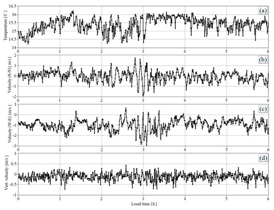
Figure 13.
Time series of air temperature (a), horizontal component of the wind velocity from south to north (b), horizontal component of the wind velocity from west to east (c), and vertical wind velocity (d) obtained from the measurements by the sonic anemometer at a height of 10 m above the Baikal level on 23 August 2018 after the application of the procedure of low-frequency filtering with 30 s averaging.
To demonstrate that = , we determined the frequencies (periods) of the internal atmospheric wave based on the wind velocity power spectra calculated with the fast Fourier transform from the time series of the wind velocity components measured by the sonic anemometer and by the lidar. In the Fourier transformations, we used 1 h intervals of the experimental time series, starting from 02:30 LT, with the addition of the corresponding number of zeros to the data array. Then, we determined the amplitude and the phase of the atmospheric wave through the approximation of the experimental time series by the harmonic functions with found periods using the least-square technique. The obtained model harmonic time dependences of the wind components are shown as red curves in Figure 14. The time series of the oscillating wind velocity components and their power spectra obtained from the sonic anemometer and the lidar measurements are shown in this figure as well. It is seen that the power spectra had a maximum at one, and the same frequency corresponded to the period of 8 min. A possible reason for the small deviations of the experimental time series from the model harmonic functions is the influence of large-scale wind velocity inhomogeneities, comparable with the diameter of the base of the cone of the scan in the case of the lidar measurements or with the distance at which the air masses were transported by the mean wind for 30 s, as in the case of the measurement by the sonic anemometer.
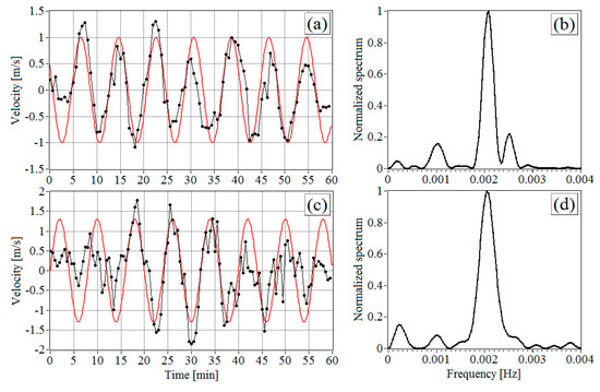
Figure 14.
Time series (a,c) of the oscillating components of the vertical wind velocity at a height of 271 m above the Baikal level (a) and the horizontal wind component at a height of 10 m above the Baikal level (c) starting from 02:30 LT on 23 August 2018 and their normalized power spectra (b,d). Circles connected by lines are the oscillating wind components obtained from the data of the lidar (a,b) and the sonic anemometer (c,d). Red curves are the results of the fitting of the harmonic dependence to the corresponding measured time dependence of the velocity.
From Figure 13a, it can be seen that, in the period of 02:30 to 03:30 LT, not only the wind components but also the temperature measured by the sonic anemometer experienced quasi-harmonic oscillations with an amplitude of about 0.75 °C. The period of these oscillations was close to the period of the wave variations of the wind velocity components = 8 min (Figure 13b,c).
Figure 15 depicts the time series of the air temperature obtained from the measurements by the microwave profiler on 23 August 2018 at different heights at the Lake Baikal coast. The profiler measured the temperature with a period of 3 min, and this time resolution was insufficient for revealing the oscillations with the period of an 8 min characteristic for temperature and wind quasi-harmonic variations shown in Figure 13. Therefore, to plot the time series of the temperature in Figure 15, the spline-interpolation of the profiler data, shown in Figure 10d, with a step of 1 min was carried out. The heights in Figure 15 were chosen with allowance for the location of the jet stream observed at that time, namely: 600 m at the LLJs center, 450 m at the bottom boundary of the jet, and 750 m at the top boundary.
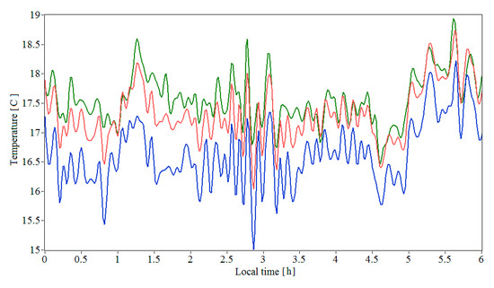
Figure 15.
Time series of the air temperature at heights of 450 (green curve), 600 (red curve), and 750 m (blue curve), as obtained from the measurements by the temperature profiler on 23 August 2018.
It is seen from the figure that, from 02:30 to 03:30 LT, quasi-harmonic oscillations of temperature with amplitude of about 1 Celsium degree were observed at the LLJ heights, as at the height of 10 m at the Baikal coast line (Figure 13a). The period of temperature oscillations in the LLJs zone was approximately 8 min, the same as the period of oscillations of the wind velocity components and the temperature in Figure 13 and the wind velocity in Figure 10 and Figure 11. Outside the LLJ, we failed to reveal reliably harmonic oscillations of temperature in contrast to the wind (Figure 10a,c, Figure 11a,c, and Figure 14a) from the profiler data. The simultaneous appearance of temperature oscillations with wave oscillations of the wind velocity components is likely being observed for the first time and can be a subject of further investigations.
4. Discussion and Conclusions
This paper reported the results of experimental studies on the atmospheric boundary layer in the coastal zone of Lake Baikal, with a coherent Doppler wind lidar Stream Line (Halo Photonics, Brockamin, Worcester, United Kingdom) and a microwave temperature profiler MTP-5 (Atmospheric Technology, Dolgoprudnyi, Moscow, Russia). Two-dimensional height–time distributions of wind velocity components, temperature, and parameters characterizing temperature regime and wind turbulence were obtained. It was found that, in the atmospheric boundary layer at the measurement site, stable stratification with the formation of low-level jets occurred at the heights of the measurements during 6–23 August 2018, day and night. The data on the variations of the Richardson number in the stable boundary layer at the heights of the jet formations were obtained for the first time. A characteristic feature of jets is that a thin (in height) layer, in which the Richardson number takes very large positive values far exceeding the critical meaning Ricr = 0.25, is formed at the center at the stream axis, where the wind speed is maximal. Beyond this layer, the Richardson number in the jets is much lower and may take values of Ri < Ricr. That is, channels of decreased stability, where the conditions are close to neutral stratification, arise in the zone of jets.
Beyond the jets and in the periods of absence of LLJ, the stable atmospheric boundary layer has an inhomogeneous fine scale layered structure characterized by strong variations of the Richardson number. There are layers where the Richardson number exceeds Ricr. In these layers, we should expect deviation from the Kolmogorov power law for a spatial spectrum of turbulent inhomogeneities (e.g., [3,38]). Layers with large Richardson numbers alternate with layers where Ri < Ricr. In the layers with small Richardson numbers, the spatial spectrum of the turbulence obeys the Kolmogorov power law. Such an alternated structure of the stable boundary layer containing areas with Kolmogorov and non-Kolmogorov turbulences is consistent with the model of the turbulent spatial spectrum of the temperature proposed for the upper troposphere and the stratosphere, characterized by the stable conditions. In accordance with the results in the literature [59,60], the spatial spectrum of the temperature turbulence in a stably stratified atmosphere can be represented as the sum of an isotropic (Kolmogorov) component and an anisotropic (non-Kolmogorov) component, which are statistically independent. The results presented in the literature [61] show that the anisotropic turbulence begins to play a predominant role at heights above 4–5 km. At lower heights, the main role is played by the isotropic Kolmogorov component. This exactly explains why the method of the azimuth structure function [21] used by us for estimation of wind velocity turbulence parameters—and based on the Kolmogorov (Karman) model—give acceptable results for not only unstable or neutral but for stable atmospheric boundary layers as well [17].
In the atmospheric waves observed in the experiment site on 6–23 August 2018, the amplitude of the wave part of the horizontal wind velocity component was above 0.6 m/s. The amplitude of the oscillations of the vertical velocity was no smaller than 0.2 m/s. The maximal amplitudes of the wind velocity oscillations were 3 m/s for the horizontal wind velocity components and 1 m/s for the vertical one. The lifetime of the observed atmospheric waves varied from 40 min to 5 h. The period of oscillations varied from 5 to 20 min and far exceeded the Brunt–Väisälä frequency. It was found that the temperature oscillations may appear simultaneously with the wave variations of the wind velocity components and may have the same period.
The wind turbulence in the central part of the observed jets, where Ri > Ricr, was weak; the turbulent energy dissipation rate usually did not exceed 0.0001 m2/s3, and the variance of the radial velocity varied from 0.002 to 0.05 m2/s2. However, the strength of the wind velocity turbulence may have increased considerably to the periphery of jets at heights where Ri < Ricr. The turbulence intensified at the appearance of internal atmospheric waves; in this case, the dissipation rate may have exceeded 0.001 m2/s3. In the presence of jets and internal waves in the atmosphere, the integral scale of turbulence increased with height, on average, from 20 m at 91 m to 60–120 m at 500 m, achieving maximal values of 70–140 m at the central part of jets.
The obtained estimates of low-level jets, atmospheric waves, and wind velocity turbulence parameters revealed that the diapason and the spatial structure of variation of the Richardson number expand the experimental database about the stably stratified boundary layer of the atmosphere and may be useful for developing ABL mathematical models used for various practical applications (weather forecast, wind energy, air transport safety, diffusion of atmospheric impurities, etc.).
Author Contributions
conceptualization, V.A.B.; methodology, V.A.B. and I.N.S.; software, I.N.S. and A.V.F.; experiment, A.V.F.; validation, V.A.B., I.N.S., and A.V.F.; investigation, V.A.B. and I.N.S.; writing (original draft preparation), V.A.B. and I.N.S.; writing (review and editing), V.A.B.; visualization, I.N.S. and A.V.F.; supervision, V.A.B.; project administration, V.A.B.; funding acquisition, V.A.B. All authors have read and agreed to the published version of the manuscript.
Funding
The work was performed under the project of the Russian Science Foundation, 19-17-00170.
Acknowledgments
The authors are grateful to their colleagues E.V. Gordeev and V.V. Kuskov for their help in conducting the lidar experiment. The results were obtained using the Unique Research Facility Large Solar Vacuum Telescope http://ckp-rf.ru/usu/200615/.
Conflicts of Interest
The authors declare no conflict of interest. The funders had no role in the design of the study; in the collection, analyses, or interpretation of data; in the writing of the manuscript; or in the decision to publish the results.
References
- Golitsyn, G.S. Statistics and Dynamics of Natural Processes and Phenomena; KRASAND Publishers: Moscow, Russia, 2013; ISBN 978-5-396-00502-0. (In Russian) [Google Scholar]
- Golitsyn, G.S. Laws of random walks derived by A.N. Kolmogorov in 1934. Rus. Meteorol. Hydrol. 2018, 43, 135–142. [Google Scholar] [CrossRef]
- Zilitinkevich, S.S. Atmospheric turbulence and planetary boundary layers; FIZMATLIT Publishers: Moscow, Russia, 2013; ISBN 978-5-9221-1519-3. (In Russian) [Google Scholar]
- Grachev, A.A.; Andreas, E.L.; Fairall, C.W.; Guest, P.S.; Persson, P.O.G. The critical Richardson number and limits of applicability of local similarity theory in the stable boundary layer. Bound. Layer Meteorol. 2013, 147, 51–82. [Google Scholar] [CrossRef]
- Holtslag, A.; Svensson, G.; Baas, P.; Basu, S.; Beare, B.; Beljaars, A.C.M.; Bosveld, F.C.; Cuxart, J.; Lindvall, J.; Steeneveld, G.J.; et al. Stable atmospheric boundary layers and diurnal cycles: Challenges for weather and climate models. Bull. Am. Meteorol. Soc. 2013, 94, 1691–1706. [Google Scholar] [CrossRef]
- Liang, J.N.; Zhang, L.; Wang, Y.; Cao, X.J.; Zhang, Q.; Wang, H.B.; Zhang, B.D. Turbulence regimes and the validity of similarity theory in the stable boundary layer over complex terrain of the Loess Plateau, China. J. Geophys. Res. 2014, 119, 6009–6021. [Google Scholar] [CrossRef]
- Bonin, T.; Blumberg, W.; Klein, P.; Chilson, P. Thermodynamic and turbulence characteristics of the southern great plains nocturnal boundary layer under differing turbulent regimes. Bound. Layer Meteorol. 2015, 157, 401–420. [Google Scholar] [CrossRef]
- Optis, M.; Monahan, A.; Bosveld, F.C. Limitations and breakdown of Monin-Obukhov similarity theory for wind profile extrapolation under stable stratification. Wind Energy 2016, 19, 1053–1054. [Google Scholar] [CrossRef]
- Sun, J.; Mahrt, L.; Nappo, C.; Lenschow, D.H. Wind and temperature oscillations generated by wave–turbulence interactions in the stably stratified boundary layer. J. Atmos. Sci. 2015, 72, 1484–1503. [Google Scholar] [CrossRef]
- Sun, J.; Nappo, C.J.; Mahrt, L.; Belušic, D.; Grisogono, B.; Stauffer, D.R.; Pulido, M.; Staquet, C.; Jiang, Q.; Pouquet, A.; et al. Review of wave turbulence interactions in the stable atmospheric boundary layer. Rev. Geophys. 2015, 53, 956–993. [Google Scholar] [CrossRef]
- Hogan, R.J.; Grant, A.L.M.; Illingworth, A.J.; Pearson, G.N.; O’Connor, E.J. Vertical velocity variance and skewness in clear and cloud-topped boundary layers as revealed by Doppler lidar. Q. J. R. Meteorol. Soc. 2009, 135, 635–643. [Google Scholar] [CrossRef]
- Pichugina, Y.L.; Banta, R.M. Stable boundary layer depth from high-resolution measurements of the mean wind profile. J. Appl. Meteorol. Climatol. 2010, 49, 20–35. [Google Scholar] [CrossRef]
- Barlow, J.F.; Dunbar, T.M.; Nemitz, E.G.; Wood, C.R.; Gallagher, M.W.; Davies, F.; O’Connor, E.; Harrison, R.M. Boundary layer dynamics over London, UK, as observed using Doppler lidar during REPARTEE-II. Atmos. Chem. Phys. 2011, 11, 2111–2125. [Google Scholar] [CrossRef]
- Huang, M.; Gao, Z.; Miao, S.; Chen, F.; Lemone, M.A.; Li, J.; Hu, F.; Wang, L. Estimate of boundary-layer depth over Beijing, China, using Doppler lidar data during SURF-2015. Bound. Layer Meteorol. 2017, 162, 503–522. [Google Scholar] [CrossRef]
- Bonin, T.A.; Carroll, B.J.; Hardesty, R.M.; Brewer, W.A.; Hajny, K.; Salmon, O.E.; Shepson, P.B. Doppler lidar observation of the mixing height in Indianapolis using an automated composite fuzzy logic approach. J. Atmos. Ocean. Technol. 2018, 35, 915–935. [Google Scholar] [CrossRef]
- Banakh, V.A.; Smalikho, I.N. Coherent Doppler Wind Lidars in a Turbulent Atmosphere; Artech House Publishers: Norwood, MA, USA, 2013; ISBN-13: 978-1-60807-667-3. [Google Scholar]
- Banakh, V.A.; Smalikho, I.N. Lidar Studies of Wind Turbulence in the Stable Atmospheric Boundary Layer. Remote Sens. 2018, 10, 1219. [Google Scholar] [CrossRef]
- Sathe, A.; Mann, J. A review of turbulence measurements using ground-based wind lidars. Atmos. Meas. Tech. 2013, 6, 3147–3167. [Google Scholar] [CrossRef]
- Fuertes, F.C.; Iungo, G.V.; Porté-Agel, F. 3D turbulence measurements using three synchronous wind lidars: Validation against sonic anemometry. J. Atmos. Ocean. Technol. 2014, 31, 1549–1556. [Google Scholar] [CrossRef]
- Sathe, A.; Mann, J.; Vasiljevic, N.; Lea, G. A six-beam method to measure turbulence statistics using ground-based wind lidars. Atmos. Meas. Tech. 2015, 8, 729–740. [Google Scholar] [CrossRef]
- Smalikho, I.N.; Banakh, V.A. Measurements of wind turbulence parameters by a conically scanning coherent Doppler lidar in the atmospheric boundary layer. Atmos. Meas. Techn. 2017, 10, 4191–4208. [Google Scholar] [CrossRef]
- Banakh, V.A.; Smalikho, I.N.; Falits, A.V. Estimation of the turbulence energy dissipation rate in the atmospheric boundary layer from measurements of the radial wind velocity by micropulse coherent Doppler lidar. Opt. Express 2017, 25, 22679–22692. [Google Scholar] [CrossRef]
- Bonin, T.A.; Choukulkar, A.; Brewer, W.A.; Sandberg, S.P.; Weickmann, A.M.; Pichugina, Y.; Banta, R.M.; Oncley, S.P.; Wolfe, D.E. Evaluation of Turbulence Measurement Techniques from a Single Doppler Lidar. Atmos. Meas. Tech. Discuss. 2017, 10, 3021–3039. [Google Scholar] [CrossRef]
- Newman, J.F.; Clifton, A. An error reduction algorithm to improve lidar turbulence estimates for wind energy. Wind Energy Sci. 2017, 2, 77–95. [Google Scholar] [CrossRef]
- Bodini, N.; Lundquist, J.K.; Newsom, R.K. Estimation of turbulence dissipation rate and its variability from sonic anemometer and wind Doppler lidar during the XPIA field campaign. Atmos. Meas. Tech. 2018, 11, 4291–4308. [Google Scholar] [CrossRef]
- Smalikho, I.N.; Banakh, V.A.; Falits, A.V.; Rudi, Y.A. Determination of the turbulent energy dissipation rate from data measured by a “Stream Line” lidar in the atmospheric surface layer. Opt. Atmos. Okeana 2015, 28, 901–905. (In Russian) [Google Scholar] [CrossRef]
- Smalikho, I.N.; Banakh, V.A.; Falits, A.V. Lidar measurements of wind turbulence parameters in the atmospheric boundary layer. Opt. Atmos. Okeana 2017, 30, 342–349. (In Russian) [Google Scholar] [CrossRef]
- Kallistratova, M.A.; Kouznetsov, R.D. Low-level jets in the Moscow region in summer and winter observed with a sodar network. Bound. Layer Meteorol. 2012, 143, 159–175. [Google Scholar] [CrossRef]
- Kallistratova, M.A.; Kouznetsov, R.D.; Kramar, V.F.; Kuznetsov, D.D. Profiles of wind speed variances within nocturnal low-level jets observed with a sodar. J. Atmosp. Ocean. Technol. 2013, 30, 1970–1977. [Google Scholar] [CrossRef]
- Newsom, R.K.; Banta, R.M. Shear-flow instability in the stable nocturnal boundary layer as observed by Doppler lidar during CASES-99. J. Atmos. Sci. 2003, 60, 16–33. [Google Scholar] [CrossRef]
- Banta, R.M.; Newsom, R.K.; Lundquist, J.K.; Pichugina, Y.L.; Coulter, R.L.; Mahrt, L. Nocturnal low-level jet characteristics over Kansas during CASES-99. Bound. Layer Meteorol. 2002, 105, 221–252. [Google Scholar] [CrossRef]
- Banta, R.M.; Pichugina, Y.L.; Newsom, R.K. Relationship between low-level jet properties and turbulence kinetic energy in the nocturnal stable boundary layer. J. Atmos. Sci. 2003, 60, 2549–2555. [Google Scholar] [CrossRef]
- Banta, R.M.; Pichugina, Y.L.; Brewer, W.A. Turbulent velocity-variance profiles in the stable boundary layer generated by a nocturnal low-level jet. J. Atmos. Sci. 2006, 63, 2700–2719. [Google Scholar] [CrossRef]
- Lyulyukin, V.; Kouznetsov, R.; Kallistratova, M. The composite shape and structure of braid patterns in Kelvin-Helmholtz billows observed with a sodar. J. Atmos. Ocean. Technol. 2013, 30, 2704–2711. [Google Scholar] [CrossRef]
- Banakh, V.A.; Smalikho, I.N. Lidar observations of atmospheric internal waves in the boundary layer of atmosphere on the coast of Lake Baikal. Atmos. Meas. Tech. 2016, 9, 5239–5248. [Google Scholar] [CrossRef]
- Chouza, F.; Reitebuch, O.; Jähn, M.; Rahm, S.; Weinzierl, B. Vertical wind retrieved by airborne lidar and analysis of island induced gravity waves in combination with numerical models and in situ particle measurements. Atmos. Chem. Phys. 2016, 16, 4675–4692. [Google Scholar] [CrossRef]
- Kallistratova, M.A.; Petenko, I.V.; Kouznetsov, R.D.; Kulichkov, S.N.; Chkhetiani, O.G.; Chunchusov, I.P.; Lyulyukin, V.S.; Zaitseva, D.V.; Vazaeva, N.V.; Kuznetsov, D.D.; et al. Sodar sounding of the atmospheric boundary layer: Review of studies at the Obukhov Institute of Atmospheric Physics, Russian Academy of Sciences. Izv. Atmosp. Ocean. Phys. 2018, 54, 242–256. [Google Scholar] [CrossRef]
- Chunchuzov, I.P. Nonlinear formation of the three-dimensional spectrum of mesoscale wind velocity and temperature fluctuations in a stably stratified atmosphere. J. Atmos. Sci. 2018, 75, 3447–3467. [Google Scholar] [CrossRef]
- Long, R.R.; Morton, J.B. Solitary waves in compressible, stratified fluids. Tellus 1966, 18, 79–85. [Google Scholar] [CrossRef][Green Version]
- Baines, P.G. On internal tide generation models. Deep Sea Res. Part A Oceanogr. Res. Pap. 1982, 29, 307–338. [Google Scholar] [CrossRef]
- Baines, P.G. Internal Tides, Internal Waves and Near-Inertial Motions. In Baroclinic Processes on Continental Shelves; Mooers, C.N., Ed.; Blackwell Science, Inc.: Boston, MA, USA, 2013. [Google Scholar] [CrossRef]
- Fernando, H.J. Environmental Stratified Flows. Chapter 6: Turbulence in Stratified Fluids; Springer: Boston, MA, USA, 2003; pp. 161–189. [Google Scholar] [CrossRef]
- Emmanuel, C.B. Richardson number profiles through shear instability wave regions observed in the lower planetary boundary layer. Bound. Layer Meteorol. 1973, 5, 19–27. [Google Scholar] [CrossRef]
- Cheung, T.K. Sodar observations of the stable lower atmospheric boundary layer at barrow, Alaska. Bound. Layer Meteorol. 1991, 57, 251–274. [Google Scholar] [CrossRef]
- Petenko, I.; Argentini, S.; Casasanta, G.; Kallistratova, M.; Sozzi, R.; Viola, A. Wavelike Structures in the Turbulent Layer During the Morning Development of Convection at Dome C, Antarctica. Bound. Layer Meteorol. 2016, 161, 289–307. [Google Scholar] [CrossRef]
- Petenko, I.; Argentini, S.; Casasanta, G.; Genthon, C.; Kallistratova, M. Stable Surface-Based Turbulent Layer During the Polar Winter at Dome C, Antarctica: Sodar and In Situ Observations. Bound. Layer Meteorol. 2019, 171, 101–128. [Google Scholar] [CrossRef]
- Helmis, C.G.; Sgouros, G.; Tombrou, M.; Schäfer, K.; Münkel, C.; Bossioli, E.; Dandou, A. A Comparative Study and Evaluation of Mixing-Height Estimation Based on Sodar-RASS, Ceilometer Data and Numerical Model Simulations. Bound. Layer Meteorol. 2012, 145, 507–526. [Google Scholar] [CrossRef]
- Banakh, V.A.; Smalikho, I.N.; Falits, A.V.; Belan, B.D.; Arshinov, M.Y.; Antokhin, P.N. Joint radiosonde and Doppler lidar measurements of wind in the boundary layer of the atmosphere. Atmos. Ocean. Opt. 2015, 28, 185–191. [Google Scholar] [CrossRef]
- Smalikho, I.N.; Banakh, V.A. Accuracy of estimation of the turbulent energy dissipation rate from wind measurements with a conically scanning pulsed coherent Doppler lidar. Part I. Algorithm of data processing. Atmos. Ocean. Opt. 2013, 26, 404–410. [Google Scholar] [CrossRef]
- Lenschow, D.H.; Wulfmeyer, V.; Senff, C. Measuring second-through fourth-order moments in noisy data. J. Atmos. Ocean. Technol. 2000, 17, 1330–1347. [Google Scholar] [CrossRef]
- Kadygrov, E.N. Microwave radiometry of atmospheric boundary layer: Method, equipment, and applications. Opt. Atmos. Okeana 2009, 22, 697–704. (In Russian) [Google Scholar]
- Kadygrov, E.N.; Ganshin, E.V.; Miller, E.A.; Tochilkina, T.A. Ground based microwave temperature profilers: Potential and experimental data. Atmosph. Ocean. Optics 2015, 28, 598–605. [Google Scholar] [CrossRef]
- Miller, E.A.; Vorob’eva, E.A.; Kadygrov, E.N. Analysis of Seasonal and Annual Peculiarities of the Temperature Stratification of an Urban Heat Island. Atmosph. Ocean. Optics 2009, 22, 435–440. [Google Scholar] [CrossRef]
- Vorobyeva, E.A.; Shaposhnikov, A.N.; Folomeev, V.V.; Kadygrov, E.N. Results of atmospheric boundary layer thermal stratification measurements in Guamsky canyon. Opt. Atmos. Okeana 2010, 23, 505–509. (In Russian) [Google Scholar]
- Ezau, I.N.; Wolf, T.; Miller, E.A.; Repina, I.A.; Troitskaya, Y.I.; Zilitinkevich, S.S. The analysis of results of remote sensing monitoring of the temperature profile in lower atmosphere in Bergen (Norway). Rus. Meteorol. Hydrol. 2013, 38, 715–722. [Google Scholar] [CrossRef]
- Kadygrov, E.N.; Gorelik, A.G.; Miller, E.A.; Nekrasov, V.V.; Troitsky, A.V.; Tochilkina, T.A.; Shaposhnikov, A.N. Results of tropospheric thermodynamics monitoring on the base of multichannel microwave system data. Opt. Atmos. Okeana 2013, 26, 459–465. (In Russian) [Google Scholar]
- Gorchakov, G.I.; Kadygrov, E.N.; Kunitsyn, V.E.; Zakharov, V.I.; Semutnikova, E.G.; Karpov, A.V.; Kurbatov, G.A.; Miller, E.A.; Sitanskii, S.I. The Moscow Heat Island in the Blocking Anticyclone during Summer 2010. Dokl. Earth Sci. 2014, 456, 736–740. [Google Scholar] [CrossRef]
- Banakh, V.A.; Falits, A.V.; Sukharev, A.A.; Orozobakov, A.T. Variations of temperature regime of the atmospheric boundary layer in regions with various orography. In Proceedings of the SPIE 24th International Symposium on Atmospheric and Ocean Optics: Atmospheric Physics, Tomsk, Russia, 2–5 July 2018; Volume 10833, p. 108333. [Google Scholar] [CrossRef]
- Gurvich, A.S.; Brekhovskikh, V.L. Study of the Turbulence and Inner Waves in the Stratosphere Based on the Observations of Stellar Scintillations from Space: A Model of Scintillation Spectra. Waves Random Media 2001, 11, 163–181. [Google Scholar] [CrossRef]
- Gurvich, A.S.; Kan, V. Structure of air density irregularities in the stratosphere from spacecraft observations of stellar scintillation: 1. Three-dimensional spectrum model and recovery of its parameters. 2. Characteristic scales, structure characteristics, and kinetic energy dissipation. Izv. Atmos. Ocean. Phys. 2003, 39, 300–321. [Google Scholar]
- Kan, V.; Gorbunov, M.E.; Sofieva, V.F. Fluctuations of radio occultation signals in sounding the Earth’s atmosphere. Atmos. Meas. Tech. 2018, 11, 663–680. [Google Scholar] [CrossRef]
© 2020 by the authors. Licensee MDPI, Basel, Switzerland. This article is an open access article distributed under the terms and conditions of the Creative Commons Attribution (CC BY) license (http://creativecommons.org/licenses/by/4.0/).