Abstract
In yield analysis and plant design of concentrated solar power (CSP) tower plants, increased uncertainties are caused by the mostly unknown solar attenuation between the concentrating heliostat field and the receiver on top of the tower. This attenuation is caused mainly by aerosol particles and water vapor. Various on-site measurement methods of atmospheric extinction in solar tower plants have been developed during recent years, but during resource assessment for distinct tower plant projects in-situ measurement data sets are typically not available. To overcome this lack of information, a transmittance model (TM) has been previously developed and enhanced by the authors to derive the atmospheric transmittance between a heliostat and receiver on the basis of common direct normal irradiance (DNI), temperature, relative humidity and barometric pressure measurements. Previously the model was only tested at one site. In this manuscript, the enhanced TM is validated for three sites (CIEMAT’s Plataforma Solar de Almería (PSA), Spain, Missour, Morocco (MIS) and Zagora, Morocco (ZAG)). As the strongest assumption in the TM is the vertical aerosol particle profile, three different approaches to describe the vertical profile are tested in the TM. One approach assumes a homogeneous aerosol profile up to 1 kilometer above ground, the second approach is based on LIVAS profiles obtained from Lidar measurements and the third approach uses boundary layer height (BLH) data of the European Centre for Medium-Range Weather Forecasts (ECMWF). The derived broadband transmittance for a slant range of 1 km () time series is compared with a reference data set of on-site absorption- and broadband corrected derived from meteorological optical range (MOR) measurements for the temporal period between January 2015 and November 2017. The absolute mean bias error (MBE) for the TM’s using the three different aerosol profiles lies below 5% except for ZAG and one profile assumption. The MBE is close to 0 for PSA and MIS assuming a homogeneous extinction coefficient up to 1 km above ground. The root mean square error (RMSE) is around 5–6% for PSA and ZAG and around 7–8% for MIS. The TM performs better during summer months, during which more data points have been evaluated. This validation proves the applicability of the transmittance model for resource assessment at various sites. It enables the identification of a clear site with high with a high accuracy and provides an estimation of the for hazy sites. Thus it facilitates the decision if on-site extinction measurements are necessary. The model can be used to improve the accuracy of yield analysis of tower plants and allows the site adapted design.
1. Introduction
CSP (concentrated solar power) will play a strong role in the Middle East and North Africa region’s electricity market and especially in Morocco in the future ([1]). In concentrated solar tower plants, the radiation which is reflected by the heliostat field is partially lost on its way to the central receiver due to atmospheric extinction. This effect on the plant yield varies with the actual aerosol and water vapor load at a certain site and the plant yield can be reduced significantly, especially at arid sites. So far, on-site measurements are performed only rarely to take this effect into account during the project planning or plant optimization phase. It is still common to choose one of two cases representing clear or hazy conditions for yield calculations. Applying standard extinction conditions can lead to an under or overestimation of several percent of the expected annual plant yield dependent on the location and plant configuration ([2]). As such errors have to be expected for most current projects, banks and engineering, procurement and construction (EPC) contractors usually include additional risk margins in their yield calculations which unnecessarily increase the price of solar tower plants. To make CSP tower plants more cost-competitive and to ideally exploit their potential, these plants have to be optimally designed for the local conditions of the plant site. For example, the total heliostat surface combined with the available direct normal irradiance (DNI) and the extinction must fit to the receiver design, the storage and the power block. Therefore, the atmospheric extinction at the plant site has to be known and considered in the applied simulation models. However, the extinction conditions and their variability at different sites are widely unknown at the moment.
A review of modeling, experimental studies and measurement methods can be found in [3]. The most applied model equations to include atmospheric extinction which are implemented in different ray-tracing tools are summarized and compared in [3]. Additionally, several developed approaches to determine atmospheric extinction and different studies about the effect of atmospheric extinction on the tower plant yield are summarized and won’t be mentioned in this summary again.
Recently, more studies have been published on the topic of atmospheric extinction and its influence on solar tower plant performance.
To measure atmospheric extinction, following works have been published:
- An experimental methodology has been proposed by [4,5], based on the use of two high resolution cameras that take simultaneous images from a Lambertian target.
- A similar system is being investigated by [6] using reflector telescopes and a photo diode array spectrometer to measure the extinction in solar tower plants.
- In [7], a diffusometer is used to estimate atmospheric extinction levels at two different sites.
- Ref. [8] showed, based on monochromatic ceilometer measurements, that Sahara-dust outbreak events in South-East Spain can increase the monochromatic attenuation for slant ranges of 1 km up to 25%.
- Ref. [9] derives the atmospheric extinction from remote sensing data from MODIS and AERONET for Morocco.
To model radiation losses due to atmospheric extinction, the following approaches have been presented:
- Ref. [10] models the atmospheric extinction for different atmospheric conditions and site elevation with the MODTRAN radiative transfer code. The simulations showed that the solar irradiance can be reduced up to 30% under moderately turbid conditions.
- Radiation losses caused only by water vapor are analyzed by [11].
- This relationship is also investigated in [12] using artificial neural networks to express the non-linear relationship between atmospheric extinction and water vapor content in the atmosphere.
- Ref. [13] models the atmospheric extinction at CIEMAT’s Plataforma Solar de Almería (PSA) with the model of [14], generating a typical meteorological year (TMY) using five years of aerosol optical depth (AOD) measurements of the AERONET network.
A sensitivity analysis of the influence of temporal variation of atmospheric extinction has been conducted in [15,16] and showed a significant impact in the plant performance and in optical efficiency. Ref. [17] compared the vertical aerosol concentration within the lowest 300 m layer based on satellite data from CALIPSO and ECMWF-MACC data. The comparison is performed to evaluate the usage of these sources of aerosol data to improve the assessment of potential concentrated solar power (CSP) plants. Ref. [18] analyzed the inter annual variability of aerosol optical depth (AOD) and irradiance in Quarzazate (Morocco) and its influence on the characterization of extinction conditions for a certain site.
In this study, meteorological optical range (MOR) measurements, the according absorption and broadband correction (ABC) method [19] and the corrected broadband extinction and transmittance results at two desert sites (Missour (MIS) and Zagora (ZAG)) in Morocco (part of the enerMENA network, [20]) and the PSA in Spain will be evaluated. The data sets are compared to each other and seasonal and inter-annual variability is discussed.
The principle of the DNI measurement based transmittance model (TM) from [21] is described in Section 2. A validation of the TM with the help of ABC corrected measured transmittance data will be presented for all three sites in Section 3. The results of the validation and its discussion are presented In Section 4 and Section 5 the main conclusions about the validation are summarized.
2. Transmittance Model Based on DNI Measurements
The Beer–Lambert–Bouguer law describes the monocromatic extinction coefficient. For the relation between the broadband extinction coefficient and the and reflected by a heliostat which reaches the central receiver after traveling through an atmospheric layer between A and B, the following approximation can be used:
denotes the broadband transmittance for a slant range x. The term “broadband” refers to the wavelength range between 250 and 4000 nm in this work. The broadband transmittance can be expressed by or the broadband optical depth of the layer between A and B and the incident zenith angle of the irradiance.
In [22,23,24], an approach has been developed to derive the atmospheric transmittance in the lowest atmospheric layer above ground with the help of on-site DNI measurements. According to [22,23,24], the extinction coefficient can be approximated with the following formula:
where is the measured DNI at ground level and is the simulated DNI for an aerosol-free atmosphere at ground level. The coefficients a and b are derived using radiative transfer calculations with the radiative transfer code libRadtran ([25,26]).
The attenuation between the receiver and a heliostat could be estimated with this model, but the model has been developed only for one altitude and water vapor content in [22,23,24]. This approach has been further enhanced in [2,21] and the coefficients a and b and have been derived for several meteorological conditions.
To derive the TM for a distinct site of interest, a theoretical clear sky DNI for an atmosphere without any aerosol particles is simulated with radiative transfer calculations. These simulations are performed for various water vapor concentrations as well as different solar zenith angle (SZA). The DNI at ground level is highly dependent on the aerosol particles and water vapor concentrations and vertical distributions. Most aerosol particles and water vapor droplets are located in the lower troposphere. The TM is based on the assumption that the aerosol height profile is known. In [21,27], different height profiles have been tested for PSA. From on-site actual DNI measurements, the extinction coefficient close to the ground can then be derived. The TM has to be derived for each site individually. To do so, an approximation of the site-dependent aerosol extinction height profile is necessary as explained in detail in [21].
The enhanced TM is able to derive the transmittance for a slant range of 1 km () from DNI as well as common meteorological measurements like ambient temperature, barometric pressure and relative humidity.
The absolute uncertainty of the transmittance which has been derived with the TM is increasing for decreasing transmittances. An uncertainty between 0.033 and 0.04 for equal to 0.9 have been derived for a data set with 1 minute temporal resolution For the site of PSA ([2]).
3. Transmittance Model Validation
In this study, the TM has been applied and validated at three different sites in Morocco and Spain: CIEMAT’s PSA (Spain) and IRESEN’s stations in MIS (Morocco) and ZAG (Morocco). The site locations are shown in Figure 1 and the information about the sites is summarized in Table 1.
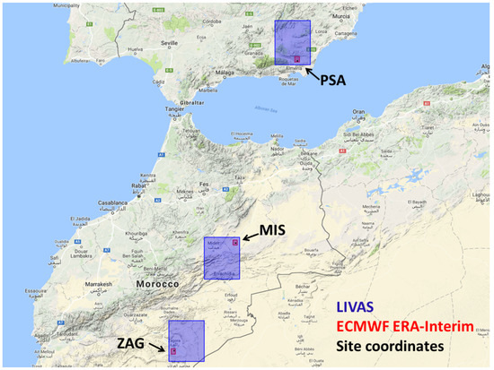
Figure 1.
Location of PSA, MIS and ZAG as well as ECMWF BLH and LIVAS extinction profile grid.

Table 1.
LibRadtran input for TM development.
Three aerosol height profiles and the performance of the corresponding TM have been tested for each site as explained in the following subsection. The applied standard aerosol types within the libRadtran simulations for the TM development for each aerosol height profile are listed in Table 1.
3.1. Aerosol Height Profiles
The following height profiles will be used in this validation approach for PSA, MIS and ZAG:
- An extinction profile with a constant aerosol extinction coefficient up to 1 km above the ground and no extinction above 1 km (“TM-H1000”)
- The extinction height profile for each validation site of the LIVAS climatology of [28] (description of modification of LIVAS profile can be found in Section 4.1.1 (“TM-LIVAS”).
- The constant extinction profile as in TM-H1000 of [21] is scaled accordingly to the BLH instead of 1 km. The BLH has been extracted from the ERA-Interim reanalysis data set of ECMWF ([29]). It is assumed that the total amount of aerosol particles is homogeneously distributed in the lowest layer above ground up to the site- and time-dependent BLH (“TM-BLH”).
Figure 1 indicates the grid sizes of LIVAS as well as the ECMWF BLH grid points of all sites.
In this context, the different data sources have been inter-compared (see Section 4.1.1, Section 4.1.2 and Section 4.1.3): The LIVAS climatology ([28]), the BLH data from ECMWF ([29]) and measurements of the lowest aerosol layer (LAL) from an on-site mounted ceilometer at PSA ([30]).
3.2. Reference Data Set
As a reference data set ABC corrected MOR measurements are used for the three sites. The MOR is a parameter to measure the optical clearness of the atmosphere and can be measured with commercially available instruments.
The MOR is defined as the length of the path in the atmosphere which is required to reduce the luminous flux in a collimated beam from an incandescent lamp, at a color temperature of 2700 K, to 5% of its original value ([31,32]).
With the help of the Koschmieder approximation [31] the between heliostat and receiver can be approximated from the parameter MOR:
where is the monochromatic extinction coefficient at 550 nm, x is the slant range (distance between heliostat and receiver) and is the monochromatic transmittance at 550 nm for a slant range x. The spectral variation of the extinction coefficient is neglected by the Koschmieder approximation.
The sensor used in this analysis to measure the MOR at the evaluated sites is the FS11 scatterometer of Vaisala ([19,33]). It emits a defined radiation signal and measures the light that is scattered towards a given angular region. Based on assumptions for the angular distribution of the scattered light and the atmospheric absorption, the MOR is derived by an internal algorithm of the FS11.
The raw MOR measurements of the FS11 have to be corrected for the varying solar spectrum as well as for the absorption contribution to atmospheric extinction. A method for this correction has been developed in [19].
A spectral correction has to be performed as the FS11 (as most MOR measurement instruments) does not cover the whole solar spectrum which is important for concentrated solar power (CSP). Because the measurements are performed in a narrow wavelength range around 875 nm in the infrared region which is usually not representative for the actual DNI spectrum, the correction is necessary and its effect varies with location and time. The correction due to atmospheric absorption has to be performed for this scatterometer because the FS11 only measures the scatter contribution to extinction. The absorption effect is covered to a certain extent by the instrument but extremely absorbing phenomena are not included in the internal algorithm of the FS11 ([2]).
The ABC method to correct MOR data, which is described in detail in [19], is based on calculations with the radiative transfer tool libRadtran ([25,26]). The spectral correction factor is calculated by simulating the time-dependent solar spectrum and deriving the ratio between the broadband atmospheric transmittance and the monochromatic atmospheric transmittance at the wavelength of the FS11. The time-dependent absorption correction is derived by simulating the transmittance with and without considering atmospheric absorption. The absorption correction factor is then the ratio between these two simulated transmittances for each time step and the mean ratio of these transmittances as the absorption effect is to a certain extent already covered by the internal algorithm of the FS11.
The ABC method has been applied on the recorded MOR data sets for three sites. FS11 scatterometers of Vaisala have been mounted at CIEMAT’s PSA as well as at IRESEN’s stations in MIS and ZAG for several years. The period between February 2015 and November 2017 has been evaluated in this work.
Within the radiative transfer calculations with libRadtran, the mid-latitude summer standard atmosphere “afglms” ([34]) has been used for all three sites. For PSA the spectral AOD, the Ångström parameter as well as the ozone and water vapor column concentration are available from the co-located AERONET station ([35]). This information has been used in the ABC method (see also [19]). For MIS and ZAG standard aerosol types and distributions have been assumed due to the lack of AERONET data. The assumed standard aerosol types for the libRadtran simulations, which have been used to derive the ABC factors, are obtained from the software package OPAC (optical properties of aerosols and clouds, see [36]). For MIS the standard continental clean aerosol was chosen as the site is in a remote continental area with low anthropogenic influences. Continental average standard aerosol has been selected for ZAG.
The uncertainty of the reference data set has been approximated by applying the Gauss error propagation ([2]). The absolute uncertainty is estimated to lie between 0.04 and 0.08 for dependent on for a data set with a temporal resolution of 1 minute. The absolute uncertainty is increasing for decreasing and lies at around 0.043 for equal to 0.9. For yearly averages, it can be assumed that the absolute uncertainty of equal to 0.9 lies at around 0.02 ([2]).
4. Results and Discussion of Transmittance Model Validation
4.1. Discussion of Extinction Height Profiles
The intention of testing different data sources for the extinction profile is to test which source or parameter might be the best approximation for the specific site to be used within the TM. The LIVAS profiles from the three sites are compared to detect possibly different structures in the extinction profiles (see Section 4.1.1). The BLH of ECMWF ([29,37,38]) is analyzed to evaluate if this parameter can be used to approximate the height until which the extinction coefficient is homogeneous and no aerosol particles can be found above this height. To investigate if the BLH diurnal and annual course represents the on-site conditions, the BLH is inter-compared to LAL measurement of an on-site ceilometer in Section 4.1.2. In Section 4.1.3 the average LAL and BLH at PSA are inter-compared with the corresponding LIVAS profile.
4.1.1. Comparison of Average LIVAS Extinction Profiles for PSA, MIS and ZAG
Figure 2 shows the available extinction profiles for 532 nm for PSA, MIS and ZAG. The dotted lines show the original extinction profile as provided by the LIVAS climatology ([28]) for the closest grid point for all three sites. It is assumed that the lowest peak of the extinction coefficient at each site is caused by systematic errors e.g., overlap problems. Therefore, we kept the extinction coefficient constant at the level of 876 m for PSA (1235 m and 996 m for MIS and ZAG, respectively) for the layer underneath until ground level (see also [21]). These modified profiles are shown with the solid curves in Figure 2 and are used in this analysis, indicated by “LIVAS”. It can be seen that the LIVAS profiles of PSA and MIS show a similar shape with maximal extinction coefficients close to the ground. In ZAG a second maximum can be observed in about 3.5 km height above ground.
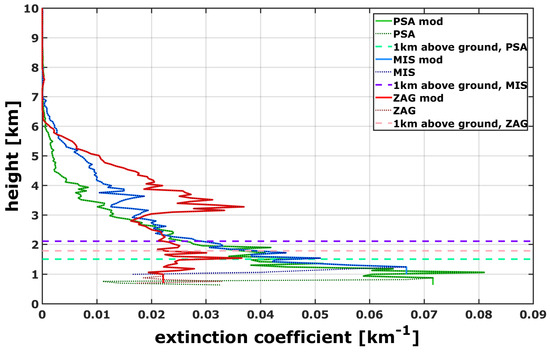
Figure 2.
LIVAS extinction profiles at 532 nm for PSA, MIS and ZAG.
4.1.2. Analysis of Diurnal and Annual Course of BLH from ECMWF and Ceilometer Aerosol Layer Measurements at PSA
A CHM15k ceilometer of Lufft ([30]) is mounted at PSA since May 2013 and continuously measures the backscattered signal up to a height of 15 km above ground with a temporal resolution of 15 s. The measurements from 1 January 2014 until 31 December 2016 have been used for this analysis. The internal software of the ceilometer automatically detects the LAL within the planetary boundary layer. The aerosol layers are identified by a pre-defined gradient in the backscatter signal (see [30]).
The BLH data of the ECMWF ERA-Interim reanalysis data set has been extracted for the three sites PSA, MIS and ZAG. The BLH data is available in a three hour temporal resolution (0, 3, 6, 9, 12, 15, 18, 21 h) and is defined with the potential temperature and the Bulk Richardson number according to [39] following the conclusions of [40]. It is the depth of air next to the Earth’s surface which is most affected by the resistance to the transfer of momentum, heat or moisture across the surface [37].
The BLH typically drops to lower heights above ground during cooling at night and rises to several kilometers over desert regions on hot sunny days ([37]). Averaged values between 1999 and 2016 have been computed for this analysis. The data points have been linearly interpolated to one minute temporal resolution. Data points for solar elevation angles less than 5° have been ignored.
Although the parameters LAL and BLH are defined in different ways and therefore cannot be directly compared, this inter-comparison intends to analyze if both parameters show a similar diurnal and annual course at PSA. Also, both parameters might be useful for the TM.
Figure 3 displays the mean diurnal course of the automatically detected LAL of the ceilometer between January 2014 and December 2016 at PSA. It can be seen that the diurnal course of LAL fluctuates between 1.2 km during the night and 1.4 km a.m.s.l. at 15:00. The averaged diurnal course of BLH at PSA fluctuates between 0.7 km and 2.2 km a.m.s.l.. The daily course is more pronounced in BLH than in LAL, both maximal values can be found at 15:00. The diurnal fluctuations of BLH at MIS and ZAG are even larger: Minimal and maximal mean BLH are 1.3 km during nighttime and 3.9 km a.m.s.l. at 15:00 (0.9 km and 4.0 km for ZAG, respectively). It can be noted that the average BLH is in a height of 100–200 m above the ground during nighttime at all three sites while the mean BLH increases rapidly during the morning hours to a maximum at 15:00. These rather large BLH and their effect on the assumption about the homogeneous extinction coefficient below the BLH can also be seen in the evaluation of Section 4.3.2.
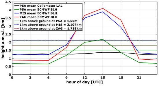
Figure 3.
Analysis daily BLH at PSA, MIS and ZAG and comparison to ceilometer LAL at PSA.
Figure 4 shows the averaged monthly LAL for PSA as well as the BLH for PSA, MIS and ZAG. Also for the annual course higher fluctuations in BLH can be observed in comparison to the detected LAL at PSA. While the monthly averaged LAL fluctuates between 1.1 km in January to 1.4 km in June, the BLH has its minimum in December with 0.9 m and its maximum with 1.4 km in June. A similar behavior can be observed for the average monthly BLH at MIS and ZAG where all mean values are generally higher in comparison to PSA (maximum mean BLH of 2.9 km for MIS and ZAG in July).
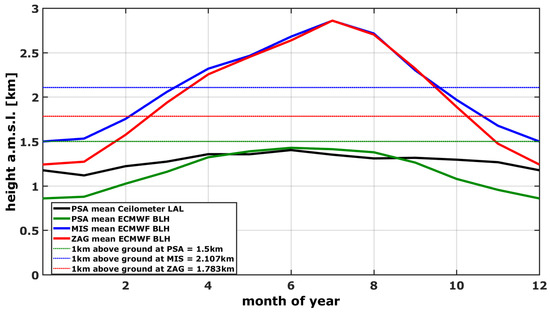
Figure 4.
Analysis mean monthly BLH at PSA, MIS and ZAG and comparison to ceilometer LAL at PSA.
4.1.3. Comparison of LIVAS Profile with Mean Ceilometer LAL and BLH of ECMWF at PSA
The available BLH from ECMWF as well as the LIVAS profile for PSA have been inter-compared to the on-site measurement data of LAL. The comparison is shown in Figure 5.
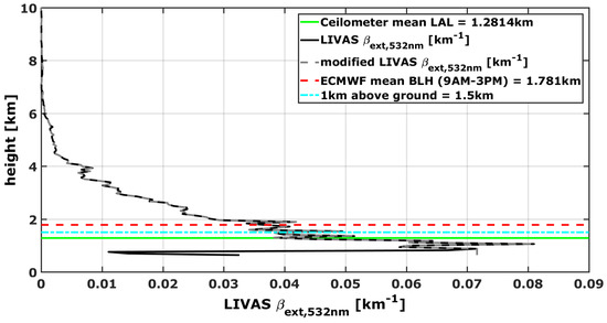
Figure 5.
Comparison of the LIVAS profile with mean LAL of ceilometer measurements and BLH of ECMWF at PSA.
The averaged detected LAL at PSA is displayed with a horizontal green solid line and lies at around 1.3 km a.m.s.l. The mean BLH for daytime (approximated as between 9:00 and 15:00, red broken curve) corresponds at PSA to about 1.8 km. It can be seen that both values lie above the largest peak in the LIVAS extinction profile which depicts a maximum of 0.081 km at about 1.0 km a.m.s.l.
4.2. Comparison of Average ABC Corrected for PSA, MIS and ZAG
Figure 6 displays the histogram of the DNI measured by the FS11 with ABC correction for all individually available data points (511,994 for PSA, 334,582 for MIS and 261,784 for ZAG from January 2015 until November 2017.
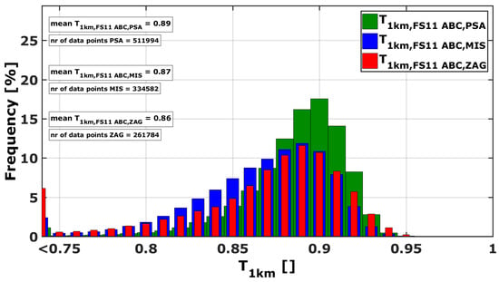
Figure 6.
Histogram of all available data points of ABC corrected for PSA, MIS and ZAG between January 2015 and November 2017.
The mean corrected at PSA lies around 0.89 from January 2015 until November 2017, while in MIS and ZAG a lower average of about 0.87 and 0.86 is found. Only considering the summer months (June, July and August) results in mean of 0.88 (PSA), 0.85 (MIS) and 0.84 (ZAG). Data points with lower than 0.75 occur more frequent in ZAG in comparison to the other two sites. Data points with between 0.8 and 0.9 are more frequent in MIS than in ZAG. This indicates that the overall level is higher in ZAG in comparison to MIS, but extreme events with higher aerosol particle loads lower the average in ZAG. All sites suffer from high dust loads during the summer months and an annual variation is the consequence. It can also be seen that the frequency distribution in MIS is wider in comparison to PSA and ZAG.
4.3. Transmittance Model Validation with ABC Corrected for PSA, MIS and ZAG
The three different TMs developed using the three extinction height profiles “H1000”, “LIVAS” and “BLH” have been compared to the site-dependent reference data between January 2015 and November 2017 for the sites PSA, MIS and ZAG.
4.3.1. Average of Transmittance Model
Figure 7 shows the averaged for all sites derived with the reference data set, as well as with the three TMs.
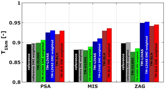
Figure 7.
The of the reference data set as well as the TMs for different assumptions for the extinction height profile. The DNI weighted mean is also shown. Only data points available at all sites at the same time between January 2015 and November 2017 have been evaluated.
Instead of considering a simple arithmetic average, the DNI weighted average of the can also be considered. The DNI weighted () is calculated with Formula (4):
using the integral over the whole time period.
It can be seen that for PSA, MIS and ZAG TM-H1000 fits best in the averaged as well as the DNI weighted in comparison to the reference. Applying TM-LIVAS and TM-BLH on on-site DNI measurements overestimates the mean at all three sites. Average derived with TM-BLH are 0.92, 0.93 and 0.94 and 0.93, 0.94 and 0.95 for DNI weighted for PSA, MIS and ZAG, respectively. The overestimation with TM-LIVAS is less pronounced than with TM-BLH at MIS but comparable at PSA and ZAG. The deviation of TM-LIVAS can be explained because the grid of the LIVAS extinction profiles is rather large ( grid) and the corresponding averaged profile does not represent the mean local conditions on site well (see also Figure 2). Figure 3 and Figure 4 show that the BLH does not describe the aerosol height distribution well throughout the whole day and year at PSA which might also be the case at the other sites.
4.3.2. Mean Bias Error and RMSE of
Figure 8 summarizes the absolute mean biased error (MBE) and root mean square error (RMSE) for each combination of extinction height model and site in comparison to the corresponding ABC corrected FS11 reference data set. The performance of the TM is site-dependent. This is the case as the extinction height profile, the main assumption of the TM, varies with a different extend at each site. Assuming a constant extinction profile (as in TM-H1000 and TM-LIVAS) therefore results in different deviations from the reference data set. It can be seen that the lowest MBE can be found for all sites with the TM-H1000 that assumes a constant extinction coefficient in the first kilometer above ground (0.33, −0.11 and −2.16% for PSA, MIS and ZAG, respectively). The lowest RMSE for PSA, MIS and ZAG are found with the modified LIVAS profile (4.6%, 6.8% and 5.7%, respectively).
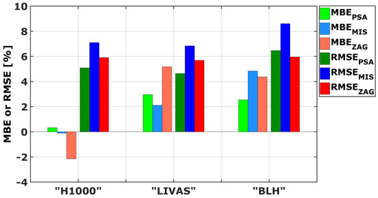
Figure 8.
Absolute MBE and RMSE of modeled for the validation of the TM for different assumptions for the extinction height profile in comparison to the according ABC corrected FS11 reference data set. Only data points available at all sites at the same time between January 2015 and November 2017 have been evaluated.
MBE and RMSE are increasing if the homogeneous extinction coefficient in the lowest layer above ground is scaled with the site- and time-dependent BLH data set. This is the case as increased BLHs result in lower extinction coefficients close to the ground and therefore increased . Figure 3 and Figure 4 showed that the BLH exceeds the measured LAL during daytime as well as during the summer months at PSA. This indicates that scaling the TM with BLHs results in an overestimation of in several cases especially during periods which are of interest for CSP due to high irradiation levels.
4.3.3. Annual Course of TM Performance
Figure 9, Figure 10 and Figure 11 show the averaged daily DNI-weighted as well as their 30 days moving average at PSA, MIS and ZAG calculated with all three TMs and in comparison to the reference derived from ABC corrected FS11 measurements. In this examination, all available data points for each site are analyzed individually. It has to be noted that the available data points are not uniformly distributed within the different sites and the days of the year. During the winter months less data points are used to calculate the DNI-weighted daily mean due to clouds masking the sun. The calculation of average DNI-weighted from the different models might be therefore less accurate. However, due to the higher levels in winter the absolute uncertainty of the model is lower than in summer for sunny timestamps. Also less data points are available in ZAG in comparison to PSA and MIS. The numbers of averaged data points are also shown in Figure 9, Figure 10 and Figure 11 and days with less than 100 data points are not considered in the analysis of averages and moving averages.
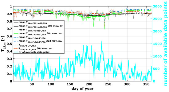
Figure 9.
Average daily DNI weighted for PSA from the ABC corrected measurements and the three different TMs and the 30 days moving average.
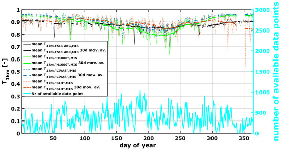
Figure 10.
Average daily DNI weighted for MIS from the ABC corrected measurements and the three different TMs and the 30 days moving average.
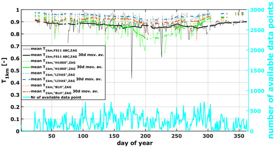
Figure 11.
Average daily DNI weighted for ZAG from the ABC corrected measurements and the three different TMs and the 30 days moving average.
For PSA, 30 days moving averaged DNI-weighted between 0.87 and 0.92 are derived from the reference data set (Figure 9). During summer months (May to September) the moving average derived with TM-H1000 underestimates from the reference data set and during winter it overestimates it slightly. This can be expected as both BLH as well as LAL show at PSA an annual course with higher values in summer and lower values in winter (see Figure 4). TM-BLH performs better during summer months. This could be explained by the fact that both the constant 1 km level as well as averaged BLH data for PSA lie closer to the mean on-site LAL measurements during these months, in comparison to the winter months (see also Figure 4). The TM-LIVAS overestimates the average throughout the whole year but performs better during summer months.
In MIS the reference data set shows lower during summer (less than 0.85) than during winter (more than 0.91) in the 30 days moving average (Figure 10). The averaged of both TM-LIVAS and TM-BLH fit well the averaged from the reference data set between June and August. During the remaining months of the year is overestimated by TM-LIVAS. TM-BLH underestimates during winter months, but is has to be noted that only few data points are available for this analysis during these months. TM-H1000 overestimates the reference during winter and underestimates it during summer months.
In ZAG a similar (in comparison to MIS) annual behavior of the averaged from the reference data set can be observed in the 30-days moving average (less than 0.85 during summer, more than 0.91 during winter, see Figure 11). It can be seen that all three TMs overestimate the average derived from the reference data set (except of TM-H1000 during summer). This indicates that the layer which includes the majority of aerosol particles and water vapor might be thicker than 1 km during these months. Also in ZAG is has to be considered that only few data points are available during winter months. The mean BLH for ZAG during July lies at around 2.860 m a.m.s.l., which is in a height of about 1.077 m above ground (see Figure 4).
4.4. Transmittance Model Sensitivity Analysis
Figure 12 shows the sensitivity of TM-H1000 concerning the thickness of the homogeneous layer above ground. The assumption about the extinction height profile within the TM has one of the largest impacts on the uncertainty of the TM ([21]). It can be seen that the sensitivity of TM-H1000 concerning the thickness of the homogeneous layer above ground is smallest for close to 0 and 1 (very hazy and very clear conditions). For derived with TM-H1000 around 0.5, the sensitivity of the result to the assumed homogeneous aerosol layer thickness is largest.
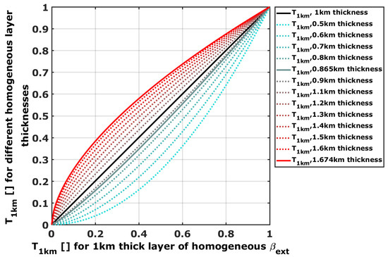
Figure 12.
for different aerosol layer thicknesses in which the extinction coefficient is considered homogeneous in TM-H1000.
This graph also shows that the absolute deviation of for different aerosol layer thicknesses larger and smaller 1 km is evenly distributed.
The solid red and gray curve display for TM assuming a thickness of 0.865 and 1.647, respectively. These values have been chosen as an example as they are the mean LAL and BLH at PSA at 15:00 (see Figure 3). This example shows that the range of lies between 0.89 and 0.93 for of 0.9 if the main contribution of aerosol particles and water vapor to extinction is in reality up to 0.865 or 1.647 km above ground at PSA instead of 1 km.
Considering a maximum deviation of 0.3 km from 1 km as aerosol layer thickness (0.7–1.3 km) will result in a deviation of less than 0.05 for larger 0.83. These results fit well to the uncertainty analysis from [21]. of less than 0.83 derived with the TM will therefore have larger uncertainties due to the considered aerosol layer thickness and will exceed the uncertainty of the reference data set (see [19]).
These considerations motivate to recommend additional site information (e.g., by on-site ABC corrected MOR measurements) for sites where the TM derives mean smaller than 0.83 as the deviations from might be larger than 0.05.
5. Conclusions
A model developed in [21] based on DNI measurements to derive the atmospheric transmittance in solar tower plants has been validated at three sites in Spain and Morocco. The transmittance model (TM) can be applied to the desired site during solar resource assessment as only data sets of usually available meteorological parameters like DNI, temperature, relative humidity and barometric pressure are necessary. Three different aerosol profiles have been tested to be applied as key assumption for the transmittance model development. In one approach it is assumed that all aerosol particles are homogeneously distributed within the first kilometer above ground. In a second approach, the aerosol profiles of the LIVAS database ([28]) are assumed to describe the vertical aerosol distribution. The third transmittance model uses the boundary layer height (BLH) of the ECMWF ERA-interim dataset ([29]) to scale the height above ground in which all aerosol particles are assumed to be distributed homogeneously.
The resulting broadband transmittance for a slant range of 1 km () from the three TMs for the sites of PSA in Spain, Missour, Morocco (MIS) and Zagora, Morocco (ZAG) is compared to a reference data set between January 2015 and November 2017. The reference data set consists of derived with on-site meteorological optical range (MOR) measurements and an applied absorption and broadband correction (ABC) according to [19].
The average for the sites PSA, MIS and ZAG are 0.89, 0.87 and 0.86 if all available data points for each site individually are analyzed. at the semi-desert sites of Morocco shows a more pronounced annual variation in comparison to PSA in Spain. It has to be noted that for plant yield simulations, it is recommended to include an extinction or transmittance time series instead of arithmetic averages. If averages are used, the DNI weighted average of the transmittance data should be utilized.
The validation of the TM showed that the absolute mean bias error (MBE) for all three TMs and sites lies below 5% except for ZAG and the usage of the according LIVAS profile. Assuming that all aerosol particles are homogeneously distributed within the first kilometer above ground results in a reduction of MBE to almost 0 in PSA and MIS. The absolute root mean square error (RMSE) of the TM is around 5–6% except of for the site of MIS (around 7–8%). An analysis of the BLH data shows strong diurnal and annual courses for all three sites. The difference between minimal and maximal BLH within a day or year is largest in ZAG. Higher BLH during midday and summer months due to higher temperatures close to the ground and the induced vertical mixing results in lower extinction coefficients close to the ground (and therefore higher ) derived with the TM. The performance of the TM is site-dependent as adequate site-dependent information about the aerosol height profile is the key assumption within the TM.
It can be noted that the TM performs better during summer months than during winter, but it has to be mentioned that more data points have been available during summer for this validation.
The TM is most sensitive for the approximation of the aerosol particle distribution within the lower atmosphere. Three approaches have been compared to be applied within the TM. It can be concluded that the TM performs similarly well, assuming a homogeneous aerosol distribution in the lowest kilometer above ground or the extinction profile extracted from the LIVAS climatology. Using BLH data to describe the height under which the aerosol particles are homogeneously distributed and above which no aerosol particles can be found results in the overestimation of at all sites.
The validation of the TM showed its applicability at various sites. Hazy sites can be identified with the TM but additional ground measurements of , e.g., ABC corrected MOR measurements, are recommended in this case. This is recommended as the increased uncertainty of the TM for lower can result in an underestimation of atmospheric transmittance at a certain site. Sites with of more than 0.83 can be verified with the TM and the TM can be considered as providing sufficient site information for resource assessment for clear sites.
Author Contributions
Conceptualization and methodology: N.H. and S.W. Data analysis: N.H. Software: N.H., M.S. and S.W. Resources and data curation: N.H., A.G., A.A.M., F.W., L.Z. and A.S. Writing—Original Draft preparation: N.H. and S.W. Interpretation of results, Writing—Review and Editing: all the authors. Supervision and project administration: S.W.
Funding
The authors would like to thank the Helmholtz Association for funding the project “Impact of Desert Environment on Solar Energy Systems” (DESERGY) (PD-205).
Acknowledgments
We also acknowledge the developers of libRadtran. The authors thank the Group of Atmospheric Optics, Valladolid University, for the provision of the CÆLIS tool (http://www.caelis.uva.es) used in this publication and the AERONET, PHOTONS and RIMA staff for their support.
Conflicts of Interest
The authors declare no conflict of interest. The funders had no role in the design of the study, in the collection, analyses, or interpretation of data, in the writing of the manuscript, or in the decision to publish the results.
Abbreviations
The following abbreviations are used in this manuscript:
| ABC | absorption and broadband correction |
| afglms | mid-latitude summer standard atmosphere |
| AOD | aerosol optical depth |
| BLH | boundary layer height |
| CSP | concentrated solar power |
| DNI | direct normal irradiance |
| ECMWF | European Centre for Medium-Range Weather Forecasts |
| EPC | engineering, procurement and construction |
| LAL | lowest aerosol layer |
| MBE | mean bias error |
| MIS | Missour, Morocco |
| MOR | meteorological optical range |
| PSA | Plataforma Solar de Almería |
| RMSE | root mean square error |
| SZA | solar zenith angle |
| broadband transmittance for a slant range of 1 km | |
| TMY | typical meteorological year |
| TM | transmittance model |
| ZAG | Zagora, Morocco |
References
- IRENA. Africa 2030: Roadmap for a Renewable Energy Future; Technical report; International Renewable Energy Agency: Abu Dhabi, UAE, 2015. [Google Scholar]
- Hanrieder, N. Determination of Atmospheric Extinction for Solar Tower Plants. Ph.D. Thesis, RWTH Aachen University, DLR, Aachen, Germany, 2016. [Google Scholar]
- Hanrieder, N.; Wilbert, S.; Mancera Guevara, D.; Buck, R.; Giuliano, S.; Pitz-Paal, R. Atmospheric extinction in solar tower plants—A review. Sol. Energy 2017, 152, 193–207. [Google Scholar] [CrossRef]
- Ballestrín, J.; Carra, M.E.; Enrique, R.; Monterreal, R.; Fernández-Reche, J.; Polo, J.; Casanova, M.; Barbero, F.; Marzo, A. Diagnosis of a lambertian target in solar context. Measurement 2018, 119, 265–269. [Google Scholar] [CrossRef]
- Ballestrín, J.; Monterreal, R.; Carra, M.; Fernández-Reche, J.; Polo, J.; Enrique, R.; Rodríguez, J.; Casanova, M.; Barbero, F.; Alonso-Montesinos, J.; et al. Solar extinction measurement system based on digital cameras. Application to solar tower plants. Renew. Energy 2018, 125, 648–654. [Google Scholar] [CrossRef]
- Sánchez, M.; Fernández-Peruchena, C.; Bernardos, A.; Chueca, R.; Sainas, I. High-accuracy real-time monitoring of solar radiation attenuation in commercial solar towers. In Proceedings of the SolarPACES 2018, Casablanca, Morocco, 2–5 October 2018. [Google Scholar]
- Elias, T.; Ramon, D.; Dubus, L.; Brau, J.; Langouet, H. Instrumental Set-up to Estimate the Atmospheric Attenuation along the Slant Path of Concentrated Solar Plants. In Proceedings of the Poster, SolarPACES 2017, Santiago de Chile, Chile, 26–29 September 2017; Available online: https://aip.scitation.org/doi/10.1063/1.5067190 (accessed on 3 May 2019).
- Barbero, F.; Alonso-Montesinos, J.; Batlles, F.; Polo, J.; López, G.; Bosch, J.; Ballestrín, J.; Carra, E.; Fernández-Reche, J. Evolution of the aerosol extinction coefficient at 100 m above ground during an episode of Saharan dust intrusion as derived from data registered by a ceilometer in Almería (SE Spain). In Proceedings of the SolarPACES 2018, Casablanca, Morocco, 2–5 October 2018. [Google Scholar]
- Elias, T.; Ramon, D.; Garnero, M.A.; Dubus, L.; Bourdil, C. Solar energy incident at the receiver of a solar tower plant, derived from remote sensing: Computation of both DNI and slant path transmittance. In Proceedings of the SolarPACES 2017, Santigo de Chile, Chile, 26–29 September 2017. [Google Scholar]
- Lopez, G.; Gueymard, C.; Bosch, J.L. Evaluation of solar energy losses for the heliostat-to-receiver path of a tower solar plant for different aerosol models. In Proceedings of the Solar World Congress 2017, Abu Dhabi, UAE, 29 October–2 November 2017. [Google Scholar]
- Gueymard, C.; Lopez, G.; Rapp-Arraras, I. Atmospheric transmission loss in mirror-to-tower slant ranges due to water vapor. In Proceedings of the SolarPACES 2016, Abu Dhabi, UAE, 11–14 October 2016. [Google Scholar]
- Lopez, G.; Gueymard, C.; Bosch, J.L.; Rapp-Arraras, I.; Alonso-Montesinos, J.; Pulido-Calvo, I.; Ballestrín, J.; Polo, J.; Barbero, J. Modeling water vapor impact on the solar energy reaching the receiver of a solar tower plant by means of artificial neural networks. Sol. Energy 2018, 169, 34–39. [Google Scholar] [CrossRef]
- Carra, E.; Ballestrín, J.; Polo, J.; Barbero, F.; Fernández-Reche, J. Atmospheric extinction levels of solar radiation at Plataforma Solar de Almería. Application to solar thermal electric plants. Energy 2018, 145, 400–407. [Google Scholar] [CrossRef]
- Polo, J.; Ballestrín, J.; Carra, E. Sensitivity study for modelling atmospheric attenuation of solar radiation with radiative transfer models and the impact in solar tower plant production. Sol. Energy 2016, 134, 219–227. [Google Scholar] [CrossRef]
- Polo, J.; Alonso-Montesinos, J.; López-Rodriguez, G.; Bosch, J.; Barbero, F.; Carra, E.; Fernández-Reche, J.; Batlles, F.; Ballestrín, J. Modelling atmospheric attenuation at different AOD time-scales in yield performance of solar tower plants. In Proceedings of the SolarPACES 2018, Casablanca, Morocco, 2–5 October 2018. [Google Scholar]
- Polo, J.; Ballestrín, J.; Alonso-Montesinos, J.; López-Rodriguez, G.; Barbero, F.; Carra, E.; Fernández-Reche, J.; Bosch, J.; Batlles, F. Analysis of solar tower plant performance influenced by atmospheric attenuation at different temporal resolutions related to aerosol optical depth. Sol. Energy 2018, 157, 803–810. [Google Scholar] [CrossRef]
- Mancera Guevara, D.; Schrödter-Homscheidt, M.; Popp, T.; Heinemann, D. Vertical aerosol concentrations in the lowest 300m of the troposphere for Solar Tower Plants assessment from CALIPSO satellite and ECMWF-MACC data. In Proceedings of the SolarPACES 2017, Santiago de Chile, Chile, 26–29 September 2017. [Google Scholar]
- Elias, T.; Ramon, D.; Brau, J.; Moulana, M. Sensitivity of the solar resource in solar tower plants to aerosols and water vapor. In Proceedings of the SolarPACES 2018, Casablanca, Morocco, 2–5 October 2018. [Google Scholar]
- Hanrieder, N.; Wilbert, S.; Pitz-Paal, R.; Emde, C.; Gasteiger, J.; Mayer, B.; Polo, J. Atmospheric extinction in solar tower plants: Absorption and broadband correction for MOR measurements. Atmos. Meas. Tech. 2015, 8, 1–14. [Google Scholar] [CrossRef]
- Schüler, D.; Wilbert, S.; Geuder, N.; Affolter, R.; Wolfertstetter, F.; Prahl, C.; Röger, M.; Schroedter-Homscheidt, M.; Ghennioui, A.; Allah Guizani, A.; et al. The enerMENA Meteorological Network—Solar Radiation Measurements in the MENA region. AIP Conf. Proc. 2016, 1734, 150008. [Google Scholar]
- Hanrieder, N.; Sengupta, M.; Xie, Y.; Wilbert, S.; Pitz-Paal, R. Modelling beam attenuation in solar tower plants using common DNI measurements. Sol. Energy 2016, 129, 244–255. [Google Scholar] [CrossRef]
- Sengupta, M.; Wagner, M. Estimating atmospheric attenuation in central receiver systems. In Proceedings of the ASME 2012 6th International Conference on Energy Sustainability, San Diego, CA, USA, 23–26 July 2012. [Google Scholar]
- Sengupta, M.; Wagner, M. Atmospheric attenuation in central receiver systems from DNI measurements. In Proceedings of the SolarPACES 2012, Marrakech, Morocco, 11–14 September 2012. [Google Scholar]
- Sengupta, M.; Wagner, M. Impact of aerosols on atmospheric attenuation loss in central receiver systems. In Proceedings of the SolarPACES 2011, Granada, Spain, 20–23 September 2011. [Google Scholar]
- Mayer, B.; Kylling, A. Technical note: The libRadtran software package for radiative transfer calculations—Description and example of use. Atmos. Chem. Phys. 2005, 5, 1855–1877. [Google Scholar] [CrossRef]
- Emde, C.; Buras-Schnell, R.; Kylling, A.; Mayer, B.; Gasteiger, J.; Hamann, U.; Kylling, J.; Richter, B.; Pause, C.; Dowling, T.; et al. The libRadtran software package for radiative transfer calculations (version 2.0.1). Geosci. Model Dev. 2016, 9, 1647–1672. [Google Scholar] [CrossRef]
- Hanrieder, N.; Ghennioui, A.; Wiesinger, F.; Schade, A.; Wilbert, S. Atmospheric extinction in CSP tower plants in Morocco and Spain. In Proceedings of the SolarPACES 2017, Santigo de Chile, Chile, 26–29 September 2017. [Google Scholar]
- Amiridis, V.; Marinou, E.; Tsekeri, A.; Wandinger, U.; Schwarz, A.; Giannakaki, E.; Mamouri, R.; Kokkalis, P.; Binietoglou, I.; Solomos, S.; et al. LIVAS: A 3-D multi-wavelength aerosol/cloud climatology based on CALIPSO and EARLINET. Atmos. Chem. Phys. Discuss. 2015, 15, 2247–2304. [Google Scholar] [CrossRef]
- Berrisford, P.; Dee, D.; Poli, P.; Brugge, R.; Fielding, K.; Fuentes, M.; Kallberg, P.; Kobayashi, S.; Uppala, S.; Simmons, A. The ERA-Interim Archive Version 2.0; Technical Report; ECMWF: Reading, UK, 2011. [Google Scholar]
- Lufft Mess-und Regeltechnik, G. Manual Ceilometer CHM 15k “NIMBUS"; Lufft: Fellbach, Germany, 2015. [Google Scholar]
- Koschmieder, H. Theorie der horizontalen Sichtweite. Beitr. Phys. Freien Atmos. 1924, 12, 33–53, 171–181. [Google Scholar]
- Griggs, D.; Jones, D.; Ouldridge, M.; Sparks, W. Instruments and Observing Methods. Report No. 41. The First WMO Intercomparison of Visibility Measurements, Final Report; Technical Report; World Meteorological Organisation: South Yorkshire, UK, 1989. [Google Scholar]
- Vaisala. User’s Guide: Present Weather Sensor FS11P; Manual; Vaisala: Vantaa, Finland, 2010. [Google Scholar]
- Anderson, G.; Clough, S.; Kneizys, F.X.; Chetwynd, J.; Shettle, E. AFGL Atmospheric Constituent Profiles (1–120 km); Environmental Research Papers, AFGL-TR-89-0110; Air Force Research Laboratory: Hanscom, MA, USA, 1986; Volume 954. [Google Scholar]
- Holben, B.; Eck, T.; Slutsker, I.; Tanré, D.; Buis, J.; Setzer, A.; Vermote, E.; Reagan, J.; Kaufman, Y.; Nakajima, T.; et al. AERONET—A federated instrument network and data archive for aerosol characterization. Remote Sens. Environ. 1998, 66, 1–16. [Google Scholar] [CrossRef]
- Hess, M.; Köpke, P.; Schult, I. Optical properties of aerosols and clouds: The software package OPAC. Bull. Am. Soc. 1998, 79, 831–844. [Google Scholar] [CrossRef]
- ECMWF, E.C.f.M.R.W.F. Operational Implementation 11 July 2017. Part IV: Physical Processes; European Centre for Medium-Range Weather Forecasts: Reading, UK, 2017. [Google Scholar]
- Dee, D.; Uppala, S.; Simmons, A.; Berrisford, P.; Poli, P.; Kobayashi, S.; Andrae, U.; Balmaseda, M.; Balsamo, G.; Bauer, P.; et al. The ERA-Interim reanalysis: Configuration and performance of the data assimilation system. Q. J. R. Meteorol. Soc. 2011, 137, 553–597. [Google Scholar] [CrossRef]
- Troen, I.; Mahrt, L. A simple model of the atmospheric boundary layer; sensitivity to surface evaporation. Bound. Layer Meteorol. 1986, 37, 129–148. [Google Scholar] [CrossRef]
- Seidel, D.; Zhang, Y.; Beljaars, A.; Golaz, J.C.; Jacobson, A.; Medeiros, B. Climatology of the planetary boundary layer over the continental United States and Europe. J. Geophys. Res. 2012, 117, D17106. [Google Scholar] [CrossRef]
© 2019 by the authors. Licensee MDPI, Basel, Switzerland. This article is an open access article distributed under the terms and conditions of the Creative Commons Attribution (CC BY) license (http://creativecommons.org/licenses/by/4.0/).