Abstract
Green hydrogen production using membrane electrode assembly (MEA) has attracted significant attention due to its remarkable energy conversion efficiency. To further enhance its sustainability, MEA-based water electrolysis can be integrated with renewable solar energy by adopting a photocatalytic MEA (P-MEA) system, incorporating light-transmitting windows into MEA stacks, and employing suitable photocatalytic electrode materials. A critical challenge lies in developing cost-effective and high-performance photocatalytic electrode materials by replacing conventional noble material systems with earth-abundant photocatalytic electrode materials. This review discusses recent advances in P-MEA concepts and fabrication strategies for photoelectrodes tailored to MEA operation. Particular emphasis is placed on elucidating the mechanisms of light-induced charge dynamics that govern the P-MEA-based water electrolysis process. Overall, this review highlights the synergistic potential of integrating photocatalysis with MEA-based water electrolysis to advance sustainable green hydrogen production.
1. Introduction
The global climate change crisis intensifies due to greenhouse gas (GHG) emissions from fossil fuels. Thus, the transition of sustainable energy sources has garnered worldwide attention. Renewable green hydrogen has emerged as a promising sustainable energy source from solar light, with zero carbon emissions [1,2,3,4,5,6]. Hydrogen can be categorized into various types depending on its production methods and the associated CO2 emissions in each process [7]. Among them, green hydrogen production without CO2 emission using photo/electrolysis is a great candidate for meeting the demand of the energy transition towards global carbon neutrality. Consequently, the development of cost-effective green hydrogen production systems has become an increasing research interest in recent years. From this perspective, the utilization of solar energy appears an ideal concept for realizing carbon-free green hydrogen production by engineering semiconducting materials as an artificial leaf in integrated photovoltaic (PV)/photoelectrochemical (PEC) water splitting, and so on [8,9,10]. However, due to its low production efficiency, researchers have devised an alternative approach to green hydrogen production using a membrane electrode assembly (MEA) system for large-scale hydrogen production.
As the efficient MEA system depends on many factors, the interface interaction between MEA and the catalysts used is a critical factor that remains a significant challenge. Up to now, although the improvement of the interface interaction between the catalyst layer and the membrane has been increasingly focused on, the stability and durability of the catalyst used have been less discussed [11]. As noble and precious metals/metal oxides are still applied for both the cathode and anode, green hydrogen production through this method remains challenging to achieve at an industrial scale, which is over 7 on the technology readiness level (TRL) in terms of laboratory-scale development [12,13]. However, few studies on alternative, earth-abundant catalysts and appropriate system design have been reported. Beginning to address the efficient and stable replacement of catalysts, thereby reducing the bias overpotential of electrode materials in the MEA system, which requires a low or zero bias potential, would be a beneficial step toward a practical solution. Moreover, it is essential for photocatalytic electrode materials to have controlled geometric features and morphology for strong interface interaction with the membrane. At the same time, adapting the MEA system to utilize a sustainable light energy source would enhance the efficiency and stability of hydrogen production.
To support future research, this review systematically outlines key developments and highlights promising photocatalyst-employed light-responsive MEA systems. In our discussion, we aim to raise research awareness on overcoming existing challenges through three main approaches. We suggest the most promising fabrication technique for P-MEA from our perspective by determining the necessary factors of well-arranged interface interaction in an MEA system. We provide insights into an alternative light-responsive MEA system architecture design, and followed with a brief discussion on understanding the mechanism. Consequently, we emphasize the advanced modification of photocatalytic electrode materials for the P-MEA system, which is especially feasible for utilizing renewable solar energy.
2. Basic Principles of MEA-Based Water Electrolysis
2.1. Concepts of MEA-Based Water Electrolysis
The simple fabrication procedure of a standard MEA system is primarily designed for convenience, allowing for operation under dark conditions with a continuous water supply, stable temperature, and external potential. This is illustrated in Figure 1, and Table 1 provides a detailed explanation of the required system stacks [14].
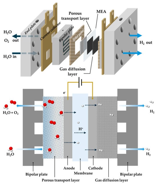
Figure 1.
Schematic showing MEA components and MEA water electrolysis mechanism.

Table 1.
MEA system components and their properties.
In MEA-based water electrolysis, oxygen is evolved in the anode side with some of the unsplit water under a high bias potential. On the other hand, an oxidized proton from the anode passes through the membrane, commonly Nafion in acidic condition, which is the proton exchange membrane, to the cathode to release hydrogen. The operating principle of MEA water electrolysis, including the anodic and cathodic reactions, is depicted below [15].
MEA is a feasible and effective mediator for producing high-purity hydrogen. However, high kinetic energy is required to drive the redox reaction in hydrogen production. The basic operation mechanism in MEA water electrolysis is further described in the next section.
2.2. Basic Operation Mechanism of MEA-Based Water Electrolysis
In a standard MEA system, hydrogen production is operated through an electrochemical process that requires input fuel, catalysts, pressure, and heat. Furthermore, as many studies have provided, as primarily described in Figure 2, the high DC potential was applied across the system to finally release H2 via water splitting [16]. In terms of catalyst materials, precious rare-earth materials IrO2 and Pt are the most commonly applied catalysts for the anode and cathode, respectively, as they are the most durable materials under high bias potential discovered so far [17].
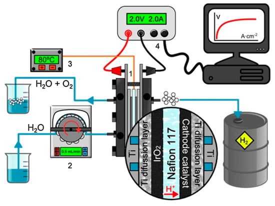
Figure 2.
MEA-based water electrolysis setup: (1) MEA-based water electrolysis system, (2) peristaltic pump and water reservoir, (3) temperature controller, and (4) computer-controlled DC power supply. Reprinted with permission from ref. [16]: Copyright 2019, Catalysis Today.
Inclusively, the efficiency of the MEA-based water electrolysis system depends on many factors, while the gas diffusion layer (GDL), the fabrication of MEA, and the catalysts used are prior factors. Among these, the fabrication of MEA and the development of catalysts are the main challenges remaining for the hydrogen production technology of MEA systems. The current commercially applied MEA fabrication technique, an ink-based electrode spraying technique, is on the verge of being established in production facilities for MEA manufacturing [18]. MEA fabrication mainly involves two different materials: a catalyst-coated substrate (CCS), on which the catalysts of the ink or slurries are applied to the GDL/PTL, and the catalyst-coated membrane (CCM), on which the ink catalysts are coated directly onto the membrane. The application of either material is followed by hot-pressing the CCS with a membrane or CCM with the GDL/PTL to form a complete MEA layer, as detailed in Figure 3.
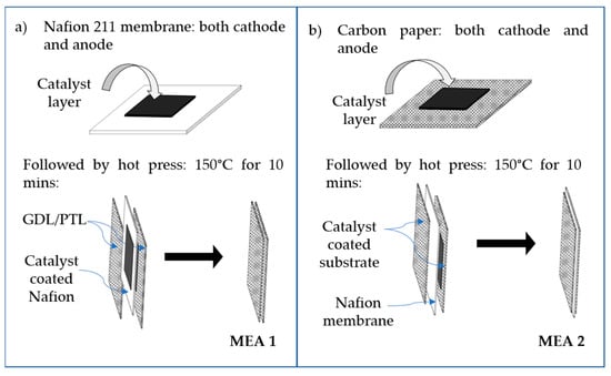
Figure 3.
Schematic showing two different MEA preparation approaches: (a) catalyst-coated membrane (CCM) and (b) catalyst-coated substrate (CCS).
3. Challenges and Strategies of MEA-Based Water Electrolysis
As mentioned before, current MEA fabrication methods are primarily ink spraying and drop casting, which is followed by hot-pressing or steam pressing [19,20]. These methods pose stability issues, such as through materials fouling and poor interface interaction, which lead to the physical deterioration of the MEA. Moreover, a continuous high bias potential eventually degrades the catalytic electrode materials under long-term operation conditions, resulting in unstable MEA hydrogen production. This hinders the technological readiness of the MEA system, preventing commercial hydrogen production. Thus, an MEA system that has low or zero bias potential is urgently needed. MEA-based water electrolysis under low potential utilizing solar light energy as a sustainable energy source is promising. The absorbed light energy suppresses overpotentials in the current MEA system, thus facilitating efficient hydrogen production.
Solar light energy may be employed to address existing challenges in standard MEA-based water electrolysis; doing so requires the following:
- Proper photocatalytic electrode materials;
- A suitable MEA deposition technique for P-MEA;
- A promising P-MEA system design.
Last but not least, understanding the mechanism of photocatalytic electrode materials in the P-MEA system would help us effectively cope with and benefit from the proposed P-MEA.
3.1. Photocatalytic MEA (P-MEA) Fabrication
3.1.1. Challenges in P-MEA Fabrication
Before delving into a deeper explanation, it is essential to understand the working mechanism of P-MEA and its differences from standard MEA. Figure 4 illustrates the concept of the two distinct working mechanisms, where a high bias potential is required for standard MEA operation. In contrast, a light energy source alleviates the requirement for a high bias potential in P-MEA. A light energy source is used because it is vital for the easy passage of the charge transfer and to facilitate the mass transport of the incident photon through the P-MEA. The transition from standard MEA to P-MEA requires the use of a sustainable light energy source instead of a high bias potential, which poses challenges and difficulties. Moreover, a summary of these challenges and strategies is provided in a previous section.
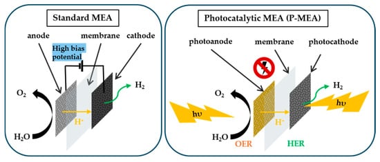
Figure 4.
Schematic showing the working mechanism of standard MEA and P-MEA in water electrolysis.
The operating principle of P-MEA-based water electrolysis, including anodic and cathodic reactions, is as follows [21,22]: In P-MEA-based water electrolysis, the driving force of the reaction originates from a photon energy source. In this process, the application of a high bias potential could be neglected. Catalyst degradation due to the high bias potential in standard MEA could be avoided. If the required considerations according to the previous proposed strategies are successfully adapted, the future of P-MEA-based water electrolysis would enable commercial hydrogen production.
Consequently, as mentioned before, the required improvements on surface interaction between the catalyst layer (CL) and the membrane are addressed in Table 2 by considering various aspects for P-MEA fabrication, such as catalysts with electro/photo-responsivity, a tunable structure for proper mass transports, and effective surface interaction with reduced fouling and peeling between the CL and the membrane. In essence, P-MEA should exhibit strong interfacial integration and excellent chemical compatibility, resulting in a synergistic photocatalytic effect. This will enable the efficient transfer of H+ ions while balancing proton and oxygen transport, promoting overall catalytic performance and stability beyond the standard MEA achievement alone. For this purpose, there are two essential strategies that need to be considered in P-MEA fabrication: the photonic, electronic, and physical crystal structure engineering of the photocatalytic electrode materials and a promising P-MEA deposition technique.

Table 2.
Requirements for strong interface interaction.
3.1.2. Photocatalytic Electrode Materials for P-MEA
For enhanced photocatalytic performance in P-MEA, the photocatalytic electrode materials are required to have a wide bandgap for efficient light absorption and harvesting, favorable band alignment for fast charge separation and kinetic reactions, and controllable geometric features and morphology for maximizing ion/mass transport and increasing active sites. By optimizing the electronic and physical properties of photocatalytic electrode materials, one can significantly increase light harvesting, charge carrier separation, and overall reaction kinetics. As described in Figure 5, three key strategies are adopted in the engineering of photocatalytic electrode materials [23]:
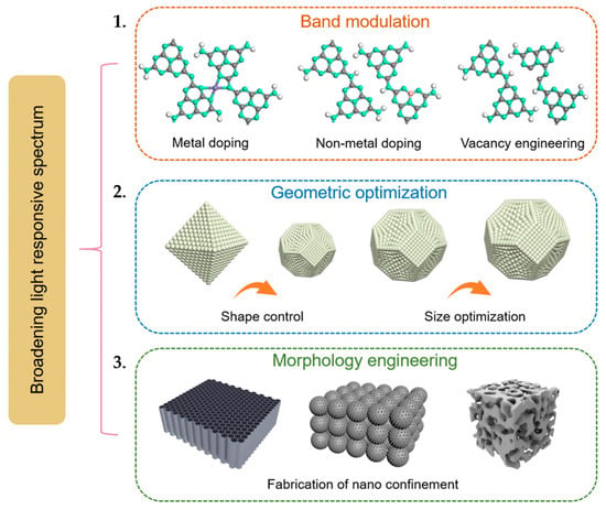
Figure 5.
Schematic of the structure engineering design of photocatalysts for P-MEA: (1) Band modulation of a semiconductor. (2) Geometric optimization. (3) Morphology engineering. Reprinted with unrestricted permission from ref. [23]: Copyright 2023, Materials Today.
- Band modulation of electrode materials;
- Geometric optimization;
- Morphology engineering.
In band modulation, the main strategy involves adjusting the electronic band structure of semiconductors to extend their light absorption range. By narrowing the bandgap through element doping (e.g., nitrogen, sulfur, or metal doping), heterojunction formation, or defect engineering, the absorption edge can be shifted into a visible or near-infrared region, allowing for better utilization of sunlight. As shown in Figure 6a, both metal Ni doping and non-metal C doping of polymeric carbon nitride (PCN) lead to band alignment in their electronic band structure. Such doping engineering can enhance the photocatalytic performance of certain intrinsic drawbacks in PCN. As the doping materials increase the surface-active areas, they improve the charge migration rate and thus slow down the recombination of electron-hole pairs [24,25]. Additionally, vacancy engineering in perovskite oxide is shown in Figure 6b with La1−xSrxCo1−yFeyO3−δ (LSCF), is an approach with two perovskites, LSCF, and a three-dimensionally ordered microporous (3DOM) structure; it facilitates the access of reactants by creating more reactive sites for faster charge transfer and ion transport [26].
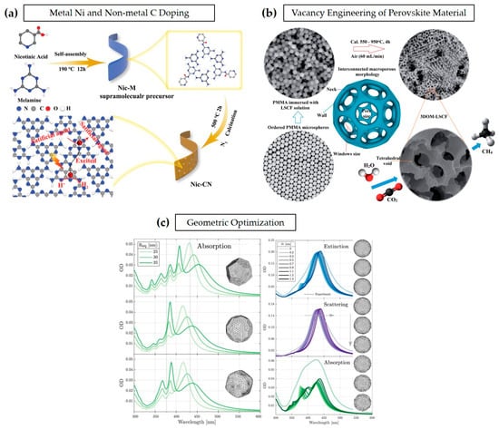
Figure 6.
Band modulation through (a) metal Ni and non-metal doping for improving hydrogen production. Reprinted with permission from ref. [24]: Copyright 2021, Small. (b) Vacancy engineering of LSCF perovskite material for enhanced CO2 reduction. Reprinted with permission from ref. [26]: Copyright 2016, Journal of Materials Chemistry A. (c) Light absorption improvement through geometric optimization. Reprinted with permission from ref. [27]: Copyright 2019, Analytical Chemistry, American Chemical Society.
Photonic crystal structures and the incorporation of plasmonic nanoparticles enhance light trapping through multiple reflections and localized surface plasmon resonance (LSPR) effects, effectively increasing light harvesting/utilization and improving charge carrier dynamics. Furthermore, Figure 6c shows the study of how the light absorption of photocatalytic electrode materials largely depends on the geometric features of their structure. The geometric structures of the materials are generally controlled at nanometer scale. Different geometric features are formed based on the difference in the silver nanoparticles’ size, specifically 25 nm, 30 nm, and 35 nm. Their respective results arise from imperfections in growth, governed by the growth mechanism, and the generation of faceted particles. The surface roughness of an average radius NP has a different roughness depending on its local radius deviation, which is expressed by the degree of roughness, denoted in Figure 6c as δr. Faceting and surface roughness determine the optical properties of the plasmonic nanoparticles (NPs). Each faceting type introduces respective resonances in the optical response of the NPs, and the surface roughness induces a shift in the spheres that determines their absorption spectrum. This study suggests that both facets and surface roughness play roles in the absorption spectrum of the NPs [27]. In addition, morphology engineering further enhances photocatalytic efficiency by tailoring the surface structure and porosity of photocatalysts. Consequently, the advantages and necessity of high-reaction sites in water electrolysis are described in an electrochemical surface area. To meet the required aspects for strong interface interaction, it is typically crucial to enhance the electrochemical surface area (ECSA) of the catalytic materials in MEA, especially for P-MEA. As shown in Equation (1), catalyst loading is a critical parameter for enhancing ECSA [28,29,30,31]. Thus, selecting a suitable deposition technique that can control both the catalyst loading and the thickness of the CL is necessary. Before that, it is essential to focus on improving and harnessing catalyst materials, especially photocatalysts, as proposed earlier.
where Lcatalyst is the catalyst loading, is the exchange current density based on the ECSA, and QH is the hydrogen adsorption charge, which can be obtained via cyclic voltammetry, or the galvanostatic charging method.
In the following, Figure 7a highlights the critical role of catalyst layer morphology and structural integration in optimizing photocatalytic membrane electrode assemblies (P-MEAs). The balance of hydrophilic/hydrophobic supports and ionomer thickness dictates proton and oxygen transport, where flooded layers favor proton conduction but restrict oxygen diffusion, and dry layers enhance oxygen pathways but limit proton transfer. Hierarchical pore structures (micro-, meso-, and macropores), along with engineered architectures such as nanosheets, core–shell structures, and 3D porous networks, improve mass transport, light harvesting, and active site availability [32]. Moreover, in Figure 7b, while conventional MEAs consist of discrete catalyst layers separated by a membrane, the integrated catalyst-coated membranes (CCMs) reduce ohmic resistance and enhance charge transport, enabling higher-current-density operation [33]. Thus, all-in-one P-MEAs offer superior efficiency by combining morphology control, band structure modulation, and geometric optimization to maximize light absorption and charge transport, paving the way for advanced solar-driven hydrogen production.
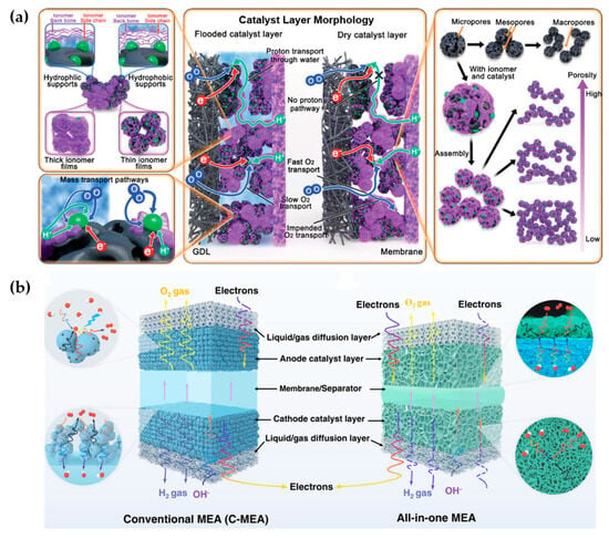
Figure 7.
Schematics of (a) the catalyst layer morphology, reactant transport pathways, structure, and factors that impact performance. Reprinted with unrestricted permission from ref. [32]: Copyright 2021, ADVANCED ENERGY MATERIALS. (b) Conventional MEA and all-in-one MEA based on 3D-ordered transport highways. Reprinted with unrestricted permission from ref. [33]: Copyright 2022, Nature Communications.
3.1.3. Suitable Deposition Technique for P-MEA
As shown in Table 3, P-MEA fabrication is conducted through various techniques. At the same time, the catalyst ink spray coating method has been widely applied so far due to its favorable characteristics compared to other techniques [34]. However, as mentioned before, catalyst ink spraying techniques have several critical disadvantages, including dense catalytic agglomeration, the ionomer occupying catalytic active sites, and the fouling of the catalysts. These occurrences decrease gas–liquid mass transfer, electrical conductivity, and electrolysis stability. Thus, an effective P-MEA fabrication technique is required, for which the catalyst layer is highly ordered and the membrane/CL interfaces have large active sites.

Table 3.
Types of P-MEA preparation techniques.
Table 3 categorizes various P-MEA fabrication techniques into four main application categories: application in solid form, vapor phase deposition, electrode-assisted deposition, and application in precursor state. Each category presents distinct trade-offs in terms of waste generation, processing time, and overall CL quality. In terms of CL quality evaluation standards, the uniformity in morphology, surface coverage and porosity, adhesion strength, catalytic activity per area, durability, and electrochemical integrity are considered. Solid-form applications, such as dry spraying and decal methods, are relatively simple and cost-effective. However, these techniques often suffer from limitations in catalyst dispersion and interfacial contact quality, resulting in lower overall performance. Decal methods offer slightly improved structural integrity and interfacial bonding, but still fall short in producing uniformly distributed catalyst layers. In contrast, vapor phase deposition techniques, such as magnetron sputtering and chemical vapor deposition (CVD), deliver moderate to high-quality catalyst layers due to better control over material growth and layer thickness. These methods generally produce more uniform coatings and tighter interfaces, improving performance metrics such as mass activity and power density, although they may be more time-consuming. Electrode-assisted deposition methods, including electro-deposition, electro-spraying, and electrophoretic deposition, offer improved control over catalyst-layer morphology and porosity. These techniques enable tailored layer architecture, resulting in enhanced mass transport and reduced catalyst usage. However, challenges in scalability and reproducibility still limit their industrial adoption. Among the precursor state application techniques, atomic layer deposition (ALD) stands out as the most advanced and effective method. ALD provides exceptional control at the atomic scale, enabling the deposition of ultra-thin, conformal catalyst layers with minimal material waste. Unlike other techniques, ALD facilitates precise layer-by-layer growth, resulting in superior catalytic dispersion, optimized proton/electron pathways, and highly durable interfaces. This method consistently yields the highest-quality MEAs, as indicated in Table 3. Significantly, while ALD is moderately time-consuming, its advantages in catalyst utilization, structural precision, and electrochemical performance outweigh the time cost. Recent studies have demonstrated that ALD-fabricated MEAs can achieve enhanced power output with ultralow platinum loadings, making this technique especially attractive for P-MEA fabrication.
Technically, the conformality of the catalyst layer coating on the membrane is desired for improved surface interaction between the membrane and the catalysts. In Figure 8a, we propose the desired catalyst layer coating for the membrane structure without the intrusion of the catalysts into the membrane structure, conformally coated on the membrane. Conformal coating via atomic layer deposition has been a desired alternative coating technique, with the possibility of controlling surface coating thickness, unlike with spray coating. The research study by J. W. Shim et al. found that an atomic-layer-deposited Pt/TiO2-C catalyst layer exhibits excellent uniformity, density, and dispersibility. As shown in Figure 8b, the structure enhancement of the ALD Pt/TiO2 film on the intricate carbon support surfaces maintains its stability after the durability tests, as its properties have been enhanced compared to those of commercial Pt/C. Based on the department of energy’s (DOE) accelerated degradation test (ADT) protocol, the ALD Pt/TiO2 showed a 6.5% improvement in performance under 20,000 ADT cycles, surpassing the protocol benchmark of 5000 ADT cycles. However, commercial Pt/C exhibited a performance degradation rate of 67.7% after 10,000 ADT cycles. In addition, as shown in Figure 8c, another study demonstrated the stability and activity improvement of the catalysts through ALD. ALD-modified catalysts remain well-adhered, maintaining high catalytic efficiency. This approach ensures that reactants interact effectively with active sites, leading to enhanced reaction rates and prolonged catalyst throughout their lifetime. Overall, we can highlight the importance of controlled deposition techniques, such as ALD, in improving catalyst stability, preventing degradation, and optimizing reaction performance in membrane-based catalytic systems. Thus, it is highly recommended to adapt this approach to P-MEA fabrication.
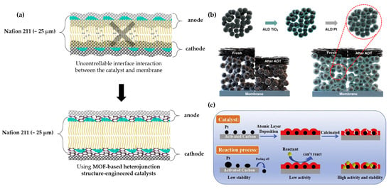
Figure 8.
Schematics of the following: (a) The proposed coating layer of ALD. (b) The mechanism of how the ALD is coated on the substrate conformally, which enhances the stability of the coating. Reprinted with permission from ref. [18]: Copyright 2024, ACS Sustainable Chemistry & Engineering. (c) The behavior of the catalyst particles in ALD. Reprinted with permission from ref. [41]: Copyright 2019, Catalysis Communications.
3.2. P-MEA System Fabrication
In contrast to the standard MEA system, few research efforts have been made to integrate both techniques for large-area applications in solar hydrogen production. In solar-to-hydrogen (STH) production with the MEA system, it can be mainly categorized into three types as follows:
- Integrated photovoltaic membrane electrode assembly (PV-MEA);
- Tandem photoelectrochemical membrane electrode assembly (PEC-MEA);
- Window-induced photocatalytic membrane electrode assembly (P-MEA).
While PV-MEA and PEC-MEA have been increasingly studied in recent decades, solar PV-MEA has become the most mature technology for generating renewable hydrogen [43]. For further improvement in STH efficiency, researchers have developed a system that comprises a PEC module using PV-MEA to achieve excellent efficiency and stability in STH yield. Following the hypotheses, T. Kistler et al. introduced a combined MEA-PEC-PV technique for solar water splitting. To access light through the system, they chose machined polymethylmethacrylate (PMMA) for the endplates, which is a tough, translucent, and chemically and mechanically resistant plastic, as described in Figure 9. As the endplates are insulators, an additional conductive tantalum foil was used for a flow field from channel reactants to the active sites and to remove products, while providing current collection for catalyst support. Lined patterning maximized the amount of light passing through the system. In the study, a non-transparent catalyst layer with electrocatalysts was used. An additional photovoltaic (PV) cell was attached to the device for incoming photo-adsorption. Although the photocatalytic efficiency can be maintained, the prolonged exposure of PV to the liquid electrolyte poses a challenge for this type of architectural device design. Conversely, PV cell corrosion severely affects the efficiency over extended operation, compromising the durability of the integrated system [44]. Moreover, the use of additional layers and coatings could obstruct light through the system components, thus requiring alternative catalyst layers to minimize light obstruction.
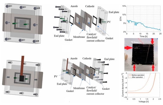
Figure 9.
Transparent PMMA endplate design of an integrated PV-MEA system. Reprinted with unrestricted permission from ref. [44]: Copyright 2019, Journal of The Electrochemical Society.
On the other hand, the operando characteristic measurement of the MEA system presents a novel, favorable design insight for the MEA system to operate under light illumination [45]. The MEA system features windows on the endplate for detecting incident rays as they pass through the catalyst layers. As shown in Figure 10a, the advanced integrated MEA system with a window holds promise for the MEA system to operate effectively for light absorption. J. Ampurdanes et al. customized the MEA system, which is convenient for operando XAS measurements [16]. The materials used for the stacks are carefully selected to allow an X-ray beam to pass through the system. This is achieved by replacing the insulating PTFE plate with Kapton film and modifying the aluminum endplates to include a window, as shown in Figure 10b. These studies provide an ideal design for the MEA system to operate under light absorption, as the standard MEA system faces significant challenges, particularly technological challenges such as high cost and poor durability [46]. As the current standard MEA system for hydrogen production remains uncompetitive to conventional combustion engine technology, the 2025 technology target set by the U.S. Department of Energy (DOE) has become a matter of concern [1]. To obtain a current density greater than 0.3 A cm−2 at 0.8 V, an external force would be required to maintain operation over 30,000 cycles. As solar energy is the most abundant, sustainable, and renewable source, it is favorable to utilize it as an external force for MEA system operation [46,47]. Thus, it is crucial to modify the alternative P-MEA system rather than using the standard MEA system to achieve the targets by operating the MEA hydrogen production under light absorption. The advanced integrated PV-MEA significantly yields better performance; however, due to additional stacks, the durability of the system steadily decreased over time. Thus, it is important to avoid complex and intricate interface interactions. In this regard, upgrading MEA fabrication to light-responsive system compartments would be promising for the entire hydrogen production from MEA-based water electrolysis. Following the concept of the operando measurements of MEA, adapting the window-induced light passage through the MEA system would be promising. The advanced system compartment designs include both-side transparent designs and one-side transparent designs, with the application of photocatalytic electrode materials in membrane electrode assembly (MEA), which is a P-MEA system.
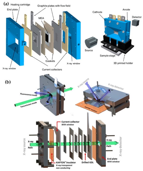
Figure 10.
MEA system design with windows in endplates. (a) An operando measurement for X-ray windows in the front and back endplates for beam transmission through the whole stack. Reprinted with unrestricted permission from ref. [45]: Copyright 2021, Journal of Physics: Condensed Matter. (b) MEA system with Kapton windows for the investigation of catalytic materials through the transmission/fluorescence mode of XAS measurement. Reprinted with unrestricted permission from ref. [16]: Copyright 2019, Catalysis Today.
In Table 4, possible fact-by-fact breakdowns are presented for why the all-in-one P-MEA system will offer significant advancements over photoelectrochemical (PEC) cells, which utilize the same light energy source for water electrolysis.

Table 4.
Comparative characteristics of P-MEA system vs. PEC cells.
In the P-MEA system, the direct solid-state interfaces between the photocatalysts and the membranes facilitate efficient charge transfer and minimize recombination losses. [48,49]. As mentioned before, engineered membranes within MEAs provide selective pathways for proton (H+) and oxygen (O2) transport, ensuring optimal ionic balance and enhancing overall reaction kinetics [50,51]. The immobilization of photocatalysts within the solid-state architecture of P-MEAs not only enhances mechanical stability but also protects against photocorrosion, thereby extending the operational lifespan of the system. Furthermore, the compact and modular design of MEAs allows for scalable implementation, a notable advantage over the often bulky and complex PEC setups [52,53,54]. Optimized thin-film geometries in P-MEAs ensure efficient light harvesting, leading to higher quantum efficiencies [55,56,57]. Collectively, these attributes underscore the superior performance and practical applicability of the P-MEA system in hydrogen production. Moreover, the performance efficiency, especially in terms of voltage, obtained at selected current densities is compared with that of traditional MEA water electrolysis and the integrated P-MEA (integrated PEC/PV-MEA) method in Table 5 [44,58,59,60,61,62,63]. For comprehensive and effective visualization, schematics describing the type and design of PV-MEA, PEC-MEA, and integrated P-MEA are shown in Figure 11. It is important to note that integrated P-MEA can provide a compact system design and membrane gas separation, but the STH lifetime remains very device-dependent, such as with regard to the light source, catalysts, and MEA fabrication design.

Table 5.
Comparison of hydrogen production performance across traditional MEA water electrolysis, PEC, and integrated P-MEA.
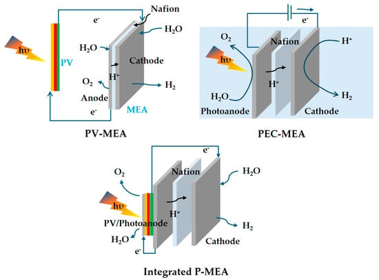
Figure 11.
Schematic representing MEA water electrolysis concepts under light absorption.
The comparative results highlight that while conventional MEA water electrolysis remains the benchmark for high current density and efficiency (1 A.cm−2 at 1.8 V, ), the evolution of photo-driven MEA architectures, particularly the integrated P-MEA system, marks an important step toward fully integrated solar hydrogen generation. Integrated P-MEAs, employing triple-junction Ga-based photon absorbers with wire-connected PEC configurations, achieved a respectable photon conversion efficiency of ~48.2% at an operating voltage of ~1 V. This demonstrates the feasibility of integrating the photo-absorbing system with the electrochemical functionalities through single-membrane assembly. Although the current densities (~50 mA.cm−2) are still far below those of conventional MEA water electrolysis, the bias voltage is reduced. Such systems prove that efficient solar-to-hydrogen conversion and effective separation can coexist in a compact device design. We believe that this helps researchers understand the current challenges of MEA water electrolysis and the need for the further development of P-MEA.
4. Conclusions and Future Perspectives
In this review, we discussed the current challenges in the standard MEA system and proposed essential strategies by introducing an all-in-one P-MEA. We then described the P-MEA system, which allows light to pass through the window and be absorbed by the ideal P-MEA, inspired by the concept of the operando characterization of MEA with windows in all MEA system components. Additionally, we suggested the suitable ALD technique for P-MEA, focusing on creating a conformal interface between the membrane and the CL while preserving the porous structure of the catalysts, which offers highly active sites for easier mass transport and better interface interaction. Furthermore, we explained the benefits of morphology-controlled catalyst structures in enhancing the feasibility of a P-MEA system’s hydrogen production. A light-driven P-MEA system for hydrogen production can be further developed with the following:
- i.
- Improved stability of light absorber and reduced bias overpotential;
- ii.
- Scalable fabrication system design;
- iii.
- Membrane-catalyst interface engineering to minimize resistive losses and enhance mass transport.
Several approaches can be adapted into P-MEA system development. The integration of tandem perovskite or III–V absorbers, earth-abundant catalysts, and light absorption operation modes will further boost efficiency while maintaining stability. Furthermore, careful selection of MEA deposition methods could highly improve the membrane–catalyst interface and avoid surface/interface peeling and fouling. Controlling the catalyst structure with a well-organized morphology and geometric structure is also necessary to prevent agglomeration and mass transport congestion. Last but not least, the band modulation of the catalyst through metal/non-metal doping and vacancy engineering is required for efficient light harvesting. As material and system engineering converge, the P-MEA concept could evolve into a practical, standalone solar hydrogen generation system, bridging the gap between laboratory-scale photoelectrochemical demonstrations and deployable solar energy technologies for sustainable green hydrogen production. However, ongoing interests and research could bridge the significant technology gap in the near future. Finally, we recommend exploring photocatalyst engineering not only for PEC but also for MEA operation under sustainable light energy sources.
Author Contributions
Supervision, conceptualization, validation, project administration, and funding acquisition: J.-H.Y.; original draft preparation, data preparation/collection, and editing: M.M.L.; reviewing and editing: B.-S.K., S.-M.L. and S.-H.A. All authors have read and agreed to the published version of the manuscript.
Funding
This work was supported by the Korea Institute of Energy Technology Evaluation and Planning (KETEP) and the Ministry of Trade, Industry & Energy (MOTIE) of the Republic of Korea (20224000000260) and the National Research Foundation of Korea (NRF) grant funded by the Korean government (MSIT) (RS-2024-00333809).
Institutional Review Board Statement
Not applicable.
Informed Consent Statement
Not applicable.
Data Availability Statement
No new data were created or analyzed in this study.
Acknowledgments
This work was supported by the Korea Institute of Energy Technology Evaluation and Planning (KETEP) and the Ministry of Trade, Industry & Energy (MOTIE) of the Republic of Korea (20224000000260) and the National Research Foundation of Korea (NRF) grant funded by the Korean government (MSIT) (RS-2024-00333809).
Conflicts of Interest
The authors declare no conflicts of interest.
References
- Hammi, Z.; Labjar, N.; Dalimi, M.; El Hamdouni, Y.; Lotfi, E.M.; El Hajjaji, S. Green hydrogen: A holistic review covering life cycle assessment, environmental impacts, and color analysis. Int. J. Hydrogen Energy 2024, 80, 1030–1045. [Google Scholar] [CrossRef]
- Jaradat, M.; Almashaileh, S.; Bendea, C.; Juaidi, A.; Bendea, G.; Bungau, T. Green Hydrogen in Focus: A Review of Production Technologies, Policy Impact, and Market Developments. Energies 2024, 17, 3992. [Google Scholar] [CrossRef]
- Sambasivam, B.; Sarma, R.N. India’s National Green Hydrogen Mission: An analysis of the strategies, policies for net-zero emissions and sustainability. Environ. Res. Energy 2024, 1, 045015. [Google Scholar] [CrossRef]
- Koivunen, T.; Hirvijoki, E. Effect of investment cost on technology preference in a flexible, low-carbon Finnish power system. Nucl. Eng. Des. 2024, 417, 112854. [Google Scholar] [CrossRef]
- Hyvönen, J.; Koivunen, T.; Syri, S. Possible bottlenecks in clean energy transitions: Overview and modelled effects–Case Finland. J. Clean. Prod. 2023, 410, 137317. [Google Scholar] [CrossRef]
- Durakovic, G.; Zhang, H.; Knudsen, B.R.; Tomasgard, A.; del Granado, P.C. Decarbonizing the European energy system in the absence of Russian gas: Hydrogen uptake and carbon capture developments in the power, heat and industry sectors. J. Clean. Prod. 2024, 435, 140473. [Google Scholar] [CrossRef]
- Muhammed, N.S.; Gbadamosi, A.O.; Epelle, E.I.; Abdulrasheed, A.A.; Haq, B.; Patil, S.; Al-Shehri, D.; Kamal, M.S. Hydrogen production, transportation, utilization, and storage: Recent advances towards sustainable energy. J. Energy Storage 2023, 73, 109207. [Google Scholar] [CrossRef]
- Nocera, D.G. The artificial leaf. Acc. Chem. Res. 2012, 45, 767–776. [Google Scholar] [CrossRef]
- Jin, W.; Shin, C.; Lim, S.; Lee, K.; Yu, J.M.; Seo, K.; Jang, J.-W. Natural leaf-inspired solar water splitting system. Appl. Catal. B Environ. 2023, 322, 122086. [Google Scholar] [CrossRef]
- Wang, Y.; Suzuki, H.; Xie, J.; Tomita, O.; Martin, D.J.; Higashi, M.; Kong, D.; Abe, R.; Tang, J. Mimicking Natural Photosynthesis: Solar to Renewable H2 Fuel Synthesis by Z-Scheme Water Splitting Systems. ACS Chem. Rev. 2018, 118, 5201–5241. [Google Scholar] [CrossRef]
- Mo, S.; Du, L.; Huang, Z.; Chen, J.; Zhou, Y.; Wu, P.; Meng, L.; Wang, N.; Xing, L.; Zhao, M.; et al. Recent Advances on PEM Fuel Cells: From Key Materials to Membrane Electrode Assembly. Electrochem. Energy Rev. 2023, 6, 28. [Google Scholar] [CrossRef]
- Segovia-Hernández, J.G.; Hernández, S.; Cossío-Vargas, E.; Juarez-García, M.; Sánchez-Ramírez, E. Green hydrogen production for sustainable development: A critical examination of barriers and strategic opportunities. RSC Sustain. 2024, 3, 134–157. [Google Scholar] [CrossRef]
- Galletti, A.; Pasimeni, F.; Melideo, D.; Desideri, U.; Alkemade, F. Learning in green hydrogen production: Insights from a novel European dataset. Int. J. Hydrogen Energy 2025, 148, 149812. [Google Scholar] [CrossRef]
- Siegmund, D.; Metz, S.; Peinecke, V.; Warner, T.E.; Cremers, C.; Grevé, A.; Smolinka, T.; Segets, D.; Apfel, U.-P. Crossing the Valley of Death: From Fundamental to Applied Research in Electrolysis. JACS Au 2021, 1, 527–535. [Google Scholar] [CrossRef] [PubMed]
- Lee, J.K.; Seo, J.H.; Lim, J.; Park, S.; Jang, H.W. Best Practices in Membrane Electrode Assembly for Water Electrolysis. ACS Mater. Lett. 2024, 6, 2757–2786. [Google Scholar] [CrossRef]
- Ampurdanés, J.; Chourashiya, M.; Urakawa, A. Cobalt oxide-based materials as non-PGM catalyst for HER in PEM electrolysis and in situ XAS characterization of its functional state. Catal. Today 2019, 336, 161–168. [Google Scholar] [CrossRef]
- Corrales-Sánchez, T.; Ampurdanés, J.; Urakawa, A. MoS2-based materials as alternative cathode catalyst for PEM electrolysis. Int. J. Hydrogen Energy 2014, 39, 20837–20843. [Google Scholar] [CrossRef]
- Shim, J.W.; Koo, J.; Yoo, S.J.; Shim, J.H. Exceptionally Stable Polymer Electrolyte Membrane Fuel Cells Enabled by One-Pot Sequential Atomic Layer Deposition of Titania and Platinum. ACS Sustain. Chem. Eng. 2024, 12, 15634–15642. [Google Scholar] [CrossRef]
- Liang, H.; Su, H.; Pollet, B.G.; Pasupathi, S. Development of membrane electrode assembly for high temperature proton exchange membrane fuel cell by catalyst coating membrane method. J. Power Sources 2015, 288, 121–127. [Google Scholar] [CrossRef]
- Fouzaï, I.; Gentil, S.; Bassetto, V.C.; Silva, W.O.; Maher, R.; Girault, H.H. Catalytic layer-membrane electrode assembly methods for optimum triple phase boundaries and fuel cell performances. RSC J. Mater. Chem. A 2021, 9, 11096–11123. [Google Scholar] [CrossRef]
- Nishioka, S.; Osterloh, F.E.; Wang, X.; Mallouk, T.E.; Maeda, K. Photocatalytic water splitting. Nat. Rev. Methods Prim. 2023, 3, 42. [Google Scholar] [CrossRef]
- Ma, Y.; Lin, L.; Takata, T.; Hisatomi, T.; Domen, K. A perspective on two pathways of photocatalytic water splitting and their practical application systems. Phys. Chem. Chem. Phys. 2023, 25, 6586–6601. [Google Scholar] [CrossRef]
- Zhang, J.; Chen, H.; Duan, X.; Sun, H.; Wang, S. Photothermal catalysis: From fundamentals to practical applications. Mater. Today 2023, 68, 234–253. [Google Scholar] [CrossRef]
- Li, Q.; Zhang, L.; Liu, J.; Zhou, J.; Jiao, Y.; Xiao, X.; Zhao, C.; Zhou, Y.; Ye, S.; Jiang, B.; et al. Porous Carbon Nitride Thin Strip: Precise Carbon Doping Regulating Delocalized π-Electron Induces Elevated Photocatalytic Hydrogen Evolution. Small 2021, 17, 2006622. [Google Scholar] [CrossRef]
- Li, Q.; Zhao, S.; Jiang, B.; Jaroniec, M.; Zhang, L. Engineering defects in graphitic carbon nitride photocatalysts. Mater. Today 2024, 80, 886–904. [Google Scholar] [CrossRef]
- Ha, M.N.; Lu, G.; Liu, Z.; Wang, L.; Zhao, Z. 3DOM-LaSrCoFeO6-: δ as a highly active catalyst for the thermal and photothermal reduction of CO2 with H2O to CH4. J. Mater. Chem. A 2016, 4, 13155–13165. [Google Scholar] [CrossRef]
- Grand, J.; Auguié, B.; Le Ru, E.C. Combined Extinction and Absorption UV-Visible Spectroscopy as a Method for Revealing Shape Imperfections of Metallic Nanoparticles. Anal. Chem. 2019, 91, 14639–14648. [Google Scholar] [CrossRef] [PubMed]
- Zhou, T.; Zhang, J.; Yang, S.; Jin, J.; Wang, B.; Li, G.T. The Oxygen Reduction Performance of Pt Supported on the Hybrid of Porous Carbon Nanofibers and Carbon Black. Materials 2022, 15, 4560. [Google Scholar] [CrossRef]
- Binninger, T.; Fabbri, E.; Kötz, R.; Schmidt, T.J. Determination of the Electrochemically Active Surface Area of Metal-Oxide Supported Platinum Catalyst. J. Electrochem. Soc. 2014, 161, H121–H128. [Google Scholar] [CrossRef]
- Dix, S.T.; Lu, S.; Linic, S. Critical Practices in Rigorously Assessing the Inherent Activity of Nanoparticle Electrocatalysts. ACS Catal. 2020, 10, 10735–10741. [Google Scholar] [CrossRef]
- Lian, M.M.; Lee, S.-M.; Ahn, S.-H.; Kim, B.-S.; Yun, J.-H. Sulfur Vacancy and V-Doped CoP-Modulated 3D Zr-MOF (UiO-66-NH2)/2D MoS2 Interface Restructuring for Efficient and Durable Hydrogen Evolution Reaction. ACS Energy Fuels 2025, 39, 16985–16993. [Google Scholar] [CrossRef]
- Suter, T.A.M.; Smith, K.; Hack, J.; Rasha, L.; Rana, Z.; Angel, G.M.A.; Shearing, P.R.; Miller, T.S.; Brett, D.J.L. Engineering Catalyst Layers for Next-Generation Polymer Electrolyte Fuel Cells: A Review of Design, Materials, and Methods. Adv. Energy Mater. 2021, 11, 2101025. [Google Scholar] [CrossRef]
- Wan, L.; Pang, M.; Le, J.; Xu, Z.; Zhou, H.; Xu, Q.; Wang, B. Oriented intergrowth of the catalyst layer in membrane electrode assembly for alkaline water electrolysis. Nat. Commun. 2022, 13, 7956. [Google Scholar] [CrossRef]
- Maiyalagan, T.; Pasupathi, S. Components for PEM fuel cells: An overview. Mater. Sci. Forum 2010, 657, 143–189. [Google Scholar] [CrossRef]
- Şanlı, L.I.; Yarar, B.; Bayram, V.; Gürsel, S.A. Electrosprayed catalyst layers based on graphene–carbon black hybrids for the next-generation fuel cell electrodes. J. Mater. Sci. 2017, 52, 2091–2102. [Google Scholar] [CrossRef]
- Fouzai, I.; Radaoui, M.; Díaz-Abad, S.; Rodrigo, M.A.; Lobato, J. Electrospray Deposition of Catalyst Layers with Ultralow Pt Loading for Cost-Effective H2 Production by SO2 Electrolysis. ACS Appl. Energy Mater. 2022, 5, 2138–2149. [Google Scholar] [CrossRef] [PubMed]
- Conde, J.J.; Ferreira-Aparicio, P.; Chaparro, A.M. Electrospray Deposition: A Breakthrough Technique for Proton Exchange Membrane Fuel Cell Catalyst Layer Fabrication. ACS Appl. Energy Mater. 2021, 4, 7394–7404. [Google Scholar] [CrossRef]
- Kim, G.; Eom, K.; Kim, M.; Yoo, S.J.; Jang, J.H.; Kim, H.-J.; Cho, E. Design of an Advanced Membrane Electrode Assembly Employing a Double-Layered Cathode for a PEM Fuel Cell. ACS Appl. Mater. Interfaces 2015, 7, 27581–27585. [Google Scholar] [CrossRef]
- Aoyama, Y.; Suzuki, K.; Tabe, Y.; Chikahisa, T.; Tanuma, T. Water Transport and PEFC Performance with Different Interface Structure between Micro-Porous Layer and Catalyst Layer. J. Electrochem. Soc. 2016, 163, F359–F366. [Google Scholar] [CrossRef]
- Song, Z.; Banis, M.N.; Liu, H.; Zhang, L.; Zhao, Y.; Li, J.; Doyle-Davis, K.; Li, R.; Knights, S.; Ye, S.; et al. Ultralow Loading and High-Performing Pt Catalyst for a Polymer Electrolyte Membrane Fuel Cell Anode Achieved by Atomic Layer Deposition. ACS Catal. 2019, 9, 5365–5374. [Google Scholar] [CrossRef]
- Lin, W.; Chen, H.; Li, J.; Chen, K.; Lu, X.; Ouyang, P.; Fu, J. Enhanced stability of Pt/C by the atomic layer deposition of porous MOx for the decarboxylation of oleic acid. Catal. Commun. 2019, 123, 59–63. [Google Scholar] [CrossRef]
- Yang, B.; Xiang, Z. Nanostructure Engineering of Cathode Layers in Proton Exchange Membrane Fuel Cells: From Catalysts to Membrane Electrode Assembly. ACS Nano 2024, 18, 11598–11630. [Google Scholar] [CrossRef] [PubMed]
- Turan, B.; Becker, J.-P.; Urbain, F.; Finger, F.; Rau, U.; Haas, S. Upscaling of integrated photoelectrochemical water-splitting devices to large areas. Nat. Commun. 2016, 7, 12681. [Google Scholar] [CrossRef] [PubMed]
- Kistler, T.A.; Larson, D.; Walczak, K.; Agbo, P.; Sharp, I.D.; Weber, A.Z.; Danilovic, N. Integrated Membrane-Electrode-Assembly Photoelectrochemical Cell under Various Feed Conditions for Solar Water Splitting. J. Electrochem. Soc. 2019, 166, H3020–H3028. [Google Scholar] [CrossRef]
- Leach, A.S.; Hack, J.; Amboage, M.; Diaz-Moreno, S.; Huang, H.; Cullen, P.L.; Wilding, M.; Magliocca, E.; Miller, T.; A Howard, C.; et al. A novel fuel cell design for operando energy-dispersive x-ray absorption measurements. J. Phys. Condens. Matter. 2021, 33, 314002. [Google Scholar] [CrossRef]
- Tölle, P.; Köhler, C.; Marschall, R.; Sharifi, M.; Wark, M.; Frauenheim, T. Proton transport in functionalised additives for PEM fuel cells: Contributions from atomistic simulations. Chem. Soc. Rev. 2012, 41, 5143–5159. [Google Scholar] [CrossRef]
- Wilhelm, M.; Jeske, M.; Marschall, R.; Cavalcanti, W.L.; Tölle, P.; Köhler, C.; Koch, D.; Frauenheim, T.; Grathwohl, G.; Caro, J.; et al. New proton conducting hybrid membranes for HT-PEMFC systems based on polysiloxanes and SO3H-functionalized mesoporous Si-MCM-41 particles. J. Membr. Sci. 2008, 316, 164–175. [Google Scholar] [CrossRef]
- Wijayatha, K. Photoelectrochemical cells for hydrogen generation. Funct. Mater. Sustain. Energy Appl. 2012, 146e, 91–145. [Google Scholar] [CrossRef]
- Liu, B.; Wang, S.; Zhang, G.; Gong, Z.; Wu, B.; Wang, T.; Gong, J. Tandem cells for unbiased photoelectrochemical water splitting. RSC Chem. Soc. Rev. 2023, 52, 4644–4671. [Google Scholar] [CrossRef]
- Vinodh, R.; Palanivel, T.; Kalanur, S.S.; Pollet, B.G. Recent advancements in catalyst coated membranes for water electrolysis: A critical review. RSC Energy Adv. 2024, 3, 1144–1166. [Google Scholar] [CrossRef]
- Wang, S.; Li, Y.; Wang, X.; Zi, G.; Zhou, C.; Liu, B.; Liu, G.; Wang, L.; Huang, W. One-step supramolecular preorganization constructed crinkly graphitic carbon nitride nanosheets with enhanced photocatalytic activity. J. Mater. Sci. Technol. 2022, 104, 155–162. [Google Scholar] [CrossRef]
- da Costa, G.P.; Garcia, D.M.; Van Nguyen, T.H.; Lacharmoise, P.; Simão, C.D. Advancements in printed components for proton exchange membrane fuel cells: A comprehensive review. Int. J. Hydrogen Energy 2024, 69, 710–728. [Google Scholar] [CrossRef]
- Vilanova, A.; Dias, P.; Lopes, T.; Mendes, A. The route for commercial photoelectrochemical water splitting: A review of large-area devices and key upscaling challenges. RSC Chem. Soc. Rev. 2024, 53, 2388–2434. [Google Scholar] [CrossRef] [PubMed]
- Mani, P.; Shenoy, S.; Sagayaraj, P.J.J.; Agamendran, N.; Son, S.; Bernaurdshaw, N.; Kim, H.-I.; Sekar, K. Scaling up of photocatalytic systems for large-scale hydrogen generation. Appl. Phys. Rev. 2025, 12, 011303. [Google Scholar] [CrossRef]
- Haferkamp, S.; Haase, W.; Pascal, A.A.; van Amerongen, H.; Kirchhoff, H. Efficient light harvesting by photosystem II requires an optimized protein packing density in grana thylakoids. J. Biol. Chem. 2010, 285, 17020–17028. [Google Scholar] [CrossRef]
- Eggimann, H.J.; Patel, J.B.; Johnston, M.B.; Herz, L.M. Efficient energy transfer mitigates parasitic light absorption in molecular charge-extraction layers for perovskite solar cells. Nat. Commun. 2020, 11, 5525. [Google Scholar] [CrossRef]
- Shen, X.; Wang, Z.; Wangyang, P.; Zhou, H. Light harvesting in thin film solar cells via designing nanostructured geometries. Opt. Commun. 2023, 545, 129624. [Google Scholar] [CrossRef]
- Li, J.; Yuan, H.; Zhang, W.; Jin, B.; Feng, Q.; Huang, J.; Jiao, Z. Advances in Z-scheme semiconductor photocatalysts for the photoelectrochemical applications: A review. Carbon Energy 2022, 4, 294–331. [Google Scholar] [CrossRef]
- Azam, A.M.I.N.; Li, N.K.; Zulkefli, N.N.; Masdar, M.S.; Majlan, E.H.; Baharuddin, N.A.; Zainoodin, A.M.; Yunus, R.M.; Shamsul, N.S.; Husaini, T.; et al. Parametric Study and Electrocatalyst of Polymer Electrolyte Membrane (PEM) Electrolysis Performance. Polymers 2023, 15, 560. [Google Scholar] [CrossRef]
- Wang, C.R.; Stansberry, J.M.; Mukundan, R.; Chang, H.-M.J.; Kulkarni, D.; Park, A.M.; Plymill, A.B.; Firas, N.M.; Liu, C.P.; Lang, J.T.; et al. Proton Exchange Membrane (PEM) Water Electrolysis: Cell-Level Considerations for Gigawatt-Scale Deployment. ACS Chem. Rev. 2025, 125, 1257–1302. [Google Scholar] [CrossRef]
- El-Shafie, M. Hydrogen production by water electrolysis technologies: A review. Results Eng. 2023, 20, 400006. [Google Scholar] [CrossRef]
- Amano, F.; Tsushiro, K. Proton exchange membrane photoelectrochemical cell for water splitting under vapor feeding. Energy Mater. 2024, 4, 77. [Google Scholar] [CrossRef]
- Patel, M.; Cattry, A.; Jonin, M.; Tembhurne, S.; Haussener, S. Reversible photo-electrochemical device for solar hydrogen and power generation. Cell Rep. Phys. Sci. 2024, 5, 101984. [Google Scholar] [CrossRef]
- Chatenet, M.; Pollet, B.G.; Dekel, D.R.; Dionigi, F.; Deseure, J.; Millet, P.; Braatz, R.D.; Bazant, M.Z.; Eikerling, M.; Staffell, I.; et al. Water electrolysis: From textbook knowledge to the latest scientific strategies and industrial developments. RSC Chem. Soc. Rev. 2022, 51, 4583–4762. [Google Scholar] [CrossRef]
- Wang, J.; Branco, B.; Remmerswaal, W.H.M.; Hu, S.; Schipper, N.R.M.; Zardetto, V.; Bellini, L.; Daub, N.; Wienk, M.M.; Wakamiya, A.; et al. Performance and stability analysis of all-perovskite tandem photovoltaics in light-driven electrochemical water splitting. Nat. Commun. 2025, 16, 174. [Google Scholar] [CrossRef]
Disclaimer/Publisher’s Note: The statements, opinions and data contained in all publications are solely those of the individual author(s) and contributor(s) and not of MDPI and/or the editor(s). MDPI and/or the editor(s) disclaim responsibility for any injury to people or property resulting from any ideas, methods, instructions or products referred to in the content. |
© 2025 by the authors. Licensee MDPI, Basel, Switzerland. This article is an open access article distributed under the terms and conditions of the Creative Commons Attribution (CC BY) license (https://creativecommons.org/licenses/by/4.0/).