Abstract
On 6 February 2023, two consecutive earthquakes, with magnitudes of 7.8 and 7.7 (Mw), struck Kahramanmaras Province in the Mediterranean region of Turkey. A thorough evaluation of post-seismic damage to underground structures is critically important for ensuring both structural safety and operational serviceability. Focusing on the Erkenek Tunnel, this study provides a systematic investigation to assess the impact of the devastating Kahramanmaras earthquakes on highway tunnels. The tunnel sustained significant damage, primarily concentrated in its inner lining structures, and as a result, its left tube was shut down for service. Based on the in situ observations, geological conditions, initial design documents and construction techniques, a numerical analysis was conducted to model critical tunnel sections and evaluate their structural stability. Considering both static loads and seismic forces, restoration design works, techniques and construction sequences are recommended for the damaged sections of the Erkenek Tunnel. As the earthquake damage sustained by underground structures is a rare case, the methodology and findings of this study regarding post-seismic tunnel inspections and rehabilitation designs shed light on the maintenance works of in-service tunnels in earthquake-prone zones.
1. Introduction
Straddling the continents of Asia and Europe, Turkey is predominantly located on the Anatolian Peninsula. Its diverse landscapes have been formed by a wide range of tectonic processes throughout geological history. This tectonic activity continues today, driven by the convergence of the African Plate with the Eurasian Plate, which propels the Anatolian Plate westward and southwestward along strike-slip faults [1]. The principal fault systems in Turkey are the North Anatolian Fault Zone (NAFZ) and the East Anatolian Fault Zone (EAFZ). The former shapes the current plate boundary of Eurasia near the Black Sea coast, while the latter forms part of the boundary of the North Arabian Plate in the southeast [2]. Turkey’s seismically active geology—characterized by recent faulting and folding, with ongoing orogenic processes—makes the country susceptible to frequent earthquakes of varying magnitudes [3]. More recently, two consecutive and powerful earthquakes occurred in Kahramanmaras Province, located in southern Turkey. On 6 February 2023, at 04:17 local time, the first intense earthquake (in the Pazarcik district, Kahramanmaras) with a magnitude of Mw 7.8 hit southern and central Turkey and northern and western Syria. It was followed by a second earthquake with a magnitude of Mw 7.7 (in Elbistan district, Kahramanmaras) at 13:24 local time the same day. The Pazarcik earthquake had an epicenter at 37.166° N; 37.032° E, approximately 34 km west of Gaziantep Province, near the Syrian border. The following Elbistan earthquake had an epicenter at 38.089° N; 37.239° E, situated about 95 km northeast of the former earthquake. The Pazarcik and Elbistan earthquakes had shallow focal depths of 8.6 and 7.0 km, respectively, and both shocks were caused by strike-slip faulting within the EAFZ. In the earthquake-stricken areas, a total of 45,756 aftershocks were recorded within the first year following the earthquakes [4]. The corresponding shakemaps of these earthquakes are given in Figure 1 [5,6].
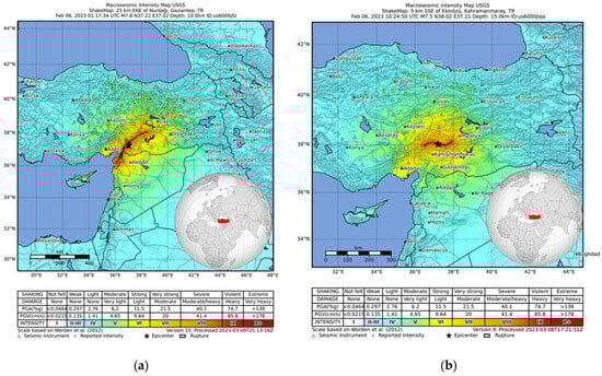
Figure 1.
Epicenter locations of the earthquakes: (a) Pazarcik earthquake; (b) Elbistan earthquake.
The deadliest earthquakes resulted in a total of 62,013 fatalities (53,537 in Turkey and 8476 in Syria) and injured more than 110,000 individuals according to the latest reports. Moreover, these destructive natural disasters wreaked havoc on both residential and non-residential buildings, as well as the main transportation infrastructure, including airports, roads, railways, bridges, and tunnels. Officials at Turkey’s Presidency of Strategy and Budget have estimated the total economic loss from the earthquakes to be at least $104 billion, equivalent to approximately 9% of the country’s 2023 GDP, thereby making this one of the most costly earthquakes in modern Turkish history [7].
Resilient transportation systems are essential for the prompt deployment of search and rescue teams and the uninterrupted delivery of medical supplies and logistical support to disaster-affected areas following earthquakes and other major natural disasters. Similarly to many countries worldwide, highway transportation is the most preferred mode in Turkey due to its door-to-door service, flexible travel schedules, accessibility to remote areas, and ease of integration with other transportation systems. Turkey currently has a highway network exceeding 70,000 km. To maintain the continuity of this network, 495 highway tunnels with a total length of 753 km have been constructed, primarily in response to the challenging geological and topographic conditions along certain routes. Within the framework of the emergency action plans, it is vital that the highway tunnels—whose initial construction costs are considerably high—provide safe, uninterrupted, and sustainable service during and after earthquakes or other major disasters. Yet, it should be noted that underground structures—particularly those passing through large active fault zones or crossing active faults—are highly vulnerable to seismic loads. An accurate and realistic post-seismic evaluation is necessary to ensure the safety of these underground structures; however, a research gap remains in this area within the literature. The historic Kahramanmaras-centered earthquakes resulted in serious damage to highway tunnels serving the earthquake-affected regions, leading to disruptions in road transportation. The Erkenek Tunnel is one of the seismically damaged highway tunnels affected by these destructive earthquakes. A field survey revealed extensive seismic damage exhibiting various patterns across its structural components. Within the scope of this study, earthquake-induced damage in the Erkenek Tunnel will first be determined along with damage patterns. Then, the tunnel will be modeled using computer-aided design software, and its structural safety will be evaluated under both static and seismic loading conditions. Based on the analysis of the damaged sections, a restorative design for a new tunnel lining is proposed with the aim of preventing future deterioration and providing safe and sustainable tunnel operation. Given its proximity to an active fault zone and the seismic challenges it has endured, the Erkenek Tunnel presents a compelling case study for evaluating the design considerations for both existing and future tunnels. Accordingly, this paper presents a pilot study that contributes to the improvement of seismic resilience and the extension of service life of highway tunnels.
2. Literature Review
To date, a wide range of research has focused on understanding the effects of earthquakes and seismic faulting on road tunnels. A preliminary analysis by Yao et al. (2024) revealed that the mechanisms of earthquake-induced tunnel damage were closely associated with old landslide masses, fractured zones, invert setup, and the direction of tunnel alignment [8]. Zhang et al. (2020) identified additional influencing factors, including earthquake parameters, structural forms, and geological conditions under earthquake forces [9]. Then, they further proposed restoration design criteria and methods, taking a case study of a tunnel subjected to an earthquake with a magnitude Mw 7.0 in 2016. Using a deep learning approach, Ansari et al. (2023) developed a seismic tunnel damage prediction model capable of determining damage indices, damage patterns, and mitigation measures for post-seismic scenarios [10]. The use of dynamic analysis tools has been shown to be highly effective in revealing the interaction between the dynamic response of the tunnel lining and the frequency content of ground motion, which sparks an amplification of the internal forces within the lining [11]. A computer-aided modeling also proved that the introduction of pseudo-static horizontal earthquake body forces into a single circular tunnel increased the peak horizontal displacements within the media and increased the degree of asymmetry in the stresses and distribution patterns [12].
Xin et al. (2024) reported that there is a clear distinction between fault-crossing and non-fault-crossing tunnels in terms of seismic damage classification [13]. The former experiences combined effects of intense fault displacement and seismic motion, leading to considerable transverse squeezing, shearing, and extensive spalling of the tunnel lining. In contrast, the latter is primarily affected by seismic motion, and unless subjected to strong high-energy pulses, secondary fault displacements are typically not triggered. Zhang et al. (2017) investigated the impact of fault location and thickness on the stability of surrounding rock masses [14]. They concluded that faults would not always lead to an increase in the compressive and tensile strength and deformation in rock masses. However, they could reduce displacement, plastic zone extent, and stresses in the surrounding rock and shotcrete lining. An increased fault thickness significantly raised the areas of the tensile stress and the plastic zone in a nonlinear way. Similarly, Zhao et al. (2025) stated that as fault width increases, the internal forces within the tunnel structure decrease [15]. Other parameters—including fault type, epicentral distance, earthquake magnitude, source depth, and rise time—also merit detailed investigation. Accordingly, Chen et al. (2024) addressed that oblique strike-slip and thrust faults exhibit higher stress intensities, which makes tunnels more susceptible to earthquake forces [16]. For strike-slip earthquakes in particular, shear and normal strains induced by fault displacement are primary causes of tunnel damage in both axial and lateral directions [17]. Earthquakes with a magnitude greater than Mw 6.5 have a significant impact on the stress response of tunnels, whereas source depth and rise time have relatively minor effects. Chen et al. (2023) examined the failure mechanism of a tunnel near fault zones from the viewpoints of dislocation failure and impact failure [18]. The former was found to be dominated by non-uniform dislocation displacement along the tunnel’s longitudinal axis, primarily controlled by the amount of dislocation. The latter, by contrast, was the result of crushing and inverse uplift within the tunnel cross-section, which is mainly related to pulse duration. In line with these findings, Du et al. (2025) suggested that initial damage caused by fault dislocation worsens subsequent tunnel damage under seismic action, and an increase in initial fault displacement and peak ground acceleration significantly aggravates lining damage [19].
Xia et al. (2022) evaluated the critical role of anti-dislocation deformation joints in tunnels passing through active faults [20]. They underlined that these joints substantially reduced both longitudinal and transverse lining strains within fault fracture zones. Anti-dislocation deformation joints were observed to effectively decrease internal forces and bending moments in the lining, thereby mitigating seismic damage in the lining. In another study, the incorporation of a 10–20 cm-thick seismic buffer layer was found to significantly reduce lining failures by limiting multi-directional lining displacements [21]. Considering the vulnerability of the vault bottom and vault areas near faults during strong earthquakes, Wang et al. (2024) recommended the utilization of steel-basalt hybrid fiber reinforced concrete for lining [22]. As an alternative to plain concrete, it exhibited an 11.2-fold increase in the minimum safety factor and demonstrated a markedly lower degree of structural damage.
3. Technical Background of the Erkenek Tunnel
The Erkenek tunnel is situated along the D-850 Malatya—Adiyaman State Highway, between the districts of Dogansehir (Malatya) and Golbasi (Adiyaman). It comprises two unidirectional twin tubes: the right tube is 1816 m long (from mileage K76 + 008 to K77 + 824), while the left tube measures 1846 m (from mileage K75 + 978 to K77 + 824).
Connecting the eastern part of Turkey with the Mediterranean region, this tunnel provides a crucial transportation link through the mountainous terrain of the Erkenek area. It ensures time and fuel savings, safety, sustainability, and efficient vehicular passage, particularly under harsh winter conditions. The tunnel structure consists of a primary (initial) lining, a secondary (final) lining, and a waterproofing system. The tunnel was constructed between the year 2011 and 2017, following the principles of the New Austrian Tunnelling Method (NATM). Each tunnel tube has a cross-sectional width of 10.60 m and a maximum height of 10.17 m. The road pavement is composed of a bituminous mixture with an overall thickness of 0.55 m.
The Erkenek Tunnel is located in close proximity to an active fault zone, with a straight-line distance of approximately 3000 m from its central alignment to the East Anatolian Fault Zone (EAFZ). In addition to its location within a major strike-slip fault zone, unanticipated soil conditions—resulting from insufficient preliminary geotechnical investigations and limited boring works—caused significant challenges during construction. These included mass wasting and ground subsidence in several tunnel sections and portals. After opening to service, the tunnel has been influenced by multiple faults exhibiting varying strikes and dip angles relative to its longitudinal axis. During the 6 February 2023 Pazarcik earthquake (Mw 7.8), whose epicenter was located approximately 70 km away, both tunnel tubes sustained severe structural damage. The subsequent Elbistan earthquake (Mw 7.7) further exacerbated the damage, amplifying pre-existing cracks and spalling within the tunnel linings and sidewalls. As a result, the left tube was permanently closed to traffic, while the right tube experienced temporary service disruptions.
4. Seismic Damage to the Erkenek Tunnel
Following the Kahramanmaras earthquakes, a comprehensive investigation was conducted to assess the extent of the damage in the Erkenek Tunnel. This process involved the collection of geotechnical investigation reports, geological condition assessments, approved design documents, and construction records. Subsequently, a field survey—similar in approach to that of the Structural Extreme Events Reconnaissance (StEER) Network—was carried out to identify and classify the various types of structural damage [23]. Previous studies have reported that the most common forms of earthquake-induced damage in tunnels include cracking of the lining, concrete spalling and collapse, shear failure of the lining, portal cracking, damage at construction joints, slope-induced collapses near portals, groundwater leakage, sidewall and invert deformation, tunnel floor heaving, and pavement damage [24,25]. Among these, lining cracks are the most frequently observed seismic damage type, typically categorized into four distinct patterns: longitudinal cracks, transverse cracks, inclined cracks, and enclosed (ring) cracks [9]. Based on this generally accepted classification, the earthquake-driven damages detected in the Erkenek Tunnel are categorized and summarized in Table 1, and their field pictures are given in Figure 2.

Table 1.
Damage descriptions.
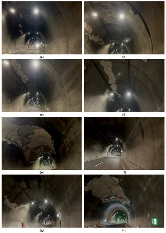
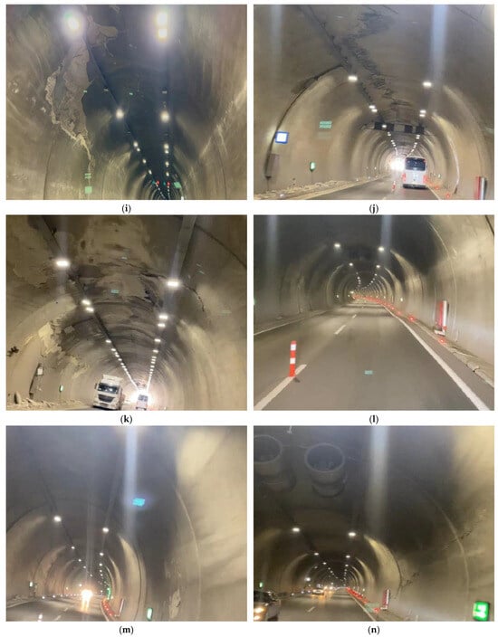
Figure 2.
On-site seismic damage investigation at relevant tunnel sections: (a–n).
It is well known that groundwater conditions can significantly affect degradation and lining stress in tunnels; however, no groundwater inflows or seasonal variations were documented prior to the earthquakes, nor were any detected afterward.
5. Back Analysis
Modeling post-seismic damage in tunnels through numerical simulations is a complex yet crucial task in tunneling and geotechnical engineering. It involves replicating how both the tunnel and surrounding ground behave after an earthquake, accounting for both immediate and residual damage. In this study, the current condition of each critical section of the Erkenek Tunnel was modeled using the Finite Element Method (FEM). It is one of the most common numerical analysis methods used in tunnel engineering due to its ability to incorporate stress anisotropy, material heterogeneity, complex boundary conditions, and various structural interactions. The analysis was conducted using PLAXIS 2D (CONNECT Edition V21). The soil/rock mass was discretized using 15-node triangular elements. The tunnel lining was modeled with plate elements, while interface elements were used to simulate the interaction between the tunnel lining and the surrounding ground. A plane strain model was employed, and local mesh refinement was carried out to ensure mesh convergence and accurately capture sharp stress variations in critical sections. The related deformation parameters representing displacements that emerged during tunnel construction were determined by back analysis. Within the scope of this study, the restoration of the inner (primary) lining structure was studied in detail.
The deformation parameters forming the basis of the restoration works are based on a set of assumptions and calculations. In the analytical models, the rock units were accepted as elasto-plastic materials according to the Hoek-Brown failure criterion, and the relevant strength and deformation parameters were determined from geological and geotechnical studies. According to the NATM classification, the tunnel sections currently fall under support classes B2–B3, C2, and C3, depending on the local ground conditions. The initial stresses around the excavation boundary are functions of the overburden depth and the elastic properties of the materials. The vertical stress along the tunnel boundary is generally proportional to the overburden depth [26]. In this respect, the geometry of the existing tunnel section was used to estimate the overburden pressure in this study. The coefficient of lateral earth pressure at rest, “K0”—defined as the ratio of the average horizontal stress to the vertical stress—was calculated using Equation (1) [27]. The calculated K0 values are given in Table 2.
where h is the overburden depth (m) and E is the elasticity modulus (GPa).
K0 = σh,av/σz = 0.33 + 9.50 × E × (0.001 + (1/h))
Table 2.
Determination of K0 values.
In sections with relatively poor ground conditions, the analyses were performed based on Equation (1), whereas in rock sections with greater overburden thickness, the scale developed by Hoek and Brown (Figure 3) was employed. Based on the overall calculations and approaches, the K0 value was taken as 0.5 throughout the tunnel.
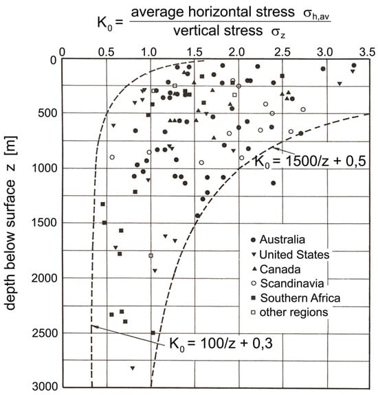
Figure 3.
Variation of K0 with depth. Reprinted from ref. [28].
To estimate the long-term in situ stress conditions that have affected the primary lining structure, the displacement values observed after the installation of the primary anchorage system were analyzed. Information compiled from previous engineering studies, calculation sections, and displacement values was gathered for this purpose. In order to model the long-term loading on the primary lining accurately, it is necessary to estimate the pressure exerted by the primary support system corresponding to the observed displacements. The simplest way to do this is to gradually reduce the modulus of elasticity of a fictitious material placed inside the tunnel. The displacements in the critical tunnel sections, along with the ratio of the reduced elastic modulus to the initial elastic modulus corresponding to these displacements, are given below in Table 3.
Table 3.
Critical tunnel sections.
The modeling stages of each tunnel section under static loading conditions are given in Figure 4. The initial stress state is given in Figure 4a, whereas the closest approximation of the primary support system pressure to actual field conditions is illustrated in Figure 4b. The final modeling scenario (Figure 4c) represents the case in which the primary lining is reconstructed under the assumption that the existing primary support elements have completely lost their functionality over the long term.
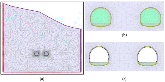
Figure 4.
Analysis stages of primary lining under static loading conditions. (a) Initial stress state; (b) Primary support system pressure; (c) Reconstruction of the primary lining.
Based on the existing tunnel support system and tunnel geometry, it was aimed to determine the deformation parameters representing the actual field conditions (Figure 5).
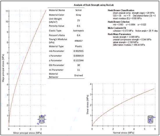
Figure 5.
Rock strength analysis of the tunnel at K76 + 950.
As a result of the back analysis (Figure 6 and Figure 7), the elasticity modulus at K76 + 950 was determined to be 537 MPa, corresponding to a deformation of approximately 40 cm. The cross-section of the inner lining structure of the tunnel in the C3 section at K76 + 950 is given without scale in Figure 8. The thickness of the reinforced primary lining is at least 65 cm, and the invert thickness is a minimum of 70 cm throughout the C3 NATM classification.
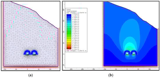
Figure 6.
Back-analysis model of the current situation at K76 + 950 by FEM; (a) Model setup, (b) Total displacement.
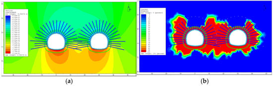
Figure 7.
(a) Vertical displacement; (b) Soil plastification in the current tunnel section.
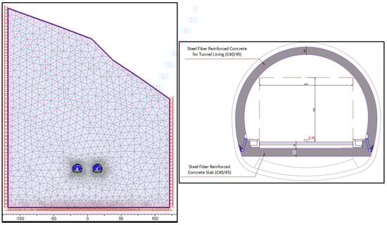
Figure 8.
FEM of the C3 tunnel excavation and support system.
The tunnel and surrounding ground were modeled with the FEM, and the displacements of the inner lining under static loading conditions were analyzed; the results are given in Figure 9a. The internal forces (axial force, bending moment, and shear force) acting on the tunnel primary lining and invert slab are presented in Figure 9b–d.
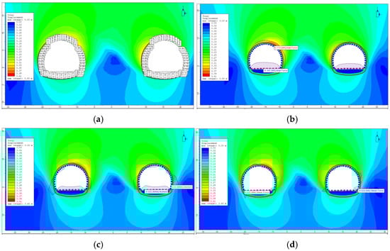
Figure 9.
C3 section. (a) Total displacement; (b) Axial force; (c) Bending moment; (d) Shear force.
According to the analysis given in Figure 10 and Table 4, the excavation and support systems indicate that the C3 rock class of the Erkenek Tunnel at K76 + 950 has sufficient capacity to satisfy the shear strength requirements under static loading conditions. However, it is planned to preserve the existing invert and construct a new reinforced concrete layer above it.
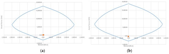
Figure 10.
C3 section under static loading conditions. (a) Lining; (b) Invert slab.
Table 4.
Analysis of the lining and invert slab in the C3 section under static loading conditions.
The strength analysis of the C2 rock class excavation at K76 + 200 is given in Figure 11. The scale-free section of the primary lining structure in the C2 tunnel section is drawn in Figure 12, where the lining thickness is 40 cm and the concrete slab thickness is 70 cm. Similarly to the previous section, the tunnel and surrounding ground were modeled with the FEM (Figure 12). Taking the static loading state into consideration, the tunnel displacements were calculated, and they are given in Figure 13a. The internal forces acting on this section are presented in Figure 13b–d.
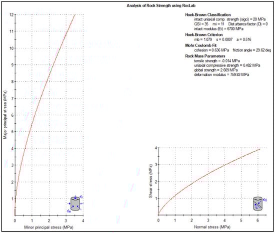
Figure 11.
Strength analysis of the C2 rock class excavation at K76 + 200.
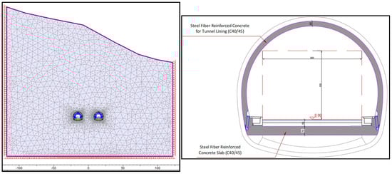
Figure 12.
FEM of the C2 tunnel excavation and support system.
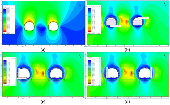
Figure 13.
C2 section. (a) Total displacement; (b) Axial force; (c) Bending moment; (d) Shear force.
As shown in Figure 14 and Table 5, the existing excavation (without the invert) and support systems recommend that the C2 rock class of the Erkenek Tunnel at K76 + 200 has adequate capacity to satisfy the shear strength requirements. While preserving the existing invert, it is planned to construct a new reinforced concrete layer above it. Furthermore, a joint structure should be constructed in a way that the base arch section will work together with the existing undamaged invert. In this way, the arched invert helps ensure that the internal forces remain within safe limits.
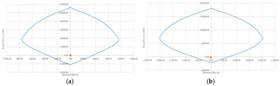
Figure 14.
C2 section under static loading conditions. (a) Lining; (b) Invert slab.
Table 5.
Analysis of the lining and invert slab in the C2 section under static loading conditions.
The same tunnel section (C2 rock class at K76 + 200) was also analyzed, considering the invert. The tunnel and surrounding ground were modeled by the FEM (Figure 15), and the resulting tunnel displacements are shown in Figure 16a. The internal forces on the primary lining are presented in Figure 16b–d.
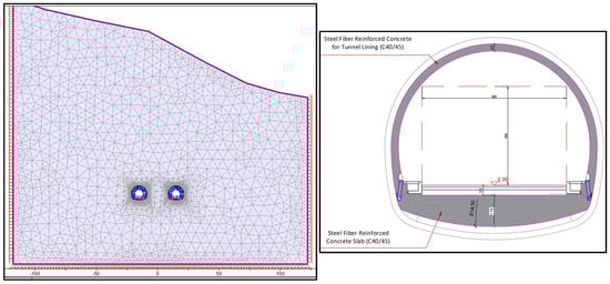
Figure 15.
FEM of the C2 tunnel excavation and support system (with invert).
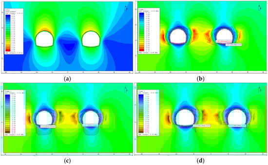
Figure 16.
C2 section (with invert). (a) Total displacement; (b) Axial force; (c) Bending moment; (d) Shear force.
As evidenced by Figure 17 and Table 6, the excavation and support system of the inverted arch demonstrates that the C2 rock class at K76 + 200 of the Erkenek Tunnel has sufficient capacity to satisfy the shear strength requirements under static loading conditions.
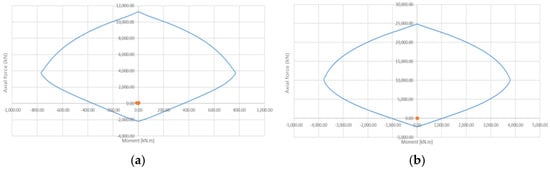
Figure 17.
C2 section (with invert) under static loading conditions. (a) Lining; (b) Invert slab.
Table 6.
Analysis of the lining and invert slab in the C2 section (with invert) under static loading conditions.
Similarly to previous critical sections, the tunnel and surrounding ground were modeled for the B3 tunnel lining at K77 + 200 according to rock strength analysis (Figure 18). An unscaled cross-section of the tunnel (Figure 19) shows that the reinforced lining has a uniform thickness of 40 cm, whereas the in situ invert lining reaches a maximum thickness of 115 cm. At the junction with the invert, the lining thickness is approximately 40 cm. The calculated tunnel displacements are illustrated in Figure 20a, and the internal forces on the tunnel primary lining are presented in Figure 20b–d.
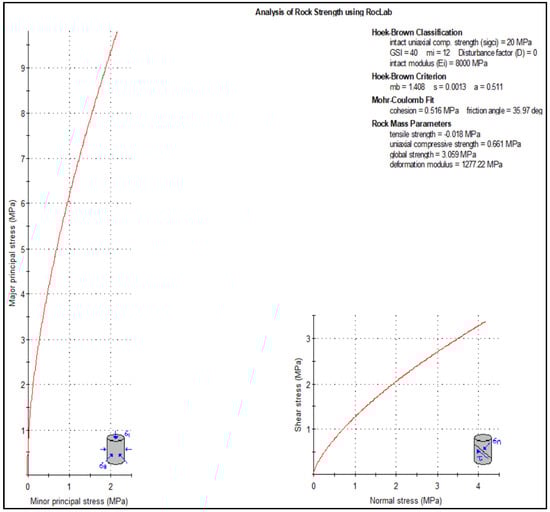
Figure 18.
Strength analysis of the B3 rock class excavation at K77 + 200.
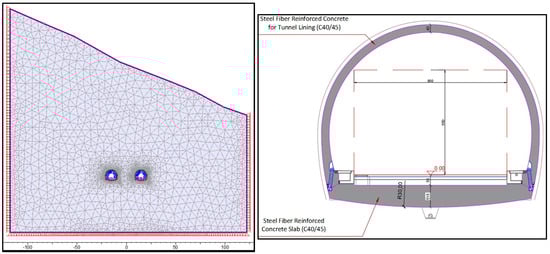
Figure 19.
FEM of the B3 tunnel excavation and support system (with invert).
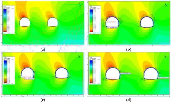
Figure 20.
B3 section (with invert). (a) Total displacement; (b) Axial force; (c) Bending moment; (d) Shear force.
The overall results shown in Figure 21 and Table 7 indicate that the inverted arch excavation and support system designed for the B3 rock class at K77 + 200 of the Erkenek Tunnel is capable of satisfying the shear strength requirements. Overall, the numerical model results show high tensile stresses and curvature in areas where cracks were observed in the field. Although explicit cracking was not modeled, these stress concentrations align with the damage patterns observed during post-earthquake inspections, supporting the model’s predictive capability.
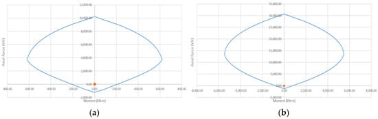
Figure 21.
B3 section (with invert) under static loading conditions. (a) Lining; (b) Invert slab.
Table 7.
Analysis of the lining and invert slab in the B3 section (with invert) under static loading conditions.
It is important to note that the current back analysis primarily addressed the immediate and residual deformation state of the tunnel lining following the earthquakes through elastic modulus adjustments and static FEM modeling. Long-term effects, such as progressive lining damage, performance degradation due to fatigue, corrosion, or environmental factors, were not explicitly modeled within the scope of this study. These phenomena require advanced constitutive models and long-term monitoring data, which are planned for inclusion in future research to provide a more comprehensive evaluation of a highway tunnel’s post-seismic structural safety and durability.
6. Evaluation of Seismic Loads
The tunnel design under seismic loading was carried out in full compliance with the provisions of the “Specifications for the Design of Highway and Railway Tunnels and Other Underground Structures under Seismic Effects”. The Erkenek Tunnel has been classified as an “RS-1” structure (Normal-Risk Tunnels/Underground Structures). The performance objectives and the corresponding analysis and design methods are summarized below in Table 8.
Table 8.
Performance targets and the corresponding analytical and design methodologies.
The earthquake ground motion levels are defined as follows: DD-1 corresponds to spectral magnitudes with a 2% probability of being exceeded in 50 years, with a return period of 2475 years; DD-2 corresponds to spectral magnitudes with a 10% probability of being exceeded in 50 years, with a return period of 475 years; DD-2a corresponds to spectral magnitudes with a 30% probability of being exceeded in 50 years, with a return period of 144 years; and DD-3 corresponds to spectral magnitudes with a 50% probability of being exceeded in 50 years, with a return period of 72 years. Map spectral acceleration coefficients for short periods and for a period of 1.0 s are given for the DD-1, DD-2, and DD-3 ground motions in Table 9.
Table 9.
Map spectral acceleration coefficients.
The coefficients provided above are multiplied by the direction-dependent transformation factor and the near-fault coefficient to obtain site-specific design spectral acceleration values. Since the Erkenek Tunnel is located in close proximity to the fault segment to its south, it is considered to lie within the fault zone. Additionally, considering strong ground motion, complex soil-structure interaction, critical tunnel sections, and other specific effects, nonlinear time-history analysis was regarded as the most accurate and advanced method for tunnel seismic damage assessment in this study. This explains the relatively high design earthquake acceleration values. Rather than the controlled-damage performance level of DD-1, this study adopted the limited damage performance level of DD-2 for the rehabilitation of the damaged sections of the Erkenek Tunnel, and accordingly, calculations for the reinforced concrete sections were carried out. In order to enhance structural performance to the controlled-damage level, a closed stirrup system was designed along all critical tunnel sections in full compliance with the provisions of the Turkish Seismic Code. Concrete with a compressive strength class of C45 was proposed. All parameters used in the seismic analyses are presented below in Table 10.
Table 10.
Design parameters for the C2-C3 and B3-C2 tunnel sections.
7. Displacement-Based Earthquake Analysis for Tunnel Ovalization
Considering the ovalization of the tunnel cross-section induced by earthquake loading, the corresponding cross-sectional forces for an ideal circular geometry were calculated using closed-form analytical expressions. The results are provided below in Table 11.
Table 11.
Transverse forces and deformation parameters for the C2-C3 and B3 tunnel cross-sections.
The seismic response of the tunnel–soil system was simulated using a dynamic time-history analysis in PLAXIS 2D. The design earthquake was represented by a horizontal acceleration–time record, scaled to the site-specific peak ground acceleration (PGA) and applied as a prescribed motion at the model base. Free-field boundaries were assigned at the model sides to reproduce realistic wave propagation and minimize reflections.
The dynamic phase computed the inertial response of the soil and lining according to the equation of motion [M]{ü} + [C]{û} + [K]{u} = {0}, where [M], [C], and [K] are the global mass, damping, and stiffness matrices, respectively. Thus, seismic forces were not directly applied to the tunnel lining but were generated automatically through the soil–structure interaction induced by the input ground motion. The soil-lining interaction was modeled using a full continuum approach, enhanced by specialized interface elements. The resulting internal forces, bending moments, and ovalization were obtained from the final deformation state at the end of the dynamic phase for each tunnel cross-section. The FEM of the C3 tunnel section at K76 + 950 is depicted in Figure 22, and its ovalization analysis results are given in Figure 23 and Figure 24.
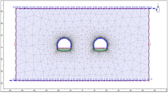
Figure 22.
FEM of tunnel ovalization for the C3 excavation and support system.
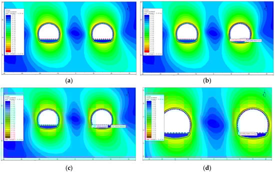
Figure 23.
C3 section. (a) Total displacement; (b) Axial force; (c) Bending moment; (d) Shear force.
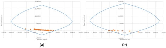
Figure 24.
C3 section under earthquake loading. (a) Lining; (b) Slab.
As seen in Table 12 and Table 13, the analysis of the inverted arch excavation and support systems suggested that the C3 rock class of the Erkenek Tunnel at K76 + 950 had sufficient capacity to satisfy the shear strength requirements.
Table 12.
Analysis of the lining and slab for the C3 section under earthquake loading.
Table 13.
Base shear force check of the C3 inner lining structure under seismic support conditions.
The ovalization behavior of the C2 tunnel section at K76 + 200, modeled using the FEM, is illustrated in Figure 25, and the corresponding analysis results are presented in Figure 26 and Figure 27.
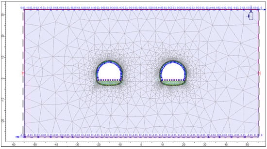
Figure 25.
FEM of tunnel ovalization for the C2 excavation and support system.
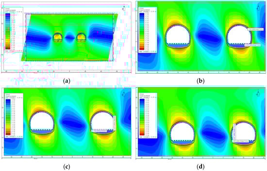
Figure 26.
C2 section. (a) Total displacement; (b) Axial force; (c) Bending moment; (d) Shear force.
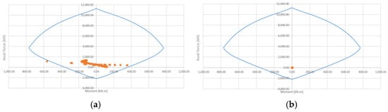
Figure 27.
C2 section under earthquake loading. (a) Lining; (b) Slab.
Table 14 and Table 15 demonstrate that the C2 rock class at K76 + 200 of the Erkenek Tunnel possesses sufficient capacity to satisfy the shear strength requirements. The ovalization of the C2 tunnel section at K76 + 200 was also investigated for the invert. Its ovalization model by FEM is given in Figure 28, and the analysis results are given in Figure 29 and Figure 30.
Table 14.
Analysis of the lining and slab for the C2 section under earthquake loading.
Table 15.
Base shear force check of the C2 inner lining structure under seismic support conditions.
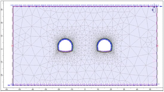
Figure 28.
FEM of tunnel ovalization for the C2 excavation and support system (with invert).
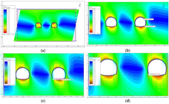
Figure 29.
C2 section (with invert). (a) Total displacement; (b) Axial force; (c) Bending moment; (d) Shear force.
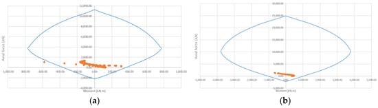
Figure 30.
C2 section (with invert) under earthquake loading. (a) Lining; (b) Slab.
The results given in Table 16 recommend that the C2 section (with invert) could safely fulfill the shear strength requirements. Finally, the ovalization model of the B3 tunnel section (with invert) at K77 + 200 by FEM is shown in Figure 31, and the corresponding diagrams are given in Figure 32 and Figure 33.
Table 16.
Analysis of the lining and slab for the C2 section (with invert) under earthquake loading.
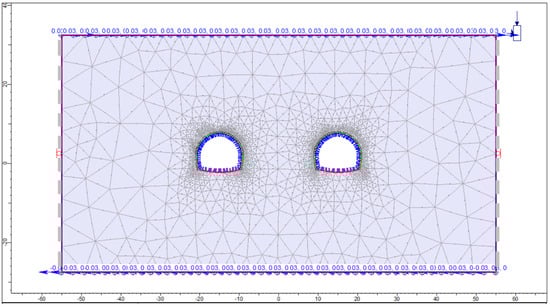
Figure 31.
FEM of tunnel ovalization for the B3 excavation and support system (with invert).
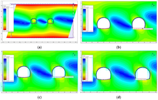
Figure 32.
B3 section (with invert). (a) Total displacement; (b) Axial force; (c) Bending moment; (d) Shear force.
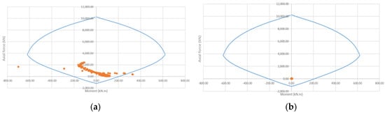
Figure 33.
B3 section (with invert) under earthquake loading. (a) Lining; (b) Slab.
The results in Table 17 suggest that the B3 tunnel section (with invert) could safely serve under shear forces.
Table 17.
Analysis of the lining and slab for the B3 section (with invert) under earthquake loading.
In conclusion, the numerical results of tunnel ovalization—including bending moments, shear forces, and deformed shapes at critical cross-sections—corroborate the post-earthquake field observations, particularly the observed crack patterns (location and direction).
8. Recommendations for the Secondary (Final) Tunnel Lining
The summary of the proposed final lining for the Erkenek Tunnel is given in Table 18. As shown, reinforcement of the final lining with steel bars and fibers is recommended. The inclusion of these reinforcements will enhance the tensile strength and toughness of the tunnel lining concrete throughout all regions. Moreover, this reinforcement will increase the energy absorption capacity of the final lining concrete and inhibit the propagation of micro-cracks.
Table 18.
Recommendations for the secondary (final) tunnel lining.
Steel bars to be used will comply with the EN 14889-1 standard. They will have a CE certificate for System 1 (for structural use). The minimum dosage criteria specified in this certificate have to be met. The steel bars should have a slenderness ratio (L/D) greater than 65 and a nominal tensile fracture strength (Rm,nominal) of 2300 MPa. The utilization of glued hooked-end steel fibers is recommended to minimize the risk of fiber balling and to promote homogeneous mixing within the concrete. The performance of the steel fiber-reinforced concrete will be determined according to EN 14651, “Test method for metallic fibered concrete—Measuring the flexural tensile strength (limit of proportionality (LOP), residual)”. In these tests, a mean residual flexural strength of fR,3m= 6.4 MPa will be targeted. In addition to this reinforcement, it is recommended to use a steel wire mesh at a rate of 35 kg/m3 (5D 65/60 BG) for the NATM C3-C2 with invert and B3-B2 classes of the tunnel.
9. Conclusions
Two huge Kahramanmaras earthquakes on 6 February 2023 and a series of aftershocks hit Turkey, Syria, and the surrounding region. Thousands of buildings collapsed, and critical transportation infrastructure in the earthquake-affected region suffered from heavy damage. The Erkenek Tunnel was one of the extensively damaged highway tunnels and the destructive earthquakes severely ruptured and collapsed its reinforced concrete lining at some sections. This study addressed the assessment and redesign of the tunnel’s internal lining structures, focusing on the most critical sections at K76 + 950, K76 + 200, and K77 + 200. For static conditions, the proposed strength and deformation parameters were used. For seismic conditions, the DD-2 earthquake ground motion level—with a 10% probability of exceedance in 50 years (return period of 475 years) as specified in the Turkish Earthquake Code—was considered. This approach is also expected to satisfy controlled damage requirements under the DD-1 earthquake ground motion level (2% probability of exceedance in 50 years, return period of 2475 years), ensuring life safety while limiting repairable damage.
Back-analysis conducted in this study revealed that the primary tunnel support system is operating under significant stress even under static loads, particularly at critical tunnel sections, performing near its limit. Observed displacements in severely damaged inner lining sections indicate that failures may have occurred in the primary support system due to the seismic forces. As a result, the primary support system in its current state does not substantially contribute to the overall stability of the tunnel lining. Strengthening the hinged steel elements embedded within the steel mesh-reinforced shotcrete was regarded impractical due to structural complexity and the critical locations of the damaged tunnel segments. Therefore, the newly designed inner lining is intended to act as the final support system along the entire tunnel length.
Based on the findings of this study, the following conclusions can be drawn;
Removal of damaged sections:
- Internal lining structures will be dismantled at intervals not exceeding 12 m.
- During removal, the condition of each lining element (primary support system, steel sets, shotcrete with wire mesh) will be documented with photographs and recorded in reports.
- Displacement measurements will be conducted to monitor tunnel safety. Temporary support will be installed immediately in sections showing significant movement.
Temporary support system:
- Reinforced with 8 m long stainless IBO anchor bolts, with tensile tests performed to ensure sufficiency.
Repair and replacement:
- Damaged reinforced shotcrete and wire mesh will be renewed where necessary.
- Tunnel support will be upgraded using one size larger than the dimensions specified in the original design. Steel sets of size 120 will be installed in B1 and B2 support classes where none were previously used.
- After inspecting and, if necessary, replacing steel support elements and rock bolts, a primary support system of steel mesh (Q221 × 221) and shotcrete will be applied to level the surface up to the boundary of the inner lining concrete.
Construction sequence:
- The existing service road will be reopened to one-way traffic, with the opposite direction served by the single tunnel tube.
- Construction will proceed simultaneously at the entrance and exit of the tube.
- Damaged primary lining will be removed in 12 m segments while preserving existing inverts.
- Demolition will use pyrotechnic methods, with manual/mechanical removal for sections that cannot be dismantled otherwise.
- Primary lining in damaged sections will be reconstructed using reinforced concrete techniques.
- Voids between the ground and lining concrete will be grouted, followed by injection where required.
Soil and rock stabilization:
- Consolidation injection will be applied in zones with cracks or weak soil/rock to increase load-bearing capacity.
Dismantling details:
- Unreinforced concrete lining: 40 cm thickness; 9 mm diameter, 9 g cartridges; 60 cartridges per section at 40–70 cm intervals.
- Reinforced concrete lining: 65 cm thickness; same cartridge specification and spacing.
Final lining reinforcement:
- Reinforced with steel bars and fibers, supplemented by a steel wire mesh at 35 kg/m3 (5D 65/60 BG).
Monitoring and verification:
- All measurements will be verified on-site before construction.
- In situ conditions will be continuously monitored, any deviations from assumptions will be addressed immediately.
Funding
This research was funded by MALATYA TURGUT OZAL UNIVERSITY through project number “24G26”, “General Research Projects” code 44001, entitled “6 Şubat Kahramanmaraş Merkezli Depremlerin Karayolu Tünellerinde Oluşturduğu Sismik Deformasyonların İncelenmesi” (in Turkish) and “The APC was funded by the author”.
Institutional Review Board Statement
Not applicable.
Informed Consent Statement
Not applicable.
Data Availability Statement
The original contributions presented in this study are included in the article. Further inquiries can be directed to the corresponding author.
Conflicts of Interest
The author declares no conflicts of interest.
References
- Chang, Y.; Zhang, Y.; Zhang, H. Tectonic geomorphology of Türkiye and its insights into the neotectonic deformation of the Anatolian Plate. Earthq. Res. Adv. 2024, 4, 100267. [Google Scholar] [CrossRef]
- Şengör, A.M.C.; Özeren, M.S.; Keskin, M.; Sakınç, M.; Özbakır, A.D.; Kayan, İ. Eastern Turkish high plateau as a small Turkic-type orogen: Implications for post-collisional crust-forming processes in Turkic-type orogens. Earth Sci. Rev. 2008, 90, 1–48. [Google Scholar] [CrossRef]
- Britannica. Turkey, The Arabian Platform; Encyclopædia Britannica Inc.: Chicago, IL, USA, 2024; Available online: https://www.britannica.com/place/Turkey (accessed on 23 September 2024).
- Tanircan, G.; Eken, T.K. Preliminary Assessment Report of February 6, 2023, Mw7.7 Gaziantep, February 6, 2023, Mw7.6 Kahramanmaraş, and February 20, 2023, Mw6.4 Hatay Earthquakes; Bogazici University Kandilli Observatory and Earthquake Research Institute: Istanbul, Turkey, 2024. [Google Scholar]
- United States Geological Survey. File:M 7.8—Central Turkey.jpg. In Public Domain; Wikimedia Commons: San Francisco, CA, USA, 2025. Available online: https://commons.wikimedia.org/w/index.php?curid=128450427 (accessed on 5 April 2025).
- United States Geological Survey. File:M 7.5—4 km SSE of Ekinözü, Turkey.jpg. In Public Domain; Wikimedia Commons: San Francisco, CA, USA, 2025. Available online: https://commons.wikimedia.org/w/index.php?curid=128462280 (accessed on 5 April 2025).
- Presidency of Turkey, Presidency of Strategy and Budget. 2023 Kahramanmaras and Hatay Earthquakes Report. 2023. Available online: https://www.sbb.gov.tr/wp-content/uploads/2023/03/2023-Kahramanmaras-and-Hatay-Earthquakes-Report.pdf (accessed on 23 September 2024).
- Yao, C.; He, C.; Wang, T.; Chen, C.; Geng, P.; Dong, W.; Yuan, F.; Xu, G. Damages of highway tunnels during 2022 Luding earthquake (Mw= 6.6). Soil Dyn. Earthq. Eng. 2024, 177, 108357. [Google Scholar] [CrossRef]
- Zhang, X.; Jiang, Y.; Maegawa, K. Mountain tunnel under earthquake force: A review of possible causes of damages and restoration methods. J. Rock Mech. Geotech. Eng. 2020, 12, 414–426. [Google Scholar] [CrossRef]
- Ansari, A.; Rao, K.S.; Jain, A.K.; Ansari, A. Deep learning model for predicting tunnel damages and track serviceability under seismic environment. Model. Earth Syst. Environ. 2023, 9, 1349–1368. [Google Scholar] [CrossRef] [PubMed]
- Callisto, L.; Ricci, C. Interpretation and back-analysis of the damage observed in a deep tunnel after the 2016 Norcia earthquake in Italy. Tunn. Undergr. Space Technol. 2019, 89, 238–248. [Google Scholar] [CrossRef]
- Jain, H.; Kumar, J. Displacements and stresses around a circular tunnel in an elastic medium with pseudo-static horizontal earthquake body forces. Comput. Geotech. 2023, 162, 105663. [Google Scholar] [CrossRef]
- Xin, C.; Feng, W.; Song, D.; Huang, S.; Liu, X. Seismic damage to non-fault-crossing and fault-crossing tunnels: Comparative study of the 2008 Wenchuan earthquake (Mw 7.9) and the 2022 Menyuan earthquake (Mw 6.7). Eng. Fail. Anal. 2024, 166, 108843. [Google Scholar] [CrossRef]
- Zhang, Z.; Chen, F.; Li, N.; Swoboda, G.; Liu, N. Influence of fault on the surrounding rock stability of a tunnel: Location and thickness. Tunn. Undergr. Space Technol. 2017, 61, 1–11. [Google Scholar] [CrossRef]
- Zhao, H.; Wu, Q.; Zeng, Y.; Zhou, L.; Wen, Y. Analytical solution for longitudinal response of tunnel structures under strike-slip fault dislocation considering tangential soil–tunnel contact effect and fault width. Buildings 2025, 15, 2748. [Google Scholar] [CrossRef]
- Chen, P.; Geng, P.; He, D.; Chen, J.; Xiang, C.; He, C. Evaluation model of circular tunnel lining subjected to dislocation earthquake point source in semi-infinite media. Tunn. Undergr. Space Technol. 2024, 146, 105635. [Google Scholar] [CrossRef]
- Chen, P.; Geng, P.; He, D.; Wang, T.; He, C. A novel tool for seismic response analysis of tunnel in multilayered media based on kinematic earthquake source. Eng. Geol. 2024, 340, 107675. [Google Scholar] [CrossRef]
- Chen, P.; Geng, P.; Chen, J.; Gu, W. The seismic damage mechanism of Daliang tunnel by fault dislocation during the 2022 Menyuan Ms6.9 earthquake based on unidirectional velocity pulse input. Eng. Fail. Anal. 2023, 145, 107047. [Google Scholar] [CrossRef]
- Du, J.; Yan, S.; Sun, W.; Li, Y.; Cao, M. Analysis of Tunnel Lining Damage Characteristics Under the Combined Actions of Fault Dislocation and Seismic Action. Appl. Sci. 2025, 15, 1150. [Google Scholar] [CrossRef]
- Xia, C.; Sun, F.; Zhou, Z.; Liu, T.; Qi, C. Quantitative design method for anti-dislocation joints for tunnels passing through active faults. Tunn. Undergr. Space Technol. 2022, 124, 104489. [Google Scholar] [CrossRef]
- Sun, R.; Xu, H.; Yan, Q.; Yang, K.; Zhang, C. Effects of seismic buffer thickness on a circular rock tunnel considering seismic damage form and failure state. Int. J. Rock Mech. Min. Sci. 2024, 183, 105892. [Google Scholar] [CrossRef]
- Wang, L.; Cui, G.; Zhang, C.; Zhao, Y.; Ma, J.; Min, B. Failure characteristics and seismic behavior of steel basalt hybrid fiber reinforced concrete lining for the tunnel in strong earthquake areas. Eng. Fail. Anal. 2024, 162, 108357. [Google Scholar] [CrossRef]
- Kijewski-Correa, T.; Roueche, D.B.; Mosalam, K.M.; Prevatt, D.O.; Robertson, I. StEER: A community-centered approach to assessing the performance of the built environment after natural hazard events. Front. Built Environ. 2021, 7, 636197. [Google Scholar] [CrossRef]
- Wang, T.T. Characterizing crack patterns on tunnel linings associated with shear deformation induced by instability of neighboring slopes. Eng. Geol. 2010, 115, 80–95. [Google Scholar] [CrossRef]
- Chen, Z.; Shi, C.; Li, T.; Yuan, Y. Damage characteristics and influence factors of mountain tunnels under strong earthquakes. Nat. Hazards 2012, 61, 387–401. [Google Scholar] [CrossRef]
- Srivastav, A.; Yadav, V.; Kainthola, A.; Pandey, V.H.; Dangwal, V.; Singh, T.N. Boundary element coupled structural analysis of Lesser Himalayan railway tunnels: A case study of the Shivpuri–Byasi section, Rishikesh–Karnaprayag BG rail link, Uttarakhand, India. J. Earth Syst. Sci. 2024, 133, 244. [Google Scholar] [CrossRef]
- Sheorey, P.R.; Mohan, G.M.; Sinha, A. Influence of elastic constants on the horizontal in situ stress. Int. J. Rock Mech. Min. Sci. 2001, 38, 1211–1216. [Google Scholar] [CrossRef]
- Brown, E.T.; Hoek, E. Trends in relationships between measured in-situ stresses and depth. Int. J. Rock Mech. Min. Sci. Geomech. Abstr. 1978, 15, 211–215. [Google Scholar] [CrossRef]
Disclaimer/Publisher’s Note: The statements, opinions and data contained in all publications are solely those of the individual author(s) and contributor(s) and not of MDPI and/or the editor(s). MDPI and/or the editor(s) disclaim responsibility for any injury to people or property resulting from any ideas, methods, instructions or products referred to in the content. |
© 2025 by the author. Licensee MDPI, Basel, Switzerland. This article is an open access article distributed under the terms and conditions of the Creative Commons Attribution (CC BY) license (https://creativecommons.org/licenses/by/4.0/).