Abstract
Recycling plastic waste (RPW) benefits the ecological footprint. Therefore, the authors test its mixing by magnetic hydrodynamic MHD nanofluid materials such as alumina in two sizes () prepared into a new device called the incubator installed in the desktop injection machine to enhance its solubility by taking advantage of the mixture’s heat via defining the oblique stagnation-point slip flow (OSPSF) of a nanofluid in two dimensions. The paper has been innovative in mathematically identifying the operating parameters’ values for the injection flow mechanism (IFM) via controlling in Riga magnetic field and piston orifice pressure using a meta-heuristic algorithm called WSA. The proposed (IFM) is used to experimentally enhance the mixture properties via parameters’ control to meet the output quality and predict the control equation for the Riga plate. IFM controls the amount of pushed nanoparticles in the mixture with a ratio of plastic to aluminum approximate by 96.1%: 3.9%. The defects were reduced by approximately 23.21%, with an increasing system performance of 70.98%.
1. Introduction
Plastic has been produced quicker than any other material since the 1970s. Global primary plastic output is anticipated to reach 1100 million tonnes by 2050. In addition, fossil fuels or “virgin” feedstock make up around 98% of single-use plastic items. By 2040, it is anticipated that the proportion of greenhouse gas emissions related to the manufacture, consumption, and disposal of conventional plastics derived from fossil fuels will increase to 19% of the global carbon budget. Systemic reform is required to limit plastic garbage flow into the environment. Less than 10% of the [1] tons of plastic trash produced worldwide has been recycled. Millions of tons of plastic garbage are either lost to the environment or transported, often over great distances, to places where it is burnt chiefly or deposited. The value of waste plastic packaging is reportedly lost annually to sorting and processing alone to US$ 80–120 billion [1]. Despite current efforts, it is predicted that 75 to 199 million tonnes of plastic are still present in our seas today and are expected to increase by almost three times in 2040 if we don’t change how we manufacture, consume, and discard plastic will face catastrophe [1]. High quality is a crucial issue requirement, whether in production or in services, achieved by smooth business progress, which brings customer loyalty and increasing demands [2,3]. This paper proposes a modification of the desktop injection machine to enhance the melting of plastic waste by mixing it with nanofluid materials, enabling the mixture to produce high-quality products and be remanufactured. There are several methods for manufacturing nanoparticles, including friction and pyrolysis. The new incubator combines the two methods to collect agglomerates at a depth of the mixture and to leave the solo particles at the surface layers to be easy to form. In the process of friction, large and fine particles are rubbed in a planetary ball mill to reduce their size. The resulting particles are classified as aerobic to recover the nanoparticles. While during pyrolysis, liquids and gases are forced to pass through an orifice under high-pressure conditions to make clumps rather than single elementary particles like particles absorbed by the Riga plate [4]. A viscous fluid’s free convective and mass transfer flow through a porous media has been investigated by several researchers. While the porosity of the medium may not always be constant, the permeability of the porous medium is considered to remain constant in this study. Kim [2] observed the changing suction through the vertical porous moving mold and unstable convective heat. K.D. Singh and Sharma [3] have studied the issue of three-dimensional free convective flow and heat transfer via a porous media with periodic permeability. The heat and mass transfer in the MHD flow of a viscous fluid via a vertical tube under oscillatory suction velocity has been examined by S.S. Das et al. [5]. While S.K. Khan et al. [6] studied the heat transmission across a porous material moving with harmonic disturbance in a three-dimensional viscous flow. Postelnicu [7] investigated the impact of an MHD on the free convection of heat and mass from vertical surfaces in porous media statistically while taking Soret and Dufour effects into account as analysis of Y.J. Kim [8]. All these studies motivate us to try to mix the MHD with RPW material through the injection process to enhance the efficiency of the mixture. The better-quality product increases the manufacturer’s competency in the market and enhances customer demand to make human lives more comfortable. The working parameters are most significant in producing good quality products in an injection molding process and rely on material characteristics [9]. The working parameters such as injection pressure, the up melt temperature contributes, viscous fluid’s free convective, and mass transfer flow rate need to be optimized to produce good quality homogenous metal-plastic mixture (HMP) parts via characteristics tackling by classifying the products and their utilize (RSM), which is supported by the metaheuristic technique. It delivers a well-organized procedure for parametric optimization to help the process adaption according to tolerance deviation during working rapidly [10,11,12]. The authors rely on the Cause and effect diagram to explain most working parameters to study their impact when using the Design of Experiment tool (DOE) and elect some of them according to visual (ANOVA) recommendations, which are constructed to determine which working parameters are most critical and substantial. The convenient injection molding process set-up depends upon the trial and error method or technician or operator’s experience [13,14], but this negates the autonomy of the process and is based on the trial-and-error method, which is considered a time-consuming and non-cost-effective technique, which is not acceptable in the plastics manufacturing industry. Therefore, the authors used a metaheuristic method that rapidly sets the operating parameters’ values according to molten material properties changes due to the environment, material, and injection method effect. The problems and defects related to the quality of plastic products encountered in injection molding operations include air bubbles, flow marks, flashes, short pieces, burns, and other surface marks [15,16,17,18]. The novelty of the present study is to improve the melting of recycled plastic waste (RPW), the research describes a new modification to the injection machine method that enables the mixing of magnetic hydrodynamic MHD materials like β(core) and β(skin). Consequently, the authors use an over Riga surface formed of magnets and electrodes inserted in tubes of molten RPW when the Lorentz force decreases exponentially. The authors suggest using an auxiliary device attached to the injection machine to prepare the molten material for force toward the preform die and examine the effect of constant medium permeability with time-dependent variable suction on a viscoelastic fluid flow [18]. Finally, a perturbation similarity strategy is used to solve the set of ordinary differential equations that represent part of injection mechanism to address the insufficiency of the boundary condition. The Lorentz force and the fluid’s elasticity both lower the velocity, and this effect is more noticeable for heavier species [19,20]. The most intriguing finding is the velocity fluctuation that can be seen close to the mold surface as a result of elastic components, a sink, and a heat source that reduces friction in the higher layer [21,22]. It is demonstrated that for scenarios of aiding and opposing flows, the slip parameter changes, and without the slip parameter , for more significant impacts of nanoparticle volume fractions, the standard and tangential velocity profiles lower. In some case studies, the parameters under control are confined to being integers and behaves as a multi-constraint/parameter problem; therefore, researchers resorted to considering the problem as an integer programming uses the mathematical optimization or feasibility program in which some or all of the variables are restricted to be integers [23,24,25]. The RPW is dried for 2 to 3 h before beginning the mixing operation and then passes through different temperature barrels, which up melt the material and inject it into the incubator cavity at a specific injection pressure. Air bubbles or sink marks appear on the surface of moulded parts due to low material flow rate and injection pressure [26,27], and authors observe the bad effect of residual stresses that must be released because they lead to deformities created during shrinkage. The mold temperature is the primary cause of flow marks and flashes on the surface of the molded part. While the shock absorption weakness or color lines appear when improper cleaning of the process, lubrication leakage, burned material in the barrel, melting temperature, and mixing of dust particles or other materials mix with the RPW [28]. The working parameters can be optimized to improve the quality of the molded part through the proposed IFM system. The proposed IFM aims at manufacturing through two phases; the first interested in preparing the RPW mixture and fed by nanoparticles through two paths (piston orifice pressure aisles and push toward Riga magnetic field) where the β(core) pushes into the core while β(skin) is still in the surface layer, and the second in parallel controlling the Riga surface magnetic fields and the pressure using the WSA algorithm when pushing nanoparticles into melted RPW. The injection molding process has mainly three stages: mold filling stage, cooling stage, and ejection stage. The cooling stage has a significant influence on the quality of the product and the productivity of the process [29,30]. During the manufacturing of plastics parts, the quality focuses on checking each part is free of the following defects such as hard fitting, flow marks, flashes, sink marks, shrinkage, high air bubbles, mold lines, and other surface marks depending upon thirteen working parameters for injection machine such as melting temperature, injection pressure, die temperature along with flow rate, viscosity, screw speed, packing pressure, holding pressure, packing duration, filling time, injection time, cycle time, and injection speed. At the same time, incubators have five controlled parameters: magnetic field strength, number of electrodes, contact angle, dimensionless drag force, and non-dimensional shear stress of flow inside. Poor quality products have an impact on cost and lead times in addition to the client relationship. In this work, the frame of a window sector is taken as a case study that encounters many quality defects recorded by imaging and fed to the system to count the like shrinkage or hard fitting, air bubbles or voids, flow marks, flashes, short piece, black dots, shock absorption, burns marks, weld lines, warpage, die lines, sink marks, and surface quality. This molded part has many complaints and poor feedback from customers that disturb the customer relationship with the company [31]. The weighted superposition attraction (WSA) method and the linear decreasing particle swarm optimization algorithm were utilized for working parameter selection in the multi-objective optimization model and outperformed the native PSO [32,33]. This paper focuses on predicting the optimum working parameters during mixing to separate the MHD components (e.g., molten β(core) and β(skin)) used to mix with recycling plastic waste, to enhance the machining process through tracking the contact angle, the dimensionless drag force or non-dimensional shear stress on the facing surface, and heat transmission of the mixture because are the industrial technical parameters of interest or gradients in this field [34]. The paper also discusses the quality of classification and separation of the molten β(core) and β(skin) and the quality of the mixture using RSM [35] to check the results accurately. The Problem description is discussed in Section 2. The proposed IFM mechanism is discussed in Section 3, while explaining the incubator design and its mechanism in Section 4. The RPW preparation physically and injection machine modification mechanism are discussed by implementing IFM experimentally to adjust significant parameters using a mat-heuristic algorithm named WSA in Section 5. The election of significant working parameters to build the suitable control equation discuss in Section 6. The authors check for IFM validation by testing the products formed by the new mixture in Section 7 by analyzing the testing results (before and after) and comparing the effectiveness of WSA by thirteen different algorithms. Finally, discuss these results in the conclusion Section 8. The goal here should be to produce a specific product with the lowest possible cost, defect, and production time.
2. The Problem Description and Motivation
The primary purpose of this work is to test the efficiency of enhancing the RPW forming in molding by mixing it with MHD fluid containing nano particles of β(core) and β(skin) into a nanoliquid solution to enhance the viscosity and reducing the empty particles. The parts are segregated based on different defects shown in Table 1 for other injection molding processes to stand over the cause of the defect, as illustrated in Figure 1. The Fishbone diagram for a product that represents the highest number of total defects as discussed in the Pareto chart and illustrated in Figure 2. The air bubbles caused due to failure in setting injection time, suction process, lack of parameters setting, and other significant factors such as tackling methodology and tracking the oblique Stagnation-Point Flow [34,35,36,37]. The authors investigated the convective flow caused by hybrid MHD flow along the slip effect by considering the over-Riga die surface. Some researchers examined the combined convective flow near an SP and offered double solutions in the presence of liquid solution-based binary hybrid nanoparticles via an over-vertical Riga die surface [38]. The dynamics of mass and energy transfer in a micro rotational flow with mixed convection and suction/injection across an over-Riga die surface were recently examined by Rafique et al. [39]. They demonstrated that the modified Hartmann parameter causes the fluid’s velocity to develop. To deal with the RPW in production, its properties must be improved by mixing it with nanomaterials via nanofluid. The mixture is pressured in an incubator device that is fixed to the desktop injection machine. The incubator consists of three pistons and a Riga plate installed inside the incubator to absorb the nanomaterials, push it into the molten plastic, and then pump the mixture with the third piston towards the die. It is suggested to use a WSA to adjust the operating parameters to ensure a good blend. The WSA hybridizes with RSM to elect the significant working parameters and set their values, which are checked by DOE mathematically. The two main successive phases are manipulated through IFM methodology to understand the relationship between material properties and working parameters.

Table 1.
Rejection according to poor mixture and parameters control for four products.
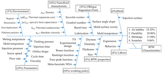
Figure 1.
Fishbone diagram to identify the root cause of recycling process.
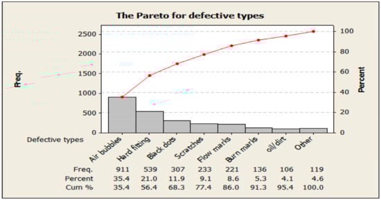
Figure 2.
The famous types of defective while injecting the RPW.
Table 1 records the major defects before implementing IFM methodology for injecting four different products (Mineral water bottles, Window frames, Helmet, and Houseware), which revealed that common defect types such as air bubbles (e.g., cavity) contribute 35.42% of total defects, hard fitting (e.g., twist or wrong size) contributed 21%, flow marks contributed 8.6%, and shock absorption (Sab) 11% of total defects led to rejection. The comparison among process-defected data shows that hard fitting, air bubbles, flow marks, and shock absorption (Sab) still contribute to the highest rejection rate. So, this study focuses on improving the quality by optimizing responsible working parameters such as injection pressure, viscosity, up-melt temperature, and flow rate. Flow marks and air bubbles on the die part surface reduce the quality of the part and lead to rejection from the side customer. Many complaints were received from customers due appearance of air bubbles and flow marks on the surface of molded parts. The weight of each is the current point of an agent (i) for each parameter (j) at each iteration according to their impacted rank extracted from the DOE.
3. The Mechanism of the IFM Network Methodology
The optimization approaches are divided solution techniques into four categories: heuristics, mathematical programming, meta-heuristics, and hybrid mathematical processes by heuristics procedures, known as the mat-heuristic approach. The purpose of the intervention of the mathematical optimization techniques is to define the problem at hand explicitly. As a result, mathematical programming techniques frequently don’t work as well as they could. Heuristic methods can provide flawless or almost flawless solutions to a problem in less time. However, because they were frequently created in response to particular issues, it is difficult for them to be broadly employed, reducing their effectiveness. In contrast, it would not be wrong to claim that meta-heuristic algorithms are often more effective than mathematical programming and heuristic techniques in many complex issue settings. Improving RPW properties by mixing it with an MHD containing two sizes of nanomaterials of β(core) and β(skin), sucking the metal from the MHD to feed the RPW through the Riga plate to improve injection processes for plastic products with high quality. Therefore, the work-study checks the mixture validation in two domains, in the injection pistons cylinders to generate β(core) and also in the incubator through Riga to pick β(skin), taking into account an accessible stagnating point or line simultaneously. The newly created Weighted Superposition Attraction (WSA) swarm-based optimization method controls of significant working parameters to control on the amount of β(core) in the mixture core and β(skin) in the skin surface of the mixture. The Pseudocode nomenclatures of the IFM network variables are shown in Table 2. While the correlations of these mathematical notations are written in Table 3 to determine the stagnation point precisely. The working code of search, all directions for predicting the near-optimal value for significant parameters, consists of 11 Paces pseudocode as shown in Table 4 to build the relationship among the parameters and its defect causes’ opportunities to qualify the process to adapt autonomously as the main objective of this study discussed in the experimental Section 5. The Minitab (16) is used to extract the basic optimal parameters by building a hidden optimization network that gathers the different parameters and the consequential outputs’ defects. Tests are conducted with those parameters while maintaining the required levels of quality. A typical search algorithm, like mathematical WSA, finds the search space of an optimization problem using a few methods that allow the algorithm to visit and assess various places of the search space, such as RSM and the DOE. The main phases of the suggested IFM system are shown in Figure 3. The IFM Network consists of thirteen parameters that elect the Melting temperature, injection pressure, flow rate, and viscosity as a shared significant parameter that joins the second layer that consists of five expected incubator parameters opportunities and tackling as illustrated in Figure 3.
Table 2.
The IFM methodology Network variables and parameters.
Table 3.
The thermo-physical idioms of nanofluid mix properties relationships in incubator.
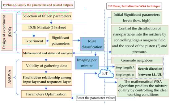
Figure 3.
IFM Network framework.
The IFM technique uses the mathematical WSA algorithm, which depends on RSM to categorize and determine the search orientation of the agents (i.e., significant parameter) of a swarm (i.e., whole parameters that have a range of values, low and high), by implementing the superposition principle in combination with the attracted movement of agents through a neighbor generation mechanism.
RSM may be used to remove obstacles between the bi-logical learning system and traditional artificial learning techniques and discovers six significant working parameters for the machine and five for the incubator, which have two empirical tie parameters, which are (Temperature and Viscosity). The core tenet of RSM is that recurrent tuning is unnecessary for the hidden neurons in a feedforward IFM network with a single hidden layer [40]. According to Tolouei-Rad, which is the origin of the mathematical WSA as shown in Table 4, which declares the IFM Pseudocode that discusses the WSA a unique member of the swarm intelligence-based methodologies that aim to characterize and duplicate the continually changing superposition because of the dynamic nature of the system and the attractive movement of agents. The mathematical WSA idea is set in motion by the configuration of algorithm parameters. WSA uses fitness values to determine the order of the solutions. By choosing a target place, the solutions are relocated there. The search direction for each solution is then decided per the target point, and its fitness value after the fitness values of the target point has been assessed. Each answer is then shifted in the chosen direction. Finally, each solution’s fitness value is assessed. Until a termination requirement is met, this process is continuous. The authors noticed that there is an inner source of heat caused by the electrodes installed in the Riga plate, which also affects the magnetic field strength, which must be controlled to prevent the shock absorption weakness caused by burning the nanoparticles over the upper mixture skin. Therefore, the authors resorted to tracking via imaging the nanoparticles and their quantity per minute by predicting it through a meta-heuristic WSA algorithm. The prediction reflects the temperature of the electrodes permeated with the mixture and can be controlled.
Table 4.
Pseudocode of IFM mechanism to control the distribution of nanoparticles into the mixture.
Table 4.
Pseudocode of IFM mechanism to control the distribution of nanoparticles into the mixture.
| Step | Action Identification |
|---|---|
| Pace (1): | Initialize the picking parameters from the cause and effect diagram for a specific defect opportunity that has a maximum frequency as discussed in the Pareto chart for the whole defect opportunities. |
| Pace (1.1): | with n limits for all candidate parameters of the injection machine. |
| Pace (1.2): | with m limits for all candidate parameters of the incubator device. |
| Pace (1.3): | . |
| Pace (2): | Prepare a parameter range, estimate the constraint, and then generate the pre-defined number of initial solutions i.e., Cast product quality (Shock-absorbing, dimensional, air bubble-free). |
| Pace (3): | Analyse individuals’ degree of fitness. |
| Pace (3.1): | Evaluate fitness values of the initially picked solutions to modify significant variables and their related fitness |
| Pace (4): | Move to pace (11) if the wanted objective is met; otherwise, jump to Pace (5). |
| Pace (5): | }. |
| Pace (5.1): | While Iteration < Max_iter |
| Pace (5.1.1): | Rank solutions according to their fitness values |
| Pace (5.1.2): | Assign a weight to each solution by considering their ranks |
| Pace (5.1.3): | Determine a target point (superposition) to move the solution toward it |
| Pace (5.1.4): | Evaluate the fitness value of the target point |
| Pace (5.1.5): | Determine the search direction for each solution by considering the target point (superposition) and its fitness value. |
Pace (5.1.6): Move each solution toward each determining direction
Pace (5.2): Picking a random solution and fed the DOE experiment.
Iteration = Iteration +1
End while;
Pace (6): Cross the main mesh’s cusp and check IFM Network list on the cloud.
Pace (7): Create the main (RSM) for the based on Equation (1)
Hint: does a least square method LSM calculate coefficients.
Pace (8): Training IFM Network by to create the conditional constraints approximately.
Pace (9): Find the reaction surface’s ideal design by the WSA and create first acceptable solution
Pace (10): Alter and go back to Pace (3).
Pace (11): Continuous Searching for the optimum solutions locally focused search for the best candidate.
where the and signify the components of solid displacement and velocity in the directions of and , respectively. Additional mathematical notations or symbols are demarcated as the pressure of the nanofluid, the applied current density in the electrodes, the temperature of the nanofluid, the magnetization of the permanent magnets and the respective width of the electrodes and magnets.
//injection phases using three pistons:
for (i =1:AA)
for (j = 1:D)
end
for (d = 1:D)
end
//negative injection or suction for piston 2:
for (j=1:D)
end
for (d = 1:D)
end
else
//the boundary conditions according to OSPF:
The step length of moving over the solutions mesh set by 0.0034, is 0.0015:0.1, while the λ is set between [−0.75:0.95] for this example of molded process as illustrates in Figure 4 [40].
end
end
end
end
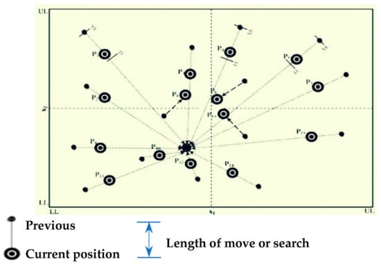
Figure 4.
Positioning updating mechanism for whole working parameters.
The contact angle, the dimensionless drag force or non-dimensional shear stress on the facing surface, and heat transmission are the technical and industrial parameters of interest or gradients, and they are defined mathematically as:
3.1. The Incubator Device Mechanism (RPW Preparation)
When fluid from any source contacts a solid obstacle obliquely at any angle of incidence, oblique stagnation point flow (OSPF) emerges [41]. It is important to note that all electrodes are made of carbon in an industrial electrolytic cell used to extract aluminum. The authors created and built a specific prototype test injection machine using a fluid mechanics laboratory with a consultant U.S.C.C house in the 10th of Ramadan City to examine the impact of the critical parameters illustrated in Figure 1 (Egypt).
The prototype of modified device in the desktop injection machine consists is to install an incubation device to the injection machine divided into two sections. The first section receives the nanofluid materials (β(skin) and β(core)) pushed by the first and third pistons to meet with the molten plastic waste through the porous surface of Riga. The mixture must be rotated continuously to prepare it to be pushed by the middle second piston towards the die as illustrated in Figure 5.
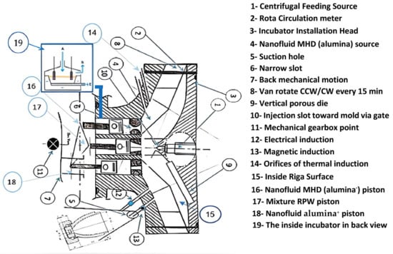
Figure 5.
The prototype of the incubator’s liquid sector layout using over Riga surface.
The authors study the physical properties of the mixture and adjust the operating parameters that qualify it to provide good plastic products. The mechanism is done over three steps as shown in Figure 6, which depicts a schematic prototype injection machine diagram (front view). The mechanism of the flow is illustrated in Figure 6 (i.e., mix MHD and RPW) and Figure 7 (i.e., mixture pushing in the cylinder toward die). The Riga plate adheres to two coaxial triangular pieces to combat the air bubbles’ path. The external incubator has a jacket-like design and is triangular in shape, measuring 23 × 23 × 23 cm. It is made of a translucent stainless sheet that is 0.15 cm thick. Using translucent 18 × 18 cm stainless, a section of the base was created to make it simpler to observe the vane-setting angle. The inner cistern is a 12 cm by 12 cm by 23 cm stainless sheet connected coaxially with the inner cistern’s diameter. According to our assurances, the new research is novel, will significantly influence the fields of mathematics and engineering, and will be interesting to other researchers. Therefore, the authors concentrate on capturing and controlling the passage of air bubbles by first detecting their path and stagnation point when mixing using the aided device illustrated in Figure 4. As a result, the researcher is interested in categorizing and determining its pushing impact on air in the center chamber in a steady-state condition [42,43,44]. In order to improve the robustness of air bubbles detection in injection machine processes, it recommended (detecting air bubbles paths).
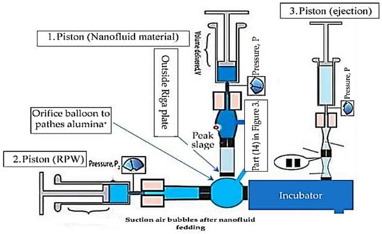
Figure 6.
The distribution of incubator three pistons.
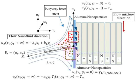
Figure 7.
Physical mixture injection distribution between pistons (1), (3) under Lorentz force.
This work demonstrates the capability to implement IFM thinking in unseen layers of processes’ mechanisms with imaging techniques to increase its reliability by controlling it through IoT to create central control.
3.2. The Physical Mixture Characteristics
The study focuses on injected material flow characteristics, whether nanofluids or RPW in the piston cylinder or into the incubator, and defines the impact of working parameters values suit forming mechanism. The main defect caused is bubbles, which are considered high-risk situations when all bubbles enter the alveolar orifice balloon illustrated in Figure 3 part (14). Regularly cause tides in the pleural space and enhances the effect of artificially reduced pressure, which quickens the suction process for pumping the nanofluid to minimize the air bubbles transfer to the RPW as discussed in the next Figure 5, Figure 6, Figure 7 and Figure 8. To reach the low-severity threshold when bubbles go far away from pleural space orifice and reduce the synthetic negative pressure. To manage the formation and routes of air bubbles, this research emphasizes the use of flow rate monitoring that maintains precise and steady output value [44].
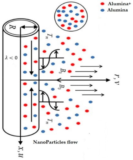
Figure 8.
Microscopic view of hybrid nanofluid sizes at the nozzle of pistons (2).
The considerable stream rate turns out to be caused by rotor-stator contact in the incubator appearing in parts (2, 8) in Figure 3 based on two-code pumps. To regulate the variations, the research recommends creating inventive injection machines and modifying several key variables. This flow type is analyzed mathematically by multiplying the orthogonal stagnation-point flow by the shear factor of the flow against facing a surface [43,44,45] as several engineers and academics have researched the 2D constant flow of a Newtonian liquid near an OSPF. Lok et al. [46] observed the constant viscous fluid flow through a stretchable sheet approaching a non-orthogonal stagnation point (NOSP). Therefore, the authors inserted part (14) in the piston path and noticed that tangential and Hiemenz components separate the stream function in mixture behavior in an incubator, as illustrated in Figure 7 for piston (1, 3) and Figure 8 for piston (2). Using a stretchy balloon, we studied how buoyancy force affected the NOSP flow in a micro-polar fluid. The effects of suction on an unsteady flow at an oblique stagnation point caused by MHD via a mimicking Nadeem et al. [47] similar mechanism over a sheet. Over a shrinkable/stretchable sheet, Li et al. [48] achieved twofold solutions of oblique stagnation-point flow in the presence of MHD subject to Cattaneo-Christov flux. is a Cartesian synchronizes or coordinates used to limit the model’s current flow configuration, where the upward and normal axes of the positive and are correspondingly extended along the plate surface. The flow is constrained to the planes and the axis synchronization is assumed to be transverse to the positive corresponding plane. According to theory, the slip velocity at Riga’s wall surface is expressed by . Moreover, the free stream or ambient field of inviscid fluid impinges obliquely on the Riga surface with a controlled velocity discussed in the second phase by , where while . It also, and express the constant wall surface and ambient temperature of the nanofluid, respectively. However, the contrary pattern will happen if the Riga surface is cooled (opposing flow) below the free-stream/far-field temperature . Then the second phase of IFM methodology interested in the control of nanoparticles amount fed to the RPW through control heat and cold case, respectively [49]. These expectations are the main motivation to enhance the RPW and make it easy to form with minimum defects and distribute the nanoparticles as illustrated in Figure 9, especially if following the Boussinesq approximation and deriving the steady of viscous equations to control OSPSF, which is considered one of the leading causes of defects discussed in Figure 1.
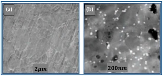
Figure 9.
Micrographic image SEM for (a) alumina(−) and (b) alumina(+) nanoparticles.
Recently observed the buoyant flow of a micro-polar MHD over a Riga sheet with a magnetic field toward an oblique stagnation point. They demonstrated that magnetic and micropolar factors increase MHD temperature. Therefore use the magnetic in heating control for the fluid [50]. The ISO 604 standard, developed by the International Standards Organization (ISO), specifies a method for determining the compressive properties of plastics under specified conditions and is compared to the international standard with ISO 10350-1 and ISO 10350-2 on fiber-reinforced composites with fiber lengths of 7.5 mm before curing. The plastic chips treated with nanoparticles are characterized by an increase in the density of nanoparticles, as illustrated in Figure 9 Micrographic image (SEM) with a grain scale of and .
4. The Experimental of IFM Network
The experiment begins by choosing the critical operational parameters, which were divided into categories by (RSM) demonstrated by (DOE) in front propagation and predicting the deviation in nanoparticle feeding brought on by a Lorentz effect, as discussed in Figure 6 above. A homogeneous transverse gravitational flux has highly conductive nanomaterials through a vertical porous die into a porous substance (i.e., part 9 in Figure 3) with time-dependent oscillatory permeability. Some of the mathematical equations feed a meta-heuristic technique called the weighted superposition attraction algorithm (WSA) in the backpropagation to reset the significant parameters to keep the product within standard specifications.
The experiment records eleven defect opportunities in the product during the machining process, as discussed in Table 1 above. The investigation identifies the root cause of process failure by failing to manage the oblique stagnation-point slip flow (OSPSF) of an MHD in two dimensions with buoyancy force over a vertical Riga surface (i.e., part 15 in Figure 3) as illustrated in Figure 10. Therefore, the authors’ check of injection flow parameters and heat transfer properties are also examined [51].
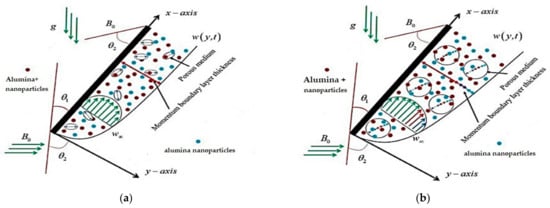
Figure 10.
The distribution of injection pressure for the three incubator pistons. (a) Piston (1, 3) nanofluid particles in cylinder piston; (b) Piston (2) nanofluid particles in above incubator section.
However, the experimental physical data of the based fluid and the β(core) or β(skin) nanomaterials are exhibited in Table 3, which the RSM classifies as struggling with the air bubbles and twist. The basic mechanical properties of the composite were analyzed, as shown in Table 5, such as hardness, fracture strength by the four-point bending method, and toughness which Single Edge-Precracked Beam analyzed with a depth 0.254 mm [52].
Table 5.
The physical data of the molten β(core) and β(skin) nanoparticles and the based liquid solution fluid.
5. The Election of Significant Working Parameters
According to the step length of movement between the lower and upper level [LL, UL], each parameter will generate neighbor sets, which consist in determining a search direction with a step length using a position updating mechanism, which is a crucial step in developing effective search algorithms. This mechanism is given by Equation (10), and artificial agent updates its position on dimension at iteration t as formalized by Equation (10).
where is the value of the position of artificial agent (parameter) on dimension (layer) at iteration , is the value of step length at iteration , is the search direction of artificial agent (toward lower value or toward upper value) on dimension j at iteration , and is the norm of the position vector of artificial agent on dimension at iteration , and , where −1 denotes the lower value LL, while +1 denotes the upper-value UL and 0 is the target value. The second term updates the position of an artificial agent via the second term [53,54]. Full factorial design technique is used to get the required experiments that are being performed through experiments that have been conducted 81 times. Replicates 1 suggests performing each experiment or test just once, considering three levels for each parameter, as shown in Table 6.
Table 6.
Process Parameters with molten material properties.
Figure 11 illustrates the effect of flow rate and viscosity and the effect of melting temperature and injection pressure, which must be controlled to resist the bubbles’ appears, while the injection speed causes the shock absorption-dot defects as illustrated in Figure 12 according to effect three significant parameters Flow-rate, Injection-speed, and temperature, which are related to screw speed, and injection pressure also an effect of melt-temperature have a direct impact on reducing the burning shock absorption-weakness defect.
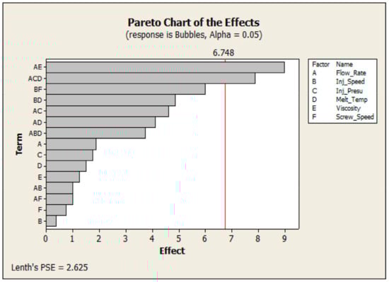
Figure 11.
The significant parameter impact the bubbles appeared.
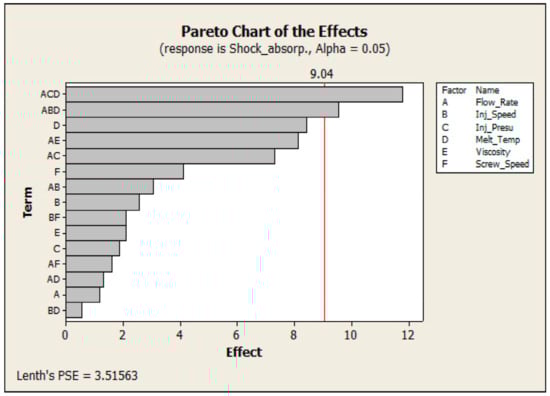
Figure 12.
The significant parameter impact the shock absorbing weakness (durability).
Also, the wrong length dimension defect due to shrinkage, which affected by the injection pressure effected by melting temperature and flow rate, as illustrated in Figure 13, Figure 14 demonstrates that parameters (the magnetic field and # of electrodes) impact mixture properties most. Therefore, the author uses a prediction metaheuristic for on/off Riga surface electrodes to control the magnetic field and sort two alumina sizes (). Also, the Figure points to the viscosity importance affected by thermal conductivity, which receives heat from outsource and inner-source.
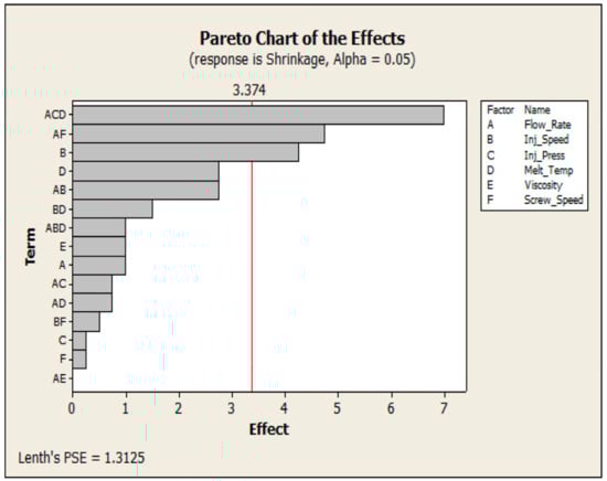
Figure 13.
The significant parameter impact the shrinkage due to wrong length.
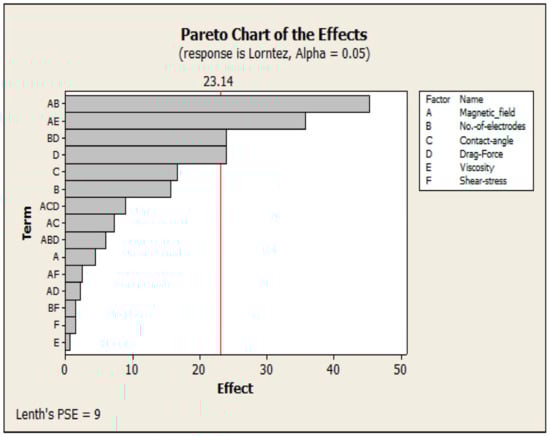
Figure 14.
The significant parameter impact the incubator mechanism.
The analysis of significant parameters to check the impact weight via ANOVA is shown in Table 7. Six working parameters elected were found to be accountable for product properties’ quality flaws and weaknesses based on data analysis and control as discussed above in the pseudocode and enhance the product characteristics. They are injection pressure and up melting temperature. Along with operating conditions, the flow rate and viscosity of molten material are considered.
Table 7.
ANOVA outcomes for working parameters.
The previous four figures emphasize that the melting temperature and viscosity are shared significant parameters that must be controlled continuously because they appeared as significant parameters in the injection process and the incubator parameters mechanism.
Table 7 show the importance of control thaw temperature and injection speed which relies on the screw speed, while the injection pressure tackled by MHD molten β(core) and β [55,56,57]. Figure 15 illustrates the behavior of flow under the influence of the Lorentz force, which may form a vortex leading to increasing β(skin) gathering named β(core) which may be utilized to increase product durability by 98.15%, especially when Lorentz force behaves according to Weibull distribution as the following expression WeibullStdDist (3.736946, 96.0272).
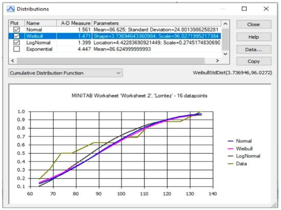
Figure 15.
The Lorentz force effect front Riga surface.
We note from the previous three figures that the mixture’s temperature is a shared influencing factor whose sources must be controlled. The authors found that the heat has an external source that can be controlled, while the internal source depends on the strength of the magnetic field and the number of electrodes installed in a Riga plate. Therefore resorting to the meta-heuristic method help in predicting the relationship between the inner temperature and the electrodes. The DOE showed the interaction effect and emphasized the importance of the main six working parameters because of Prob. >F value as shown in Table 8, which is the basis of the second degrees mathematical model by using Minitab (16) [58,59,60]. Backward elimination is used in this study because it may be used to eliminate unnecessary terms and control the quadratic models for faults. The quality of regression models is demonstrated by the determination of The value of near to 1, that is needed and reasonable concurrence with nearby is essential.
Table 8.
DOE test on design expert.
Figure 16 shows the three main defects, which the authors settled on selected to be eliminated by optimizing process parameters on formed parts and weakening product properties. These defects are mentioned as shrinkage, black dots, and air bubbles, which negatively affect shock absorption durability. Therefore, Figure 17 is interested in analyzing the main parameter that motivates them: the mixture Velocity in the piston and which passes the Riga surface. The F = 3.37 is equal to 0.05 for a level of significant parameters. The Up Melting temperature [F = 8.845 > F = 3.37], injection pressure [F = 7.13 > F = 3.37], and Cooling temperature [F = 2.35 < F = 3.37] have not given a significant effect process variation.
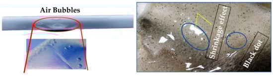
Figure 16.
Defects on the surface of parts.
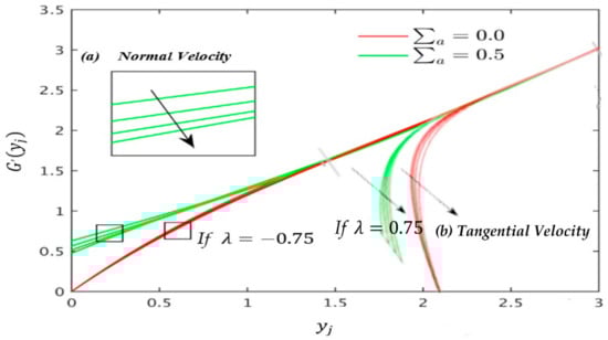
Figure 17.
Normal velocity behavior for and (a) if mixing in flow assisting ; if mixing in flow opposite direction . (b) Tangential velocity behaviour at when : (a) if mixing in flow assisting ; if mixing in flow opposite direction .
The injection speed [F = 7.45 > F = 3.37], and screw speed [F = 6.1 > F = 3.37] have given a significant consequence to the defects rate and up melt temperature having the highest significant value esteems that is 20.45% track by ambient temperature 11.17%, flow rate13.89%, injection pressure 15.6%, and viscosity 11.3% as the influence factor for defects. Cooling time only contributed 0.46%, and lastly, cooling temperature represented 1.85% as illustrated in Figure 16. The cooling temperature and cooling time have no significant effect on the process variation. While Table 9 and Table 10 show the different values of significant variables used to reduce the output vary according to different values of = 0.025, 0.028, 0.031, 0.1 when [61,62]. Figure 18 illustrates the very strong agreement between the existing and available published outcomes. As a result, we are sure that the data presented here are precise/accurate. New analytical research is presented by Aatef D. Hobiny et al. to investigate the effects of heat source velocity on skin tissue temperature [63], while Ibrahim A. Abbas use the Newton-Raphson solver to tackle the non-dimensional governing velocity and temperature contours equations [64].
Table 9.
Numerical values of the point of zero friction factor on the facing surface for dissimilar values of (the case of assisting flow) and velocity slip parameter when and .
Table 10.
Numerical values of the point of zero friction factor on the facing surface for dissimilar values of mixed convection parameter (the case of opposing flow) and velocity slip parameter when and .
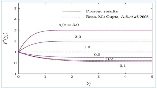
Figure 18.
Comparison of normal velocity pattern for the several values of when [45].
Table 9 and Table 10 show the rate of the of zero resistance factor on the facing surface for some values of and when and , for and , respectively. The location of the point continuously shifts to the left of the origin O (opposing flow region) for a default value of , but further, it shifts to the left of the origin more for the case of the absence of the impact of the velocity slip parameter as compared to the presence of the default value of velocity slip parameter
Figure 19 illustrates the relationship between viscosity (liquid abscission rate) and denisty with time in sec [64]. The converging trend of the goal function discussed in Equation (11) for each test function is shown in Figure 20. The surface quality that have minimum defect opportunities is approximately zero. The IFM system, i.e., RSM integrated with mathematical WSA algorithm, which is considered the theoretical and practical approach, are combined essentially to develop an acceptable functional relationship between the input parameter and the response y relies on precise prediction to defective opportunities appears. Input parameters are symbolized by A, B, C……AC, BC, as expressed in Equation (11). In the current analysis, the thermal dispersion impact across a vertical Riga plate in a fluid-saturated porous media is studied numerically where mimicking Ibrahim A. Abbas et al. [65] in tackling the flow equations, which consider Forchheimer extension.
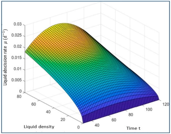
Figure 19.
Contour plots between melt temperature and viscosity.
Figure 20.
Contour plots between Injection Pressure and Melt temperature.
In this study, we have taken up statistical modelling to build a similarity between the response y and independent variables [66].
6. The Validation of the IFM mechanism
The main objective of hybridization is to improve the machining operation by adapting the process quickly to keep the products within the quality standard specification and prevent defect opportunities from appearing, as shown in Table 11. The author tests the validity of the hybridizing of two metaheuristic methods modified by comparing their results of the optimality for working conditions for mathematical WSA in searching for the value lie between LL and UL. The validation follows comparing with thirteen metaheuristic functions tackled [66]. The solution’s fitness is illustrated in Figure 21 for two cases of λ (−0.75, 0.75), and choose the minimum deviation.
Table 11.
Recommended setting of factors.
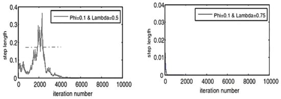
Figure 21.
The fitness values of the best artificial agent vs. iteration number of Rastrigin Problem (RG) because it has minimum deviation.
The Analysis of Results
An improper flow rate of molten material causes air bubbles on the surface of plastic parts. The air bubbles due to the lousy mixture appear due to the die cavity when molten material is injected into the die. The mass flow rate is also responsible for air bubbles in the molded part. Table 10 shows recommended setting for optimum parameters. These results are taken by using Minitab (16). Figure 22 illustrates the difference between DOE and IFM prediction temperature as a significant working parameter. The IFM is superior to the twelve native methods and has equality with the three methods. It reduces the defects through continuous monitoring to guide the process toward adaptive resetting of their working parameters to keep the products within the standard specification, as shown in Table 10. Table 11 shows the factorial design in which four factors are also known as parameters, with two levels selected. This matrix is constructed in design expert software (7.0.0) [67]. This factorial design shows the parameters set for each factor on which responses are obtained. In the 4th column (, , ) express the defects arranged as follows, whole defects before optimization and the expected defects (if implementing the compared method, if implementing the IFM system).
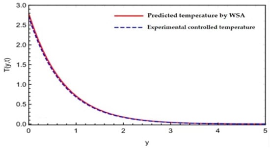
Figure 22.
The comparison between the DOE and IFM temperature of mixture inject by piston (2).
Figure 23 prove the validation of utilizing the mathematical WSA to quick response for desktop injection machine in new modification to rely on it in IFM, as demonstrated through Table 12, which shows the minimum values representing the best choice by shading them. The (, , ) denotes the defects before and after when trying thirteen methods. The injection molding process has improved and reduced defects rate by = (0.9195–0.706/0.85) × 100 = 23.21 % to be by using this optimum setting of factors, as shown in Table 13 and making a comparison before control and after, as shown in Table 14. The IFM system was not superior overall, but the comparison proved that it outperformed in some of the implementation ranges, and the author chose three of them to illustrate the convergent slope according to Equation (10), i.e., the objective function for specific response (bubbles) as illustrated in Figure 22.
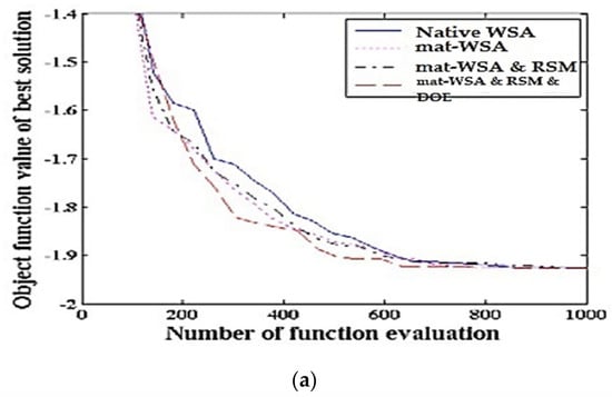
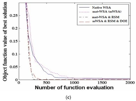
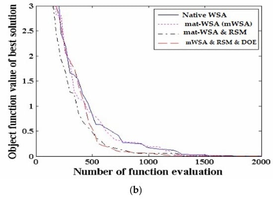
Figure 23.
Convergent slope of the Equation (2) i.e., the objective function for specific response (bubbles). (a) Fourpeak situation function; (b) RosenBrook situation function; (c) Rastrigin situation function.
Table 12.
The comparison of fifteen mechanisms with the proposed IFM simulator to predict the β(+) feed rate via imaging analysis.
Table 13.
Results of Confirmation.
Table 14.
Comparison after and before optimization.
The injection speed [F = 7.45] and screw speed [F = 6.1] have given significant consequences to the defects rate and up melt temperature having the highest significant value esteems that is 20.45% tracked by ambient temperature, while flow rate share, injection pressure, and viscosity 11.17%, 13.89%,15.6%, 11.3% respectively as the influence factor for defects’ reduction. Figure 24 illustrates the optimal working parameters that guarantee to prevent of the three famous defects types with the efficiency of approximately 77.2%, 100%, and 84.23% respectively, while Figure 25 illustrates the durability of the three main famous recycled and notes that the higher the dimensions and the lower the thickness, the lower the durability, but all defects aforementioned in Table 1 are treated. Remaining analysis data can be found in the Supplementary Materials Section.
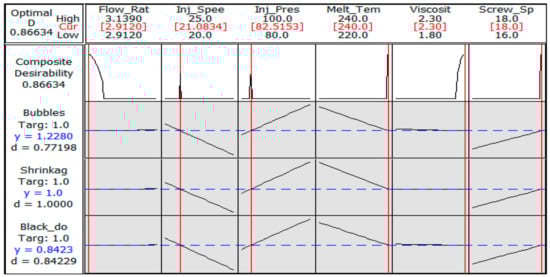
Figure 24.
The optimal working parameters of the IFM for control the common defective opportunity (mixture inside injection machine).
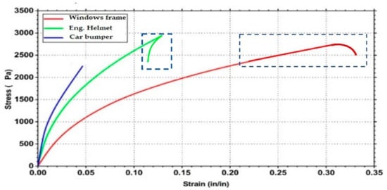
Figure 25.
The durability test for the recycled product for mimic different three product.
7. Case Study Limitations
The experiments declare the importance of controlling the melting temperature, injection pressure, injection speed, and screw speed, as shown in Table 14 and illustrated precisely in Figure 25 and Figure 26. In this work, the integration between the mechanical system that seems evident in the incubator and the automatic control of two components inside, which are the Riga surface and orifice shape of the piston and diameter, to control the alumina density in the mixture and distribute into core and skin by amounts meet the quality of the mixture properties. However, the limitation of the study is that it was implemented experimentally over a small amount of waste, and the ratio of plastic to aluminum is 96.1%:3.9%. When the percentage of alumina is close to 3.9%, the electrodes will be disabled. Therefore, the prediction of imaging analysis must be rapid, which prompted the authors to use the meta-heuristic algorithm as WSA.
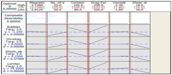
Figure 26.
The optimal working parameters of the IFM system for control the common defective opportunity (mixture inside incubator).
8. Conclusions
Recycling waste is essential, as the results are directly reflected in the environment, especially in recycling heavily polluted material that does not decompose, such as plastics and aluminum cans. The waste characteristics are improved when deciding to recycle to present products with longer lifetimes and the possibility of being reused more than once quickly. The authors worked on using plastic and aluminum waste in the nanoscale size and trying to improve the recycling process by mixing both of them and controlling the operating parameters that ensure the quality of the mixture during the product formation. The authors discover that two significant parameters that affect the RPW qualities are temperature and viscosity 240 , 2.3 respectively, which is set experimentally to disable half electrodes when inner heat is at a maximum value because the solubility is inverse proportion to the amount of heat and magnetic field, as indicated in Table 12. The authors suggest using a meta-heuristic method to control the electricity and related temperature. It was noted that the product’s ability to absorb shocks improved (e.g., car and helmet). Figure 25 and Figure 26 indicate that the injection orifice pressure and viscosity must be controlled to reduce the defects by more than 15.6%. Table 15 shows the improvement after IFM network methodology implementation on the product (e.g., windows frame square cross section) to find shrinkage decreased by 90.4%, while number of shocks increased or durability by 86.6% due to decrease the bubbles in the mixture during forming to 95.7%. The whole process has improved by 90.56%.
Table 15.
Comparison of defective parts after and before improvement.
9. Future Work
There are many applications suggested by the authors that use nanofluid in the power sector by harnessing the maximum heat of the mixture to generate electricity via thermal electric generators TEG to reduce the power consumption by the machine [68].
Supplementary Materials
The following supporting information can be downloaded at: https://www.mdpi.com/article/10.3390/su15032641/s1. Supplementary Materials File S1. Additional source: http://idealstandarddeviati.wixsite.com/leansixsigma.
Author Contributions
Conceptualization, A.M.A. and L.F.S.; Methodology, A.M.A. and L.F.S.; Software, A.M.A. and A.A.; Validation, A.M.A. and S.E.; Formal analysis, A.M.A. and A.A.; Investigation, A.M.A., L.F.S. and S.E.; Resources, A.M.A. and A.A.; Data curation, A.M.A., L.F.S. and S.E.; Writing—original draft, A.M.A. and A.A.; Writing—review & editing, A.M.A. and S.E.; Visualization, A.M.A. and L.F.S.; Supervision, A.M.A. and A.A.; Project administration, A.M.A., L.F.S. and S.E.; Funding acquisition, A.M.A. All authors have read and agreed to the published version of the manuscript.
Funding
This study is supported via funding from Prince Sattam bin Abdulaziz University in Saudi Arabia Project Number (PSAU/2023/R/1444).
Institutional Review Board Statement
Not applicable.
Informed Consent Statement
Not applicable.
Data Availability Statement
Not applicable.
Conflicts of Interest
The authors declare that they have no known competing financial interests or personal relationships that could have appeared to influence the work reported in this paper.
References
- Tanwer, N.; Vashistha, S.; Anand, P.; Khosla, B.; Khosla, B. Plastic Waste Disposal. Plastic Waste Management: Turning Challenges into Opportunities Publisher: Bharti Publications Plastic Waste Management: Turning Challenges into Opportunities, Bharti Publications. 2022. Available online: www.bhartipublications.com (accessed on 29 September 2022).
- Kim, J.K.; Jeon, E.S. Optimization of injection molding process parameters to improve mechanical strength of LFT specimen. Int. J. Appl. Eng. Res. 2017, 12, 3671–3676. [Google Scholar]
- Singh, K.D.; Sharma, R. Three dimensional free convective flow and heat transfer through a porous medium with periodic permeability. Indian J. Pure Appl. Math. 2002, 33, 941–949. [Google Scholar]
- Pal, S.L.; Jana, U.; Manna, P.K.; Mohanta, G.P.; Manavalan, R. Nanoparticle: An Overview of Preparation and Characterization. J. Appl. Pharm. Sci. 2011, 1, 228–234. [Google Scholar]
- Das, S.; Satapathy, A.; Das, J.; Panda, J. Mass transfer effects on MHD flow and heat transfer past a vertical porous plate through a porous medium under oscillatory suction and heat source. Int. J. Heat Mass Transf. 2009, 52, 5962–5969. [Google Scholar] [CrossRef]
- Khan, S.K.; Sanjayanand, E. Viscoelastic boundary layer flow and heat transfer over an exponential stretching sheet. Int. J. Heat Mass Transf. 2005, 48, 1534–1542. [Google Scholar] [CrossRef]
- Postelnicu, A. Influence of a magnetic field on heat and mass transfer by natural convection from vertical surfaces in porous media considering Soret and Dufour effects. Int. J. Heat Mass Transfer. 2004, 47, 1467–1472. [Google Scholar] [CrossRef]
- Kim, Y.J. Unsteady MHD convective heat transfer past a semi-infinite vertical porous moving plate with variable suction. Int. J. Eng. Sci. 2000, 38, 833–845. [Google Scholar] [CrossRef]
- Kumar, D.; Kapoor, A. Optimization of Process Parameters in Injection-Molding by Recent Methods for Optimization—Literature Review. In Proceedings of the National Conference on Sustainable and Emerging Trends In Mechanical Engineering “NCSETME 2018”, Jaipur, India, 28 March 2018. [Google Scholar]
- Abed, S.A.; Khalaf, A.A.; Mnati, H.M.; Hanon, M.M. Optimization of mechanical properties of recycled polyurethane waste microfiller epoxy composites using grey relational analysis and taguchi method. East.-Eur. J. Enterp. Technol. 2022, 1, 48–58. [Google Scholar] [CrossRef]
- Larsen, A.G.; Olafsen, K.; Alcock, B. Determining the PE fraction in recycled PP. Polym. Test. 2021, 96, 107058. [Google Scholar] [CrossRef]
- Zhao, P.; Zhou, H.; Li, Y.; Li, D. Process parameters optimization of injection molding using a fast strip analysis as a surrogate model. Int. J. Adv. Manuf. Technol. 2010, 49, 949–959. [Google Scholar] [CrossRef]
- Xu, Y.; Zhang, Q.; Zhang, W.; Zhang, P. Optimization of injection molding process parameters to improve the mechanical performance of polymer product against impact. Int. J. Adv. Manuf. Technol. 2014, 76, 2199–2208. [Google Scholar] [CrossRef]
- Rajalingam, S.; Vasant, P. Optimization of Injection Molding Process Parameters by Response Surface Methods. J. Inf. Technol. Softw. Eng. 2016, 42, 2047–2061. [Google Scholar] [CrossRef]
- Kavade, M.V. Parameter Optimization of Injection Molding of Polypropylene by using Taguchi Methodology. IOSR J. Mech. Civ. Eng. 2012, 4, 49–58. [Google Scholar] [CrossRef]
- Ajorloo, M.; Ghodrat, M.; Kang, W.-H. Incorporation of Recycled Polypropylene and Fly Ash in Polypropylene-Based Composites for Automotive Applications. J. Polym. Environ. 2020, 29, 1298–1309. [Google Scholar] [CrossRef]
- Strangl, M.; Lok, B.; Breunig, P.; Ortner, E.; Buettner, A. The challenge of deodorizing post-consumer polypropylene packaging: Screening of the effect of washing, color-sorting and heat exposure. Resour. Conserv. Recycl. 2020, 164, 105143. [Google Scholar] [CrossRef]
- Mansur, A.; Mu’Alim; Sunaryo. Plastic Injection Quality Controlling Using the Lean Six Sigma and FMEA Method. IOP Conf. Series Mater. Sci. Eng. 2016, 105, 012006. [Google Scholar] [CrossRef]
- Hidayah, M.H.N.; Shayfull, Z.; Noriman, N.Z.; Fathullah, M.; Norshahira, R.; Miza, A.T.N.A. Optimization of warpage on plastic part by using response surface methodology (RSM). AIP Conf. Proc. 2018, 2030, 020155. [Google Scholar] [CrossRef]
- Zhai, M.; Xie, Y. A study of gate location optimization of plastic injection molding using sequential linear programming. Int. J. Adv. Manuf. Technol. 2009, 49, 97–103. [Google Scholar] [CrossRef]
- Kapadia, D. Shrinkage and Warpage in Polymer Injection Moulding: Models and Simulation. Institute of Polymer Injection Moulding and Process Automation. Master’s Thesis, Universität Linz, Linz, Austria, 2019. [Google Scholar]
- Zuraimi, R.; Sulaiman, M.A.; Mohamad, E.; Ghani, J.A. Tensile strength analysis of high density polyethylene for injection moulded parts. J. Adv. Manuf. Technol. 2017, 11, 151–164. [Google Scholar]
- Timans, W.; Ahaus, K.; Antony, J. Six Sigma methods applied in an injection moulding company. Int. J. Lean Six Sigma 2014, 5, 149–167. [Google Scholar] [CrossRef]
- Shyam, R.; Barode, K.; Jain, S. Improvement in production rate by reducing the defects of injection moulding by DMAIC approach. Int. J. Adv. Res. Ideas Innov. Technol. 2018, 4, 905–908. [Google Scholar]
- Klement, N.; Abdeljaouad, M.A.; Porto, L.; Silva, C. Lot-Sizing and Scheduling for the Plastic Injection Molding Industry—A Hybrid Optimization Approach. Appl. Sci. 2021, 11, 1202. [Google Scholar] [CrossRef]
- Pirc, N.; Bugarin, F.; Schmidt, F.; Mongeau, M. Cooling Channel Optimization for Injection Molding. AIP Conf. Proc. 2007, 908, 525. [Google Scholar] [CrossRef]
- Baum, M.; Jasser, F.; Stricker, M.; Anders, D.; Lake, S. Numerical simulation of the mold filling process and its experimental validation. Int. J. Adv. Manuf. Technol. 2022, 120, 3065–3076. [Google Scholar] [CrossRef]
- Nurcahyo, R.; Rini, L.; Ishak, D.P. Qualtiy improvement in plastic based toy manufacturer using six sigma method. In Proceedings of the International Conference on Industrial Engineering and Operations Management, Kuala Lumpur, Malaysia, 8–10 March 2016; pp. 2634–2643. [Google Scholar]
- Bharara, P. Implementation of DMAIC Methodology for reduction of weighted-defects in a vehicle assembly process. Int. J. Appl. Eng. Res. 2018, 13, 73–80. [Google Scholar]
- Baykasoğlu, A. Optimising cutting conditions for minimising cutting time in multi-pass milling via weighted superposition attraction–repulsion (WSAR) algorithm. Int. J. Prod. Res. 2021, 59, 4633–4648. [Google Scholar] [CrossRef]
- Nguyen, T.T.; Nguyen, T.A.; Trinh, Q.H. Optimization of milling parameters for energy savings and surface quality. Arab J. Sci. Eng. 2020, 45, 9111–9125. [Google Scholar] [CrossRef]
- Han, F.; Li, L.; Cai, W.; Li, C.; Deng, X.; Sutherland, J.W. Parameters optimization considering the trade-off between cutting power and MRR based on Linear Decreasing Particle Swarm Algorithm in milling. J. Clean. Prod. 2020, 262, 121388. [Google Scholar] [CrossRef]
- Baykasoğlu, A.; Akpinar, Ş. Weighted Superposition Attraction (WSA): A swarm intelligence algorithm for optimization problems—Part 2: Constrained optimization. Appl. Soft Comput. 2015, 37, 396–415. [Google Scholar] [CrossRef]
- Kennedy, J.; Eberhart, R. Particle Swarm Optimization. In Proceedings of the ICNN’95—International Conference on Neural Networks, Perth, Australia, 27 November–1 December 1995; Volume 4, pp. 1942–1948. [Google Scholar] [CrossRef]
- Dorrepaal, J.M. An exact solution of the Navier-Stokes equation which describes non-orthogonal stagnation-point flow in two dimensions. J. Fluid Mech. 1986, 163, 141–147. [Google Scholar] [CrossRef]
- Faiz, J.M.; Shayfull, Z.; Nasir, S.M.; Fathullah, M.; Hazwan, M.H.M. Optimisation of process parameters on thin shell part using response surface methodology (RSM) and genetic algorithm (GA). AIP Conf. Proc. 2017, 1885, 020086. [Google Scholar] [CrossRef]
- Stuart, J.T. The Viscous Flow Near a Stagnation Point When the External Flow Has Uniform Vorticity. J. Aerosp. Sci. 1959, 26, 124–125. [Google Scholar] [CrossRef]
- Tamada, K. Two-Dimensional Stagnation-Point Flow Impinging Obliquely on a Plane Wall. J. Phys. Soc. Jpn. 1979, 46, 310–311. [Google Scholar] [CrossRef]
- Khashi’ie, N.S.; Md Arifin, N.; Pop, I. Mixed convective stagnation point flow towards a vertical over Riga surface in hybrid Cu-Al2O3/liquid solution nanofluid. Mathematics 2020, 8, 912. [Google Scholar] [CrossRef]
- Rafique, K.; Alotaibi, H.; Ibrar, N.; Khan, I. Stratified Flow of Micropolar Nanofluid over Riga Plate: Numerical Analysis. Energies 2022, 15, 316. [Google Scholar] [CrossRef]
- Ogungbemi, A.T.; Adun, H.; Adedeji, M.; Kavaz, D.; Dagbasi, M. Does Particle Size in Nanofluid Synthesis Affect Their Performance as Heat Transfer Fluid in Flat Plate Collectors?—An Energy and Exergy Analysis. Sustainability 2022, 14, 10429. [Google Scholar] [CrossRef]
- Mukhopadhyay, S. MHD boundary layer slip flow along a stretching cylinder. Ain Shams Eng. J. 2012, 4, 317–324. [Google Scholar] [CrossRef]
- Xu, L.; Lee, E.W.M. Variational Iteration Method for the Magnetohydrodynamic Flow over a Nonlinear Stretching Sheet. Abstr. Appl. Anal. 2013, 2013, 573782. [Google Scholar] [CrossRef]
- Khan, U.; Zaib, A.; Madhukesh, J.K.; Elattar, S.; Eldin, S.M.; Ishak, A.; Raizah, Z.; Waini, I. Features of Radiative Mixed Convective Heat Transfer on the Slip Flow of Nanofluid Past a Stretching Bended Sheet with Activation Energy and Binary Reaction. Energies 2022, 15, 7613. [Google Scholar] [CrossRef]
- Reza, M.; Gupta, A.S. Steady two-dimensional oblique stagnation-point flow towards a stretching surface. Fluid Dyn. Res. 2005, 37, 334–340. [Google Scholar] [CrossRef]
- Lok, Y.; Pop, I.; Ingham, D.; Amin, N. Mixed convection flow of a micropolar fluid near a non-orthogonal stagnation-point on a stretching vertical sheet. Int. J. Numer. Methods Heat Fluid Flow 2009, 19, 459–483. [Google Scholar] [CrossRef]
- Nadeem, S.; Khan, M.R.; Khan, A.U. MHD oblique stagnation point flow of nanofluid over an oscillatory stretching/shrinking sheet: Existence of dual solutions. Phys. Scr. 2019, 94, 075204. [Google Scholar] [CrossRef]
- Li, X.; Khan, A.U.; Khan, M.R.; Nadeem, S.; Khan, S.U. Oblique Stagnation Point Flow of Nanofluids over Stretching/Shrinking Sheet with Cattaneo–Christov Heat Flux Model: Existence of Dual Solution. Symmetry 2019, 11, 1070. [Google Scholar] [CrossRef]
- Ramachandran, N.; Chen, T.S.; Armaly, B.F. Mixed Convection in Stagnation Flows Adjacent to Vertical Surfaces. J. Heat Transf. 1988, 110, 373–377. [Google Scholar] [CrossRef]
- Haq, R.U.; Sajjad, T.; Usman, M.; Naseem, A. Oblique stagnation point flow of Micropolar nanofluid impinge along a vertical surface via modified Chebyshev Collocation Method. Phys. Fluids 2022, 34, 102001. [Google Scholar] [CrossRef]
- Ogorodnyk, O.; Martinsen, K. Monitoring and Control for Thermoplastics Injection Molding: A Review. Procedia CIRP 2018, 67, 380–385. [Google Scholar] [CrossRef]
- Geem, Z.W. Optimal cost design of water distribution networks using harmony search. Eng. Optim. 2006, 38, 259–277. [Google Scholar] [CrossRef]
- Hahladakis, J.N.; Iacovidou, E. Closing the loop on plastic packaging materials: What is quality and how does it affect their circularity? Sci. Total. Environ. 2018, 630, 1394–1400. [Google Scholar] [CrossRef]
- Souayeh, B.; Bhattacharyya, S.; Hdhiri, N.; Hammami, F.; Yasin, E.; Raju, S.S.K.; Alam, M.W.; Alsheddi, T.; Al Nuwairan, M. Effect of Magnetic Baffles and Magnetic Nanofluid on Thermo-Hydraulic Characteristics of Dimple Mini Channel for Thermal Energy Applications. Sustainability 2022, 14, 10419. [Google Scholar] [CrossRef]
- Zheng, Y.; Gu, F.; Ren, Y.; Hall, P.; Miles, N.J. Improving Mechanical Properties of Recycled Polypropylene-based Composites Using TAGuchi and ANOVA Techniques. Procedia CIRP 2017, 61, 287–292. [Google Scholar] [CrossRef]
- Gholizadeh, S.; Barzegar, A. Shape optimization of structures for frequency constraints by sequential harmony search algorithm. Eng. Optim. 2013, 45, 627–646. [Google Scholar] [CrossRef]
- Khan, U.; Zaib, A.; Ishak, A.; Alotaibi, A.M.; Elattar, S.; Pop, I.; Abed, A.M. Impact of an Induced Magnetic Field on the Stagnation-Point Flow of a Water-Based Graphene Oxide Nanoparticle over a Movable Surface with Homogeneous–Heterogeneous and Chemical Reactions. Magnetochemistry 2022, 8, 155. [Google Scholar] [CrossRef]
- Kalantari, K.R.; Ebrahimnejad, A.; Motameni, H. A fuzzy neural network for web service selection aimed at dynamic software rejuvenation. Turk. J. Electr. Eng. Comput. Sci. 2020, 28, 2718–2734. [Google Scholar] [CrossRef]
- Abed, A.M.; Elattar, S.; Gaafar, T.S.; Alrowais, F. The Neural Network Revamping the Process’s Reliability in Deep Lean via Internet of Things. Processes 2020, 8, 729. [Google Scholar] [CrossRef]
- Abed, A.M.; Seddek, L.F.; AlArjani, A. Enhancing Two-Phase Supply Chain Network Distribution via Three Meta-Heuristic Optimization Algorithms Subsidized by Mathematical Procedures. J. Adv. Manuf. Syst. 2022, 22, 1–32. [Google Scholar] [CrossRef]
- Raza, A.; Khan, U.; Raizah, Z.; Eldin, S.M.; Alotaibi, A.M.; Elattar, S.; Abed, A.M. Numerical and Computational Analysis of Magnetohydrodynamics over an Inclined Plate Induced by Nanofluid with Newtonian Heating via Fractional Approach. Symmetry 2022, 14, 2412. [Google Scholar] [CrossRef]
- Madhukesh, J.; Kumar, R.N.; Khan, U.; Gill, R.; Raizah, Z.; Elattar, S.; Eldin, S.; Shah, S.; Rajappa, B.; Abed, A. Analysis of buoyancy assisting and opposing flows of colloidal mixture of titanium oxide, silver, and aluminium oxide nanoparticles with water due to exponentially stretchable surface. Arab. J. Chem. 2023, 104550. [Google Scholar] [CrossRef]
- Hobiny, A.D.; Abbas, I.A. Theoretical analysis of thermal damages in skin tissue induced by intense moving heat source. Int. J. Heat Mass Transf. 2018, 124, 1011–1014. [Google Scholar] [CrossRef]
- Abbas, I.A.; El-Amin, M.; Salama, A. Effect of thermal dispersion on free convection in a fluid saturated porous medium. Int. J. Heat Fluid Flow 2009, 30, 229–236. [Google Scholar] [CrossRef]
- Raza, A.; Khan, U.; Eldin, S.M.; Alotaibi, A.M.; Elattar, S.; Prasannakumara, B.C.; Akkurt, N.; Abed, A.M. Significance of Free Convection Flow over an Oscillating Inclined Plate Induced by Nanofluid with Porous Medium: The Case of the Prabhakar Fractional Approach. Micromachines 2022, 13, 2019. [Google Scholar] [CrossRef]
- Ghadyanlou, F.; Azari, A.; Vatani, A. Experimental Investigation of Mass Transfer Intensification for CO2 Capture by Environment-Friendly Water Based Nanofluid Solvents in a Rotating Packed Bed. Sustainability 2022, 14, 6559. [Google Scholar] [CrossRef]
- Saeed, T. A Study on Thermoelastic Interaction in a Poroelastic Medium with and without Energy Dissipation. Mathematics 2020, 8, 1286. [Google Scholar] [CrossRef]
- Abed, A.M.; Seddek, L.F.; Elattar, S. Building a Digital Twin Simulator Checking the Effectiveness of TEG-ICE Integration in Reducing Fuel Consumption Using Spatiotemporal Thermal Filming Handled by Neural Network Technique. Processes 2022, 10, 2701. [Google Scholar] [CrossRef]
Disclaimer/Publisher’s Note: The statements, opinions and data contained in all publications are solely those of the individual author(s) and contributor(s) and not of MDPI and/or the editor(s). MDPI and/or the editor(s) disclaim responsibility for any injury to people or property resulting from any ideas, methods, instructions or products referred to in the content. |
© 2023 by the authors. Licensee MDPI, Basel, Switzerland. This article is an open access article distributed under the terms and conditions of the Creative Commons Attribution (CC BY) license (https://creativecommons.org/licenses/by/4.0/).