Abstract
In this paper, an integrated optimization model based on Gradient-Based Optimizer (GBO) for overcurrent relays coordination along with the challenging practical constraints is proposed. The current proposed effort aims to facilitate the coordination strategy and minimize the technical problems facing the protection/site engineers. The objective function is adapted to minimize the total operating time of the primary relays (TOT) concurrently with satisfying a set of constraints. The algorithm endeavors to fine-tune the relay tripping curve to avoid the false tripping in the case of motor starting and/or transformer inrush conditions. Bear in mind that the selected optimized settings should guarantee that the relay would operate in less time than the thermal withstand capability time of the protected equipment. The proposed model is examined over the distribution portion of the Qarun petroleum isolated network (located in West desert/Egypt), which presents a practical test case including some scenarios after validating its performance with the IEEE 15-bus network. The proposed complicated optimization problem comprises 128 discrepant inequality constraints for overcurrent relays coordination only having 16 relays with 14 relay pairs. Eventually, GBO demonstrates that it is an efficient algorithm for solving this highly constrained optimization problem by comparing its performance to other robust and well-known algorithms such as particle swarm optimizer (PSO) and water cycle optimizer (WCA). The performance metrics confirm the GBO’s viability over the others. For sake of quantification, (i) for scenario1 of the Qarun test case, the GBO achieves a TOT of 0.7381 s, which indicates 63% and 57% reductions for those obtained by the PSO and WCA, respectively, and (ii) for the 15-bus test case, reductions in the TOT of 14.3% and 16.5% for scenarios 1 and 2, respectively. The proposed tool based on GBO can enhance the protection co-ordination including some practical constraints.
1. Introduction
Directional Over-Current Relays (DOCRs) can be considered as the primary protection in distribution and sub-transmission systems [1]. The primary relay is responsible for clearing the fault first, and if it fails, the backup one should act after a particular value called the Coordination Time Interval (CTI) [2]. The settings of digital OCRs are mainly the pickup current (), time dial (), and the Time Current Characteristic (TCC) type, which determines the inverse degree of the tripping curve [3]. International Electrotechnical Commission (IEC 60255-3) [4] and IEEE C37.112 [5] define the most commonly used standardized tripping Characteristics (CCs). However, the utilization of nonstandard tripping CCs was proposed in [6] by also optimizing the tripping equation coefficients.
The main objective of the DOCR coordination problem is to minimize the total operating time of the relays in addition to achieving the problem constraints [7]. Previously, it has been solved using conventional techniques such as Linear Programming (LP), Non-Linear Programming (NLP), and Mixed-Integer LP (MILP), as presented in [8]. Moreover, metaheuristic-based algorithms either nature-inspired, swarm-based, or evolutionary-based have been tackled to upgrade the results and the convergence rate [9]. Afterward, hybrid techniques have been implemented such as Cuckoo Search Algorithm and LP in [10] for solving the optimal coordination of DOCRs in microgrids with grid-connected and islanded modes [11]. In this sense, the optimal coordination proposed in [12] complicated the problem by including energy storage systems and inverter-based Distributed Generators (DGs) in the tested networks. The dual-setting DOCR approach was utilized in [13,14,15] for automated distribution networks. The optimal sizing of fault current limiters was investigated to preserve the coordination in the case of DG penetration, as illustrated in [16,17,18].
Various methodologies and formulas of Objective Functions (OFs) have been tackled in the literature, which can be found summarized in [19]. A new approach was discussed in [20] taking into account the topology transient changes using a complete model of all network elements. Various topologies were also discussed in [21] by optimizing the relay-type CCs as in [22] for the microgrid’s optimal protection coordination considering N-1 contingency. However, DOCR coordination was solved using the critical fault point instead of the near-end fault point, as found in [23], which improved the results accuracy. Afterward, active settings of digital OCRs by using the setting group concept were utilized in [24] to be adapted with the current topology of the network. New time–current–voltage CCs in [25] and double-inverse CCs in [26] were proposed to enhance the DOCR coordination in the presence of DGs. Moreover, a modified depth-first search algorithm was proposed in [27], while it was hybridized with MILP in [28] for determining the minimum breakpoint set along with the coordination of OCRs. In this regard, a hybrid variable neighborhood search and LP algorithm was formulated in [29] to cope with diverse DOCRs for online optimal coordination. Furthermore, a stochastic fractal search algorithm was exploited in [30], while the arc flash hazards were assessed along with the optimal OCRs coordination in [31].
This research aims to develop a comprehensive optimization model for OCR coordination integrated with various types of constraints [32,33,34,35,36,37]. These constraints are discrepant in nature, which simulates the real network operating conditions. The objective of this methodology is to minimize the operating time of the primary relays along with satisfying as many of these constraints as possible. Minimum operating time, transient condition, and equipment damage curve constraints represent the main contributions inserted into the optimization model. This highly constrained optimization model is solved through a new optimization approach called Gradient-Based Optimizer (GBO) [32]. It is selected based on the NFL theorem that states that no particular algorithm can solve all optimization problems efficiently. GBO combines the principles of gradient and heuristic-based techniques by enhancing both exploration and exploitation phases [32]. It is worth mentioning that the GBO performance is validated against one of the powerful algorithms for solving power system optimization problems: Slime Mold Algorithm (SMA). Moreover, the GBO results are validated by a fair comparison with other robust algorithms such as Particle Swarm Optimizer (PSO) and Water Cycle Algorithm (WCA).
The main contributions of this work may be summarized as follows: (i) a novel optimization model including practical constrains such as transformer inrush, and motor starting and damage curves are considered, (ii) a novel attempt is made to test the performance of the GBO in solving the OCR problem, and (iii) demonstrations are made on a typical isolated distribution network.
The body of this article is organized into five sections. The formulation of the proposed model is announced in Section 2. Section 3 gives the procedures of the GBO, and the numerical simulations are demonstrated in Section 4 along with various validations. Finally, the findings and concluding remarks are summarized in Section 5.
2. Optimization Model Formulation
The relay operating time can be calculated through (1) by optimizing the relay settings, i.e., (, and type). Table 1 gives the constant values of for various IEC and IEEE CCs. The objective of the OCR coordination problem is to minimize the Total Operating Time (TOT) of the primary relays ( in addition to preserving the problem constraints, as declared in (2). Boundary, selectivity, and operating constraints should be met for achieving feasible results.

Table 1.
Constants for common standardized tripping curves.
2.1. Boundary Constraints
The optimized decision variables should be bounded between lower and upper limits for feasible solution, as shown in (3) and (4).
2.2. Selectivity Constraints
The backup relay should act after a specified period called if the primary relay fails to trip, as shown in (5). The value of is also bounded between the minimum value ( and maximum value ( to restrict the coordination criteria inside a practical time range.
2.3. Operating Constraints
These constraints can be divided into three sets to simulate the real network operating conditions as follows.
2.3.1. Minimum Operating Time Constraint
As the coordination optimization problem tends to minimize the relay operating time, the results may contain an infeasible tripping time not included in any commercial relay. A penalty term is inserted in the OF to guarantee that the relay tripping time is greater than or equal to a specific value , as demonstrated in (6).
2.3.2. Transient Conditions Constraints
It is worth mentioning that induction motors have a starting current range of (3–8) of the motor full load current depending on the starting method and conditions. In this regard, a high inrush current drawn from the supply during transformer energizing has a range of (8–12) for transformer full load current. These transient high currents may lead to a false tripping of the relay during these transient conditions. Figure 1 depicts a typical motor starting curve and a standardized relay tripping CC with the methodology of the practical coordination rules illustrated on it. To avoid the intersection between the two curves, a current margin of (75%) and a time margin () of (2–10) s shall be considered and may be extended to 1 s, as shown. The same practical coordination rules mentioned earlier should also be considered in the case of a transformer overcurrent relay protection feeder, as shown in Figure 2.
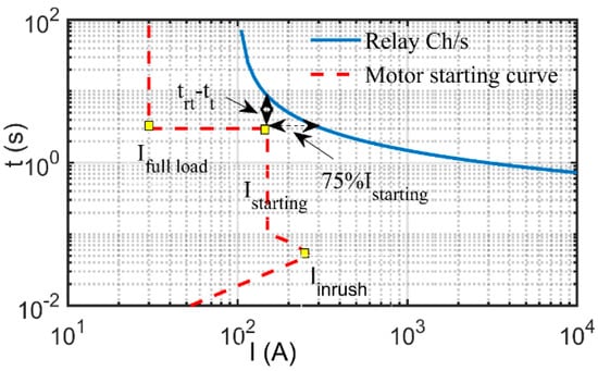
Figure 1.
Motor starting curve with the practical coordination rules.
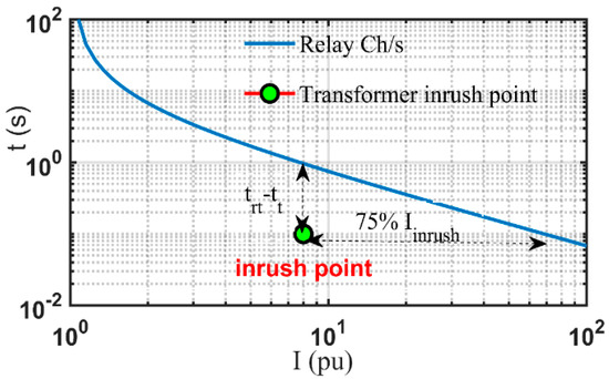
Figure 2.
Transformer inrush point with the practical coordination rules.
Consequently, a penalty term is added to the OF to ensure that the relay tripping curve is higher than the motor starting curve or the transformer inrush point, as expressed in (7). is the relay operating time at the transient current and is the motor starting time or the transformer inrush current period.
2.3.3. Equipment Damage Curves Constraints
All electrical equipment in power systems has a thermal withstand capability curve called a “damage curve”. The damage curve is an inverse relation between the current passing through the equipment and the withstand time. The larger the current that flows , the lower the equipment withstand time . The equipment damage curve can be expressed in (8) where is the Let Through Energy that represents the withstand electrical capability that, in turn, is a constant value. The relation between the fault current passing through a feeder in amperes and for a given Cross-Sectional Area () is shown in (9) [38]. depend on the conductor type, while the initial temperature and the final temperature depend on the insulation type, as declared in Table 2. The constants presented in (9) are lumped together for a single constant , as shown in (10) and depicted in Figure 3, while is in The value of depends on the feeder construction, as declared in Table 2, whose value can be found in [38,39] with a slight difference. The distribution transformers used in this research are classified as category 2, as mentioned in [40], whose constant value equals 1250 per unit.
Table 2.
Feeder constants under various conductor and insulation materials.
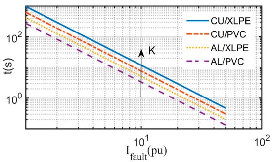
Figure 3.
Cable damage curves with various constructions.
To ensure a safe operation, the relay should trip in less time than the equipment withstand time at the maximum fault point, as shown in (11) and Figure 4. Therefore, a penalty term is added to the OF to satisfy this constraint. It is worth mentioning that there is a conflict of constraints in the optimization model of OCR coordination. This represents a challenging task to the algorithm to pick the optimal settings preserving all these types of constraints. The conflict appears in the algorithm’s attempt to minimize the relay operating time besides positioning the tripping curve above the starting or the inrush curves. Furthermore, the algorithm aims at tripping in less time than the equipment withstand time along with preserving the minimum operating time constraint. Hereinafter, GBO and its behavior concept are discussed in brief in the next section.
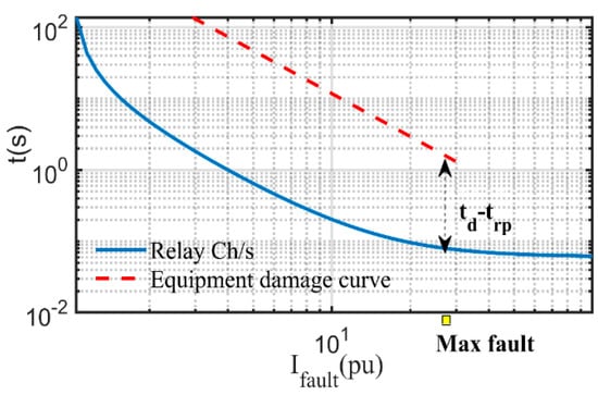
Figure 4.
Equipment damage curve with a standard relay CC.
3. Gradient-Based Optimizer
The optimization techniques can be classified into two main categories based on the optimization behavior process [33,34]. Gradient-based techniques such as Newton’s method estimate the derivatives of the OF along with the constraints by identifying an extreme point whose gradient equals zero. The second category is the non-gradient-based approaches such as all metaheuristic algorithms that randomly generate initial populations, and the optimal solution is attained by updating these search vectors. The GBO combines the principles of the two techniques by enhancing both exploration and exploitation phases. GBO has two main operators: Gradient Search Rule (GSR) that is responsible for enhancing the exploration phase for better convergence in the search agents. The other operator is the Local Escaping Operator (LEO) that prevents GBO from becoming trapped in local minima; more details of the mathematical model of GBO can be found in [32,35,36].
GBO starts with the population initialization by randomly generating the initial vectors according to (12), where is a random number between 0 and 1. represents the solution at iteration n, while and are the boundaries of the decision variable .
GSR is deemed as the main brain of GBO as it controls the vector’s movement and enhances the exploration phase. The Movement of Direction () of the decision variables can be estimated from (13), where is a random parameter assessed from (14). The term expresses the convergence process by moving the current vector into the best vector obtained . The parameter varies with the number of iterations and its value is changed at each iteration, as shown in a figure depicted in [32,36].
As GBO inspires its procedures from Newton’s method, as expressed in (15), the GSR performance is improved by calculating it from (16). is the parameter that balances the exploration and exploitation phases and varies with the parameter .
To promote the efficacy of the proposed algorithm, the LEO is implemented in the subroutine represented briefly in (17) and (18). is a new solution, while is selected randomly over the population and is the newest randomly generated vector. is a binary number that takes a value of 0 or 1 based on the random assessing of other parameters for obtaining the global optimal solution. The relations of the other variables presented in (15)–(18) can be found in detail in [32,36] to avoid making the paper too long. The general procedures of the GBO are depicted in Figure 5 [35,36].
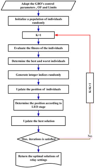
Figure 5.
General procedures of the GBO.
4. Simulation Results and Discussions
The GBO performance is evaluated on two different test cases with various optimization models. The first one is the IEEE 15-bus network that is considered as a test bench tackled by several optimization techniques in the literature. The second one is the medium-voltage distribution portion of the Qarun petroleum company, which is considered an isolated network. New microprocessor-based relays are implemented in both networks coping with continuous decision variables. The limits of are 100% and 150% of the full load current, while the boundaries of are 0.05 s and 1 s, and ranges from 0.2 s to 0.4 s. A of 50 ms is selected as the minimum relay operating time in this research to emulate most of the recent digital relays. The simulation results are executed in the MATLAB environment and implemented using a PC with an AMD A8 processor, 6 GB RAM, and a Windows 10 operating system.
4.1. Test Case 1: IEEE 15-Bus Test Network
To validate the efficacy of the proposed optimization model, GBO performance is examined on the IEEE 15-bus network, which is depicted in Figure 6. This highly penetrated DG network consists of 6 DGs, 21 lines, 42 relays, and 82 Primary/Backup (P/B) relay pairs that are given along with the fault currents in [41]. The optimized settings of DOCRs using the three scenarios are tabulated in Table 3. Scenario 1 achieves a fitness function of 10.2601 s by optimizing 84 decision variables considering the fixed SI tripping curve. In addition, 2.0474 s is the best fitness function obtained by extending the problem to optimize 126 decision variables by selecting the best curve between IEC standardized tripping curves. A fair comparison between GBO and SMA [42] is studied and clarifies that GBO is an efficient optimizer for solving the DOCR coordination. GBO achieves a notable reduction in the total operating time compared to SMA of about 14.3% and 16.5% for scenarios 1 and 2, respectively. In scenario 2, some relays trip in a very small time, which violates the real network conditions. Therefore, the minimum operating time constraints are added to the optimization model in scenario 3, attaining a total time of 2.8198 s. In this context, Table 4 illustrates the operating times of P/B relay pairs and their associated CTI values using the three scenarios. Moreover, GBO attempts all the selectivity constraints in all scenarios with diverse convergence characteristics, as depicted in Figure 7.
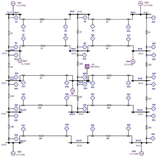
Figure 6.
IEEE 15-bus test network single-line diagram.
Table 3.
DOCRs optimal settings of IEEE 15-bus test network.
Table 4.
Operating times of P/B relay pairs and their associated CTI values of IEEE 15-bus test network.
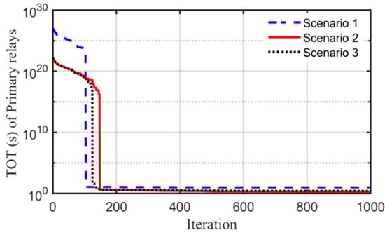
Figure 7.
OF convergence of IEEE 15-bus test network.
4.2. Test Case 2: Qarun Test Network
The single-line diagram of this network is implemented using Electrical Transient Analyzer Program (ETAP) software [43], as shown in Figure 8. This network consists of two 4 MW, 0.8 PF generators connected to a main 3.3 kV sectionalized busbar with a normally open bus coupler. In addition, it consists of eight Dyn11 distribution transformers with an inrush current magnitude of 8 per unit continuing for 100 ms. The starting current of oil-well medium-voltage motors is 5 per unit, continuing for 3 s, and they have a stalling time of 33 s. All cables in this network are CU conductors with XLPE insulation. The system data regarding all elements including generators, transformers, feeders, motors, and MCCs (Motor Control Centers) are given in Appendix A (see Table A1, Table A2, Table A3, Table A4 and Table A5).
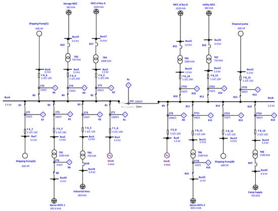
Figure 8.
Qarun test network single-line diagram.
This network consists of 16 OCRS with 14 P/B relay pairs. The symmetrical three-phase and two-phase fault currents are given in Table 5, while the initial load flow currents are given in Table 6. These power system studies are performed using ETAP software considering only the worst-case faults as inputs to the optimization model, i.e., three-phase fault currents. Motors’ starting and stall times are obtained through the manufacturer’s recommendation, while the transformers’ LTE is assumed to be 1250 per unit, according to [35]. The formulation comprises 128 discrepant inequality constraints including 48 constraints related to OCR settings. Furthermore, there are 14 selectivity constraints, 16 minimum operating time constraints, and 24 transient condition constraints. This optimization problem also contains 26 equipment damage curve constraints; 14 of them concern the power cables that are fulfilled by default.
Table 5.
Fault currents passing through P/B relay pairs of Qarun test network.
Table 6.
OCRs optimal settings of Qarun test network.
The proposed optimization model mentioned in Section 2 is run and solved using GBO for this test case with two scenarios. The settings of recent digital relays are optimized with extracting the optimal tripping curve among IEC and IEEE standardized curves, as illustrated in Table 6. Scenario 1 achieves a TOT of 0.7381 s while Scenario 2 achieves a TOT of 1.0387 s with zero boundary and selectivity constraints violations in both scenarios. Table 7 clarifies the operating times of P/B relay pairs, CTI values, and their associated operating constraints for scenario 1. It can be noted that there are six violations in the minimum operating time constraint found in relay pairs 2, 3, 7, 12, 13, and 14. Therefore, the optimization problem becomes more complicated by adding an extra 14 minimum operating time constraints in Scenario 2.
Table 7.
P/B relay pairs operating times and their associated constraint values of Qarun test network for scenario 1.
Scenario 2 achieves better results than Scenario 1 by canceling the violations in the minimum operating time constraint in all pairs except for pair 13. Moreover, the transient condition constraints are improved by expanding the time difference gap, as declared in pairs 2, 4, 5, and 13 and clarified in Table 8. It can be observed that there are no equipment damage curve violations in both scenarios, as declared in Table 7 and Table 8. Pair 13 represents a challenge to the algorithm in bounding the tripping time between of 50 ms and of 124 ms. It is violated in both scenarios by obtaining a very small primary relay tripping time of 20.6 ms in scenario 1 and 27.2 ms in scenario 2. In this context, Figure 9 depicts a TCC sample of a motor feeder with some current time indications, as shown using scenario 2 settings.
Table 8.
P/B relay pairs operating times and their associated constraint values of Qarun test network for scenario 2.
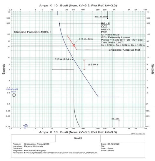
Figure 9.
TCC sample of a motor feeder using scenario 2 settings.
The OF values and statistical measures obtained using GBO, PSO, and WCA are reported in Table 9, while the settings using PSO and WCA are not reported, to avoid making the paper too long. It is clear that GBO achieves a notable reduction in the OF value and better convergence compared to PSO and WCA, as declared in Figure 10 and Figure 11. The data tips shown in these figures are related to the minimum obtained OF value through whole iterations using GBO. There is a slight difference between OF and TOT values due to some violations in the operating constraints, which are multiplied by large factors, as declared in Table 9.
Table 9.
Performance measures of GBO compared to PSO and WCA in Qarun test network.
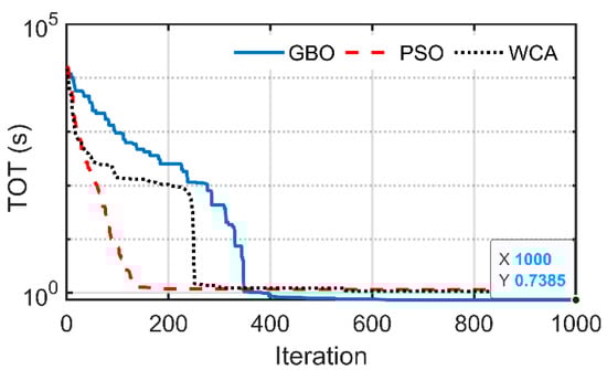
Figure 10.
Scenario 1 OF convergence of Qarun test network.
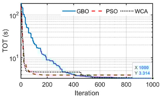
Figure 11.
Scenario 2 OF convergence of Qarun test network.
5. Conclusions
This work represents a forward step in the optimization model of overcurrent relay coordination by solving the practical technical problems facing the protection engineers. This model aims to eliminate the false tripping actions due to energizing inductive equipment such as transformers and motors. Moreover, it is ensured that the OCR will trip before the breakdown of the protected equipment with preserving the minimum operating time condition for each commercial relay. First, the effectiveness of the proposed GBO is interrogated by a fair comparison with SMA for solving the IEEE 15-bus network using various scenarios. In this regard, GBO manifests its superiority by attaining a reduction in the total operating time of 14.3% and 16.5% for scenarios 1 and 2, respectively. Afterward, the proposed optimization model is applied on the medium voltage distribution network of the Qarun petroleum company, which is deemed as an isolated network. GBO achieves a notable reduction in the TOT compared to PSO and WCA with better OF convergence. Moreover, GBO employs the tradeoff technique between the problem constraints with a very low number of violations. Consequently, GBO exhibits only one minimum time constraint violation and zero equipment damage curve constraint violations for Scenario 2. Although scenario 2 complicates the optimization problem, it attains better and feasible results than Scenario 1. Eventually, this model paves the way for researchers to develop and augment the overcurrent relay coordination problem.
Author Contributions
Conceptualization, methodology, software, validation, A.D., M.M.E. and A.E.-F.; formal analysis, A.D.; investigation, data curation, A.D., M.M.E. and A.E.-F.; writing—original draft preparation, A.D.; writing—review and editing; visualization, supervision, M.M.E. and A.E.-F. All authors have read and agreed to the published version of the manuscript.
Funding
This research received no external funding.
Institutional Review Board Statement
Not applicable.
Informed Consent Statement
Not applicable.
Data Availability Statement
All the data have been described in the text.
Conflicts of Interest
The authors declare no conflict of interest.
Appendix A. (Qarun Test Network Data)
Table A1.
Generator data.
Table A1.
Generator data.
| ID | |||
|---|---|---|---|
| Gen A and B | 19 | 28 | 155 |
Table A2.
Transformer data.
Table A2.
Transformer data.
| ID | Rating (kVA) | Impedance (%) |
|---|---|---|
| TR1, 6 | 2500 | 7 |
| TR2, 3, 7 | 750 | 6 |
| TR4, 5 | 2000 | 6 |
| TR8 | 1500 | 6 |
Table A3.
Motor data.
Table A3.
Motor data.
| ID | Rating (HP) | |
|---|---|---|
| Shipping Pumps: (A), (B), (C) | 600 | 103 |
| Disposal Pump | 400 | 71.29 |
Table A4.
Feeder data.
Table A4.
Feeder data.
| ID | Length (m) | Number of Parallel Conductors | |
|---|---|---|---|
| F 1_A | 45 | 240 | 3 |
| F A_2 | 40 | 240 | 1 |
| F A_3 | 180 | 120 | 1 |
| F A_4 | 530 | 240 | 1 |
| F A_5 | 80 | 240 | 2 |
| F A_6 | 800 | 120 | 1 |
| F A_7 | 800 | 120 | 1 |
| F 9_B | 45 | 240 | 3 |
| F B_10 | 45 | 240 | 1 |
| F B_11 | 80 | 240 | 2 |
| F B_12 | 80 | 120 | 1 |
| F B_13 | 800 | 120 | 1 |
| F B_14 | 800 | 120 | 2 |
| F B_15 | 340 | 120 | 1 |
Table A5.
MCC data.
Table A5.
MCC data.
| ID | kW | kVAr | |
|---|---|---|---|
| MCC of Bus A | 0.4 | 867 | 537.3 |
| Industrial Area | 0.4 | 325.5 | 201.8 |
| Storage MCC | 0.4 | 325.5 | 201.8 |
| MCC of Bus B | 0.4 | 867 | 537.3 |
| Utility MCC | 0.4 | 324.7 | 201.2 |
| Camp Supply | 0.4 | 650.3 | 403 |
| Qarun OHTL 1 | 11 | 555.3 | 233.9 |
| Qarun OHTL 2 | 11 | 556.5 | 235.4 |
Abbreviations
| DOCRs | Directional Over-Current Relays | TOT | Total Operating Time |
| CTI | Coordination Time Interval | SI | Standard Inverse |
| TCC | Time Current Characteristic | VI | Very Inverse |
| IEC | International Electrotechnical Commission | EI | Extremely Inverse |
| CCs | Characteristics | LI | Long Inverse |
| LP | Linear Programming | MI | Moderately Inverse |
| NLP | Non-Linear Programming | LTE | Let Through Energy |
| MILP | Mixed Integer Linear Programming | AAC | All Aluminum Conductor |
| CSA | Cuckoo Search Algorithm | ACAR | Aluminum Conductor Alloy Reinforced |
| DGs | Distributed Generators | ACSR | Aluminum Conductor Steel Reinforced |
| OFs | Objective Functions | GSR | Gradient Search Rule |
| GBO | Gradient-Based Optimizer | LEO | Local Escaping Operator |
| SMA | Slime Mold Algorithm | P/B | Primary/Backup |
| PSO | Particle Swarm Optimizer | ETAP | Electrical Transient Analyzer Program |
| WCA | Water Cycle Algorithm | MCCs | Motor Control Centers |
| pickup current | backup relay operating time | ||
| time dial | minimum tripping time of relay | ||
| relay operating time | starting current | ||
| tripping equation constants | relay operating time at the transient current | ||
| fault current | motor starting time or the transformer inrush current period | ||
| relay identifier | equipment withstand time | ||
| relay pair identifier | cross-sectional area | ||
| total number of primary relays | initial temperature | ||
| number of relays subjected to transient conditions constraints | final temperature | ||
| number of relays subjected to equipment damage curve constraints | constant | ||
| relay pairs number | solution at iteration n | ||
| boundaries of the decision variable | |||
| adjusting weighing factors | movement of direction | ||
| , respectively | random parameters | ||
| , respectively | best vector obtained | ||
| minimum value of CTI | the newest randomly generated vector | ||
| maximum value of CTI | binary number | ||
| primary relay operating time |
References
- Albasri, F.A.; Alroomi, A.R.; Talaq, J.H. Optimal Coordination of Directional Overcurrent Relays Using Biogeography-Based Optimization Algorithms. IEEE Trans. Power Deliv. 2015, 30, 1810–1820. [Google Scholar] [CrossRef]
- Alkaran, D.S.; Vatani, M.R.; Sanjari, M.J.; Gharehpetian, G.B.; Naderi, M.S. Optimal overcurrent relay coordination in interconnected networks by using fuzzy-based GA method. IEEE Trans. Smart Grid 2018, 9, 3091–3101. [Google Scholar] [CrossRef] [Green Version]
- Kida, A.A.; Rivas, A.E.L.; Gallego, L.A. An improved simulated annealing–linear programming hybrid algorithm applied to the optimal coordination of directional overcurrent relays. Electr. Power Syst. Res. 2020, 181, 106197. [Google Scholar] [CrossRef]
- IEC 60255; Electrical Relays. Part 3: Single Input Energizing Quantity Measuring Relays with Dependent or Independent Time. Advanced Test Equipment Corporation: San Diego, CA, USA, 1989.
- IEEE C37.112-2018; IEEE Standard for Inverse-Time Characteristics Equations for Overcurrent Relays. Institute of Electrical and Electronics Engineers: Piscataway, NJ, USA, 2019.
- Korashy, A.; Kamel, S.; Alquthami, T.; Jurado, F. Optimal Coordination of Standard and Non-Standard Direction Overcurrent Relays Using an Improved Moth-Flame Optimization. IEEE Access 2020, 8, 87378–87392. [Google Scholar] [CrossRef]
- Papaspiliotopoulos, V.A.; Korres, G.N.; Maratos, N.G. A Novel Quadratically Constrained Quadratic Programming Method for Optimal Coordination of Directional Overcurrent Relays. IEEE Trans. Power Deliv. 2015, 32, 3–10. [Google Scholar] [CrossRef]
- Damchi, Y.; Dolatabadi, M.; Mashhadi, H.R.; Sadeh, J. MILP approach for optimal coordination of directional overcurrent relays in interconnected power systems. Electr. Power Syst. Res. 2018, 158, 267–274. [Google Scholar] [CrossRef]
- Shrivastava, A.; Tripathi, J.M.; Krishan, R.; Parida, S. Optimal Coordination of Overcurrent Relays using Gravitational Search Algorithm with DG Penetration. IEEE Trans. Ind. Appl. 2018, 54, 1155–1165. [Google Scholar] [CrossRef]
- Dehghanpour, E.; Karegar, H.K.; Kheirollahi, R.; Soleymani, T. Optimal Coordination of Directional Overcurrent Relays in Microgrids by Using Cuckoo-Linear Optimization Algorithm and Fault Current Limiter. IEEE Trans. Smart Grid 2016, 9, 1365–1375. [Google Scholar] [CrossRef]
- Sharaf, H.M.; Zeineldin, H.H.; El-Saadany, E.F. Protection Coordination for Microgrids With Grid-Connected and Islanded Capabilities Using Communication Assisted Dual Setting Directional Overcurrent Relays. IEEE Trans. Smart Grid 2016, 9, 143–151. [Google Scholar] [CrossRef]
- Asl, S.A.F.; Gandomkar, M.; Nikoukar, J. Optimal protection coordination in the micro-grid including inverter-based distributed generations and energy storage system with considering grid-connected and islanded modes. Electr. Power Syst. Res. 2020, 184, 106317. [Google Scholar] [CrossRef]
- Yazdaninejadi, A.; Golshannavaz, S.; Nazarpour, D.; Teimourzadeh, S.; Aminifar, F. Dual-Setting Directional Overcurrent Relays for Protecting Automated Distribution Networks. IEEE Trans. Ind. Informatics 2018, 15, 730–740. [Google Scholar] [CrossRef]
- Beder, H.; Mohandes, B.; el Moursi, M.S.; Badran, E.A.; el Saadawi, M.M. A new communication-free dual setting protection coordination of microgrid. IEEE Trans. Power Deliver. 2021, 36, 2446–2458. [Google Scholar] [CrossRef]
- Zeineldin, H.H.; Sharaf, H.M.; Ibrahim, D.; El-Zahab, E.E.-D.A. Optimal Protection Coordination for Meshed Distribution Systems With DG Using Dual Setting Directional Over-Current Relays. IEEE Trans. Smart Grid 2014, 6, 115–123. [Google Scholar] [CrossRef]
- Farzinfar, M.; Jazaeri, M. A novel methodology in optimal setting of directional fault current limiter and protection of the MG. Int. J. Electr. Power Energy Syst. 2019, 116, 105564. [Google Scholar] [CrossRef]
- Elmitwally, A.; Kandil, M.S.; Gouda, E.; Amer, A. Mitigation of DGs Impact on Variable-Topology Meshed Network Protection System by Optimal Fault Current Limiters Considering Overcurrent Relay Coordination. Electr. Power Syst. Res. 2020, 186, 106417. [Google Scholar] [CrossRef]
- Sadeghi, M.H.; Dastfan, A.; Damchi, Y. Optimal coordination of directional overcurrent relays in distribution systems with DGs and FCLs considering voltage sag energy index. Electr. Power Syst. Res. 2020, 191, 106884. [Google Scholar] [CrossRef]
- Draz, A.; Elkholy, M.M.; El-Fergany, A.A. Soft Computing Methods for Attaining the Protective Device Coordination Including Renewable Energies: Review and Prospective. Arch. Comput. Methods Eng. 2021, 28, 4383–4404. [Google Scholar] [CrossRef]
- Mahboubkhah, A.; Talavat, V.; Beiraghi, M. Considering transient state in interconnected networks during fault for coordination of directional overcurrent relays. Electr. Power Syst. Res. 2020, 186, 106413. [Google Scholar] [CrossRef]
- Entekhabi-Nooshabadi, A.M.; Hashemi-Dezaki, H.; Taher, S.A. Optimal microgrid’s protection coordination considering N-1 contingency and optimum relay characteristics. Appl. Soft Comput. 2020, 98, 106741. [Google Scholar] [CrossRef]
- El-Fergany, A.A.; Hasanien, H. Water cycle algorithm for optimal overcurrent relays coordination in electric power systems. Soft Comput. 2019, 23, 12761–12778. [Google Scholar] [CrossRef]
- Alkaran, D.S.; Vatani, M.R.; Sanjari, M.J.; Gharehpetian, G.B.; Yatim, A.H. Overcurrent Relays Coordination in Interconnected Networks Using Accurate Analytical Method and Based on Determination of Fault Critical Point. IEEE Trans. Power Deliv. 2015, 30, 870–877. [Google Scholar] [CrossRef]
- Ojaghi, M.; Mohammadi, V. Use of Clustering to Reduce the Number of Different Setting Groups for Adaptive Coordination of Overcurrent Relays. IEEE Trans. Power Deliv. 2017, 33, 1204–1212. [Google Scholar] [CrossRef]
- Saleh, K.A.; Zeineldin, H.H.; Al-Hinai, A.; El-Saadany, E.F. Optimal Coordination of Directional Overcurrent Relays Using a New Time–Current–Voltage Characteristic. IEEE Trans. Power Deliv. 2014, 30, 537–544. [Google Scholar] [CrossRef]
- Aghdam, T.S.; Karegar, H.K.; Zeineldin, H.H. Optimal Coordination of Double-Inverse Overcurrent Relays for Stable Operation of DGs. IEEE Trans. Ind. Informatics 2018, 15, 183–192. [Google Scholar] [CrossRef]
- Dolatabadi, M.; Damchi, Y. Graph Theory Based Heuristic Approach for Minimum Break Point Set Determination in Large Scale Power Systems. IEEE Trans. Power Deliv. 2019, 34, 963–970. [Google Scholar] [CrossRef]
- Ghotbi-Maleki, M.; Chabanloo, R.M.; Ebadi, M.A.; Savaghebi, M. Determination of optimal breakpoint set of overcurrent relays using modified depth-first search and mixed-integer linear programming. IET Gener. Transm. Distrib. 2020, 14, 5607–5616. [Google Scholar] [CrossRef]
- Damchi, Y.; Dolatabadi, M. Hybrid VNS–LP algorithm for online optimal coordination of directional overcurrent relays. IET Gener. Transm. Distrib. 2020, 14, 5447–5455. [Google Scholar] [CrossRef]
- El-Fergany, A.A.; Hasanien, H.M. Optimized settings of directional overcurrent relays in meshed power networks using stochastic fractal search algorithm. Int. Trans. Electr. Energy Syst. 2017, 27, e2395. [Google Scholar] [CrossRef]
- El-Fergany, A. Optimal directional digital overcurrent relays coordination and arc-flash hazard assessments in meshed networks. Int. Trans. Electr. Energy Syst. 2015, 26, 134–154. [Google Scholar] [CrossRef]
- Ahmadianfar, I.; Bozorg-Haddad, O.; Chu, X. Gradient-based optimizer: A new metaheuristic optimization algorithm. Inf. Sci. 2020, 540, 131–159. [Google Scholar] [CrossRef]
- Mahdinia, S.; Rezaie, M.; Elveny, M.; Ghadimi, N.; Razmjooy, N. Optimization of PEMFC Model Parameters Using Meta-Heuristics. Sustainability 2021, 13, 12771. [Google Scholar] [CrossRef]
- Dehghani, M.; Ghiasi, M.; Niknam, T.; Kavousi-Fard, A.; Shasadeghi, M.; Ghadimi, N.; Taghizadeh-Hesary, F. Blockchain-Based Securing of Data Exchange in a Power Transmission System Considering Congestion Management and Social Welfare. Sustainability 2021, 13, 90. [Google Scholar] [CrossRef]
- Rizk-Allah, R.M.; El-Fergany, A.A. Effective coordination settings for directional overcurrent relay using hybrid Gradient-based optimizer. Appl. Soft Comput. 2021, 112, 107748. [Google Scholar] [CrossRef]
- Eelsayed, S.K.; Agwa, A.; Elattar, E.E.E.; El-Fergany, A. Steady-State Modelling of Pem Fuel Cells Using Gradient-Based Optimizer. DYNA—Ing. Ind. 2021, 96, 520–527. [Google Scholar] [CrossRef]
- El-Kordy, M.; El-Fergany, A.; Gawad, A.F.A. Various Metaheuristic-Based Algorithms for Optimal Relay Coordination: Review and Prospective. Arch. Comput. Methods Eng. 2021, 28, 3621–3629. [Google Scholar] [CrossRef]
- IEEE Std 242-2001; IEEE Recommended Practice for Protection and Coordination of Industrial and Commercial Power Systems. Institute of Electrical and Electronics Engineers: Piscataway, NJ, USA, 2001.
- IEC 60364-4-43; Low Voltage Electrical Installations Part 4-43: Protection for safety-protection against overcurrent. International Electrotechnical Commission: Geneva, Switzerland, 2008.
- IEEE C57.12.01-2015; IEEE Standard for General Requirements for Dry-Type Distribution and Power Transformers. Institute of Electrical and Electronics Engineers: Piscataway, NJ, USA, 2015.
- Alam, M.N.; Das, B.; Pant, V. A comparative study of metaheuristic optimization approaches for directional overcurrent relays coordination. Electr. Power Syst. Res. 2015, 128, 39–52. [Google Scholar] [CrossRef]
- Draz, A.; Elkholy, M.M.; El-Fergany, A.A. Slime mould algorithm constrained by the relay operating time for optimal coordination of directional overcurrent relays using multiple standardized tripping curves. Neural Comput. Appl. 2021, 33, 11875–11887. [Google Scholar] [CrossRef]
- Electrical Power System Analysis & Operation Software. Available online: https://etap.com/ (accessed on 23 December 2021).
Publisher’s Note: MDPI stays neutral with regard to jurisdictional claims in published maps and institutional affiliations. |
© 2022 by the authors. Licensee MDPI, Basel, Switzerland. This article is an open access article distributed under the terms and conditions of the Creative Commons Attribution (CC BY) license (https://creativecommons.org/licenses/by/4.0/).