Abstract
Thermoplastic injection is currently employed in different industrial fields. This process has significantly evolved over the years, and injection machine manufacturers are continuously forced to innovate, to improve the energetic efficiency, aiming to reduce costs, improve competitiveness, and promote environmental sustainability. This work focuses on the development of a novel, profitable, and environmentally friendly plastic over-injection equipment of small metallic parts for the automotive industry, to be applied in a bowden cable production line, to cover the zamak terminations with plastic, or produce terminations entirely made of plastic. The work is based on an over-sized existing solution. The operating parameters required for the work are quantified, and all machine parts are designed separately to achieve the required functionality. Known approaches are finally used to perform the cost analysis, calculate the return on investment (ROI), and energetic efficiency, to substantiate the replacement of the current solution. The new equipment was able to increase the energetic efficiency of the current assembly line while keeping the required injection rates. An efficient and sustainable solution was presented, with a ROI of 1.2 years over the current solution. The proposed design is also applicable to different automated production lines that require this technology. Nowadays, this concept can be extended to all fields of industry that employ injection molding in their processes, enabling to integrate new manufacturing systems, and increasing energetic efficiency while reducing production costs.
1. Introduction
Currently, several industries are using plastic injection molding in their processes, namely thermoplastic injection, including the automotive industry for numerous components such as the bowden cables. Currently, injection molding accounts globally for more than 1/3 of all manufactured plastic parts [1], since it is highly versatile by enabling the fabrication of complex parts including different sizes, shapes, and applications. Furthermore, the fabrication process can be easily set-up for large-scale fabrication and precision engineering. In fact, for most industrial needs, the plastic components can be fabricated in a single-mold and single-shot, thus expediting the process, and enabling design without including sub-components or assembly operations [2]. This process is traditionally divided into four different stages: melting and plasticization of the material, material injection in the mold cavity, in-mold cooling, and part ejection from the mold to finalize the process. Despite the process efficiency, the injection parameters should be carefully set-up, since otherwise low-quality parts will be produced, including deficiencies such as sink marks, voids, short shots, warping, burn marks or jetting [3,4,5]. Currently, as described by Farotti and Natalini [6] and Ardebili et al. [7], the most relevant injection parameters are the injection speed, mold temperature, melt temperature, injection and holding pressures, and cooling setup and time, all affecting important characteristics like the product quality, production rate, surface finishing, and strength. The literature is vast in the analysis and optimization of injection molding parameters and how these affect the injected parts’ microstructure and mechanical properties [6,8,9]. Within the scope of sustainable production, different works focused on environmentally friendly materials, minimum energy consumption, raw material savings, recycling chances and cycle time reduction [10,11,12], leading to an increase of process efficiency and overall competitiveness.
The main purpose of this work is to design a thermoplastic micro over injection molding station to be applied in a bowden cable production line, aiming to increase the environmental sustainability of the fabrication process. These cables can have zamak terminations covered with plastic, or terminations entirely made of plastic, which serve as gripping points to other components, with the final objective of actuating different car systems. These plastic parts of the cables are over-injected using polyethylene, polyamide with or without the addition of glass fibers, and polyacetal. The new equipment should increase the energetic efficiency of the current assembly line while keeping the required injection rates, thus reducing the spent energy in the process for the same output, and reducing production costs, leading to a sustainable solution. Additionally, the equipment should be applicable to different automated production lines which require this technology. To fulfill these goals, the present work focuses on the machine concept, cost analysis, ROI, and energetic efficiency.
2. Literature Review
As an overview of the process, plastic injection molding brings many challenges, both for the equipment designers and respective users (companies), resulting in their need to continuously adapt and innovate to the market demands. The most relevant challenges addressed in the literature are new materials with processing specificities, reuse, use of lighter materials, use of microcellular foaming and nanocomposites, and sustainable production [13]. For instance, Elduque et al. [14] analyzed the environmental impact of plastic injection molding, demonstrating that it strongly depends on the raw material, which showed the need for dedicated studies to accurately evaluate the environmental performance of a specific injection process. To meet the aforementioned demands, specific solutions for these purposes have been made available. To aid the design of injection molding equipment, computer programs, namely computer-aided engineering (CAE) software of computational fluid dynamics, are available to simulate the entire process, optimize the mold design and the injection process itself. For these analyses, it is important to estimate the amount of shear-induced filling and melt imbalances in hot runner systems and multi-cavity molds [15]. If this is not accomplished, then the mold pressures predicted by the software differ from reality. More specifically, the pressure drop in the hot runners will be lower than the real one, since the polymer viscosity will decrease with temperature in the hot runners, but this variation will not be taken into account in the simulations. As a result, these software are not suitable for non-conventional injection molding. A suitable approximation in this case would be to perform the material characterization under non-conventional conditions, i.e., immediately after the material undergoes plasticization in an injection molding machine. As a result, an important step to model the injection process is to characterize the rheological behavior of the polymer [16,17].
The process of thermoplastic injection molding is complex, and it involves significant material transformations (both thermal and structural). In this process, some of the most important requisites are the product quality and repeatability, given that it should be used to continuously produce large batches of parts. As a result, the optimal definition of the process variables acquires a significant importance [18]. Conversely, if these are not carefully defined, the process will result in excessive energy consumption, material waste and scrap parts, thus affecting the companies’ competitiveness and overall sustainability of the process. Thus, continuous process control is required to adapt the process parameters such that high quality parts are consistently obtained. Inclusion of these control systems will ensure the desired repeatability of the whole process, while at the same time almost eliminating variations that can potentially lead to defects and scrapping. Conventional control involves the use of sensors, mold detectors, and infrared spectroscopy. With knowledge on how the process responds to variation to the process parameters, the injection process can be adjusted in real time based on pre-programmed models to produce the desired output, completely automatically and as a result of real time parameter analysis [19]. Because of the criticality of parameter definition in thermoplastic injection molding, in order to achieve the efficiency of the process and high part quality, many studies have dealt with artificial intelligence (AI) techniques to control the fabrication of injected parts and improve the overall process, leading to less waste, less scrap, and optimized energetic efficiency. Ogorodnyk and Martinsen [19] recently performed a detailed review on this matter and identified different models: genetic algorithms [20], artificial neural networks [21], adaptive neural inference systems [22], and others. Owing to the complexity of the thermoplastic injection molding process, the design process of injection equipment is highly complex and requires significant expertise. One important issue during the design is that part cooling before mold ejection can take up to 80% of the total cycle time, which has a significance on the process production rate and product cost [23]. Thus, it is essential to diminish this fabrication step, and different approaches can be considered, as reviewed by Ogorodnyk and Martinsen [19]: application of fast heating/cooling systems based on variotherm technology and using conformal heating and cooling channels. Since these technologies do not compromise the parts’ quality, their joint use with AI control techniques can lead to a significant increase in functionality of the injection manufacturing lines.
The design and efficiency analysis of injection molding equipment (including thermoplastic injection) has been the focus of different researchers, leading to improved efficiency, cost reduction and sustainable processes. Yadav et al. [2] studied the most important parameters and respective influence on thermoplastic injection molding. Conventional mechanical testing and pin-on-disc tests were used to check the influence of both injection and holding pressures on the mechanical and tribological properties of Delrin specimens, respectively. The obtained results showed that higher injection pressures (up to a certain point) increased the specimens’ strength (both tensile and compressive), as well as the wear resistance. On the other hand, the holding pressure had the same effect, but without limit by increasing the pressure for the range of studied values. The work of Baruffi et al. [24] describes and applies the micro-injection molding process (μIM) for thermoplastic elastomers, considering the fabrication of micro suspension rings for sensor applications. The initial stage of the work involved identifying and quantifying the most adequate process parameters, depending on weld-depth measurements and microscopy analysis. Next, the dependence between the values of these parameters on the dimensional characteristics of the rings was addressed. The mold temperature and holding pressure were found to be the parameters with highest influence on the outer ring dimensions. On the other hand, both mold and melt temperatures highly affect the inner ring dimensions. Sharifi et al. [25] evaluated the suitability of freeform injection molding (FIM) in the fabrication of low volume injected molded parts, compared with injection molding. FIM was presented as an innovative method that combines additive manufacturing with injection molding, by using single-use sacrificial closed-cavity mold inserts made from a soluble polymer, which can be fabricated in resin by additive manufacturing. The mold is a block of solidified resin with an internal cavity with the geometry of the desired part. Injection works as a single-shot and the resin strength enables using the process for all thermoplastic resins. The work consisted of evaluating a set of different parts using a science-based approach to test the FIM technique against injection molding. This technique revealed short lead-times, reduced costs, and the typical design flexibility of additive manufacturing, enabling companies to deliver low volume parts faster, with reduced costs and low risk, as well as facilitating product design changes. The work of Enemuoh et al. [26] was motivated by the little knowledge regarding the energy consumption and carbon emissions of fused deposition modeling (FDM) and injection molding. Thus, empirical models were established for the fabrication of polylactic acid dogbone samples by both processes, enabling to perform a critical analysis on the mentioned issues. Injection molding spent approximately 38.2% less energy in fabrication and produced less carbon emissions than FDM. The energy saving of injection molding can be attributed to the shorter cycle time, while FDM involves the product forming phase, leading to higher energy consumption and carbon emissions. As a result, the developed models were recommended for setting and planning production, aiming to achieve sustainable manufacturing.
3. Methodology
3.1. Main Objectives
The present work focuses on the design of a thermoplastic micro over injection molding station, as part of a continuous and automatic production line of bowden cables to be applied in vehicles. An example of a complete cable is presented in Figure 1, showing two main components: the inner cable with the gripping (zamak) terminals, and the protecting outer metallic spiral, involving it for protection during operation in the vehicle. The injection equipment should receive these cables with the two main components assembled, and then either over inject the spiral plastic terminals, or over inject the bowden cable zamak terminations themselves to provide a more suitable link to the components to be actuated (e.g., noise or friction/wear reduction). With the proposed equipment, it will be possible to replace the existing injection machines (from JB Fiser®, Barcelona, Spain) in the automotive component company, which were not specifically sized for the application. Actually, these machines are tailored for larger and heavier parts, thus having much bigger dimensions than necessary, with the corresponding repercussions in the assembly line layout, while the energy consumption is not adjusted to the current standards. Moreover, the proposed over-injection machine design should be adapted to ensure a fast integration in currently running assembly lines of bowden cables production, enabling the increase of efficiency.
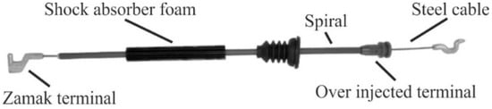
Figure 1.
Example of Bowden cable set for automotive applications.
Thus, to achieve an efficient assembly line with the minimum number of operators, aiming to increase the overall process efficiency, increase the energetic efficiency, and reduce production costs, these outdated machines are to be replaced with smaller, custom-made machines, and tailored for the mentioned operations. This concept was already tested, with good results, with externally acquired injection stations from Babyplast® (Molteno, Italy), whose implementation showed the viability of the process and initiated the transition process towards a more sustainable production. Nonetheless, the end strategy consists of the in-house design and fabrication of a thermoplastic over injection machine that meets the needs, and that can also be applied with little effort into assembly lines for different products in the plant. The motivations to develop an internal design solution for the terminal over injection, assuming beforehand the technical knowledge to build this equipment, are defined as:
- Cost savings due to self-design and fabrication, instead of external acquisition;
- Energy savings arising from a solution specifically tailored to the application, and process sustainability;
- Non-necessity to use the typical consoles equipping by default the commercial solutions, since the microinjection station will be integrated with a control system managing the entire cable production line;
- Non-necessity to buy the hydraulic equipment, standard in the commercial solutions, given that a hydraulic circuit is already available in the factory to feed all equipment. In this scope, only control valves for the hydraulic cylinders are needed;
- Complete knowledge of the equipment, with clear advantages regarding future adaptations to different production rates.
For design purposes, it was necessary to define the component to be over injected, namely concerning the injection volume. Thus, Figure 2 shows the plastic terminal considered for this purpose, used to calculate the injection volume, and required closing force for the mold. This terminal is representative of the components to be injected, and at the top of expectable demands, for both volume mold force. The equated materials by the company for this process are either high-density polyethylene (HDPE), low-density polyethylene (LDPE), polyamide 66 (PA66), or polyoxymethylene/polyacetal (POM). This component has a total injection volume of 1.1483 cm3, and the company targets for a maximum single-part injection time of 6 s, calculated to prevent the machine from serving as bottleneck to the process. In fact, it is considered that the production line can consistently prepare the spiral/cable sets for injection with 6 s intervals, and feed the injector at the same rate.
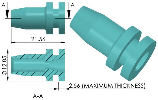
Figure 2.
Sample terminal to be injected by the new machine (A-A represents the cutting plane).
3.2. Current over Injection Solution
Presently, in the company, the terminal over injection process is accomplished using oversized over injection machines by JB Fiser® (model VMCC 80/200) (Figure 3). The setup requires one dedicated operator for each injection station. Additionally, the bowden cables’ fabrication line is not continuous, and the cable fabrication operations are separated, leading to time consumed by the operators to move the product between stations. As previously mentioned, one of the motivations for the present work is to create an integrated production line for bowden cables, like the ones presented by Moreira et al. [27] and Figueiredo et al. [28], and cancel these activities that do not increase added value to the product. In the over injection workstation, each machine is linked to two molds, and the dedicated operator manages the two molds. While one mold is injecting, the operator should remove the over injected cables and place new cables for injection in the other mold. Switching between operations is carried out by side moving the two molds, semi-automatically by manual input from the operator, as shown in Figure 3a. Figure 3b shows the mold details, including the cable and spiral cavities, to inject several parts simultaneously, and the injected terminal cavities, where the molten plastic will be poured into.
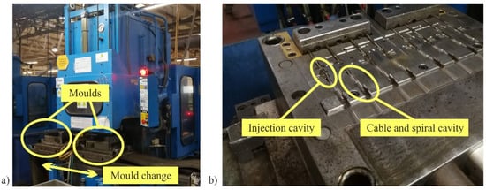
Figure 3.
JB Fiser® injection machine highlighting the mold side movement (a) and single mold detail (b).
Preliminary experiences are undertaken in the company to test micro injection machines from Babyplast® (shown in Figure 4) for over injection of the zamak terminals, aiming to test the idea and serve as a precursor to the application of machine designed in this work. The idea is to test the main concept and part output rate, for subsequent inclusion in bowden cable’s fully automated production lines. The integration of Babyplast® machines is based on two molds: one being injected at the same time the other is being prepared with new parts. Thus, the working principle is similar to the JB Fiser® machines. This integration should be responsible by a significant reduction of energy consumption, as will be discussed further in this work.
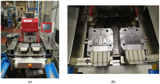
Figure 4.
Zamak terminal over injection in a Babyplast® machine (a) and respective molds (b).
3.3. Company Requisites and Design Assumptions
The current project was requested by an automotive components’ company to increase the efficiency and sustainability of bowden cables’ production lines and, as such, the over injection machine should smoothly incorporate the entire existing process regarding the compatibility and the production rate. As a result, different requisites were established a priori to rule the design process:
- The new machine should be compact, to be incorporated into an existing working line with small disruption, and to promote easy movement inside the shopfloor;
- Ability to process different materials of different sizes (within acceptable limits), and fabrication processes (i.e., possibility to adapt to different working lines or as a standalone equipment;
- Production rate of 6 s (one injected terminal);
- Work with a hydraulic drive;
- Include a heated injection nozzle to prevent the deposition of plastic incrustations on the mold;
- Reduce costs and promote major energy savings, i.e., increase the sustainability, over the current JB Fiser® injection machines working in the plant. The process efficiency should be increased by reducing the current power of the original JB Fiser® machines from 30 kW to a maximum of 10 kW.
Apart from these requisites, design assumptions were provided by the contractor company, regarding the availability of consumables/energy source supply and fabrication restrictions, which are relevant for the equipment design and operation during the injection process:
- The deliverables include the mechanical design of the over injection station, with all construction and operation details, including list of accessories and purchased parts;
- The design includes both sensors and actuators’ selection, while the injection processing and control systems are not required, since the station will be controlled jointly with the other equipment of the production line, considering only one programmable logic controller (PLC). Because of this assumption, the entire electrical project should be externally purchased to a specialized company;
- Injection mold design is not included, since it will be subcontracted to an external company;
- The plant has a built-in hydraulic circuit to supply the over injection station and, thus, the hydraulic circuit supply should not be included. However, the hydraulic cylinder valves should be selected;
- The water-cooling system used to cool the injector is not required as well. The plant provides a general-purpose water circuit (piping system with internal diameter of 20 mm) and a temperature between 18 to 20 °C, with a 3 bar minimum pressure.
4. Design Process
4.1. Final Solution: Equipment’s Representation and Operation
The final design of the assembled over injection machine is represented in Figure 5 and Figure 6, including isometric and side views. The global dimensions of the machine (ready-to-use) are: 2938 mm (height), 1632 mm (length), and 753 mm (width).
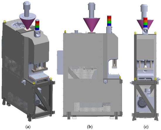
Figure 5.
General representation of the injection machine: isometric (a), side (b) and front views (c).
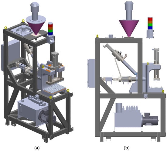
Figure 6.
General representation of the injection machine without the panels: isometric (a) and sides views (b).
All the subsystems that constitute the over injection machine are represented in Figure 7 using an exploded view. A brief description is made in this section to understand the subsystems that compose this equipment, and respective working principle. Further details, including the design solutions, are given in Section 4.3 and Section 4.4 on the three main systems of the machine: press unit, injection unit (divided into extrusion set and injection set), and hydraulic system. The machine’s working principle is described as follows: the mold cavity is fixed into the press subsystem and injected with molten plastic coming from the injection unit, which is composed by the injection and extrusion set, and plasticizes the plastic material. Opening and closing of the mold cavity are operations controlled by the press unit. The base frame, built from welded structural rectangular tubes, aggregates the equipment’s subsystems. The hydraulic group powers the cylinders that perform the desired movements. This equipment was idealized to connect to the client factory hydraulic circuit, but if the client does not have a self-hydraulic circuit or if the equipment is commercialized as ready to use equipment, then a hydraulic group (represented in Figure 7) is used to control the hydraulic cylinders. In order to help the feeding of the equipment with plastic grains and avoid moisture and contamination in the plastic, an automatic vacuum-based feeder system is used, which fills the hopper with plastic, isolating it from the surrounding air. A system of temperature and humidity sensors is included to control an extractor fan that extracts the fumes and hot air from inside the machine and keeps the equipment environment controlled. This type of equipment works with high temperatures and vapors coming from the humidity in the plastic, causing a high probability of fire. Thus, to avoid the spread of fires coming from the equipment and/or alert the factory in such case, a light signal with the machine status and a siren are part of the standard equipment. Protection and enclosure panels are used to make this equipment safe, avoid dust accumulation in vital parts and prevent workers from being injured. Holes in the panels let fresh air come inside the machine to control the environment and keep an acceptable temperature. The electric circuit is managed inside an electric box behind the equipment.
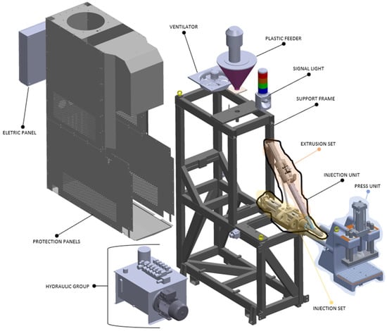
Figure 7.
Over injection equipment and its subsystems.
4.2. Definition of the Operating Parameters
The proposed equipment is complex, and it requires special attention being paid to the operating parameters, to enable smooth production and fabrication of high-quality parts. The most relevant parameters/properties necessary to design this equipment are as follows, and will be discussed separately:
- It is necessary to know the physical properties of the raw materials to produce the parts;
- The number of parts that the machine must inject in a single cycle is necessary to estimate the cooling time of the produced parts;
- The cycle time, maximum volume of injection per cycle and closing force should be estimated.
4.2.1. Physical Properties of the Raw Plastic Materials
The over injection equipment should be able to process different thermoplastic materials with different properties and operating conditions, including processing temperatures and pressures. The necessary product information and physical properties of the plastic materials to be injected by this equipment are shown in Table 1. All these materials are semi-crystalline, and their target extraction temperatures (Tb) are as follows: 50 °C (HDPE and LDPE), 140 °C (PA66), and 150 °C (POM).

Table 1.
Product information and physical properties of the polymers to be used in the injection machine.
All the materials are semi crystalline. The material PA66 has the maximum injection pressure and plasticizing temperature. Thus, these two values are used to design the machine. It is also important to consider that PA66 is more suitable to absorb humidity than the others.
4.2.2. Cooling Time Estimation for the Injected Parts
The cooling time is a relevant process parameter to calculate the cycle time of the machine and guarantee the proper quality of the injected parts. In order to estimate the cooling time of a single part (tk), the Wubken equation was considered, giving tk as
where:
The cooling time of all raw materials is then estimated to identify the maximum tk and establish the cycle time of the machine. On the other hand, the input parameters in the equation were based on the recommended data [29,30], choosing the variable values in a way that the tk estimation would be as high as possible, thus designing the equipment for the worst possible hypothesis. The results of the tk estimation are shown in Table 2. From the obtained results, the maximum tk is 35 s and it corresponds to the material POM.
Table 2.
Cooling time estimation.
4.2.3. Calculation of Cycle Times, Production Rate, and Mold Closing Force
For the calculation of the cycle times, injection production rate and mold closing force, the following requirements/restrictions are known:
- There is a terminal ready to be injected every 6 s;
- Each terminal will take 35 s to cool down;
- The cooling time is independent of the number of parts being injected.
Taking into account the above facts, the maximum number of parts to be injected in a single cycle is calculated to assure that cycle time per part does not exceed 6 s, to avoid the over injection machine being the bottleneck of the process. On the other hand, this design principle minimizes the idle time of the machine and maximizes its efficiency. Equation (2) is used to calculate the closing force [kN] that the press unit must do when the plastic material is injected into the mold cavity [30],
where
- Ap represents the part projected area into the mold separation plane [cm2];
- Pm is the average injection pressure (between 1/3 and 1/5 of the maximum injection pressure).
A spreadsheet was used to calculate the optimal number of parts to be injected in the same cycle. The following conditions were considered:
- A dry cycle of 3 s;
- Injection time of 1 s;
- Maximum tk obtained in Table 2 (35 s);
- Part volume of 1.1483 cm3;
- An Ap of 2.01 cm2;
- A Pm of 1600 bar.
The results of the developed analysis leading to the calculation of the optimal parts per cycle are shown in Table 3.
Table 3.
Cycle time and clamping force calculation.
The obtained results show that the optimal number of parts to be injected in a single injection cycle is 7 parts. This fabrication condition ensures that the cycle time per part (5.57 s) is not above and is immediately behind the 6 s stipulated limit, also implying that the machine will wait 3 s for new parts. Under these conditions, for a single cycle, the total volume of parts is 8.04 cm3, and the closing force in the press unit is nearly 75 kN.
4.3. Subsystems of the Infection Machine
This section details the subsystems of the injection machine, depicted in Figure 7, namely the press unit, the injection unit, which is composed by the extrusion set and the injection set. The hydraulic group is described separately in Section 4.4. Figure 8 shows the press unit along with its components. In order to be able to make the necessary 7.5 tons of force, the press unit has an 8-ton force capacity hydraulic cylinder. To fix the mold halves, two T-slot plates are used. As the machine must withstand high mold closing loads, small misalignments can give rise to non-negligible transversal loads, and since the opening and closing speed of the mold is not significant, four brass bushings were used to guide four hardened shafts. The bushings are equipped with two cleaning seals, preventing dust from entering the friction zones with the shafts, which could damage both the shafts and bushings. Additionally, two hardened shafts are fixed to the rear of the press unit to promote sliding of the injection unit in order to promote the contact between the injection nozzle and the mold. To facilitate the production of the press unit, its structure is made of grey cast iron, minimizing the raw material cost and facilitating the associated milling operations. The highlighted components of Figure 8 are the following: 1–structure of the press; 2–extruder + injector assembly guiding shafts; 3–transportation rings; 4–ejection cylinder; 5–lower mold table with T-slots for mold fixation; 6–upper mold table with T-slots for mold fixation; 7–mold opening base; 8–adapter of cylinder 11 to base 7; 9–graffitied bronze bearing; 10–scrapers to clean dirt particles and dust from columns 12; 11–cylinder to open and close the mold; 12–guiding columns; and 13–bearing cover and housing of the upper scrapers.
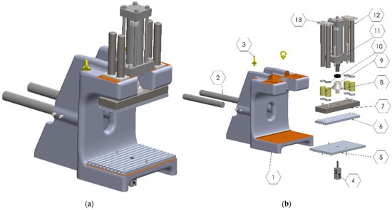
Figure 8.
Press unit: assembled (a) and exploded views (b).
The plastic material is plasticized and injected into the mold by the injection unit. The plasticization of the material is done by the extrusion set and the injection is controlled by the injection set. These two sets constitute the injection unit, represented in Figure 9.
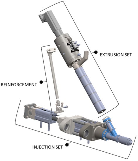
Figure 9.
Injection unit.
The extrusion set (Figure 10) is responsible for molting the plastic material. This set is composed by the plasticizer cylinder and the screw where molting of the plastic takes place, along with its advancement in the extrusion set. This set must avoid the back flow of the plastic material while it is being injected into the mold. Owing to this possibility, a mechanism exists in the power unit that pushes the screw, closing the opening to the injection chamber, thus shutting off the orifice where the plastic material passes to the injection chamber. The main components of the extrusion set are: 1–resistances to heat the plasticizer cylinder; 2–plasticizer cylinder; 3–solid plastic feeding tube; 4–spindle; 5–brass/iron bearing with lubricating oil; 6–spindle motorization part; and 7–electric motor.
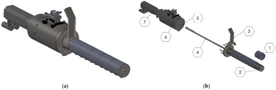
Figure 10.
Extrusion set: assembled (a) and exploded views (b).
The extrusion set uses in its rear a power unit (Figure 11) that provides the torque (to induce screw rotation) and axial load (to advance the screw), in order to plasticize the plastic material and shut-off the screw, preventing the plastic from retracting to the plasticizing cylinder when it is not being injected into the mold. The components that constitute the power unit are as follows: 1–dynamic sealant; 2–lid of cooling assembly; 3–gasket of the cooling assembly, placed between components 2 and 4; 4–body of cooling assembly; 5–nozzles to insert grease into the bearing; 6–temperature sensor; 7–cylinder pushing spindle; 8–cylinder adapter for lever 16; 9–housing body of components; 10–inner locking nut to protect the outer ring of the bearing; 11–four-point angular bearing; 12–bearing support; 13–outer locking nut for tightening of the inner bearing rings; 14–brass bearing; 15–closing shaft that transmits rotation and translation to the spindle; 16–lever; 17–semi brass rings; 18–brass bearing; and 19–adapter to fix the electric motor.
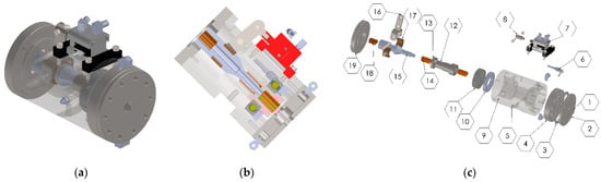
Figure 11.
Extrusion set power unit: assembled (a), cut (b) and exploded views (c).
The injection set (Figure 12) injects the plasticized material into the mold. With this purpose, the injection unit has two hydraulic cylinders, one to inject the plastic itself and another to push the entire injection unit until the injection nozzle contacts the mold. The full set of components depicted in Figure 12 are defined as follows: 1–injection nozzle; 2–electrical resistance to heat the injection chamber; 3–connector between extruder and injector; 4–electrical resistance to heat the flow channel; 5–injection piston; 6–refrigerator assembly cover; 7–inner sealant; 8–scraper; 9–outer seal; 10–polymer bearing; 11–cooling water c supply connection; 12–temperature sensor; 13–body of refrigerator assembly; 14–spacer columns; 15–injection cylinder; 16–backrest cylinder support to the extruder set; 17–pin; 18–backrest cylinder support (16) adapter; 19–backrest cylinder; 20–backrest cylinder mounting adapter; 21–pin; and 22–adapter to attach to the injector structure.
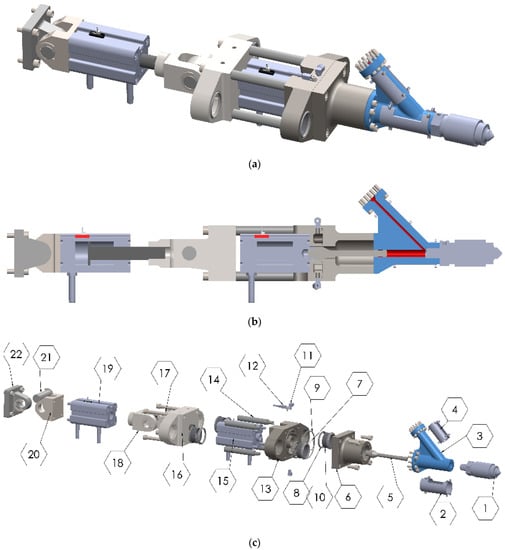
Figure 12.
Injection set: assembled (a), cut (b) and exploded views (c).
4.4. Hydraulic System
The production plant has a hydraulic circuit available at the ground floor to power the equipment. Thus, it is assumed that an oil tank and hydraulic pump are not required. As a result, the current design only deals with the selection of electro valves and respective accessories, and to propose the associated circuit. Figure 13 details the circuit proposal and corresponding control sequence for the injection machine.
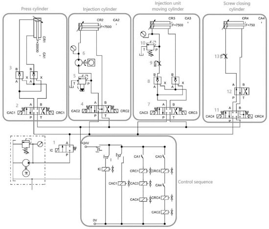
Figure 13.
Hydraulic circuit and control sequence.
The hydraulic pump links directly to a 2/1 normally closed valve (1) that cuts the flow to the machine circuit by default, thus being activated at the time of operation, and also interrupting the flow at the end of operation, when malfunction is detected, or emergency is triggered. The hydraulic circuit is divided into four main cylinder control systems:
- Press cylinder control–Opens and closes the mold;
- Injection cylinder control–Injects the plastic material into the mold cavity;
- Injection unit moving cylinder–Moves the injection unit back and forward;
- Screw closing cylinder–Moves the screw to close the shut off valve.
The four subsystems are described separately next:
- A 4/3 valve (2) controls the cylinder and blocks the oil flow in the stationary position. Since the cylinder cannot fall when it is open, the valve avoids the backflow of the oil in the stationary position. The valve has always some amount of oil leakage, leading to the insertion of a set of one-way valves (3) to ensure that no oil is escaped, avoiding self-closing of the cylinder;
- The injection cylinder must be controlled in velocity and force. With this purpose, a 4/3 proportional valve (4) is employed to control velocity, and an electronic pressure relief valve (5) to control the pressure built in the injection chamber is also applied. A pressure and flow gauge are used to give feedback to the control system. The proportional valve has the cylinder side circuit closed to ensure that only the flow pressure of the plastic produced by the extrusion can back off the injection cylinder, thus avoiding the formation of air pockets in the middle of the plastic melt. This valve has, also, a side that is used to back off the cylinder with the hydraulic pressure to perform maintenance in the machine;
- The controlling setup of the injection unit moving cylinder is similar to the press unit cylinder. Nonetheless, a pressure valve (10) is added to limit the contact force between the injection nozzle and the mold, and to ensure that the maximum allowed force of the injection nozzle (30 kN) is not exceeded. In order to control the velocity of the injection unit movement, flow valves (8) are used to restrict the oil flow;
- The screw closing cylinder is actuated with a 4/3 valve (11), with the cylinder side circuit being normally open to retain the position of the screw. A 4/2 valve (12) is used if the screw becomes stuck or to make maintenance. To control the movement velocity of the cylinder, and also to reduce the impact force of the screw tip, a flow restricting valve (13) is employed.
4.5. Cost Analysis
The calculation of the total budget of the machine is described in this section. The hourly costs of the production processes and the costs per kilogram of the raw material used in the machine components are described in Table 4. The proposed costs were estimated after contacting various companies in the metalworking industry in the factory headquarters’ home country, to reach the best solutions.
Table 4.
Unit costs of required materials and processes.
The detailed calculation of the production cost for all individual components, not described here, was made to obtain a more accurate estimate production cost. This estimate resulted in a production cost of around 10,120 €. Furthermore, the total price of the accessories, like servomotor, hydraulic cylinders, and accessories, resulted in 12,905 €. The total budget of the injection machine is 23,025 €, including the raw materials, fabrication and assembly, specific parts, and standard components.
4.6. ROI and Energetic Efficiency
Aiming to compare the current injection solution, consisting of the oversized JB Fiser® equipment, with a newly designed micro-injector machine similar to the Babyplast® solution, and evaluate the feasibility of replacement in the production line, it becomes necessary to evaluate the injection output and yearly cost of each solution (including energy consumption, material consumption, and maintenance). It should be emphasized that, due to working similarities, the new machine’s characteristics will be equaled to those of the Babyplast® injection machine, whose relevant data was already taken from real productions. The estimation of all related costs is performed for the same injected parts production rate. Currently, according to the company data, the current JB Fiser® machine has a cycle time of approximately 40 s (8 injected parts), which is identical to the Babyplast®. However, since the bottleneck of the process dictates a cycle time of 6 s, the hourly production is considered identical between both cases and approximately 600 parts per hour.
This study will enable to calculate the ROI, essential for the replacement assessment. On the other hand, the spent energy to inject the parts by the two alternatives is also calculated, whose savings by the proposed solution will result in increased efficiency and sustainability of the process. Table 5 initially shows the base features of both equipment, JB Fiser® and Babyplast®, including the in-situ measured daily energy consumption by the company, resulting from a large number of measurements during the production period. An almost ten-fold difference exists, thus anticipating major energy savings over the JB Fiser® machine, since the production rate is identical between the two solutions.
Table 5.
Energy consumption of the JB Fiser® VMCC 80/200 and Babyplast 6/25VP injection machines.
Table 6 presents the necessary data for the ROI and energetic analysis, which was provided by the company based on the historic for the current JB Fiser® machine and Babyplast® (considered equal to the new equipment). The year-based data corresponds to 235 days and 3 eight-hour shifts per day (thus, uninterrupted production of 24 h/day).
Table 6.
Data required for the ROI and energetic analysis.
According to the presented production rate, and considering a 24-h production and 235 days per year, the expected yearly production is approximately 3.38 million parts. An approximation was made to a round number of 3.3 million parts for calculation purposes, leading to a working period of 229.2 days per year and a gap of nearly 6 days plus weekends for maintenance operations. These numbers are valid for both existing and new equipment. By considering 3.3 million parts fabricated/year and the energy consumed, the energy cost was compared between both solutions, showing an 89.9% reduction in both quantities, considering the energy price of 0.1481 €/kWh. The ROI was calculated considering the initial investment for the new solution (equipment and mold cost) and the total yearly costs of both solutions, given by the operation costs added to the energy costs. The operation costs are the sum of raw material waste in setup and start of production, raw material consumption, and maintenance (Table 6). The energy costs are calculated from the energy consumption per hour and energy cost, also given in Table 6. Using this data, the ROI results in 1.2 years, showing that the proposed equipment is a valid replacement for the current solution, leading also to a cheaper and cleaner solution for the injection process, since the energy consumption is highly reduced.
Moreover, it must be highlighted that the current injection machine, as well as the Babyplast® machine, can integrate a more complex production system as idealized by Moreira et al. [27], which can be used under the Industry 4.0 concept, being controlled by a decentralized information system that can also control the logistics around the bowden cables production process, making the manufacturing process more agile and allowing a detailed information about the production in real time.
5. Conclusions
This work aimed to design a thermoplastic over injection station that can increase sustainability and reduce costs in a fabrication line for automotive components (production of bowden cables). The current solution uses over-sized over injection machines whose physical size and energy consumption can be highly improved, leading to the improvement of the company’s competitiveness. A commercial solution is under testing, and the objective is the design of a new equipment that resembles this solution but cancels the need to externally acquire commercial equipment, with the associated higher costs. The estimated production rate of the designed injection machine is a total of seven injected cables in a cycle time of 39 s, which corresponds to 5.57 s per cable end (although the process bottleneck is 6 s). The calculated ROI for the replacement of the old machines was 1.2 years, also showing a major improvement in the energetic efficiency due to an approximate 90% reduction in the energy consumption for identical production rate. Thus, the proposed solution can be used to replace current outdated solutions in companies to keep their production rate, while improving sustainability through the marked reduction in energy consumption. Moreover, new production lines can also be designed using this concept, enabling a design oriented to the proposed concept from the start, with further benefits, and increasing the company’s competitiveness.
In conclusion, with this work, a compact, efficient, and sustainable alternative was presented for over injection of thermoplastic parts for the automotive industry, but that can also be extended to other fields of industry that use identical injection processes in their products, enabling to improve the companies’ competitiveness and present better prices for customers. This over injection machine can also be integrated in more complex production systems, due to its reduced global volume and easy control by other production systems, being completely compatible with the Industry 4.0 concept due to its easy control, contributing by this way to the manufacturing process.
During the development of such works, there is always margin for further improvements. For the designed machine, two main ideas are proposed that can further potentiate its efficiency, although they would require a deep study to analyze their viability:
- In the extrusion set, the use of a cylinder/piston system to plasticize the material, as an alternative to the current cylinder/screw system, could be more efficient and less complex (thus more compact). However, this solution needs thermal simulations and intensive testing to search for the best geometry and reduce cycle times;
- Generally speaking, industrial equipment evolves towards using 100% electrical solutions. These solutions are more efficient, precise, silent and make the equipment more compact. The only downside is its high price due to the complexity of the electrical components. This is another proposal for future work that aims to increase the efficiency of this injection machine, reduce operating noise, and make it more compact.
Author Contributions
Conceptualization, A.L.N.V., R.D.S.G.C. and F.J.G.S.; methodology, R.D.S.G.C. and F.J.G.S.; investigation, A.L.N.V.; supervision: R.D.S.G.C. and F.J.G.S.; formal analysis: R.D.S.G.C., F.J.G.S. and L.P.F.; visualization: L.P.F.; resources: R.D.S.G.C. and L.P.F.; writing original draft: A.L.N.V. and R.D.S.G.C.; writing–reviewing: F.J.G.S. and L.P.F. All authors have read and agreed to the published version of the manuscript.
Funding
This research received no external funding.
Institutional Review Board Statement
Not applicable.
Informed Consent Statement
Not applicable.
Data Availability Statement
Not applicable.
Conflicts of Interest
The authors declare no conflict of interest.
References
- Osswald, T.A.; Hernández-Ortiz, J.P. Polymer Processing: Modelling and Simulation; Hanser: Cincinnati, OH, USA, 2006. [Google Scholar]
- Yadav, R.; Pancharya, A.; Kant, R. Influence of injection and holding pressure on tribological and mechanical behavior of injection moulded thermoplastic. Mater. Today Proc. 2020, 41, 915–920. [Google Scholar] [CrossRef]
- Sreedharan, J.; Jeevanantham, A. Optimization of Injection Molding Process to Minimize Weld-line and Sink-mark Defects Using Taguchi based Grey Relational Analysis. Mater. Today Proc. 2018, 5, 12615–12622. [Google Scholar] [CrossRef]
- Dzulkipli, A.A.; Azuddin, M. Study of the Effects of Injection Molding Parameter on Weld Line Formation. Procedia Eng. 2017, 184, 663–672. [Google Scholar] [CrossRef]
- Singh, G.; Pradhan, M.; Verma, A. Multi Response optimization of injection moulding Process parameters to reduce cycle time and warpage. Mater. Today Proc. 2018, 5, 8398–8405. [Google Scholar] [CrossRef]
- Farotti, E.; Natalini, M. Injection molding. Influence of process parameters on mechanical properties of polypropylene polymer. A first study. Procedia Struct. Integr. 2018, 8, 256–264. [Google Scholar] [CrossRef]
- Ardebili, H.; Zhang, J.; Pecht, M. Encapsulation Technologies for Electronic Applications; William Andrew: New York, NY, USA, 2018. [Google Scholar]
- Ozcelik, B.; Ozbay, A.; Demirbas, E. Influence of injection parameters and mold materials on mechanical properties of ABS in plastic injection molding. Int. Commun. Heat Mass Transf. 2010, 37, 1359–1365. [Google Scholar] [CrossRef]
- Bledzki, A.K.; Faruk, O. Effects of the chemical foaming agents, injection parameters, and melt-flow index on the microstructure and mechanical properties of microcellular injection-molded wood-fiber/polypropylene composites. J. Appl. Polym. Sci. 2005, 97, 1090–1096. [Google Scholar] [CrossRef]
- Tranter, J.B.; Refalo, P.; Rochman, A. Towards sustainable injection molding of ABS plastic products. J. Manuf. Process. 2017, 29, 399–406. [Google Scholar] [CrossRef]
- Vassallo, C.; Rochman, A.; Refalo, P. The impact of polymer selection and recycling on the sustainability of injection moulded parts. Procedia CIRP 2020, 90, 504–509. [Google Scholar] [CrossRef]
- Madan, J.; Mani, M.; Lyons, K.W. Characterizing Energy Consumption of the Injection Molding Process. In Proceedings of the ASME 2013 International Manufacturing Science and Engineering Conference Collocated with the 41st North American Manufacturing Research Conference, Madison, WI, USA, 10–14 June 2013; The American Society of Mechanical Engineers: New York, NY, USA, 2013. [Google Scholar]
- Fernandez, A.; Muniesa, M.; Javierre, C. In-line rheological testing of thermoplastics and a monitored device for an injection moulding machine: Application to raw and recycled polypropylene. Polym. Test. 2014, 33, 107–115. [Google Scholar] [CrossRef]
- Elduque, A.; Javierre, C.; Elduque, D.; Fernández, Á. LCI Databases Sensitivity Analysis of the Environmental Impact of the Injection Molding Process. Sustainability 2015, 7, 3792–3800. [Google Scholar] [CrossRef] [Green Version]
- Beaumont, J.P. Runner and Gating Design Handbook: Tools for Successful Injection Molding; Hanser: Cincinnati, OH, USA, 2019. [Google Scholar]
- Liao, R.; Yu, W.; Zhou, C. Rheological control in foaming polymeric materials: II. Semi-crystalline polymers. Polymer 2010, 51, 6334–6345. [Google Scholar] [CrossRef]
- Tomasko, D.L.; Burley, A.; Feng, L.; Yeh, S.-K.; Miyazono, K.; Nirmal-Kumar, S.; Kusaka, I.; Koelling, K. Development of CO2 for polymer foam applications. J. Supercrit. Fluids 2009, 47, 493–499. [Google Scholar] [CrossRef]
- Zhao, P.; Zhou, H.; He, Y.; Cai, K.; Fu, J. A nondestructive online method for monitoring the injection molding process by collecting and analyzing machine running data. Int. J. Adv. Manuf. Technol. 2014, 72, 765–777. [Google Scholar] [CrossRef]
- Ogorodnyk, O.; Martinsen, K. Monitoring and control for thermoplastics injection molding: A review. Procedia CIRP 2018, 67, 380–385. [Google Scholar] [CrossRef]
- Dang, X.-P. General frameworks for optimization of plastic injection molding process parameters. Simul. Model. Pr. Theory 2014, 41, 15–27. [Google Scholar] [CrossRef]
- Chang, F.-J.; Chang, L.-C.; Huang, H.-L. Real-time recurrent learning neural network for stream-flow forecasting. Hydrol. Process. 2002, 16, 2577–2588. [Google Scholar] [CrossRef]
- Keskin, M.E.; Taylan, D.; Terzi, O. Adaptive neural-based fuzzy inference system (ANFIS) approach for modelling hydrological time series. Hydrol. Sci. J. 2006, 51, 588–598. [Google Scholar] [CrossRef]
- Hopmann, C.; Ressmann, A.; Reiter, M.; Stemmler, S.; Abel, D. A self-optimising injection moulding process with model-based control system parameterisation. Int. J. Comput. Integr. Manuf. 2016, 29, 1190–1199. [Google Scholar] [CrossRef]
- Baruffi, F.; Calaon, M.; Tosello, G. Effects of micro-injection moulding process parameters on accuracy and precision of thermoplastic elastomer micro rings. Precis. Eng. 2018, 51, 353–361. [Google Scholar] [CrossRef] [Green Version]
- Sharifi, E.; Chaudhuri, A.; Waehrens, B.V.; Staal, L.; Farahani, S.D. Assessing the Suitability of Freeform Injection Molding for Low Volume Injection Molded Parts: A Design Science Approach. Sustainability 2021, 13, 1313. [Google Scholar] [CrossRef]
- Enemuoh, E.; Menta, V.; Abutunis, A.; O’Brien, S.; Kaya, L.; Rapinac, J. Energy and Eco-Impact Evaluation of Fused Deposition Modeling and Injection Molding of Polylactic Acid. Sustainability 2021, 13, 1875. [Google Scholar] [CrossRef]
- Moreira, B.; Gouveia, R.M.; Silva, F.; Campilho, R. A Novel Concept of Production and Assembly Processes Integration. Procedia Manuf. 2017, 11, 1385–1395. [Google Scholar] [CrossRef]
- Figueiredo, D.; Silva, F.; Campilho, R.; Silva, A.; Pimentel, C.; Matias, J. A new concept of automated manufacturing process for wire rope terminals. Procedia Manuf. 2020, 51, 431–437. [Google Scholar] [CrossRef]
- Rosato, D.V.; Rosato, M.G. Injection Molding Handbook; Springer Science & Business Media: Berlin/Heidelberg, Germany, 2012. [Google Scholar]
- Crawford, R.J.; Martin, P.J. Plastics Engineering; Butterworth-Heinemann: Burlington, MA, USA, 2020. [Google Scholar]
Publisher’s Note: MDPI stays neutral with regard to jurisdictional claims in published maps and institutional affiliations. |
© 2021 by the authors. Licensee MDPI, Basel, Switzerland. This article is an open access article distributed under the terms and conditions of the Creative Commons Attribution (CC BY) license (https://creativecommons.org/licenses/by/4.0/).