Abstract
The use of different control techniques has become very popular for controlling the performance of grid-connected photovoltaic (PV) systems. Although the proportional-integral (PI) control technique is very popular, there are some difficulties such as less stability, slow dynamic response, low reference tracking capability, and lower output power quality in solar PV applications. In this paper, a robust, fast, and dynamic proportional-integral resonance controller with a harmonic and lead compensator (PIR + HC + LC) is proposed to control the current of a 15-level neutral-point-clamped (NPC) multilevel inverter. The proposed controlled is basically a proportional-integral resonance (PIR) controller with the feedback of a harmonic compensator and a lead compensator. The performance of the proposed controller is analyzed in a MATLAB/Simulink environment. The simulation result represents admirable performance in terms of stability, sudden load change response, fault handling capability, reference tracking capability, and total harmonic distortion (THD) than those of the existing controllers. The responses of the inverter and grid outlets under different conditions are also analyzed. The harmonic compensator decreases the lower order harmonics of grid voltage and current, and the lead compensator provides the phase lead. It is expected that the proposed controller is a dynamic aspirant in the grid-connected PV system.
1. Introduction
In the past few years, the research community has carried out incredible work in the field of applying control techniques to grid-connected renewable energy sources (RESs), where the RES is connected to the grid through a power electronic inverter. Among all RESs, the use of wind farms and solar PV systems has received significant popularity all over the world [1]. The demand for using RESs is increasing due to the changes in the climate and temperature of the Earth by hydrocarbon deposition due to using fossil fuel energy sources such as coal, natural gas, and gasoline [2]. Considering different issues such as availability of a suitable site, power conversion technique, and installation and maintenance cost and complexity, grid-connected solar PV systems are the better choice over the wind farms [3]. The performance of grid-connected PV systems is important, which depends on the harmonious nature of the PV system [4].
In conventional two-level inverter-based systems, there are some issues such as requirement of a large line filter and a high-voltage rating transistor, which make the system bulky and costly. For the direct integration of power from PV to the grid, multilevel inverter (MLI) topologies can play a superior role than the conventional two-level inverter. The capability of running a line filter and transformer less system can reduce the system size to 50–70% [5,6,7]. Among the topologies of MLI, several complications are investigated in cascaded H-bridge (CHB) and flying capacitor (FC) topologies. A large number of issues such as expensive capacitors, complex control to sustain voltage balance, and poor switching efficiency and power transmission are becoming emerging problems in FC topology. In CHB topology, multiple isolated DC sources are required for each cell of the H-bridge, which is not preferable for this troubled voltage control. To overcome these problems, neutral-point-clamped (NPC) topology is used in the grid-connected PV system, which demonstrates little harmonic distortion in grid current and voltage, common DC bus for all phases, controlled reactive power, highly efficient switching frequency, simple control technique etc. [8,9,10,11,12]. However, power quality is is a major issue for heavy and bulky line filter and step-up transformer less direct grid integration systems. Different control techniques such as proportional-integral (PI), proportional resonance (PR), hysteresis control, sliding mode control (SMC), model predictive control (MPC), and fuzzy logic control are being investigated to improve the performance of grid voltage, current, power, and frequency spectrum and minimize the harmonic distortion [13,14,15,16,17,18,19,20,21]. MLIs use various pulse width modulation (PWM) techniques, i.e., space vector PWM (SVPWM) and sinusoidal PWM (SPWM), to achieve switching pulses for the corresponding transistor of the inverter. For a large number of switching devices, the complexity of using SVPWM is increased compared to the SPWM technique. They cannot reduce the lower order harmonics; thus, a control scheme is used to achieve stability of the system [22]. Different types of compensation techniques are used to mitigate the grid voltage, current, and local load harmonics [23,24].
A sliding mode control is studied in [6] for providing maximum power delivery in a cascaded two-level grid-connected inverter. The authors studied active and reactive power flows under different solar irradiances and used the simple PWM technique for simplicity. Although total harmonic distortion (THD) was being measured and reported, the use of a non-linear controller may have introduced algorithmic difficulty. A novel fuzzy logic-based control scheme for three-phase islanded and grid-connected inverters is reported in [13]. This controller demonstrated stable AC output voltage during transient and steady-state responses with load disturbances. Although the control algorithm of fuzzy logic is verified, the control loop of the proposed algorithm is very sensitive to any change in fuzzy step and is difficult to understand. A passivity-based decoupling control scheme is proposed in [14] for a grid-connected T-type neutral-point-clamped (T-NPC) converter, which controls the DC voltage of the inverter. A mathematical model of the control strategy is presented. It utilized direct and indirect control strategies for controlling the voltage and current. However, the performance under a weak grid is not satisfactory. A model predictive controller is presented in [15] for a grid-connected NPC inverter to reduce the common mode voltage components and flow of leakage current to the ground. The performance against different fault conditions is not well presented in the paper. The performance of a Z-source inverter is controlled by a power predictive control scheme in [16]. The controller featured a simple practical implementation, fast dynamic response, and minimal tracking error for decoupled active and reactive power control. The paper shows the steady-state error and transient response of the proposed controller but the load change effect and fault handling capability are not well described. Yang Han et al. in [17] present a synchronous reference-based proportional-integral controller for a single-phase grid-connected MLI. It represents the influence of the phased-lock loop (PLL) on the grid performance and the steady-state and dynamic responses of the controller. It investigates an improved stability criterion to measure the stability of the system. The frequency responses of grid voltage and current are not investigated in this paper. To mitigate the harmonic distortion in the grid voltage and current, a decentralized control strategy is reported in [18]. This is based on a harmonic compensation scheme, but the performance of transient response, steady-state response, and load change effect is not presented in this paper. The differences between various types of controllers and modulation techniques of inverters for microgrid and industrial applications are presented in [19,20]. An MPC controller with a grid-connected three-level NPC converter is proposed in [25] to provide a robust dynamic response. An adaptive proportional-integral controller is presented in a grid-connected system for capacitor voltage balancing and providing maximum PV power and voltage in [26]. It operates in conjunction with the dq-axes, and comprehensive mathematical expressions are investigated for the design of a controller and the adjacency of control parameters based on maximum PV power, PV voltage, and modulation index for achieving a speedy dynamic response. The grid voltage performance under various irradiances is considered in the work. A model predictive control technique is considered to obtain a robust dynamic response in [27]. Use of non-linear controller and space vector modulation (SVM) schemes introduces system difficulty. In [28], a second-order resonant controller with a lead compensator (SORC + LC) is investigated to control the voltage and provide better performance of transient response, fault-handling capability in different load conditions, and steady-state response for single-phase islanded microgrid. The performance of the three-phase inverter is not investigated and the voltage control-based controller introduces some complexity. An adaptive proportional resonance controller with a frequency-locked loop (FLL) was proposed for synchronizing converters [29]. The technique requires a large filter which makes the system bulky. Moreover, the technique was not investigated for MLI topologies. To design the control scheme of a grid-connected inverter system, the characteristics of suppressing voltage and current oscillation, decreasing THD, reference tracking capability, fault-handling capability, and better transient and steady-state responses are being focused on in different works.
This paper proposes a new control technique for the grid-connected multilevel inverter. The contributions of this paper are:
- A robust and dynamic control scheme for a 15-level (15-L) NPC inverter-fed grid-connected system, which is proposed to improve the system performance;
- The control scheme consists of a proportional-integral resonance (PIR) controller with the feedback of a harmonic compensator (HC) and a lead compensator (LC);
- The harmonic compensator decreases the lower order harmonics of grid voltage and current and the lead compensator provides the addition of phase by increasing the system bandwidth;
- Injected power quality, ability to handle sudden load changes, fault-handling capacity, steady-state response, and stability of the system with the proposed control scheme are investigated to validate the auspicious performance of the controller compared with existing solutions.
The paper is organized as follows: A system description and modelling are described in Section 2; the design of the proposed PIR + HC + LC control scheme is described in Section 3; the performance evaluation of the proposed grid-connected controller and the result analysis and comparison of the performances among controllers are analyzed in Section 4; and finally, the conclusion of the paper is in Section 5.
2. System Description and Modelling
2.1. System Specification and Description
An overall block diagram of the grid-connected PV system is presented in Figure 1. It describes the power flow from the PV array to the grid with the proposed PIR + HC + LC controller. The output parameters of the PV array are being controlled by a DC–DC converter. The switching pulses of this converter are generated from the duty cycle to control the DC–DC converter. The duty cycle is propagated from the maximum power point tracking (MPPT) controller, which utilizes the PV voltage and current. The DC–DC converter offers uniform DC-link voltage to the grid-tied NPC converter. For medium-voltage grid applications, the NPC converter is an excellent choice due to its superiority in handling medium voltage with low-rated semiconductor devices. In this paper, a 15-L NPC converter is considered, which contains 28 transistors on each phase in a three-phase system. An LC filter is used to eliminate the harmonics which are generated from the high-frequency inverter.
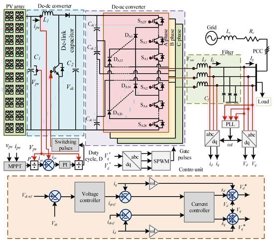
Figure 1.
Block diagram of the grid-tied photovoltaic (PV) system with the proposed proportional-integral resonance controller with a harmonic and lead compensator (PIR + HC + LC controller).
In this closed-loop system, the reference signal is generated by the controller. This supports the inverter by providing gate pulses for the switching device of the controller. The gate pulses are produced by dq-to-abc transformation and the sinusoidal pulse width modulation (SPWM) technique. It is also used to control the current for ensuring the power quality and the stability of the system. In the control section, is calculated from the outer voltage controller by utilizing the DC-link voltage and the reference voltage. Then, is set to zero for unity power factor in the system operation. The errors of the direct axis component ( and ) and the quadrature axis component ( and ) are determined in the control unit. Here, id and iq are used for calculating the errors. By controlling the errors through current controller, the dq components are generated and transformed to abc components for generating the gate pulses. The design parameters of the system are indexed in Table 1.

Table 1.
System specification.
2.2. Power Flow Theory
Figure 2 depicts the power flow theory between two AC sources, which are represented as PV and grid to understand the power flow between the PV source and the grid in a grid-tied system. The power sources are coupled with an impedance of .
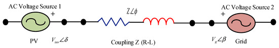
Figure 2.
Power flow analogy.
The power flows from source 1 to source 2 through the Z coupling. The current flow is represented as:
where source 1 is identified as and source 2 is identified as ; Vinv represents the inverter voltage, Vg represents the grid voltage and the angle represents phase reference.
Using , the following can be considered:
In (4), if phase is taken as a reference, i.e., , and .
Then, the active power P can be calculated as:
In (5), if the phase is taken as a reference, i.e., , the reactive power can be calculated as:
From the theory, the real power mainly depends on and the reactive power mainly depends on the rms voltage of the source, .
2.3. System Modelling
The voltage and current of a grid-tied inverter can be controlled by a standard controller which works robustly/fiercely on DC quantities of the inverter current and . The transformation of sinusoidal or alternating output voltage or current to DC quantities, that means abc frame to dq frame, is very expedient in the control technique. The transformation is based on two steps: (a) abc frame to frame by using the Clarke transformation and (b) frame to dq frame by means of the Park transformation [28].
The three-phase output voltage of the inverter is depicted as follows:
where A is the amplitude of the voltage; is the angular frequency; and , , and are the inverter voltages of phases A, B, and C, respectively.
For the three-phase system, the grid voltage equation is depicted as:
where L is the inductance; R is the resistance; i is the inverter current of each phase a, b, and c, and v is the grid voltage of each phase a, b, and c.
From the Clarke transformation:
From the Park transformation:
Now,
The grid and inverter voltages of the dq frame are derived as [28]:
The differential equation of the dq component is given as:
This equation demonstrates that the direct axis and quadrature axis currents are dependent.
2.4. Grid Synchronization
For direct integration of power into the grid from renewable energy sources, power converters play a significant role in interfacing the grid and the renewable generation unit and producing quality power to feed the grid. It is necessary for the grid-tied inverter system to measure the grid voltage phase angle precisely to control the inverter voltage and current. It is also necessary to synchronize the inverter voltage amplitude and frequency with the grid voltage amplitude and frequency. At the point of common coupling (PCC), the inverter and the grid are being synchronized by proper matching of the voltage amplitude and frequency of the grid and the inverter. For simple implementation and exact determination of amplitude and phase, the synchronous reference (d-q)-based phase-locked loop (PLL) is widely used in three-phase grid-connected inverters. It measures the voltage amplitude, phase angle, and frequency of the grid and the inverter, utilizing them for grid synchronization. The control technique of the grid-tied inverter relies on the grid synchronization technique. If the estimated angle is , then the a-b-c to d-q transformation can be given as [30]:
After reducing the equations:
For ideal grid conditions, the determined phase angle () is equal to the phase angle of the grid () while vq is equal to zero. When () is small or close to zero, then the term can be linearized for controlling using the PI controller.
For a balanced three-phase system, the q axis component is close to zero when the PLL angle is locked. In the PLL circuit, the q axis property is denoted as the phase detector (PD). It uses the low-pass filter or the PI controller to decrease the steady-state error. By utilizing the output, a voltage-controlled oscillator (VCO) generates the angle and sine wave. The transfer function of the PLL circuit is given by:
3. Proposed Controller
The main objective of the control technique is to provide maximum power from the NPC converter to the grid. For this purpose, the PV array voltage is controlled by MPPT and the PI controller for providing the maximum constant voltage at the input side. For supplying the maximum power and for generating the sinusoidal output voltage and current, separate voltage and current controllers are used in this system. Figure 3 shows the overall block diagram of the control unit which is used in this system. It represents the outer voltage controller and the inner current controller.
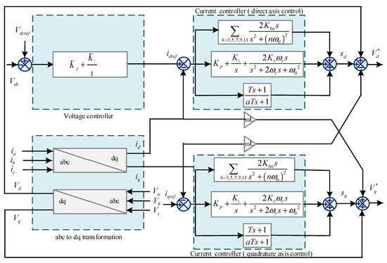
Figure 3.
Block diagram of the control technique including outer voltage controller and internal current controller.
Oscillation in grid voltage and current may cause an unstable power system. It causes high THD of the system. To mitigate oscillation of the system, a new robust and dynamic current control technique is proposed in this paper. It consists of a proportional-integral resonance (PIR) controller with the feedback of a harmonic compensator (HC) and a lead compensator (LC), named as the PIR + HC + LC controller. The PIR controller provides high current ripple, less oscillation, and improved power quality while the HC decreases the lower order harmonics and the LC adds phase lead by increasing the reference tracking ability. The transfer function of this controller is derived as:
where , , > 0. The stability of the system is dependent on the appropriate value of the constant. The controller provides the reference signal which is used to generate the gate pulses for the NPC converter. The gate pulses operate the switching device of the converter to produce the maximum output voltage and current. Here, the outer voltage controller and the inner current controller are used to controlling the system. In the outer controller, the DC-link voltage of the system is compared with the reference DC voltage to estimate the error voltage. By utilizing and controlling the voltage, we obtain the reference current of the direct axis component and also increase the reference tracking capability. By controlling the error of the direct axis component and quadrature axis component using the inner current controller, the duty signal is provided to generate the reference signal. To achieve the maximum power point tracking (MPPT) for the DC-DC converter, it follows the algorithm as:
The reference current is achieved from the output of the MPPT controller and the voltage of PV, and then, it is compared with the PV current and the error is determined. The error is utilized in the PI controller for generating the duty cycle and gate pulses for the DC-DC converter.
Figure 4 depicts the Bode diagram of the proposed current controller. The transfer function represents the frequency response of a circuit. The Bode plot is the graph of frequency and phase versus frequency response of any transfer function. The plot can be obtained from MATLAB. It provides information on the influence of frequency response on changing the circuit components.
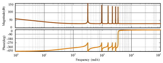
Figure 4.
Frequency spectrum of the current controller in terms of magnitude (db) and phase (deg).
4. Performance Evaluation of the Proposed Controller
The performance of the proposed PIR + HC + LC controller was observed in the MATLAB/Simulink environment for 15-L NPC inverter-fed grid-tied PV system. The stability, dynamic response, sudden load change effect, steady-state response, fault condition analysis, and the frequency spectrum for the system using the proposed controller were evaluated through simulation in MATLAB software. The detailed phenomena of the performance evaluation of the system are described in the following sections.
4.1. Inverter Performance
Figure 5 shows the 15-L NPC inverter performance in the proposed grid-connected PV system with a high-performance controller. The performance was evaluated in two terms, with and without applying the filter circuit to eliminate the harmonics. Here, a second-order LC filter was used in the simulation to minimize the THD of the inverter voltage and current. The inverter voltage and the THD (shown in the frequency spectrum graph) of the voltage without applying the filter circuit are shown in Figure 5a,b, respectively. Without applying the filter circuit, the inverter current and corresponding THD are shown in Figure 5c,d, respectively. Figure 5e–h demonstrate the inverter performance with the filter. These represent the inverter voltage, the frequency spectrum of the voltage, the inverter current, and the THD of the current, respectively. After applying the filter circuit, the oscillation in the voltage and current of the inverter output is minimized. Before applying the filtering circuit, the THD of the inverter voltage was measured at 6.02% and the current THD was measured at 6.00%. After applying the filter circuit, both THDs of voltage and current were minimized and indicated a THD of 5.39% and 2.94% for voltage and current, respectively.
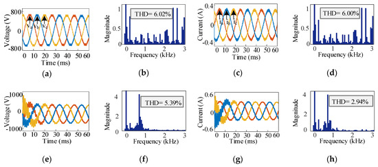
Figure 5.
Inverter performance: (a) inverter output voltage, (b) frequency spectrum of the voltage without filter, (c) inverter output current, (d) frequency spectrum of the current without filter, (e) inverter voltage, (f) frequency spectrum of the voltage with filter, (g) inverter current and (h) frequency spectrum of the current with filter.
4.2. PV Performance
The PV array is directly connected to the grid through the DC-DC converter and the DC-AC converter. The output of different phases in the system is named as the PV performance. Figure 6a denotes the current versus voltage curve of the PV array. It is represented for only one cell of the array. It is observed in different heat conditions of the sun. The power versus voltage characteristics are also shown in Figure 6b and are observed in the same manner. These characteristics curves were obtained by measuring the voltage, current, and power for one PV cell under different solar irradiance conditions. Figure 6c represents the DC-link voltage of the converter. It is the output of the DC-DC converter and the input of the NPC converter. It indicates that the input of the NPC converter is 800 V. The system provides a constant DC-link voltage through MPPT and the control algorithm. The maximum power of the PV array is cracked by the MPPT controller and it helps to generate the constant DC output voltage of the DC to DC converter. Finally, the output power which is directly fed to the grid is shown in Figure 6d. It can be observed from the grid voltage and current. By calculating the voltage and current, the output power can be displayed.
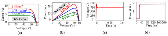
Figure 6.
PV array performance: (a) current–voltage (I-V) characteristics for the PV array in different heatstroke conditions using one cell; (b) power–voltage (P-V) characteristics for the PV array in different heatstroke conditions using one cell; (c) DC link voltage supplied by the PV array through the maximum power point tracking (MPPT) controller for the neutral-point-clamped (NPC) converter, and (d) the output power which is fed to the utility grid.
4.3. Grid Performance
In the grid-tied inverter system, the output grid voltage and current performance with the minimum oscillation are very challenging. Figure 7 depicts the grid performance in terms of voltage and current. The grid voltage is represented in Figure 7a. From the figure, it can be seen that there is no oscillation in the grid voltage and it is sinusoidal. In Figure 7b, the output current is displayed. It shows oscillation in the first cycle of the output current and then the current is almost sinusoidal. Oscillation occurs for the load of the system. For using the current controlled controller, it affects the grid current, and the grid voltage is distortion less. This is a grid-tied inverter where the grid also acts as a source. This is another reason for the sinusoidal voltage and the distorted current. A THD of 0.55%, 0.57%, and 0.58% is observed for phases A, B, and C, respectively. In Figure 7c, the phase difference between the output voltage and current is observed and it demonstrated zero phase shift as shown in the figure; this means that the system provides unity power factor for output voltage and current. Furthermore, the grid voltage is observed under different conditions in Figure 7d. This figure shows the system response when there are fluctuations in the grid. This phenomenon is called grid voltage sag and swell. It occurs when the system faces some vibrations. When voltage sag or swell occurs at the grid side, the output grid power also varies according the to sag or swell condition. Due to the change in the grid voltage amplitude, the direct axis and quadrature axis voltage also changed. A change also occurs in the inverter output voltage through pulse width modulation techniques. When sag occurs, the inverter increases its voltage, and when swell occurs, the inverter decreases its voltage.
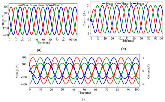
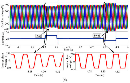
Figure 7.
Grid performance: (a) grid voltage, (b) grid current, and (c) zero phase shift between grid voltage and current means unity power factor and (d) grid side voltage, power, and inverter phase voltage response under some vibration.
4.4. Controller Performance
The performance of the proposed controller was observed in terms of stability of the closed-loop system, sudden load-change response of inverter voltage and current, and fault analysis of the grid current.
4.4.1. Stability
Figure 4 depicts the frequency characteristics of a closed-loop system for using the PIR + HC + LC controller. This curve is also used for determining the stability of the system. It shows the frequency response of the proposed PIR + HC + LC controller in terms of magnitude and phase. The proposed controller demonstrates 150 db damping in the magnitude and the phase changes between 0 and 450 V. It satisfies the condition of stability in negative imaginary theory. It depicts that the fundamental frequency of the proposed controller is very high, and it imposes harmonic frequency in other resonant points; thus, the harmonics of the grid current can be mitigated. The stability of the system is directly dependent on the nature of harmonics.
4.4.2. Sudden Load-Change Response of Inverter
The controller performance is shown in detailed description in this section. It describes the performance of the inverter under the sudden load change effect of voltage and current after the change in the load. Figure 8a shows the load change effect in voltage and Figure 8b shows the load change effect in current. An extra load is applied in time from 0.3 to 0.6 s. In this period, the output current increased for the load changing effect, but it also shows a sinusoidal nature in the time of the load changing period. However, there is no effect of load change in output voltage. It is always in the same nature and sinusoidal form. After removing the extra load from the system, the output current tracks the previous condition within a very short period of time, which can be seen from Figure 8b. The power consumption of the system under the load condition will be low because of the sinusoidal nature of the output current and the constant peak of output voltage during the load change condition.
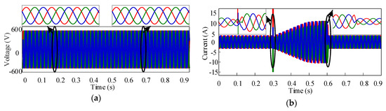
Figure 8.
Load change effect: (a) voltage and (b) current.
4.4.3. Fault Analysis in Grid Current
The grid current is observed under various fault effect conditions in this section. Figure 9 describes the nature of the grid current under different fault conditions. In Figure 9a–c, the fault is applied in phases ‘a’, ‘b’, and ‘c’, respectively. The amplitude of the current is increased during the fault condition. Its peak is in 0 to 20 A in these periods. The fault is applied in between phases ‘a’ and ‘b’; phases ‘b and ‘c’; phases ‘a’ and ‘c’; and phases ‘a’, ‘b’, and ‘c’ in Figure 9d–g, respectively. The amplitude of the current is 0 to 30 A in these periods. Here, the fault is applied in 20 to 40 ms. During the fault condition, the peak of the current increased. After removing the fault, the current recovered its previous balanced condition very quickly, which demonstrates the fast, robust, and dynamic characteristics of the proposed controller.
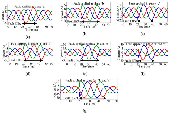
Figure 9.
Fault analysis in the grid current: (a) fault is applied in phase ‘a’; (b) fault is applied in phase ‘b’; (c) fault is applied in phase ‘c’; (d) fault is applied in phases ‘a’ and ‘b’; (e) fault is applied in phases ‘b’ and ‘c’; (f) fault is applied in phases ‘a’ and ‘c’; and (g) fault is applied in phases ‘a’, ‘b’, and ‘c’.
4.5. Comparative Result Analysis
In this section, a comparison of the performances of the different controllers is given in terms of steady-state error or reference tracking capability, load-handling capability, and THD analysis of the proposed controller in comparison with the other controllers. All the results are observed in the MATLAB/Simulink environment. This evaluates the robustness of the proposed controller.
4.5.1. Reference Tracking Capability
The reference tracking capability of the closed-loop system with the PI, proportional integral derivative (PID), PR, PIR, Resonance + LC, and the proposed PIR + HC + LC controllers is investigated and shown in Figure 10a–f, respectively. The PIR + HC + LC controller tracks the reference more effectively than other controllers. In Figure 10a, the reference tracking capability of the PI controller is shown. It shows harmonic distortion, phase shift, and inability to track the reference signal. The performance of the PID controller is also observed, in Figure 10b. The output of the PID controller tracks the reference but with some distortion. It will affect the system response in other conditions. The simulation result of the PR controller is depicted in Figure 10c. It shows slightly lower harmonics and distortion in the current, but in some portions, it exceeds the reference level or is unable to crack the reference signal. Lower harmonics and oscillation are also shown in the output current by using the PIR controller but it exceeds the reference level and distortion occurs. The resonance + LC controller displays less harmonics in the grid current. It tracks the reference more effectively than the PI, PID, PR, and PIR controllers. Excellent reference tracking ability is observed with the proposed PIR + HC + LC controller. The output waveform contains the lowest oscillation and zero phase shift. It tracks the reference without any distortion.
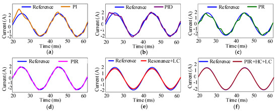
Figure 10.
Reference tracking capability of the controllers. (a) Proportional-integral (PI) controller, (b) proportional integral derivative (PID) controller, (c) proportional resonance (PR) controller, (d) proportional-integral resonance (PIR) controller, (e) Resonance + LC controller, and (f) proposed PIR + HC + LC controller.
4.5.2. Sudden Load-Change Response of Inverter for Different Controllers
Figure 11 displays the sudden load-change effect of the closed-loop system with different controllers. Here, an extra load is added in the system to evaluate the inverter response under the load condition and it is not in the grid-tied mode. The grid was separated from the system during this observation. The load was applied from 0.3 to 0.6 s. In this period, the current increased when using all controllers. The current performance is shown in Figure 11a–f for the PI, PID, PR, PIR, Resonance + LC, and PIR + HC + LC controllers, respectively. After removing the load, all controllers’ output tracks the previous condition of the output current within a very short period, but the time required for each controller is not the same. Some controllers show a fast response and others show a slow response for tracking the previous condition. These phenomena directly affect the power quality of the system by consumption of power during the load change period. All the controllers demonstrated the sinusoidal output current before and after the load change condition. In the current under the load condition, there is a significant oscillation in the output performance when using the PI controller (Figure 11a). The output current is in constant amplitude under the load change period when using the PID controller, as shown in Figure 11b. The output of the PR controller also shows distortion and constant amplitude under the loaded condition. There is less oscillation in the current waveform under the load condition, which is depicted in Figure 11d. By using the Resonance + LC controller, the output in the loaded condition shows less oscillation but the amount of current is high under the condition compared with the previous condition. Thus, the power consumption will be very high when using this controller. Less oscillation occurs with the proposed PIR + HC + LC controller. The output is almost sinusoidal for the proposed controller under the load change condition and the amplitude of the current increased gradually, handling the power consumption effect. It also tracks the previous condition faster than the other controllers.
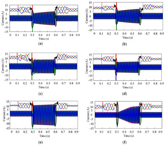
Figure 11.
Sudden load-change effect on the grid current for the (a) PI controller, (b) PID controller, (c) PR controller, (d) PIR controller, (e) Resonance + LC controller, and (f) PIR + HC + LC controller.
4.5.3. THD Analysis
A comparative THD analysis of this system by using different controller is investigated in Figure 12. It describes the total harmonic distortion in the percentage of the grid current by applying different control techniques. The THD is observed in phase ‘a’ only. The THD performance under the PI, PID, PR, PIR, Resonance + LC and PIR + HC + LC controllers is shown in Figure 12a–f, describing a THD of 23.64%, 17.24%, 13.02%, 6.13%, 1.09%, and 0.55% with the PI, PID, PR, PIR, Resonance + LC, and PIR + HC + LC controllers, respectively. Table 2 also describes the comparative THD performance of the controllers in terms of per-cycle distortion of the output curve in the 1st, 2nd, 3rd, 4th, and 5th cycles. Among all the controllers, the THD of the proposed controller is very low. Lower THD indicates the increased efficiency and improved power quality of the system.
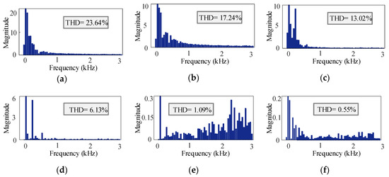
Figure 12.
Total harmonic distortion (THD) analysis with the (a) PI controller, (b) PID controller, (c) PR controller, (d) PIR controller, (e) resonance +LC controller, and (f) PIR + HC + LC controller.
Table 2.
THD analysis of the injected grid current.
4.5.4. Advantages and Limitations of the Controllers
Table 3 depicts the overall performance analysis of the PI, PID, PR, PIR, Resonance + LC, and the proposed PIR + HC + LC controllers. It describes that the implementation and design of the PI controller are very simple. It also has some drawbacks, including reduced stability, inaccuracy, and slow response to the system during disturbance condition. The PID controller has a simple circuitry and minimized both transient and steady-state responses. On the contrary, this control technique cannot work successfully under a high frequency and it also provides a slow response to the system. The PR controller offers reduced steady-state errors and low computational burden to enhance the system performance. The PR controller has some limitations in controlling the harmonics and rapid changes in frequency variation of the system. It also shows inability to handle the load and fault effect. The PIR controller minimizes steady-state errors and controls the changes in frequency variation. It increases the difficulty of the system by creating overshoot and less stability for oscillatory response. The Resonance + LC controller provides phase lead and increases transient response and also introduces implementation complexity. It also shows reference tracking inability in the output current. The proposed PIR + HC + LC control scheme has the advantages of all the control techniques mentioned above and also has the ability to minimize their limitations. It offers less steady-state errors, minimized lower order harmonics, reduced magnitude of error signal, easy to tune, increased transient response, and a successful working ability in frequency variation.
Table 3.
Comparison of the advantages and limitations among the controllers.
5. Conclusions
In this paper, a proportional-integral resonance controller with the feedback of a harmonic compensator and a lead compensator (PIR + HC + LC) was proposed to enhance the power quality and different dynamic responses of an NPC converter-fed grid-tied PV system. The proposed controller not only provides excellent output voltage performance of the PV array but also good inverter performance under sudden load changes and disturbances in the power system. The proposed controller showed sinusoidal output voltage and current with unity power factor. The proposed controller helps to reduce the current THD at about 0.55%, which is much lower than that of the other existing controllers. It also showed a good dynamic response profile against different fault conditions of the grid-tied PV system. Overall, it offered promising results in terms of sudden load change response, reference tracking capability of grid current, THD of injected grid current, and ability to suppress the lower order harmonics. Thus, the proposed controller can be a good aspirant for the other topologies of MLIs in different applications such as grid integration of RESs, microgrids, and industrial motor drive systems. Future work will include improvements to the proposed controller to make the grid-connected renewable energy system more effective with experimental validation.
Author Contributions
Idea and conceptualization, S.J., S.P.B. and M.R.I.; design and simulation, S.J., S.P.B. and S.H.; writing and drawing, S.J., M.K.H., S.H., and M.A.P.M.; revision and correction, S.P.B., M.R.I., and A.Z.K. All authors have read and agreed to the published version of the manuscript.
Funding
This research received no external funding.
Institutional Review Board Statement
Not applicable.
Informed Consent Statement
Not applicable.
Data Availability Statement
Not applicable.
Conflicts of Interest
The authors declare no conflict of interest.
Nomenclature
| NPC | Neutral point clamped |
| THD | Total harmonic distortion |
| LC | Lead compensator |
| HC | Harmonic compensator |
| PLL | Phase-locked loop |
| SPWM | Sinusoidal pulse width modulation |
| MPPT | Maximum power point tracker |
References
- Islam, M.R.; Guo, Y.G.; Zhu, J.G. A high-frequency link multilevel cascaded medium-voltage converter for direct grid integration of renewable energy systems. IEEE Trans. Power Electron. 2013, 29, 4167–4182. [Google Scholar] [CrossRef]
- Mondol, M.H.; Tür, M.R.; Biswas, S.P.; Hosain, M.K.; Shuvo, S.; Hossain, E. Compact Three Phase Multilevel Inverter for Low and Medium Power Photovoltaic Systems. IEEE Access 2020, 8, 60824–60837. [Google Scholar] [CrossRef]
- Islam, M.R.; Guo, Y.G.; Zhu, J.G. A Multilevel Medium-Voltage Inverter for Step-Up-Transformer-Less Grid Connection of Photovoltaic Power Plants. IEEE J. Photovolt. 2014, 4, 881–889. [Google Scholar] [CrossRef]
- Singaravel, M.M.R.; Daniel, S.A. MPPT with single DC–DC converter and inverter for grid-connected hybrid wind-driven PMSG–PV system. IEEE Trans. Ind. Electron. 2015, 62, 4849–4857. [Google Scholar] [CrossRef]
- Rahman, M.A.; Islam, M.R.; Muttaqi, K.M.; Guo, Y.; Zhu, J.; Sutanto, D.; Lei, G. A modified carrier-based advanced modulation technique for improved switching performance of magnetic-linked medium-voltage converters. IEEE Trans. Ind. Appl. 2019, 55, 2088–2098. [Google Scholar] [CrossRef]
- Mondol, M.H.; Uddin, M.S.; Hossain, E.; Biswas, S.P. A Compact and Cost Efficient Multiconverter for Multipurpose Applications. IEEE Access 2020, 8, 86810–86823. [Google Scholar] [CrossRef]
- Haq, S.; Biswas, S.P.; Jahan, S.; Islam, M.R.; Mahmud, M.P.; Kouzani, A.Z. An Advanced Modulation Technique to Improve the Performance of Modular Multilevel Converter. In Proceedings of the 2020 IEEE International Conference on Applied Superconductivity and Electromagnetic Devices (ASEMD), Tianjin, China, 16–18 October 2020; pp. 1–2. [Google Scholar]
- Kumar, N.; Saha, T.K.; Dey, J. Sliding-mode control of PWM dual inverter-based grid-connected PV system: Modeling and Performance Analysis. IEEE J. Emerg. Sel. Top. Power Electron. 2016, 4, 435–444. [Google Scholar] [CrossRef]
- Das, M.K.; Jana, K.C.; Sinha, A. Performance evaluation of an asymmetrical reduced switched multi-level inverter for a grid-connected PV system. IET Renew. Power Gener. 2017, 12, 252–263. [Google Scholar] [CrossRef]
- Shuvra, M.A.; Chowdhury, B. Distributed dynamic grid support using smart PV inverters during unbalanced grid faults. IET Renew. Power Gener. 2019, 13, 598–608. [Google Scholar] [CrossRef]
- Taghvaie, A.; Haque, M.E.; Saha, S.; Mahmud, M.A. A New step-up switched-capacitor voltage balancing converter for NPC multilevel inverter-based solar PV system. IEEE Access 2020, 8, 83940–83952. [Google Scholar] [CrossRef]
- Biswas, S.P.; Anower, M.S.; Sheikh, M.R.I.; Islam, M.R.; Kouzani, A.Z.; Mahmud, M.A.P. A new modulation technique to improve the performance of three phase inverters. In Proceedings of the 2020 IEEE International Conference on Applied Superconductivity and Electromagnetic Devices (ASEMD), Tianjin, China, 16–18 October 2020; pp. 1–2. [Google Scholar]
- Hannan, M.A.; Ghani, Z.A.; Mohamed, A.; Uddin, M.N. Real-Time Testing of a Fuzzy-Logic-Controller-Based Grid-Connected Photovoltaic Inverter System. IEEE Trans. Ind. Appl. 2015, 51, 4775–4784. [Google Scholar] [CrossRef]
- Wang, J.; Mu, X.; Li, Q. Study of Passivity-Based Decoupling Control of T-NPC PV Grid-Connected Inverter. IEEE Trans. Ind. Electron. 2017, 64, 7542–7551. [Google Scholar] [CrossRef]
- Kakosimos, P.; Abu-Rub, H. Predictive control of a grid-tied cascaded full-bridge npc inverter for reducing high-frequency common-mode voltage components. IEEE Trans. Ind. Inform. 2018, 14, 2385–2394. [Google Scholar] [CrossRef]
- Jain, S.; Shadmand, M.B.; Balog, R.S. Decoupled active and reactive power predictive control for PV applications using a grid-tied quasi-Z-source inverter. IEEE J. Emerg. Sel. Top. Power Electron. 2018, 6, 1769–1782. [Google Scholar] [CrossRef]
- Han, Y.; Chen, H.; Li, Z.; Yang, P.; Xu, L.; Guerrero, J.M. Stability analysis for the grid-connected single-phase asymmetrical cascaded multilevel inverter with SRF-PI current control under weak grid conditions. IEEE Trans. Power Electron. 2019, 34, 2052–2069. [Google Scholar] [CrossRef]
- Jafarian, H.; Kim, N.; Parkhideh, B. Decentralized control strategy for AC-stacked PV inverter architecture under grid background harmonics. IEEE J. Emerg. Sel. Top. Power Electron. 2018, 6, 84–93. [Google Scholar] [CrossRef]
- Liu, Q.; Caldognetto, T.; Buso, S. Review and comparison of grid-tied inverter controllers in microgrids. IEEE Trans. Power Electron. 2020, 35, 7624–7639. [Google Scholar] [CrossRef]
- Leon, J.I.; Vazquez, S.; Franquelo, L.G. Multilevel converters: Control and modulation techniques for their operation and industrial applications. Proc. IEEE 2017, 105, 2066–2081. [Google Scholar] [CrossRef]
- Jahan, S.; Biswas, S.P.; Haq, S.; Islam, M.R.; Mahmud, M.A.P.; Kouzani, A.Z. A grid feeding voltage source inverter with an advanced control scheme for solar pv system. In Proceedings of the 2020 IEEE International Conference on Applied Superconductivity and Electromagnetic Devices (ASEMD), Tianjin, China, 16–18 October 2020; pp. 1–2. [Google Scholar]
- Liu, B.; Su, M.; Yang, J.; Song, D.; He, D.; Song, S. Combined Reactive Power Injection Modulation and Grid Current Distortion Improvement Approach for H6 Transformer-Less Photovoltaic Inverter. IEEE Trans. Energy Convers. 2017, 32, 1456–1467. [Google Scholar] [CrossRef]
- Li, Y.W.; He, J. Distribution system harmonic compensation methods: An overview of DG-interfacing inverters. IEEE Ind. Electron. Mag. 2014, 8, 18–31. [Google Scholar] [CrossRef]
- Bighash, E.Z.; Sadeghzadeh, S.M.; Ebrahimzadeh, E.; Blaabjerg, F. Adaptive-harmonic compensation in residential distribution grid by roof-top PV systems. IEEE J. Emerg. Sel. Top. Power Electron. 2018, 6, 2098–2108. [Google Scholar] [CrossRef]
- Mora, A.; Cárdenas-Dobson, R.; Aguilera, R.P.; Angulo, A.; Donoso, F.; Rodriguez, J. computationally efficient cascaded optimal switching sequence MPC for grid-connected three-level NPC converters. IEEE Trans. Power Electron. 2019, 34, 12464–12475. [Google Scholar] [CrossRef]
- Malakondareddy, B.; Kumar, S.S.; Gounden, N.A.; Anand, I. An adaptive PI control scheme to balance the neutral-point voltage in a solar PV fed grid-connected neutral point clamped inverter. Int. J. Electr. Power Energy Syst. 2019, 110, 318–331. [Google Scholar] [CrossRef]
- Alhosaini, W.; Wu, Y.; Zhao, Y. An enhanced model predictive control using virtual space vectors for grid-connected three-level neutral-point clamped inverters. IEEE Trans. Energy Convers. 2019, 34, 1963–1972. [Google Scholar] [CrossRef]
- Rahman, M.M.; Biswas, S.P.; Hosain, M.K.; Sheikh, M.R.I. A second order high performance resonant controller for single phase islanded microgrid. In Proceedings of the 2019 4th International Conference on Electrical Information and Communication Technology (EICT), Khulna, Bangladesh, 20–22 December 2019; pp. 1–6. [Google Scholar]
- Seifi, K.; Moallem, M. An adaptive PR controller for synchronizing grid-connected inverters. IEEE Trans. Ind. Electron. 2019, 66, 2034–2043. [Google Scholar] [CrossRef]
- Shuvo, S.; Hossain, E.; Khan, Z.R. Fixed point implementation of grid tied inverter in digital signal processing controller. IEEE Access 2020, 8, 89215–89227. [Google Scholar] [CrossRef]
Publisher ’s Note: MDPI stays neutral with regard to jurisdictional claims in published maps and institutional affiliations. |
© 2021 by the authors. Licensee MDPI, Basel, Switzerland. This article is an open access article distributed under the terms and conditions of the Creative Commons Attribution (CC BY) license (http://creativecommons.org/licenses/by/4.0/).