Abstract
Smoke extraction systems, either static with natural ventilation, or dynamic with mechanical ventilation are required to keep smoke layer at high levels in many tall atria. It is observed that a design fire with high heat release rate (HRR) is commonly used for designing natural vents, but a low HRR is used for mechanical ventilation system. This will not produce a sustainable environment. There are no internationally agreed on design guides to determine the HRR in the design fire for different extraction systems and scenarios. This issue will be studied using a Computational Fluid Dynamics (CFD)-based software, the Fire Dynamics Simulator (FDS) version 6.7.1. Simulations on natural smoke filling, static and dynamic smoke extractions were carried out in a big example atrium. CFD-FDS predictions were compared with previous full-scale burning tests. Results confirmed that static smoke extraction is a good option for big fires, and a dynamic system is best for small fires. A sustainable new hybrid design combining the advantages of static and dynamic systems is proposed, which could result in a lower smoke temperature and higher smoke layer interface height, indicating a better extraction design.
1. Introduction
There are many construction projects with big atria while developing sustainable urban areas in the Asia-Oceania regions since 1980s [1,2,3,4,5,6,7]. The Greater Bay Area, which includes nine cities in Guangdong, Hong Kong and Macao, is a very good example [8]. Many of buildings with large atria [1,2,3,4,5,6,7,9] have been constructed or planned [8]. It is required that fire safety provisions have to be installed for crowded atria. The smoke layer in a fire has to be kept high to allow people to see through so that smoke will not give adverse effects to people staying inside, occupants trapped inside can locate the exits, firemen can identify the fire sources, and high thermal radiation will not act on the firemen fighting against the fire [10,11,12,13,14]. A high smoke layer will also provide an environment free of toxic smoke for the occupants and reduce thermal radiative heat flux from the hot smoke. There are no design guides with applicable correlation expressions. Performance-based design (PBD) or Fire Engineering Approach (FEA) was thus applied to design smoke extraction systems in big atria to achieve a high smoke layer [15,16,17,18,19].
It is not feasible to study the fire aspects and performance of system design with full-size physical models for most projects. In a fire, there are many conditions which are difficult to be ‘repeated’ or ‘reproduced’ [20]. Prohibitive human and financial resources are required to do the tests. Only a few selected real fire tests are required in some areas to confirm that the smoke layer can be kept at a high level for a small fire. Computational Fluid Dynamics (CFD) fire models have therefore been used for designing the atrium smoke exhaust systems in PBD/FEA projects in recent decades [21,22,23,24,25,26,27]. However, there are numerous problems in using CFD [28,29]. For example, two-dimensional simulations were conducted with only 100,000 cells in the 1990s due to the limited computer capability at that time, and only averaged flow parameters can be predicted using Reynolds-Averaged Navier–Stokes (RANS) equations. The CFD software Fire Dynamics Simulator (FDS) version 6.7.1 [30], developed by the National Institute of Standards and Technology in the USA, became a common design tool 15 years ago. The newer version of FDS is based on the Large Eddy Simulation (LES) and is able to handle up to 5 million computing domains and can be readily executed now even on a personal computer. The simulation results can be applied to predict the parameters of fire hazards, such as estimating the Available Safe Egress Time (ASET) [18,31,32] based on CFD predictions.
Most of the CFD fire models are not properly validated due to high cost and other difficulties in conducting large-scale fire tests. PBD-FEA projects using the CFD models are always challenged by different parties [19,22]. Consequently, hot smoke tests are required to demonstrate the system performance in the atrium with a small fire up to two MW. In Hong Kong, hot smoke tests are required to evaluate the performance of smoke extraction systems in halls of irregular shape or halls taller than 12 m [13,33].
There are two types of smoke extraction systems in large halls: natural venting or static smoke extraction systems, and mechanical ventilation systems or dynamic smoke extraction [11,12,33,34]. HRR is important in designing a smoke extraction system [35]. It is observed that large design fires up to 20 MW are commonly used for designing natural vents, while a small design fire (e.g., five MW) is commonly used for mechanical ventilation [13,19,36]. It is obvious that fire size should not be a function of the venting method that depends on how the combustibles are burnt. Fire size should be selected based on hazard assessment. The performance of the two smoke extraction systems under fires of different HRR will be further explored in this paper using CFD simulation. As an important purpose of the paper, a new proposed sustainable hybrid design combining static and dynamic extraction system will be explored and compared with the traditional ones, which could result in a lower smoke temperature and higher smoke layer interface height, indicating a better extraction design.
For example, a big atrium with 150 m length, 40 m width and 30 m height as shown in Figure 1 was used to study the performance of the two traditional extraction systems under big, medium and small fires as well as the proposed hybrid extraction system in the same conditions. The CFD-FDS predictions on smoke extraction were validated using full-scale burning tests data in two example buildings with atria [22,29,37,38]. This included smoke filling and extraction data in the PolyU/USTC Atrium in Mainland China [39,40] and hot smoke test data in an irregular atrium in Hong Kong [41,42].
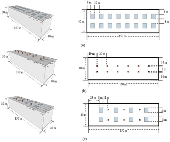
Figure 1.
Smoke extraction designs in the example atrium. (a) Natural vents; (b) Mechanical ventilation; (c) Proposed hybrid system.
2. Atrium Smoke Movement
The smoke filling the atrium, the natural ventilation in case of fire, the mechanical ventilation in case of fire, the sprinklers in atria and their effectiveness, the spill plume dynamics and others were studied by physical experiments and numerical simulations worldwide.
As a beginning of the foreign literature review on the topic, the first full-scale testing of smoke behavior in large scale spaces was reported in Japan in 1985. This was a full-scale experiment in a seven-story atrium with dimensions of 30 m × 24 m × 26.4 m with methanol as a fuel and with an HRR of 1.3 MW. In this research, Yamata et al. studied the smoke filling process and ventilation methods [43]. Earlier in the same year, they examined the same occurrences theoretically [44]. The comparison demonstrated a good match with the real experiment. That same year in Sweden, Hagglund et al. made a full-scale test in the Cubic Hall with the dimensions of 5.62 m × 5.62 m × 6.15 m and with sources with an HRR from 70 to 630 kW [45]. In the 1990s, smoke filling experiments became popular in Australia [46] as well as big full-scale experiment in a stadium, reported by Dillon [47].
Later in 1997, fire experiments in the field of the mechanical ventilation of smoke in the case of a fire were carried out in Canada by Lougheed and Hadjisophocleous in a compartment with the dimensions of 9 m × 6 m × 5.5 m with a square propane sand burner an an HRR from 15 kW to 1 MW [48]. Later experiments by Lougheed et al. were carried out in a facility with dimensions of 13.11 m × 17.22 m × 12.2 m, which is approximately two times bigger than the previous one with possibilities of fires with HRRs from 250 kW to 5 MW [49].
The beginning of the current millennium can be regarded as a cornerstone in the burning experiments in atria. There are currently two bigger globally known facilities where full-scale burning experiments in atria can be conducted.
The first model atrium is located in at the campus of the University of Science and Technology of China at Hefei. It is a big concrete construction jointly built by The Hong Kong Polytechnic University and the University of Science and Technology of China with internal dimensions of 22.4 m × 11.9 m × 27 m. In 2000, experimental studies on natural smoke filling in this atrium with liquid pool fires up to 1.6 MW were conducted [39].
The second model atrium is in the Technological Metal Centre in Murcia, Spain. Researchers from the University of Jaén, The University of Comillas, with the collaboration of the Imperial College of London, MAPFRE and the fire consultancy firm JVVA Fire and Risk have undertaken several full-scale fire tests in the facility. The dimensions of the Murcia Fire Atrium are 19.5 m × 19.5 m × 17.5 m and a pyramidal roof raised 2.5 m at the center. It is made of aluminum construction with several vents in the walls and four exhaust fans at the roof [50].
As a beginning of this project, Gutierrez-Montes et al. made an overview of smoke and fire dynamics in atria and enclosures including: atrium typology and definitions; atrium fire dynamics and safety problems; fire strategies and atrium design; computer modeling of atria; sprinklers and smoke detectors in atria; the process of smoke filling in atria; natural venting of smoke in atria; mechanical venting of smoke in atria; spill plume dynamics in atria; and design trends in fire safety in atria [51]. The first reports from the practical research in Murcia Fire Atrium are from 2008 with a numerical model and validation experiments of atrium enclosure fire [50]. Later, several articles were reported, including low and medium full-scale atrium fire tests and numerical validations of FDS followed by an experimental and numerical study of the smoke ventilation in atrium fires under dynamic ventilation performance where the validation of two fire experiments of 2.3 MW and 5.3 MW was made [52,53,54,55]. The latest full-scale fire experiments and simulations in Murcia under transient and asymmetric venting conditions were reported in 2016 with sources with different HRRs (1.7 MW, 2.3 MW, 3.9 MW, 5.3 MW) with a good agreement between the fire tests and the numerical set-up [56]. The latest computational research was reported by Zidek et al. in 2019 where fire tests in the Murcia Fire Atrium were used to validate FDS results. Three FDS cases were presented with the same HRR of 2.34 MW but different dimensions of the computational domain (mesh cell sizes). The results showed a good match with the real fire experiment in the atrium, except the plume region near the fire pool [57].
The current research aims not only to add some additional value to the atrium extraction system knowledge by comparing and validating traditional full-scale burning test with the FDS computational capacities but also to present a hybrid extraction system for atriums combining the advantages of traditional methods.
3. Smoke Extraction in the Example Atrium
The calculations for static and dynamic smoke extraction systems are presented in Appendix A and can be summarized as follows.
Following the Hong Kong guides [33], the minimum number of natural vents Ns in this example atrium, without having plugholing, is 12. Smoke must reach the nearest exhaust system without travelling more than 30 m [33]. A minimum of one smoke outlet must be provided in every 500 m2 floor area. In order to satisfy both the distance to the smoke exhaust and the area served by one smoke outlet, a total of 16 natural vents were used. The area served by each smoke exhaust outlet was 50 m2. The positions of the vents are shown in Figure 1a.
For a dynamic smoke extraction system, the minimum number of mechanical vents ND is also 12. The minimum volume flow rate for each mechanical vent is 33.33 m3/s. According to the code [33], the minimum mechanical ventilation area SMV is 4.17 m2. Therefore, 12 mechanical vents were used in this example atrium to extract smoke. The mechanical ventilation vents are shown in Figure 1b.
A thick enough smoke layer has to be formed below the ceiling to have adequate buoyancy before opening the vents. The activation time can be determined by referring to the smoke layer interface height [29]. When the smoke layer interface height reaches about 30% to 50% of the ceiling height, the smoke extraction system should be activated [58]. The activation time of the system is determined from the HRR of the fire and other factors such as the sensitivity of the detector or activating mechanism and the threshold setting agreed on by the authorities.
The stability of the plume generated by a fire is affected by the make-up air inlets, even for a small make-up air inlet. This would affect the performance of natural venting systems. According to the suggestion by NFPA-92 [34], the average velocity of make-up air is 1 m/s in order to maintain satisfactory functioning of the whole system.
In general, the minimum supply or supplemental air rate must be 80% of the exhaust rate [33]. In using mechanical methods to supply air, the air must be extracted from the outside by a separate system or a general air conditioning system [33]. Therefore, the volume of supply air per unit time VSA is 320 m3/s.
4. Numerical Simulation of Smoke Extraction in the Example Atrium
A steady fire with fixed size [18] has been used in designing smoke control systems in PBD-FEA projects for 30 years. The HRR is limited to a maximum value even for unsteady fire [34]. Smoke extraction systems can then be designed quickly but effectively by using a constant fire size. A 4 m by 4 m square pool fire was put at the center of the example atrium floor. Four groups of simulations, each with three cases of fire sizes commonly accepted in different applications (5 MW, 20 MW and 50 MW), for a specified scenario were considered in the example atrium with the model schematically shown in Figure 2.
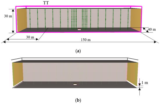
Figure 2.
The example atrium. (a) Computational domain of the example atrium; (b) With make-up air inlets at the bottom.
The computational domain of the example atrium using FDS after preliminary grid size sensitivity study is shown in Figure 2a. The objective of the study is to compare the performance of different smoke exhaust systems. In this example design, two air inlets of 1 m height at the atrium floor were provided with the schematic diagram shown in Figure 2b.
The details of the four groups of simulations shown in Table 1 are:

Table 1.
Summary of numerical simulation groups.
- Group 1: Natural smoke filling without any ventilation
- Group 2: Static smoke extraction with natural vents
- Group 3: Dynamic smoke extraction with mechanical ventilation
- Group 4: Hybrid smoke extraction
The simulation of the mechanical exhaust vent was made by setting a series of VENTs and designating a SURF_ID with specified volume flow rates in the FDS input file. This fan modeling method has also been adopted in much of the previous research. From the perspective of scientific issues, the change rule of the mechanical smoke extraction with the actual air volume at the smoke vent was studied. The simulation of the natural vent was performed by setting a series of OPENs in the FDS input file with a certain area, which meant pressure outlets from inside of the atrium to the atmosphere through the opening area.
The initial temperature of both inside and outside of the example atrium was 20 °C, and the initial pressure of both inside and outside was 101,325 Pa. No wind was set in the simulation.
The two main parameters used to validate the simulation results are the transient vertical temperature distributions and the descending time of the smoke layer. The smoke layer interface height is an indication of the performance of smoke extraction system and determined as described later. If the smoke layer interface height can be kept at a certain value, occupants are able to escape safely.
The values of the two main parameters can be directly obtained by CFD-FDS simulation. The smoke interface height at Position TT outside the plume for convenient determination of smoke layer interface and the temperature under the atrium ceiling at Position TT are selected as the typical value for analysis, which is 30 m away from the left side and about 40 m away from the fire source edge, as shown in Figure 2a.
Smoke layer interface height is obtained by simulation using a steady fire with a constant HRR. In order to get a certain smoke layer thickness without plugholing during smoke extraction, the activation times of vents are 150 s, 50 s and 30 s for 5 MW, 20 MW and 50 MW fires, respectively. The simulation time of each case is 500 s.
Group 1 simulations on natural smoke filling are taken as the reference. Smoke almost filled up the whole space after 300 s. The smoke layer interface height of the three fire sizes is shown in Figure 3a and the smoke temperature rise is presented in Figure 3b.
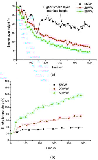
Figure 3.
Natural smoke filling in the example atrium. (a) Smoke layer interface height at TT; (b) Smoke temperature at TT.
The N-percentage Rule [59,60] was applied to the vertical temperature profile obtained at different appropriate locations. The vertical temperature profile contains temperatures at heights y1, y2, …, ym with y1 at the lowest level, and ym at the top. The temperatures predicted at time t are T (y1, t), T (y2, t), …, T (ym, t). A reference upper layer temperature ΔTRef (t) at t is determined within the burning duration tb.
is the maximum value of in the interval from 0 to t and is the initial temperature at with values very close to the ambient value T0.
The smoke layer interface y is determined by the N-percentage rule to be the value of height y1, …, ym satisfying the following:
N was commonly taken to be 10, 15 and 20 [41,58]. In this study, the value of N was taken to be 20 from 100 s to 400 s and 25 for 500 s. The predicted vertical temperature profile was used to determine the hot air layer height. Air temperatures at every 1 m interval height at the x = 30 m in the atrium are shown in Figure 4a–e.
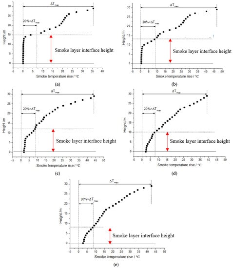
Figure 4.
Vertical temperature profiles and N-percentage rule. (a) 100 s; (b) 200 s; (c) 300 s; (d) 400 s; (e) 500 s.
The performance of natural vents with and without make-up air is shown in Figure 5a–c. It is observed that a stable smoke layer was not formed with natural smoke vent under small fire without make-up air.
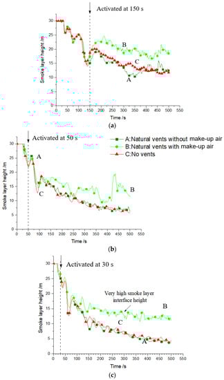
Figure 5.
Smoke layer interface height at TT with and without make-up air. (a) Small 5 MW fire; (b) Medium 20 MW; (c) Big 50 MW fire.
Natural vent was not able to take smoke away from the atrium under medium and big fires when there was no make-up air. Air circulation was blocked. Without fresh air makeup from outside, the whole atrium cannot remain at a positive pressure relative to outside, so that smoke could not move out. Therefore, supplying adequate air below the smoke layer is very important to extract smoke. Otherwise, natural venting systems would not work effectively.
5. Simulation Results for the Example Atrium
The performance of the two types of smoke exhaust systems is evaluated by simulating the smoke environment inside the example hall. The performance of a ventilation system is determined by the stable smoke layer interface height. Simulation result based on a series of temperature thermocouples at a vertical plane labeled TT, which are 30 m away from the left side and about 40 m away from the fire source edge, as shown in Figure 2a.
5.1. Group 1 Simulation with Natural Smoke Filling
- Case 1a with 5 MW Fire
The smoke layer interface height dropped to about 10 m above the floor at around 460 s, and the whole space was filled up by smoke and the temperature increased to 50 °C under the situation of no openings.
- Case 1b with 20 MW fire
The smoke layer interface height dropped to about 5 m above the floor, and the whole space was filled up by smoke and the temperature increased to 80 °C under the situation of no openings.
- Case 1c with 50 MW fire
The smoke layer interface height dropped to about 2 m above the floor and the whole space was filled up by smoke and the temperature increased to 140 °C under the situation of no openings.
5.2. Group 2 with Static Smoke Extraction
- Case 2a with 5 MW Fire
The performance of natural vents was not satisfactory. The smoke layer interface height remained steady at 13 m at 460 s.
- Case 2b with 20 MW fire
The smoke layer interface height remained steady at about 12 m high. The natural venting system showed better performance than mechanical vents.
- Case 2c with 50 MW fire
The smoke layer interface height remained steady at about 12 m high. The natural venting system showed best capability of smoke control in the big fire than the other two smoke exhaust systems.
5.3. Group 3 with Dynamic Smoke Extraction
- Case 3a with 5 MW Fire
The smoke layer interface height remained at the 13 m level after 500 s by mechanical vents.
- Case 3b with 20 MW fire
The smoke layer interface height remained at 11 m high by mechanical venting system.
- Case 3c with 50 MW fire
The smoke layer interface height remained at 8 m high by mechanical venting system.
The curves of the smoke layer interface height by the two smoke exhaust systems compared with smoke natural filling are shown in Figure 6a–c for smoke layer interface height at Position TT. As these four curves show, the smoke exhaust capacity of mechanical smoke exhaust is best when the fire is relatively small. This is because the buoyancy of the smoke generated by the small fire is not strong enough, which would lead to an insufficient pressure difference for the natural smoke exhaust to work well.
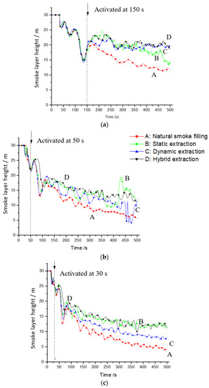
Figure 6.
Smoke layer interface height at TT. (a) Small 5 MW fire; (b) Medium 20 MW fire; (c) Big 50 MW fire.
In medium fire, the performance of the three types of smoke exhaust systems is similar. Natural smoke exhaust is not good for small fires, and mechanical smoke exhaust is not good for big fires.
In the big fire cases, as seen by the results, the static and hybrid extraction systems have similar performance and are much better than the dynamic system. The results again show that the natural smoke exhaust systems are better for big fires.
6. New Hybrid Design for Sustainable Smoke Extraction
It is clear from the above results that a static smoke extraction system with natural vent is not able to take out smoke from small fires. Similarly, a dynamic smoke extraction system with mechanical ventilation is not good for big fires. A hybrid design that combines the two is proposed to produce a sustainable and safe atrium. Half of the volume of smoke is extracted by natural vents, and the other the other half is extracted by mechanical vents.
The calculations for the proposed hybrid system are presented in Appendix B and can be summarized as follows.
For natural vents, a smoke extraction rate VNV1 of 200 m3/s. The area of the vent SNV1 is 400 m2. The number of natural vents N1 in the new design is six. In order to satisfy both the distance to smoke exhaust and the area served by one smoke outlet, eight natural vents were used to extract smoke by static system. The area of each natural vent inlet is 50 m2.
For dynamic smoke extraction, the volume flow rate VMV1 for the new design is 200 m3/s. The number of mechanical vents NMV1 is six. The mechanical vent area for each vent SMV1 is 25 m2. The volume flow rate for each mechanical vent SMV1 is 4.17 m3/s.
Eight vents for the natural venting system and another six vents for the mechanical venting system are used with the schematic shown in Figure 1c.
The last group (Group 4) of simulations was carried out for this hybrid design under the fire sizes of 5 MW, 20 MW and 50 MW. The transient smoke layer interface heights are also plotted in Figure 6 together with the Group 2 and 3 predictions.
- Case 4a with 5 MW fire
The performance of the hybrid system is similar to the other two systems with the smoke layer interface heights lying between those two curves.
- Case 4b with 20 MW fire
The performance of the hybrid system is efficient to keep smoke layer at high level.
- Case 4c with 50 MW fire
The performance of the hybrid system can also keep smoke layer at high level.
The static smoke extraction system performs the best for a large fire. The driving force due to buoyancy is strong enough to give a sufficient pressure differential between the vents.
7. Validation of CFD-FDS Simulation Results
Smoke filling and extraction simulations by CFD-FDS [29,37] were validated by two cases.
7.1. PolyU/USTC Atrium
Experimental studies on natural smoke filling in the PolyU/USTC Atrium with liquid pool fires with HRR up to 1.6 MW were conducted in 2000 [39].
The geometry of the PolyU/USTC Atrium is shown in Figure 7a with details explained elsewhere [39,40]. The internal dimensions of the PolyU/USTC Atrium are 22.4 m long, 11.9 m wide and 27 m tall.
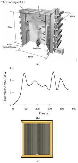
Figure 7.
The PolyU/USTC Atrium [39]. (a) Schematic; (b) HRR of pool fires [2]; (c) Schematic of FDS input.
The experimental conditions were as follows: closed ceiling vents and side windows of the atrium with a gap of 20 cm high at the bottom of the wall. The HRR was an input parameter from the experimental results. The curve of HRR is shown in Figure 7b. From the curve, the pool fires were similar to an unsteady t2-fire at the beginning and then became a steady fire. Two grid systems were used: coarse at 0.4 m × 0.4 m × 0.4 m and fine at 0.2 m × 0.2 m × 0.2 m. The modeling schematic is shown in Figure 7c with a grid system of 0.4 m × 0.4 m × 0.4 m.
A lot of data obtained using CFD-FDS is shown in the following charts. The maximum smoke temperature rise ΔTmax was up to 45 °C, which is over twice that in the experimental results (see Figure 8). Values of smoke layer interface height by simulation are close to experimental results, which are clearly shown in the curves in Figure 9. In order to save computer time, the simulation duration of ‘fine grid’ is made shorter.
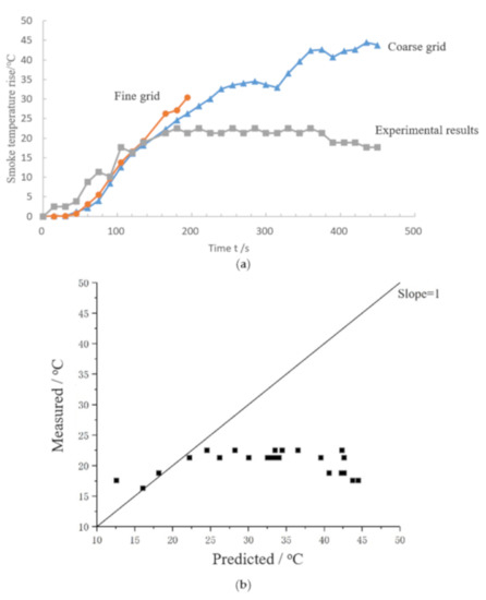
Figure 8.
Results for maximum smoke temperature rise for PolyU/USTC Atrium. (a) Transient smoke temperature rise; (b) Predicted smoke temperatures rise for coarse grid.
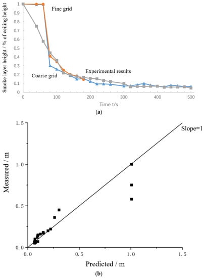
Figure 9.
Smoke layer interface heights for PolyU/USTC Atrium. (a) Transient smoke layer interface height; (b) Predicted smoke layer interface heights for coarse grid.
As the simulation results of the PolyU/USTC atrium show, the predicted smoke temperature rise is a little bit higher than the experimental results, but the smoke layer interface height agrees very well with the measured data. By comparison with experimental results, the results of coarse grid are good enough for prediction.
7.2. Irregular Atrium in Hong Kong
Another validation case is an atrium in Hong Kong reported earlier in 2007 [40,57].
An irregular atrium geometry shown in Figure 10a is considered. Its floor area is 35 m by 9 m, with a ceiling height of 28 m. The atrium is equipped with a mechanical smoke exhaust system with a designed volumetric flow rate of 47.8 m3/s. Hot smoke tests were carried out [41,58].
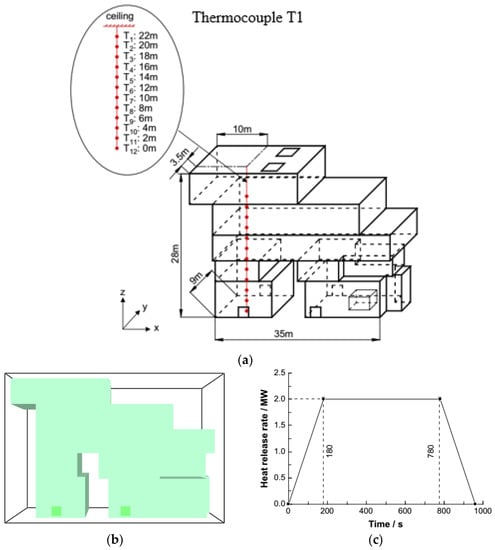
Figure 10.
Irregular atrium in Hong Kong [58]. (a) Geometry; (b) Input schematic drawing; (c) Input HRR.
The schematic of CFD-FDS input and HRR are shown in Figure 10c. Figure 10b shows the grid size 0.5 m × 0.5 m × 0.5 m. The smoke temperature was recorded at 12 positions as in the experiment. From the vertical temperature profile, the smoke layer interface height was determined. The predicted and measured results are plotted in Figure 11a,b.
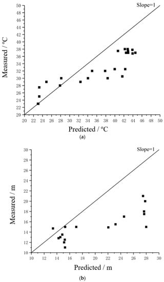
Figure 11.
Predicted results for the irregular atrium in Hong Kong. (a) Predicted temperatures at T1; (b) Predicted smoke layer interface heights.
As shown in the plots of smoke temperature and smoke layer interface height, most points are near to the line with slope = 1, meaning that the simulation results agree well with the experimental results.
It is observed that CFD-FDS can give fairly reasonable predictions in the two atria when compared with the experimental data. The input parameters and geometry are very important to obtain accurate results using CFD-FDS.
8. Discussion
Buoyancy is demonstrated by the above CFD-FDS predictions to be important in removing smoke by static smoke extraction systems. The static extraction system is thus more appropriate for a fire with a large HRR. A large fire can produce enough buoyancy to form a thick enough hot smoke layer. For a small fire with low HRR at the initial stage, a dynamic smoke extraction system performs better. The fan exhaust rate is a key part in designing a dynamic smoke extraction system.
For natural smoke filling without any smoke exhaust systems, smoke spreads in the whole space rapidly, producing a threat to the people inside. A static smoke exhaust system can extract smoke for bigger fires with higher HRR due to strong buoyancy. The static smoke extraction system performs well in removing smoke away from the hall with large volume space, as indicated in the third case of Group 3 with a 50 MW fire. The bigger the fire size, the bigger the air entrainment rate to the plume and hence the higher the exhaust rate required for a dynamic smoke extraction system. However, for smaller fires with lower HRR, buoyancy is insufficient to give a stable smoke layer. A static smoke extraction system with natural vents cannot perform well in keeping a stable smoke layer height. Therefore, dynamic smoke extraction with mechanical ventilation is needed to remove smoke, as shown in the CFD-FDS predictions for a 5 MW fire.
For the hybrid system combining the two extraction systems as proposed by numerical simulation, the operation times are important. The volume of smoke extracted by the mechanical fan might not be able to meet the requirement in removing smoke from the entire hall space. However, combining the static smoke vent will be effective. This will not generate solid waste in replacing the active system.
In summary, the proposed hybrid design will produce a sustainable smoke extraction system that uses less electrical power in operating the fan and is capable of keeping the smoke layer high under both small and big fires.
9. Conclusions
The performance of static and dynamic smoke extraction systems in an example atrium were studied using CFD-FDS in this paper. The objective was to compare the efficacy of mechanical ventilation and natural ventilation for small, medium and large fires. The CFD-FDS simulations on natural smoke filling, static and dynamic smoke extractions with three design fires of 5 MW, 20 MW and 50 MW confirmed that static smoke extraction is good for big fires but not good for taking smoke out under the initial stage of small fires. A dynamic smoke extraction system performs well for small fires, but not for big fires. A new hybrid design combining static and dynamic systems is proposed to produce a sustainable and safe atrium and is expected to perform well in both big and small fires.
Author Contributions
Conceptualization, M.L.I., W.P. and Q.W.; methodology, M.L.I., W.P. and Q.W.; software, W.P. and Q.W.; validation, M.L.I. and W.P.; formal analysis, M.L.I., W.P. and Q.W.; investigation, M.L.I. and W.P.; resources, W.K.C.; data curation, M.L.I. and Q.W.; writing—original draft preparation, Q.W.; writing—review and editing, M.L.I., W.P. and W.K.C.; visualization, Q.W.; supervision, W.K.C.; project administration, W.K.C.; funding acquisition, W.K.C. All authors have read and agreed to the published version of the manuscript.
Funding
The work described in this paper was supported by a grant from the Research Grants Council of the Hong Kong Special Administrative Region for the Theme-Based Research Scheme Project “Safety, Reliability, and Disruption Management of High Speed Rail and Metro Systems” (Project No. T32-101/15-R) with account number 3-RBAC.
Institutional Review Board Statement
Not applicable.
Informed Consent Statement
Not applicable.
Data Availability Statement
The data presented in this study is available on request from the authors.
Conflicts of Interest
The authors declare no conflict of interest. The funder had no role in the design of the study; in the collection, analyses, or interpretation of data; in the writing of the manuscript, or in the decision to publish the results.
Appendix A. Calculations for Static and Dynamic Smoke Extraction Systems
A value of 8 air changes per hour is specified in Hong Kong. The smoke extraction rate Vsmoke in the example atrium is given by:
Vsmoke = 150 × 40 × 30 × 8 m3/h = 1,440,000 m3/h = 400 m3/s
For static smoke extraction system with natural vents, taking the average velocity at natural vents on the ceiling to be 0.5 m/s, the minimum venting area SNV is:
The minimum number of natural vents Ns in this example atrium, without plugholing, is:
For dynamic smoke extraction system, the minimum number of mechanical vents ND is as follows:
The minimum volume flow rate for each mechanical vent is:
According to the codes, for efficient extraction, the maximum velocity of mechanical vents on the ceiling is above 8 m/s. Thus, the minimum mechanical ventilation area SMV is:
The volume of supply air per unit time VSA is as follows:
VSA ≥ 1,440,000 × 0.8 m3/h = 1,152,000 m3/h = 320 m3/s
Appendix B. Calculations for the Proposed Hybrid System
For natural vents, the smoke extraction rate VNV1 is given by:
VNV1 = Vsmoke/2 = 400/2 m3/s = 200 m3/s
The area of vent SNV1 is:
The number of natural vents N1 in the new design is:
For dynamic smoke extraction, the volume flow rate VMV1 for the new design is:
VMV1 = Vsmoke/2 = 400/2 m3/s =200 m3/s
The number of mechanical vents NMV1 is as follows:
The mechanical vent area for each vent SMV1 is:
The volume flow rate for each mechanical vent SMV1 is:
References
- Chow, W.K.; Wong, W.K. On the simulation of atrium fire environment in Hong Kong using zone models. J. Fire Sci. 1993, 11, 3–51. [Google Scholar] [CrossRef]
- Chow, W.K. Smoke filling in atria: Time constant. Build. Serv. Eng. Res. Technol. 1994, 15, 165–169. [Google Scholar] [CrossRef]
- Chow, W.K.; Li, J. (SNV4a1) Wind effects on performance of static smoke exhaust systems: Horizontal ceiling vents. ASHRAE Trans. 2004, 110, 479–488. [Google Scholar]
- Chow, W.K.; Li, J. On the bidirectional flow across an atrium ceiling vent. Build. Environ. 2011, 46, 2598–2602. [Google Scholar] [CrossRef]
- Chow, W.; Li, J. Wind action on natural smoke exhaust in atria. J. Comput. Sci. 2018, 28, 140–147. [Google Scholar] [CrossRef]
- Shi, C.L.; Lu, W.Z.; Chow, W.K.; Huo, R. An investigation on spill plume development and natural filling in large full-scale atrium under retail shop fire. Int. J. Heat Mass Transf. 2007, 50, 513–529. [Google Scholar] [CrossRef]
- Chow, W.K.; Lo, H.H.W. Scale Modeling on Natural Smoke Filling in an Atrium. Heat Transf. Eng. 2008, 29, 76–84. [Google Scholar] [CrossRef]
- Chow, W.K.; Chow, C.L. Fire and explosion hazards to watch in developing big dense areas such as the Guangdong-Hong Kong-Macao Greater Bay Area. J. Chang. Univ. Nat. Sci. Ed. 2020, 32, 33–44. [Google Scholar]
- Xing, Z.; Mao, J.; Huang, Y.; Zhou, J.; Mao, W.; Deng, F. Scaled experimental study on maximum smoke temperature along corridors subject to room fires. Sustainability 2015, 7, 11190–11212. [Google Scholar] [CrossRef]
- Hansell, G.O.; Morgan, H.P. Design approaches for smoke control in atrium buildings. In Building Research Establishment Report BR258; Building Research Establishment: Garston, UK, 1994. [Google Scholar]
- Klote, J.H.; Milke, J.A. Principles of Smoke Management; American Society of Heating, Refrigerating and Air-Conditioning Engineers, Society of Fire Protection Engineers: Atlanta, GA, USA, 2002. [Google Scholar]
- Chow, W.K.; Li, J. On atrium smoke management system design. ASHRAE Trans. 2005, 111, 395–406. [Google Scholar]
- Chow, W.K. On carrying out atrium hot smoke tests. Archit. Sci. Rev. 2005, 48, 105–107. [Google Scholar] [CrossRef]
- Choi, M.; Lee, S.; Hwang, S.; Park, M.; Lee, H.-S. Comparison of emergency response abilities and evacuation performance involving vulnerable occupants in building fire situations. Sustainability 2020, 12, 87. [Google Scholar] [CrossRef]
- Society of Fire Protection Engineers. SFPE Engineering Guide to Performance-Based Fire Protection Analysis and Design of Buildings; Society of Fire Protection Engineers: Bethesda, MD, USA, 2001. [Google Scholar]
- Buildings Department. Code of Practice for Fire Safety in Buildings 2011; Buildings Department: Hong Kong, China, 2011. [Google Scholar]
- Chow, W.K.; Dong, X. Legislation, codes of practice and standards in Hong Kong and mainland China. In Fire from First Principles, 4th ed.; Stollard, P., Ed.; Routledge: New York, NY, USA, 2014; Chapter 10. [Google Scholar]
- Chartered Institution of Building Services Engineers. CIBSE Guide E: Fire Engineering; Chartered Institution of Building Services Engineers: London, UK, 2017. [Google Scholar]
- Chow, W.K. Performance-based approach to determining fire safety provisions for buildings in the Asia-Oceania regions. Build. Environ. 2015, 91, 127–137. [Google Scholar] [CrossRef]
- Hirschler, M.M. Repeatability and reproducibility of fire tests for cigarette ignition of upholstered furniture composites. Fire Mater. 1998, 22, 25–37. [Google Scholar] [CrossRef]
- Chow, W.K. On ventilation design for underground car parks. Tunn. Undergr. Space Technol. 1995, 10, 225–246. [Google Scholar] [CrossRef]
- Chow, W.K. Application of computational fluid dynamics in building services engineering. Build. Environ. 1996, 31, 425–436. [Google Scholar] [CrossRef]
- Cox, G. Turbulent closure and the modeling of fire by using computational fluid dynamics. Philos. Trans. R. Soc. A 1998, 356, 2835–2854. [Google Scholar] [CrossRef]
- Novozhilov, V. Computational fluid dynamics modeling of compartment fires. Prog. Energy Combust. Sci. 2001, 27, 611–666. [Google Scholar] [CrossRef]
- Zhang, B.; Zhang, J.; Lu, S.; Li, C. Buoyancy-driven flow through a ceiling aperture in a corridor: A study on smoke propagation and prevention. Build. Simul. 2015, 8, 701–709. [Google Scholar] [CrossRef]
- Gong, J.; Li, Y. CFD modelling of the effect of fire source geometry and location on smoke flow multiplicity. Build. Simul. 2010, 3, 205–214. [Google Scholar] [CrossRef]
- Hasnain, S.A.; Nasif, M.S.; Pao, W.; Al-Waked, R. Numerical investigation of smoke contamination in atrium upper balconies at different down stand depths. Build. Simul. 2017, 10, 365–381. [Google Scholar] [CrossRef]
- Chow, W.K. A discussion on applying computational fluid dynamics in performance-based design for fire safety provisions. Invited speech. In Proceedings of the 10th Asia-Oceania Symposium on Fire Science and Technology, Tsukuba, Japan, 5–7 October 2015. [Google Scholar]
- Chow, W.K.; Yin, R. A new model on simulating smoke transport with computational fluid dynamics. Build. Environ. 2004, 39, 611–620. [Google Scholar] [CrossRef]
- McGrattan, K.B.; McDermott, R.J.; Weinschenk, C.G.; Forney, G.P. Fire Dynamics Simulator Users Guide, 6th ed.; NIST Special Publication 1019, National Institute of Standards and Technology, US Department of Commerce: Washington, DC, USA, 2013. [Google Scholar]
- Chow, W.K. Letter to the Editor: Comment on ‘RSET/ASET, a flawed concept for fire safety assessment’ by Babrauskas, V., Fleming, J.M. and Russell, B.D., Fire and Materials, Vol. 34, pp. 341–355 (2010). Fire Mater. 2013, 37, 257–258. [Google Scholar] [CrossRef]
- Babrauskas, V.; Fleming, J.M.; Russell, B.D. RSET/ASET, a flawed concept for fire safety assessment. Fire Mater. 2010, 34, 341–355. [Google Scholar] [CrossRef]
- Fire Services Department. Codes of Practice for Minimum Fire Service Installations and Equipment and Inspection Testing and Maintenance of Installation and Equipment; Fire Services Department, Hong Kong Special Administration Region: Hong Kong, China, 2012. [Google Scholar]
- National Fire Protection Association. NFPA 92 Standard for Smoke Control Systems; National Fire Protection Association: Quincy, MA, USA, 2012. [Google Scholar]
- Babrauskas, V.; Peacock, R.D. Heat release rate: The single most important variable in fire hazard. Fire Saf. J. 1992, 18, 255–272. [Google Scholar] [CrossRef]
- Chow, C.L.; Li, J. An analytical model on static smoke exhaust in Atria. J. Civ. Eng. Manag. 2010, 16, 372–381. [Google Scholar] [CrossRef]
- Kerber, S.; Milke, J.A. Using FDS to simulate smoke layer interface height in a simple atrium. Fire Technol. 2007, 43, 45–75. [Google Scholar] [CrossRef]
- US Nuclear Regulatory Commission. Verification and Validation of Selected Fire Models for Nuclear Power Plant Applications (NUREG-1824, Vols. 1–7)—Draft Report for Comment; US Nuclear Regulatory Commission, Office of Nuclear Regulatory Research: Washington, DC, USA, 2007. [Google Scholar]
- Chow, W.K.; Fong, N.K.; Cui, E.; Ho, P.L.; Wong, L.T.; Huo, R.; Fan, W.; Li, Y.; Yuan, L. PolyU/USTC Atrium: A full-scale burning facility—Preliminary experiments. J. Appl. Fire Sci. 1999, 8, 229–241. [Google Scholar]
- Chow, W.K.; Li, Y.Z.; Cui, E.; Huo, R. Natural smoke filling in atrium with liquid pool fires up to 1.6 MW. Build. Environ. 2001, 36, 121–127. [Google Scholar] [CrossRef]
- Chow, W.K.; Pang, E.C.L.; Han, S.S.; Dong, H.; Zou, G.W.; Gao, Y.; Huo, Y.; He, Z.; Zou, J.F.; Li, K.; et al. Atrium hot smoke tests in a big shopping complex. J. Appl. Fire Sci. 2005, 14, 137–169. [Google Scholar] [CrossRef]
- Chow, W.K.; Li, S.S.; Gao, Y. Numerical studies on atrium smoke movement and control with validation by field tests. Build. Environ. 2009, 44, 1150–1155. [Google Scholar] [CrossRef]
- Yamana, Y.; Tanaka, T. Smoke control in large scale spaces—Part 2. Fire Sci. Technol. 1985, 5, 41–54. [Google Scholar] [CrossRef][Green Version]
- Yamana, Y.; Tanaka, T. Smoke control in large scale spaces—Part 1. Fire Sci. Technol. 1985, 5, 31–40. [Google Scholar] [CrossRef][Green Version]
- Hagglund, B.; Jansson, R.; Nirens, K. Smoke filling experiments in a 6 ×6 × 6 m enclosure. In FOA Report C20585; National Defence Research Establishment: Sundbyberg, Sweden, 1985. [Google Scholar]
- Atkinson, B. Fire Safety Engineering: The Development of an Australian Standard Hot Smoke Test for Large Compartments. In Proceedings of the 2nd CIB Workshop at the Fire Research Station, Borehamwood, UK, 30–31 January 1992. [Google Scholar]
- Dillon, M. Case study of smoke control system testing for a large enclosed stadium. ASHRAE Trans. 1994, 100, 878–892. [Google Scholar]
- Lougheed, G.; Hadjisophocleous, G. Investigation of atrium smoke exhaust effectiveness. ASHRAE Trans. 1997, 103, 1–15. [Google Scholar]
- Lougheed, G.; Hadjisophocleous, G.; McCartney, C.; Taber, B. Large-scale physical model studies for an atrium smoke exhaust system. ASHRAE Trans. 1999, 105, 1–23. [Google Scholar]
- Gutirrez-Montes, C.; Sanmiguel-Rojas, E.; Kaiser, A.S.; Viedma, A. Numerical model and validation experiments of atrium enclosure fire in a new fire test facility. Build. Environ. 2008, 43, 1912–1928. [Google Scholar] [CrossRef]
- Gutiérrez-Montes, C.; Reinb, G.; Sanmiguel-Rojasa, E.; Viedma, A. Smoke and fire dynamics in atria and large enclosures: An overview. In Fire Safety; Nova Science Publishers: Hauppauge, NY, USA, 2009; ISBN 978-1-60741-490-2. [Google Scholar]
- Gutierrez-Montes, C.; Sanmiguel-Rojas, E.; Viedma, A.; Rien, G. Experimental data and numerical modeling of 1.3 and 2.3 MW fires in a 20 cubic atrium. Build. Environ. 2009, 44, 1827–1839. [Google Scholar] [CrossRef]
- Gutierrez-Montes, C.; Sanmiguel-Rojas, E.; Viedma, A. Influence of different makeup air configurations on the fire-induced conditions in an atrium. Build. Environ. 2010, 45, 2458–2472. [Google Scholar] [CrossRef]
- Gutierrez-Montes, C.; Sanmiguel-Rojas, E.; Burgos, M.A.; Viedma, A. On the fluid dynamics of the make-up inlet air and the prediction of anomalous fire dynamics in a large-scale facility. Fire Saf. J. 2012, 51, 27–41. [Google Scholar] [CrossRef]
- Ayala, P.; Cantizano, A.; Gutirrez-Montes, C. An experimental and numerical study of the smoke ventilation in atrium fires under dynamic ventilation performance. Conference paper. In Proceedings of the 10th International Conference on Heat Transfer, Fluid Mechanics and Thermodynamics, Orlando, FL, USA, 14–16 July 2014. [Google Scholar]
- Ayala, P.; Cantizano, A.; Rein, G.; Vigne, G.; Gutirrez-Montes, C. Fire experiments and simulations in a full-scale atrium under transient and asymmetric venting conditions. Fire Technol. 2016, 52, 51–78. [Google Scholar] [CrossRef]
- Zudek, K.; Krol, M. Numerical studies on the natural smoke venting of atria. Archit. Civ. Eng. Environ. 2019, 4, 135–144. [Google Scholar]
- Li, Y.; Huo, R.; Chow, W.K. On the operation time of horizontal ceiling vent in an atrium. J. Fire Sci. 2002, 20, 37–51. [Google Scholar] [CrossRef]
- Cooper, L.Y.; Harkleroad, M.; Quintiere, J.; Rinkinen, W. An experimental study of upper hot layer stratification in full-scale multiroom fire scenarios. J. Heat Transf. 1982, 104, 741–749. [Google Scholar] [CrossRef]
- Chow, W.K. Determination of the smoke layer interface height for hot smoke tests in big halls. J. Fire Sci. 2009, 27, 125–142. [Google Scholar] [CrossRef]


Publisher’s Note: MDPI stays neutral with regard to jurisdictional claims in published maps and institutional affiliations. |
© 2021 by the authors. Licensee MDPI, Basel, Switzerland. This article is an open access article distributed under the terms and conditions of the Creative Commons Attribution (CC BY) license (https://creativecommons.org/licenses/by/4.0/).