Abstract
Recycled aggregate concrete (RAC), i.e., concrete produced with recycled concrete aggregate (RCA) has been heavily investigated recently, and the structural design of RAC is entering into design codes. Nonetheless, the service load deflection behavior of RAC remains a challenge due to its larger shrinkage and creep, and lower modulus of elasticity. A novel solution to this challenge is the use of layered concrete, i.e., casting of horizontal layers of different concretes. To investigate the potential benefits and limits of layered concrete, this study contains a numerical parametric assessment of the time-dependent sustained service load deflections and environmental impacts of homogeneous and layered NAC and RAC one-way slabs. Four types of reinforced concrete slabs were considered: homogeneous slabs with 0%, 50% and 100% of coarse RCA (NAC, RAC50 and RAC100, respectively) and layered L-RAC100 slabs with the bottom and top halves consisting of RAC100 and NAC, respectively. In the deflection study, different statical systems, concrete strength classes and relative humidity conditions were investigated. The results showed that the layered L-RAC100 slabs performed as well as, or even better than, the NAC slabs due to the differential shrinkage between the layers. In terms of environmental performance, evaluated using a “cradle-to-gate” Life Cycle Assessment approach, the L-RAC100 slabs also performed as well as, or slightly better than, the NAC slabs. Therefore, layered NAC and RAC slabs can be a potentially advantageous solution from both structural and environmental perspectives.
1. Introduction
The use of recycled concrete aggregate (RCA) in the production of recycled aggregate concrete (RAC) is a promising way of addressing the sustainability challenges of concrete construction. However, most RCA is used for non-structural applications such as backfilling, road base and sub-base [1], with only less than about 10% being used for new concrete. One source of concern toward the structural use of RAC is its time-dependent behavior under service loads. Namely, due to the residual mortar attached to RCA, RAC exhibits a lower modulus of elasticity [2] and higher shrinkage and creep [3,4], which causes increased deflections of reinforced concrete (RC) structures. For example, Tošić et al. [5] showed that analytical models for deflection control need to be modified to take into account the greater deformations of RAC, and Tošić and Kurama [6] performed a parametric numerical study comparing the deflection behavior of natural aggregate concrete (NAC) and RAC one-way slabs and beams, showing significant differences when the coarse RCA incorporation ratio exceeds 25%.
Furthermore, a large amount of research on the environmental assessment of RAC has been performed using the standardized Life Cycle Assessment (LCA) methodology [7]. Results of previous works vary significantly: from no or low benefits [8,9] to substantial reductions of the environmental impacts of RAC compared with NAC [10]. This discrepancy is partially due to the variety of possible methodological choices within the LCA framework, but mostly due to different choices of the functional unit (FU) and different approaches to Life Cycle Inventory (LCI) modeling (attributional or consequential). However, regardless of which modeling approach is applied, the increased deflection behavior (i.e., inferior serviceability) of RAC compared with NAC is reflected in its environmental performance. In comparative environmental assessments, the FU has to encompass all relevant functional aspects of the concrete structure: strength, serviceability and service life (durability). In order to obtain a similar deflection behavior of NAC and RAC structural members, it is necessary to enlarge the RAC FU, which causes increased environmental impacts of RAC due to the larger FU volume [11,12].
Therefore, further innovations on the use of structural RAC are necessary. For example, with newly emerging construction technologies and optimization techniques, the topic of “functionally-graded materials” (FGM) is gaining attention. FGMs can be defined as materials whose composition, structure or properties change over any direction [13]. Within this topic, Xiao [14] used RAC and NAC to produce functionally graded concrete (FGC) and conducted ultimate load testing of one-way slabs produced with layers of RAC (with 50% and 100% of coarse RCA) and NAC, distributed in three horizontal layers. The results showed that the layered RAC slabs had a similar or even improved ultimate flexural behavior when compared to the homogeneous RAC slabs. The layers were cast with “fresh” connections, finding no discernible effects of the interface behavior, as supported by other researchers as well [13,15]. However, no research so far has analyzed FGCs incorporating RAC from the aspect of sustained service load deflections. From this aspect, appropriately incorporating RAC into FGC can be hypothesized to have a beneficial effect on deflections due to the differential shrinkage and creep effects between NAC and RAC.
In order to fill this knowledge gap, this paper describes a comprehensive numerical study on the time-dependent service load deflection and environmental assessment of FGCs incorporating RAC. For this purpose, a parametric study is conducted on one-way reinforced concrete slabs, designed according to ultimate limit states (ULS) and serviceability (i.e., deflection) limit states (SLS), and compared in terms of time-dependent sustained service load deflection behavior and environmental impact using LCA. The study considers homogeneous concrete slabs made from NAC and from RAC with different coarse RCA content, as well as non-homogeneous “layered RAC” slabs produced with horizontal layers of NAC and RAC (the term “layered” herein signifies discrete horizontal placement of the different concrete mixtures). A numerical parametric study is performed to analyze slabs with different concrete types (layered and homogeneous), different statical systems, and concrete mechanical properties. The results are then complemented with LCA to holistically present the optimal configuration of concrete for one-way slabs.
2. Parametric Study of Layered One-Way Slab Deflections
2.1. OpenSees Modeling of Time-Dependent Behavior
OpenSees is an open-source, object-oriented software for the finite element analysis (FEA) of structures [16]. Although OpenSees is best-known for earthquake and dynamic analysis, new capabilities can be developed on its open source platform. Utilizing this platform, Knaack and Kurama (2018) [17] developed a new concrete material model (TDConcrete) that includes time-dependent creep and shrinkage strains under sustained service loads based on ACI creep and shrinkage prediction models [18]. TDConcrete is limited to a linear range of behavior for concrete in compression, but incorporates nonlinear tension (cracking and tension-softening) behavior based on experimental results by Tamai et al. (1988) [19]. The model was successfully applied on experimental long-term deflections of RAC and NAC beams as well as a parametric study on the long-term service load behavior of RAC and NAC frame structures [17,20].
Subsequently, a more recent concrete material model, namely TDConcreteMC10NL, was developed by Tošić and Kurama [6], based on the fib Model Code 2010 creep and shrinkage prediction models [21], including full nonlinear behavior in compression based on the existing Concrete02 model in OpenSees [22,23] and the same nonlinear behavior in tension, as in TDConcrete. As discussed in the introduction, TDConcreteMC10NL was successfully applied in a large parametric study on the long-term deflections of homogeneous RAC and NAC one-way slabs.
Detailed descriptions of the TDConcrete and TDConcreteMC10NL material models can be found in [17,24] and Tošić and Kurama [6], respectively. The source codes for the models have been integrated into the OpenSees online repository at https://github.com/OpenSees/OpenSees. These codes are incorporated into OpenSees starting from version 3.2.0 onward, and an executable containing the TDConcrete and TDConcreteMC10NL material models can be downloaded from the official webpage at https://opensees.berkeley.edu/OpenSees/user/download.php. Furthermore, a manual for the use of the models, along with example files, is available online as Mendeley Data [25].
Considering the above, the TDConcreteMC10NL material model was selected to analyze the time-dependent behavior of the NAC and RAC slabs in this paper. Importantly, as the analysis in OpenSees is based on discretizing each section of a structural element into horizontal fibers, i.e., layers, it was considered an optimal choice for the analysis of the time-dependent behavior of layered RAC.
2.2. Concrete Types and Constitutive Relations
As stated previously, the main aim of this study was to assess the feasibility of layered RAC elements from a structural and environmental perspective. Layered RAC-reinforced one-way slabs were analyzed because, together with walls, slabs typically consume the largest amount of concrete in a building. In other words, the largest utilization of RAC in a building will be in slabs. Furthermore, deflections are usually more critical for slab design, and this is the area where RAC has the weakest performance relative to NAC; therefore, it is important to quantify these differences.
A layered RAC slab, labeled L-RAC100, was conceptualized, as shown in Figure 1, consisting of a bottom layer (50% of section height) of RAC100—an RAC with 100% coarse RCA—and a top layer of NAC. The choice of placing RAC on the bottom and NAC on the top of the section was made for two reasons. First, in the positive bending moment regions (which critically influence deflections), the upper part of a section has the highest concrete stresses, which are compressive, and therefore, result in large compressive creep. Since NAC typically exhibits lower creep than RAC, its placement on top will lead to lower deflections. Secondly, RAC typically exhibits higher shrinkage than NAC. Theoretically, and depending on the reinforcement in the section, this can be hypothesized to lead to negative curvatures, and thus to an upward camber of the slab, which can be beneficial by reducing the total (i.e., load-induced plus shrinkage) deflections.
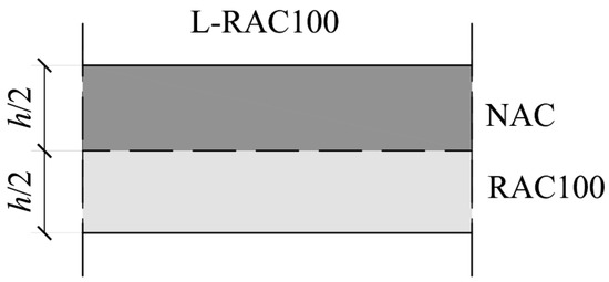
Figure 1.
Layered L-RAC100 slab section analyzed in the study.
Besides L-RAC100, three other concrete types were assessed, all with no layering (i.e., homogeneous): NAC, RAC50 (with 50% of coarse RCA) and RAC100 (with 100% coarse RCA). NAC and RAC100 were chosen as constitutive materials of L-RAC100, and RAC50 was chosen as an intermediate solution with the same overall percentage of coarse RCA as in L-RAC100 (50% NAC and 50% RAC100, by volume of the slab).
In OpenSees, all four concrete types were modeled using the TDConcreteMC10NL material. As the numerical formulation assumes that plane sections remain plane throughout the deformations of the element, a perfect bond was assumed between the NAC and RAC layers in the L-RAC100 slabs. In the case of a fresh-to-fresh connection in layered concrete, this assumption can be considered reasonable [13]. The mechanical stress–strain relationship for the TDConcreteMC10NL material is shown in Figure 2, along with its input parameters. The model comprises a nonlinear relationship in compression up to the compressive strength fc at peak strain εc0, determined by fc and the tangent modulus of elasticity Ec. After the peak, stress decreases linearly to the residual strength fcu at the ultimate strain εcu. In this study, considering concrete strength classes defined in the fib Model Code 2010 [21], the mean compressive strength fcm was adopted for fc, concrete modulus Ecm for Ec and a strain of 3.5‰ for εcu. In the post-cracking tensile region, TDConcreteMC10NL follows the relation proposed by Tamai et al. (1988) as:
where fct and εct0 are the axial tensile strength and strain at cracking, respectively, εct and σct are the tensile strain and corresponding stress, respectively, and bts is a tension-softening parameter (originally proposed as 0.4 by Tamai et al., 1988). In the current study, the mean axial tensile strength fctm was adopted for fct, according to the corresponding strength class [21], whereas the tension softening parameter bts was adopted as 0.8 for NAC and 0.9 for RAC50 and RAC100, according to a calibration performed on a database of experimental results, previously reported by Tošić and Kurama [6].
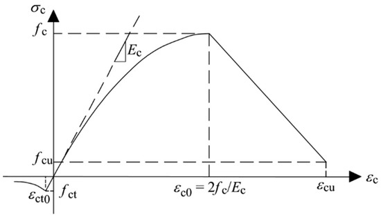
Figure 2.
Mechanical stress–strain relationship for the TDConcreteMC10NL material model.
The mean axial tensile strength fctm was calculated as a function of the compressive strength using the expression from the fib Model Code 2010 [21] as:
where fck is the characteristic strength of concrete, i.e., the 5%-fractile of compressive strength as per the fib Model Code 2010 [21]. Previous research has shown that the relationship between the compressive and tensile strengths for RCA is similar to that for NAC [26]. Therefore, Equation (2) was used for all of the concrete types in the study. However, the modulus of elasticity Ecm is highly affected by RCA [2], and thus an expression proposed by Tošić et al. [5] was used to calculate Ecm by adjusting the equation provided in the fib Model Code 2010 [21] as:
where RCA% is the mass percentage of coarse NA replacement with RCA and fcm is the mean compressive strength (= fck + 8 MPa).
For calculating the shrinkage strain and creep coefficient, the fib Model Code 2010 [21] was used. For RAC, the values were adjusted by correction factors proposed in [3,4] as:
where εcs,RAC is the total RAC shrinkage strain, εcs is the total shrinkage strain (basic + drying) calculated according to the fib Model Code 2010, φRAC is the total RAC creep coefficient, and φ is the total creep coefficient (basic + drying) calculated according to the fib Model Code 2010.
Considering the expressions and relations presented above, the total concrete strain for the TDConcreteMC10NL material is determined as
where εtot is the total strain, εm is the mechanical strain, εcbc and εcdc are the basic and drying creep strains, respectively, εcbs and εcds are the basic and drying shrinkage strains, respectively, t is the current time, ts is the age of concrete at the start of drying, and t0 is the age of concrete at loading. This strain is then used to check the equilibrium in each cross-section, determine the internal forces and check the convergence of the unbalanced force vector in the global analysis [17]. Thermal strains are not included in the formulation for TDConcreteMC10NL.
2.3. Formulation of the Parametric Study and Modeling
As explained in the previous subsection, four concrete types were considered in the analysis: NAC, RAC50, RAC100 and L-RAC100. Two statical systems were considered for the slabs, as shown in Figure 3: simply supported slabs (Figure 3a) and continuous slabs (modeled as one half of a symmetric three-span continuous slab, Figure 3b). Using OpenSees, each span was divided into 20 equal-length displacement-based dispBeamColumn elements [16].
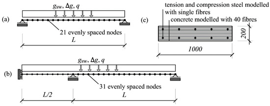
Figure 3.
Statical systems considered in the parametric study and cross-section discretization: (a) simply supported one-way slab, (b) continuous one-way slab, (c) discretization of slab cross-section into fibers.
Since the elements represented one-way slabs, a 1-m strip of slab was considered, i.e., cross-section width b was 1000 mm. The slab height was taken constant as h = 200 mm; other values for h were not analyzed, as Tošić and Kurama (2020) demonstrated that there is no detectable size effect in the deflections of NAC and RAC one-way slabs. Each element cross-section was discretized into 40 horizontal fibers, as shown in Figure 3c. In the case of L-RAC100, the top 20 fibers were designated as NAC, and the bottom 20 as RAC100.
Exposure class XC1 was assumed and the center of gravity of reinforcement (both tensile and compressive) was taken as d1 = 30 mm from the nearest concrete top/bottom face, i.e., the effective depth to the tension reinforcement was d = 170 mm, and concrete cover was assumed equal for all concrete types. This decision was based on a review of several studies that showed that, when RAC is produced with equal compressive strength as NAC, its carbonation resistance is similar or negligibly lower [27,28,29].
The span length, L, was varied by varying the span-to-effective depth ratio, L/d, between 20 and 30 for the simply supported slabs, and between 25 and 35 for the continuous slabs. In other words, the span lengths ranged from 3.4 to 5.1 m for the simply supported slabs and from 4.25 to 5.95 m for the continuous slabs. This was considered in six discrete increments of L/d, i.e., 20, 22, 24, 26, 28, 30 for the simply supported slabs and 25, 26, 28, 30, 32, 35 for the continuous slabs.
Two concrete strength classes, C25/30 and C30/37, were selected as being most appropriate for slabs in buildings and because of the widest availability of data for such concretes, necessary for LCA. Compressive strength was used to calculate the modulus of elasticity, tensile strength, shrinkage strain and creep coefficient, as described previously. For both RAC50 and RAC100, the modulus of elasticity, shrinkage strain and creep coefficient were adjusted using Equations (3)–(5). Relative humidity (RH) was adopted as 50% and 80% to simulate higher and lower amounts of shrinkage and creep deformations, respectively. The slabs were loaded by self-weight, gsw = 5 kN/m2, additional (superimposed) dead load, Δg = 3.0 kN/m2, and live load, q = 3 kN/m2. This means that the total ULS design load was qEd = 15.3 kN/m2 (1.35·gsw + 1.35·Δg + 1.50·q).
As a first step of the study, all of the slabs were designed for ULS flexural strength. This was done in the same way for all concrete types, as literature results show no difference in ULS flexural strength between NAC, RAC and layered RAC [14,30]. The calculated (i.e., required) ULS reinforcement As,ULS was adopted with no excess reinforcement, checking also for the minimum reinforcement ratio according to Eurocode 2 [31] (~0.013%). In the case of simply supported slabs, the reinforcement ratio, ρ, was assumed to be constant along the entire span. For the continuous slabs, the top (tension) reinforcement over the interior support was adopted over a length of 0.3·L on each side of the support, whereas the bottom reinforcement in the spans was adopted constant over the entire length in each span. Reinforcement was modeled with a bi-linear stress–strain relationship using the Steel01 material model in OpenSees, with a yield strength of 500 MPa, modulus of elasticity of 200 GPa and post-yield hardening modulus of 20 GPa.
As for deflection control, the live load q was considered with two distinct quasi-permanent coefficients of ψ2 = 0.0 and 0.6. This resulted in quasi-permanent loads of 8.0 and 9.8 kN/m2, and quasi-permanent-to-design load ratios, qqp/qEd, of 0.52 and 0.64, respectively. For all combinations, the characteristic load (gsw + Δg + q) was equal to 11 kN/m2.
With six L/d ratios for each set of parameters and four concrete types, a total of 192 cases were analyzed for each of the simply supported and continuous slab configurations, i.e., 384 calculations were performed in total. The parameters for all of these cases are provided as an Excel file in the Supplementary Material S1, available with the online version of the article. The time-dependent analyses were performed following a realistic loading procedure, as follows. Curing was assumed to continue until 7 days (i.e., start of shrinkage at 7 days, no loading); self-weight was applied at 14 days (i.e., removal of shoring); the additional dead load was applied at 60 days; the full live load was applied (to cause maximum cracking) at 180 days, and part of the live load was immediately removed, leaving only the quasi-permanent load on the slab. Each analysis was continued over a total duration of 25 years, which was adopted as a compromise between the longer computation time and the relatively small additional deflections expected beyond 25 years, as per the results of Tošić and Kurama (2020). Upon starting shrinkage (at 7 days), a global variable “setCreep” in OpenSees was set to 1 in order to begin accumulating shrinkage strains (i.e., the setCreep variable controls the accumulation of both creep and shrinkage in the analysis formulation). Following this, at each loading time (14, 60 and 180 days), a Static Analysis was performed first for the initial application of the intended load, followed by a time-dependent analysis to accumulate creep and additional shrinkage deformations using the setCreep variable. In each time-dependent analysis segment, the time steps were logarithmically spaced to capture the greater strain increments immediately after the end of curing and the initial application of an increment of load. The nonlinear solution algorithm in OpenSees was programmed to switch between the Newton, Modified Newton and Newton Line Search methods [22] to achieve convergence in each time step.
2.4. Parametric Analysis Results
As explained in the previous subsection, for each set of parameters, all four concrete types were designed identically for ULS, i.e., for each parameter set, the NAC, RAC50, RAC100 and L-RAC100 slabs had identical L/d ratios and reinforcement, and thus identical flexural ultimate and cracking strengths. This provided a foundation for their comparison in deflection behavior due to differences in the modulus of elasticity, creep, shrinkage and tension stiffening.
2.4.1. Simply Supported One-Way Slabs
The calculated maximum deflection (at midspan) behaviors of the simply supported slabs are shown in Figure 4, expressed in terms of a “normalized deflection”, a/alim, which represents the ratio of the maximum slab deflection to the limit (i.e., allowable) deflection for quasi-permanent load, equal to L/250 [21]. Importantly, deflections that remain below the allowable value would not have practical implications (i.e., they would not alter the design). The normalized deflection is plotted against the L/d ratio; and, once a/alim exceeds 1, the deflection limit is not satisfied. It can be seen from the figure that this generally happened for L/d ratios ranging between 22 and 25, i.e., for spans of 3.74 to 4.25 m.
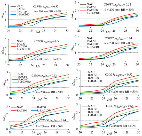
Figure 4.
Relationship between a/alim and L/d ratios for simply supported one-way slabs.
Figure 4 shows an expected change in deflection behavior moving from NAC to RAC50 and to RAC100, as the deflections and a/alim ratio increase in the same order. This is of course explained by the lower modulus of elasticity and tension stiffening and higher creep and shrinkage with increased amounts of RCA. The influence of creep and shrinkage is dominant as the differences are more pronounced for RH = 50%, for which both are larger than for RH = 80%. The effect of concrete strength is not significant, whereas the effect of the quasi-permanent-to-design load ratio can be noticed in a slight increase of differences between NAC, RAC50 and RAC100.
However, the most interesting results are those for layered RAC, i.e., the L-RAC100 slabs. It can be seen that L-RAC100 actually presents the best deflection behavior of all four concrete types and over the entire L/d range. These results can be explained by the fact that shrinkage in L-RAC100 is significantly different in the top and bottom halves of the cross-section height. Note that the TDConcreteMC10NL assumes constant shrinkage within a given volume of concrete material (i.e., there is no difference in the amount of shrinkage between the cover concrete and the core concrete). However, because of the layered placement of different materials, the lower half of the slab, made of RAC100, undergoes much higher shrinkage than the top half, made of NAC, leading to a shrinkage strain gradient over the cross-section height that produces negative curvature and a “camber” of the slab. The phenomenon results in shrinkage-induced self-equilibrating stresses in the cross-section, with compression at the bottom and tension at the top, and a corresponding linear strain distribution over the section height (i.e., plane sections assumption).
The beneficial effect of layered concrete is most visible for lower L/d ratios since the ratio of shrinkage-to-stress-induced strain (mechanical + creep) is the highest. This also causes the largest differences between L-RAC100 and NAC seen in the L/d range of 24 to 26. In some cases, the differential shrinkage prevents cracking due to load and causes much lower deflections of the L-RAC100 slabs. The proposed explanation can be seen clearly in Figure 5, where the top and bottom fiber strains are compared for NAC and L-RAC100 slabs with L/d = 20, for which this effect is the largest (the remaining parameters for the plotted case are C25/30, qqp/qEd = 0.64 and RH = 50%). The top fiber strains εc,1 are seen to be equal in both concretes because the top fibers in both are NAC. However, a stark difference exists for the bottom fiber strains εc,2, which are NAC and RAC100 in the NAC and L-RAC100 slabs, respectively, due to the much higher shrinkage in the bottom half of the L-RAC100 slab.
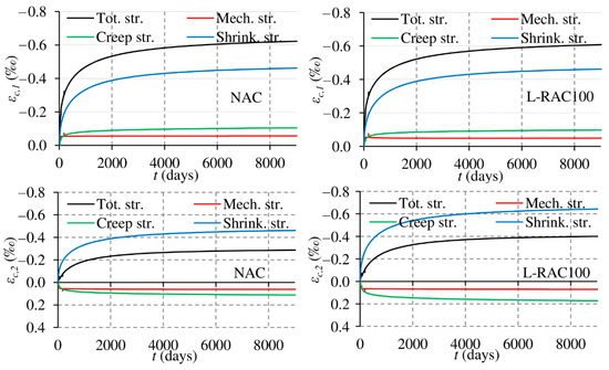
Figure 5.
Top (top) and bottom (bottom) fiber strains for NAC (left) and L-RAC100 (right) simply supported slabs with L/d = 20, C25/30, qqp/qEd = 0.64 and RH = 50%.
The above results provide several implications for deflection control. First, with identical ultimate and cracking strengths, homogeneous RAC slabs are limited to smaller L/d ratios with satisfied deflection control. For example, a case that can be considered typical for residential buildings, with C30/37, qqp/qEd = 0.52 and RH = 80%, simply supported slabs can be used up to L/d approximately 27.0, 26.5 and 26.0 utilizing NAC, RAC50 and RAC100, respectively. Even though these differences exist, they are not large, and the maximum L/d values are already high for simply supported slabs when considering code recommendations [31]. More importantly, though, the results provide a strong argument for the use of layered RAC as a way of achieving satisfactory ULS and SLS behavior (equal to or even superior to NAC), and at the same time a not insignificant utilization of RCA (equal to the amount used in RAC50, but with better deflection behavior).
2.4.2. Continuous One-Way Slabs
The results for the continuous one-way slabs are shown in Figure 6, taking into account maximum deflection obtained in the right span (Figure 3).
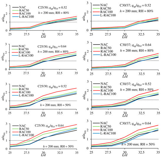
Figure 6.
Relationship between a/alim and L/d ratios for continuous one-way slabs.
The overall trends of the relationship between a/alim and L/d are the same as those for the simply supported slabs. As expected, deflections are satisfied up to higher L/d ratios, approximately 27–32, for the continuous slabs as compared with the simply supported slabs. As with the simply supported slabs, for homogenous concretes, the deflections increase in the order from NAC, RAC50 and RAC100, and the significance of the parameters remains similar: i.e., negligible influence of concrete class (for the two classes considered), small influence of load level and larger influence of relative humidity.
However, there is a notable difference in the trends for the L-RAC100 slabs. Specifically, the difference between NAC and L-RAC100 is much smaller for the continuous slabs than for the simply supported slabs. In fact, for higher L/d ratios (>30), the results show that deflections of the L-RAC100 slabs can be larger than those of the NAC slabs (even though the differences are small). A plausible reason for this is that in continuous slabs, above the support, the highly stressed compressive zone is at the bottom of the section made of RAC100. Consequently, as creep is higher in L-RAC100 than in NAC, negative curvatures develop, resulting in a reduction of the moment above the support in L-RAC100, while the positive moments in the span increase (i.e., moment redistribution between the support and the midspan). The increase in the span moments causes greater positive curvatures, leading to increased deflections. The differential shrinkage in the span still produces negative curvatures, but is no longer enough to offset the redistribution due to creep. This behavior tends to happen more in slabs with larger L/d ratios, where the mechanical strains are larger, and thus the creep strains are larger, leading to a smaller relative contribution from shrinkage, as illustrated in Figure 7 for continuous NAC and L-RAC100 slabs with L/d = 35, C25/30, qqp/qEd = 0.52 and RH = 80%. The moment diagrams for the two slabs are shown at 180 days (after only quasi-permanent load is left) and at the end of the analysis (25 years). Differences in the moment diagrams of the two slabs at 180 days are a consequence of increased shrinkage and cracking in the L-RAC100 slab, since the bottom half of the section is RAC100 with lower tension stiffening. It can be seen that between 180 days and 25 years, there is very little change in moment (i.e., moment redistribution) in the NAC slab, while a much larger decrease of negative moment above the support and increase of positive moment within the span occur for the L-RAC100 slab.
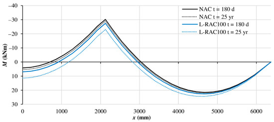
Figure 7.
Redistribution of bending moments over time for NAC and L-RAC100 continuous one-way slabs with L/d = 35, C25/30, qqp/qEd = 0.52 and RH = 80%.
Nonetheless, the deflections of the L-RAC100 slabs remain very close to those of the NAC slabs. Furthermore, they exceed NAC slab deflections only for higher L/d ratios for which deflection limits are already not satisfied, i.e., a/alim > 1. Hence, this effect can be considered to have little consequence for practical applications.
3. LCA of Homogeneous and Layered One-Way Slabs
In the previous section, the time-dependent deflection behavior of homogeneous and layered NAC and RAC slabs was presented. It is increasingly important to also assess the environmental impact of structures and structural members. Therefore, this section presents Life Cycle Assessment (LCA) results to complement the structural analyses of the previous section. In this way, a more holistic perspective can be gained on the benefits and limits of using RAC and layered slabs.
3.1. LCA Model
For the purposes of this study, a “cradle-to-gate” LCA was performed to assess and compare the environmental impacts of the studied one-way slabs (“cradle-to-gate” refers to the material production phase of the life cycle from the sourcing of the constituent materials to the production of concrete at a ready-mix plant). System boundaries are presented in Figure 8, where the dashed lines represent the phases that were excluded. Reinforcement production was excluded from the analysis, as all alternatives have the same type and amount of reinforcement. Concrete plasticizer (i.e., water reducer) production and water treatment were also excluded, as the energy input and emissions from these phases had negligible effect on the considered environmental impact categories.
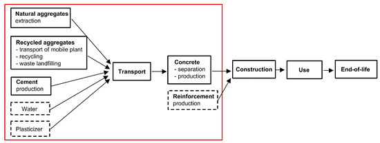
Figure 8.
Material production part of the slab life cycle.
Three alternatives were compared: NAC, RAC50 and L-RAC100 slabs. The RAC100 slab was not included because the intention was to compare the RAC alternatives with the same total amount of RCA in a unit volume of concrete (i.e., RAC50 and L-RAC100 slabs). As for exposure conditions, the slabs were assumed to be applied as building floors, exposed to in-door carbonation at RH = 50%; this is also the situation with the larger creep and shrinkage considered in the parametric numerical analyses. The FU was 1 m2 of slab with a height equal to 0.2 m. All three alternatives had the same strength and service life, but different deflections per FU, as shown in Figure 4 and Figure 6. Therefore, the obtained LCA results are interpreted considering their different deflection behaviors.
In order to be more representative and encompass possible variations, especially in RCA quality, instead of using three specific mixtures for NAC, RAC50 and RAC100, data on concrete mix designs were collected from published experimental research. Only research that contained the required input parameters for LCA—that is, amounts of all constituent materials, types of cement and aggregates, and compressive strength—were included in the database. In the selected data, water absorption of coarse RCA varied between 2.4% and 7.6 %, and the amount of plasticizer was below 2% of cement mass. Ordinary Portland cement was used in approximately 80% of the mixtures, whereas blended cements with up to 20% of mineral admixtures were used in the rest of the samples. For concrete strength class C25/30 (mean compressive strength between 33.0 and 37.9 MPa), the sample contained concrete mixture designs from the following sources:
- 32 NAC mixtures for the NAC slab [32,33,34,35,36,37,38,39,40,41,42,43,44,45,46,47,48,49,50,51,52,53,54]
- 32 RAC100 mixtures required for combination with NAC in the L-RAC100 slab [28,33,40,44,47,50,51,53,55,56,57,58,59,60,61,62,63,64,65,66,67,68,69,70,71]
- 23 RAC50 mixtures for the RAC50 slab [32,34,38,44,47,48,51,52,53,60,64,68,71,72,73,74,75]
Similarly, for concrete strength class C30/37 (mean compressive strength between 38.0 and 42.9 MPa), the sample contained materials from the following sources:
- 22 NAC mixtures for the NAC slab [34,52,56,57,58,61,62,63,64,66,67,71,76,77,78,79,80,81,82,83]
- 22 RAC100 mixtures required for combination with NAC in the L-RAC100 slab [34,36,39,50,52,57,58,59,61,63,73,79,80,82,83,84,85,86]
- 22 RAC50 mixtures for the RAC50 slab [33,34,36,42,50,52,60,61,62,63,67,77,79,80,82,83,87,88]
Mean and standard deviation values of the constituent material amounts and effective water-cement ratios, (w/c)eff for the selected mixtures are presented in Table 1 (in the case of RAC, (w/c)eff refers to the water-cement ratio disregarding the water needed for RCA to achieve a saturated surface dry condition that is satisfied either by mixing in additional batch water or by pre-soaking the RCA; in the case of NAC, (w/c)eff is equal to the apparent w/c ratio). For the C25/30 strength class, the RAC50 and RAC100 mixtures had slightly larger average cement contents (i.e., lower average (w/c)eff) than the NAC mixtures), but this difference was not evident for the C30/37 strength class. A larger variation was observed for the cement content than for the (w/c)eff ratio (except for RAC50, C25/30); however, the greater variability for the cement content in the NAC mix designs was not expected.

Table 1.
Mean values and standard deviations of constituent materials and effective water-cement ratio for considered concrete mixes.
An attributional approach was adopted for LCI modeling. This means that the inputs and outputs of phases shared by multiple products were allocated between the life cycles of these products. For example, the recycling of concrete from the parent NAC to RAC is shared by the life cycles of both materials, and therefore inputs and outputs of the recycling process have to be allocated between them. In this study, a relatively simple but common cut-off rule was applied for the allocation: demolition and selection (including transportation) were allocated to the parent NAC life cycle, whereas the recycling process itself was allocated to the RAC life cycle. LCI data were taken mostly from the Ecoinvent database [89,90,91] or from European organizations, except for RCA production. Serbian site-specific data were used for the RCA production phase because of the lack of this data in the Ecoinvent database [92]. Information about sources of LCI data and assumed transport types and distances is presented in Table 2 and Table 3, respectively. Recycling was assumed to be carried out in a mobile recycling plant that was transported to the demolition site at a distance of 50 km for each campaign of 2500 t. RCA was assumed to be transported over a distance not exceeding 20 km (a longer distance was considered too expensive in comparison with NA). Return distances were taken into account, as shown in Table 3.
Table 2.
Sources of LCI data.
Table 3.
Transport types and distances.
Impact category indicators related to green-house gasses and gasses released from burning fossil fuels were calculated using the CML (The Institute of Environmental Sciences of the Faculty of Sciences of Leiden University) baseline methodology [93], as follows: global warming potential (GWP), eutrophication potential (EP), acidification potential (AP) and photochemical-oxidant creation potential (POCP). Additionally, the abiotic depletion potential of fossil fuels (ADPFF) was calculated using the following heating values: 42.0 MJ/kg, 19.1 MJ/kg, 8.8 MJ/kg and 39.0 MJ/m3 for diesel, hard coal, soft coal and natural gas, respectively. The LCI and Life Cycle Impact Assessment (LCIA) calculations for each selected mixture were performed using an Excel-based software. A statistical analysis was performed on the impact indicators level.
3.2. LCIA Results
LCIA results in absolute figures are presented in Table 4 in terms of mean values and coefficients of variation (CoV). For the concrete strength class C25/30, the RAC50 and L-RAC100 slabs have practically identical impacts, slightly lower than the NAC slab, except for GWP. For the concrete strength class C30/37, the layered L-RAC100 slab has the best environmental performance, although the difference is small. The rather large CoV in the results was because the cement content in the considered mixtures varied significantly for the same strength class, as shown in Table 1. For all impact indicators, except ADPFF, cement is the largest determinant of environmental impact. Therefore, any variation in the amounts of cement used to produce the same compressive strength (e.g., for NAC and strength class C25/30, cement content varied between 300 and 410 kg/m3) will cause a large scatter of impact values.
Table 4.
Environmental impact indicators per functional unit (FU).
Furthermore, if cement content varies, water content must vary as well in order to achieve the same compressive strength; therefore, the selected mixtures used in the investigation had similar compressive strengths but different slump values. The large scatter of impact results could have been avoided by limiting the mixtures to a narrow range of slump, but in that case, the sample size would have been too small for a statistical analysis, despite the vast amount of research performed in this field.
Transport distance is the second largest determinant of concrete environmental impact, although to a much lesser extent than cement. For the C25/30 strength class, the slightly lower average cement content for NAC was compensated with larger transport distances of natural aggregates compared with RCA. For the C30/37 strength class, the average cement content of the considered mixtures was very similar, but smaller transport distances of RCA caused lower impacts of the alternatives containing it. Even when the FU has the same volume for the NAC and RAC alternatives, which is possible only if RAC deflection behavior is improved and equal to NAC behavior, it is hard to obtain benefits from RAC using the attributional model if transport distances of the aggregates are equal [96]. Therefore, it is very important that recycling plants are located as close as possible to the construction site, not only from the environmental point of view, but also to make the RAC alternative competitive to NAC in terms of costs.
Average values of RAC50 and L-RAC100 slab impact indicators expressed in relative to average values of NAC slab impact indicators for concrete strength classes C25/30 and C30/37 are presented in Figure 9 and Figure 10, respectively. Compared with the RAC50 slab, the L-RAC100 slab has similar environmental impacts but improved deflection behavior for both statical systems and both strength classes, as was shown in Figure 4 and Figure 6 for RH = 50%. This means that the layered L-RAC100 slab can be applied for longer spans than the RAC50 slab with the same concrete volume and reinforcement amount, without affecting the environmental impacts. Compared with the NAC slab, the L-RAC100 slab has lower environmental impacts (except for GWP, which is practically equal), and the deflection behavior is at least equal to that of the NAC slab (for simply supported slabs it is even better), as was shown in Figure 4 and Figure 6. If homogeneous NAC and RAC100 slabs were compared using a similar LCA model, all impacts of the RAC100 slab would be higher than those of the NAC slab by approximately 10%, due to larger RAC slab deflections (which means a larger FU is required for RAC100), as shown by Marinković et al. [11].
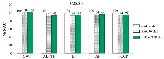
Figure 9.
Environmental impact indicators of RAC50 and L-RAC100 slabs relative to NAC slab, with C25/30 (mean values).
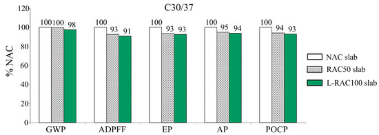
Figure 10.
Environmental impact indicators of RAC50 and L-RAC100 slabs relative to NAC slab, with C30/37 (mean values).
The L-RAC100 slab fulfills the same functional requirements regarding strength, serviceability and service life as the NAC slab, with lower life cycle environmental impact and the same volume of concrete and reinforcement amount. It could be argued that the main environmental impacts are only slightly lower and GWP is practically equal. However, every RAC alternative brings an additional environmental credit that is not quantified in the baseline CML methodology: namely, the avoidance of waste landfilling and the enabled reuse of recycled concrete waste in new applications. Minimizing resource use and waste generation helps create a circular flow of resources and materials, and contributes to closing the loop for concrete construction. Having all this in mind, it can be concluded that, between the compared alternatives, the layered L-RAC100 slab exhibits the best overall performance, taking into account strength, deflections, service life and impact on the environment. Although the results presented in this study are based only on numerical analyses and assumptions adopted in the LCA model, they provide a strong impetus for further experimental research on layered NAC and RAC slabs as a structurally and environmentally advantageous solution.
4. Conclusions
This paper presented the results of a numerical structural deflection and environmental assessment of layered and homogeneous NAC and RAC one-way slabs. For this purpose, homogeneous concrete slabs with 0% (NAC), 50% (RAC50) and 100% (RAC100) of coarse RCA were considered, as well as a layered L-RAC100 slab with the bottom and top halves produced from RAC100 and NAC, respectively. The structural analysis was performed in OpenSees using a recently developed material model for the time-dependent deflection behavior of concrete. A parametric study was performed considering different slab statical systems, span length-to-depth L/d ratios, concrete strength classes, service loads and ambient conditions. Furthermore, a “cradle-to-gate” LCA was performed for the homogeneous NAC and RAC50 slabs and the layered L-RAC100 slab to determine the environmental impact of each alternative. The LCA was performed on a database of actual laboratory mix designs collected from literature considering the concrete strength classes used in the parametric analyses. Based on the obtained results, the following conclusions are drawn:
- Within the considered parametric study, the largest influence on the time-dependent service-load deflection behavior of one-way slabs was exerted by relative humidity, as its decrease significantly increased creep and shrinkage; the quasi-permanent-to-design load ratio had a moderate effect on the results, whereas the change in concrete strength class from C25/30 to C30/37 did not have a significant effect.
- For both simply supported and continuous homogeneous one-way slabs, the deflections increased in the order of NAC, RAC50 and RAC100, which was expected due to the increased creep and shrinkage with increased amounts of RCA. However, the layered L-RAC100 slab exhibited a deflection behavior practically equal to NAC. This was explained by the differential shrinkage between the bottom RAC100 and the top NAC layer; analyzing cross-sectional strains and curvatures, it was shown that the larger shrinkage of the bottom RAC100 layer compensated for part of the load-induced deflections.
- The “cradle-to-gate” LCA showed that the RAC50 and L-RAC100 slabs have an equal or better environmental performance than the NAC slab. This means that, considering both structural and environmental assessments, L-RAC100 slabs can be viewed as an improved solution, compared with NAC slabs.
It should be noted that the presented structural analysis results are based on a numerical study and may be only valid for the ranges of parameters considered. Furthermore, the LCA results are dependent on the reliability of the concrete mixture design data collected from the literature and assumed scenario in the LCA model. Therefore, further experimental investigation into the behavior of layered NAC and RAC slabs is required. Nonetheless, the results of this study can provide a first step toward the practical implementation of structurally and environmentally beneficial layered concrete slabs.
Supplementary Materials
The following are available online at https://www.mdpi.com/2071-1050/12/24/10278/s1: Excel file with input data for the parametric numerical study.
Author Contributions
Conceptualization, N.T. and Y.K.; methodology N.T, S.M. and Y.K.; software, N.T.; data curation, N.T.; writing—original draft preparation, N.T.; writing—review and editing, S.M. and Y.K.; visualization, N.T.; funding acquisition, N.T. All authors have read and agreed to the published version of the manuscript.
Funding
This study has received funding from the European Union’s Horizon 2020 research and innovation programme under the Marie Skłodowska-Curie grant agreement no. 836270 and from the United States Department of State through the Fulbright Visiting Scholar Grant “Optimization of Stratified Recycled Concrete Structures Based on Numerical Analyses and Life Cycle Assessment.” Any opinions, findings, conclusions, and/or recommendations in the paper are those of the authors and do not necessarily represent the views of the funding organizations.
Conflicts of Interest
The authors declare no conflict of interest.
References
- Tam, V.W.Y.; Soomro, M.; Evangelista, A.C.J. A review of recycled aggregate in concrete applications (2000–2017). Constr. Build. Mater. 2018, 172, 272–292. [Google Scholar] [CrossRef]
- Silva, R.V.; de Brito, J.; Dhir, R.K. Establishing a relationship between the modulus of elasticity and compressive strength of recycled aggregate concrete. J. Clean. Prod. 2016, 112, 2171–2186. [Google Scholar] [CrossRef]
- Tošić, N.; de la Fuente, A.; Marinković, S. Shrinkage of recycled aggregate concrete: Experimental database and application of fib Model Code 2010. Mater. Struct. Constr. 2018, 51, 126. [Google Scholar] [CrossRef]
- Tošić, N.; de la Fuente, A.; Marinković, S. Creep of recycled aggregate concrete: Experimental database and creep prediction model according to the fib Model Code 2010. Constr. Build. Mater. 2019, 195, 590–599. [Google Scholar] [CrossRef]
- Tošić, N.; Marinković, S.; de Brito, J. Deflection control for reinforced recycled aggregate concrete beams: Experimental database and extension of the fib Model Code 2010 model. Struct. Concr. 2019, 1–15. [Google Scholar] [CrossRef]
- Tošić, N.; Kurama, Y. Parametric numerical study on service-load deflections of reinforced recycled aggregate concrete slabs and beams based on fib Model Code 2010. Struct. Concr. 2020. [Google Scholar] [CrossRef]
- ISO 14041. Environmental Management—Life Cycle Assessment: Goal and Scope Definition and Inventory Analysis; International Organization for Standardization: Geneva, Switzerland, 2006. [Google Scholar]
- Fraj, A.B.; Idir, R. Concrete based on recycled aggregates—Recycling and environmental analysis: A case study of Paris’ region. Constr. Build. Mater. 2017, 157, 952–964. [Google Scholar] [CrossRef]
- Kleijer, A.L.; Lasvaux, S.; Citherlet, S.; Viviani, M. Product-specific Life Cycle Assessment of ready mix concrete: Comparison between a recycled and an ordinary concrete. Resour. Conserv. Recycl. 2017, 122, 210–218. [Google Scholar] [CrossRef]
- Knoeri, C.; Sanyé-Mengual, E.; Althaus, H.-J. Comparative LCA of recycled and conventional concrete for structural applications. Int. J. Life Cycle Assess. 2013, 18, 909–918. [Google Scholar] [CrossRef]
- Marinković, S.; Dragaš, J.; Ignjatović, I.; Tošić, N. Environmental assessment of green concretes for structural use. J. Clean. Prod. 2017, 154, 633–649. [Google Scholar] [CrossRef]
- Dobbelaere, G.; de Brito, J.; Evangelista, L. Definition of an equivalent functional unit for structural concrete incorporating recycled aggregates. Eng. Struct. 2016, 122, 196–208. [Google Scholar] [CrossRef]
- Chan, R.; Liu, X.; Galobardes, I. Parametric study of functionally graded concretes incorporating steel fibres and recycled aggregates. Constr. Build. Mater. 2020, 242, 118186. [Google Scholar] [CrossRef]
- Xiao, J.; Sun, C.; Jiang, X. Flexural behaviour of recycled aggregate concrete graded slabs. Struct. Concr. 2015, 16, 249–261. [Google Scholar] [CrossRef]
- Liu, X.; Yan, M.; Galobardes, I.; Sikora, K. Assessing the potential of functionally graded concrete using fibre reinforced and recycled aggregate concrete. Constr. Build. Mater. 2018, 171, 793–801. [Google Scholar] [CrossRef]
- McKenna, F. OpenSees: A framework for earthquake engineering simulation. Comput. Sci. Eng. 2011. [Google Scholar] [CrossRef]
- Knaack, A.M.; Kurama, Y.C. Modeling Time-Dependent Deformations: Application for Reinforced Concrete Beams with Recycled Concrete Aggregates. ACI Struct. J. 2018, 115, 175–190. [Google Scholar] [CrossRef]
- ACI 209R-92. Prediction of Creep, Shrinkage, and Temperature Effects in Concrete Structures; American Concrete Institute: Farmington Hills, MI, USA, 1992. [Google Scholar]
- Tamai, S.; Shima, H.; Izumo, J.; Okamura, H. Average stress-strain relationship in post yield range of steel bar in concrete. Concr. Libr. JSCE 1988, 11, 117–129. [Google Scholar]
- Knaack, A.M.; Kurama, Y.C. Effect of recycled concrete coarse aggregates on service-load deflections of reinforced concrete columns. Eng. Struct. 2020, 204, 109955. [Google Scholar] [CrossRef]
- FIB. Fib Model Code for Concrete Structures 2010; International Federation for Structural Concrete (FIB): Lausanne, Switzerland, 2013; ISBN 9783433604090. [Google Scholar]
- Mazzoni, S.; McKenna, F.; Scott, M.H.; Fenves, G.L. OpenSees command language manual. Pac. Earthq. Eng. Res. Cent. 2006. Available online: https://opensees.berkeley.edu/OpenSees/manuals/usermanual/OpenSeesCommandLanguageManualJune2006.pdf (accessed on 8 December 2020).
- Mohd-Yassin, M.H.; Filippou, F.C. Nonlinear analysis of prestressed concrete structures. In Proceedings of the Structures Congress XII, Atlanta, GA, USA, 24–27 April 1994. [Google Scholar]
- Knaack, A.M. Sustainable concrete Structures Using Recycled Concrete Aggregate: Short-Term and Long-Term Behavior Considering Material Variability. Doctoral Dissertation, University of Notre Dame, Notre Dame, IN, USA, 2013. [Google Scholar]
- Tošić, N.; Knaack, A.; Kurama, Y. Supporting Documentation for Time-Dependent Concrete Material Models in OpenSees. 2020. Available online: https://data.mendeley.com/datasets/z4gxnhchky/3 (accessed on 9 December 2020). [CrossRef]
- Silva, R.V.; de Brito, J.; Dhir, R.K. Tensile strength behaviour of recycled aggregate concrete. Constr. Build. Mater. 2015, 83, 108–118. [Google Scholar] [CrossRef]
- Levy, S.M.; Helene, P. Durability of recycled aggregates concrete: A safe way to sustainable development. Cem. Concr. Res. 2004, 34, 1975–1980. [Google Scholar] [CrossRef]
- Limbachiya, M.; Meddah, M.S.; Ouchagour, Y. Use of recycled concrete aggregate in fly-ash concrete. Constr. Build. Mater. 2012, 27, 439–449. [Google Scholar] [CrossRef]
- Silva, R.V.; Neves, R.; de Brito, J.; Dhir, R.K. Carbonation behaviour of recycled aggregate concrete. Cem. Concr. Compos. 2015, 62, 22–32. [Google Scholar] [CrossRef]
- Tošić, N.; Marinković, S.; Ignjatović, I. A database on flexural and shear strength of reinforced recycled aggregate concrete beams and comparison to Eurocode 2 predictions. Constr. Build. Mater. 2016, 127, 932–944. [Google Scholar] [CrossRef]
- EN 1992-1-1. Eurocode 2: Design of Concrete Structures—Part 1-1: General Rules and Rules for Buildings; CEN: Brussels, Belgium, 2004; ISBN 978-0-580-62664-7. [Google Scholar]
- Arezoumandi, M.; Volz, J.; Khayat, K. Effect of Recycled Concrete Aggregate Replacement Level on Shear Strength of Reinforced Concrete Beams. ACI Mater. J. 2015, 112, 559–567. [Google Scholar] [CrossRef]
- Barbudo, A.; De Brito, J.; Evangelista, L.; Bravo, M.; Agrela, F. Influence of water-reducing admixtures on the mechanical performance of recycled concrete. J. Clean. Prod. 2013. [Google Scholar] [CrossRef]
- Beltrán, M.G.; Barbudo, A.; Agrela, F.; Galvín, A.P.; Jiménez, J.R. Effect of cement addition on the properties of recycled concretes to reach control concretes strengths. J. Clean. Prod. 2014, 79, 124–133. [Google Scholar] [CrossRef]
- Dilbas, H.; Şimşek, M.; Çakir, Ö. An investigation on mechanical and physical properties of recycled aggregate concrete (RAC) with and without silica fume. Constr. Build. Mater. 2014. [Google Scholar] [CrossRef]
- Etxeberria, M.; Vázquez, E.; Marí, A.; Barra, M. Influence of amount of recycled coarse aggregates and production process on properties of recycled aggregate concrete. Cem. Concr. Res. 2007, 37, 735–742. [Google Scholar] [CrossRef]
- Folino, P.; Xargay, H. Recycled aggregate concrete—Mechanical behavior under uniaxial and triaxial compression. Constr. Build. Mater. 2014, 56, 21–31. [Google Scholar] [CrossRef]
- Gholampour, A.; Ozbakkaloglu, T. Time-dependent and long-term mechanical properties of concretes incorporating different grades of coarse recycled concrete aggregates. Eng. Struct. 2018, 157, 224–234. [Google Scholar] [CrossRef]
- Arlindo, G. Influence of recycled concrete aggregates on concrete durability. In Proceedings of the International RILEM Conference on the Use of Recycled Materials in Buildings and Structures, Barcelona, Spain, 8–11 November 2004. [Google Scholar]
- Ignjatović, I.; Marinković, S.; Tošić, N. Shear behaviour of recycled aggregate concrete beams with and without shear reinforcement. Eng. Struct. 2017, 141, 386–401. [Google Scholar] [CrossRef]
- Kim, S.W.; Yun, H. Do Influence of recycled coarse aggregates on the bond behavior of deformed bars in concrete. Eng. Struct. 2013. [Google Scholar] [CrossRef]
- Kou, S.C.; Poon, C.S.; Dixon, C.; Chan, D. Influence of fly ash as cement replacement on the properties of recycled aggregate concrete. J. Mater. Civ. Eng. 2007, 19, 709–717. [Google Scholar] [CrossRef]
- Kou, S.C.; Poon, C.S. Long-term mechanical and durability properties of recycled aggregate concrete prepared with the incorporation of fly ash. Cem. Concr. Compos. 2013, 37, 12–19. [Google Scholar] [CrossRef]
- Malešev, M.; Radonjanin, V.; Marinković, S. Recycled concrete as aggregate for structural concrete production. Sustainability 2010, 2, 1204–1225. [Google Scholar] [CrossRef]
- Pacheco, J.; de Brito, J.; Chastre, C.; Evangelista, L. Uncertainty of shear resistance models: Influence of recycled concrete aggregate on beams with and without shear reinforcement. Eng. Struct. 2019, 109905. [Google Scholar] [CrossRef]
- Pedro, D.; De Brito, J.; Evangelista, L. Influence of the use of recycled concrete aggregates from different sources on structural concrete. Constr. Build. Mater. 2014. [Google Scholar] [CrossRef]
- Reis, N.; de Brito, J.; Correia, J.R.; Arruda, M.R.T. Punching behaviour of concrete slabs incorporating coarse recycled concrete aggregates. Eng. Struct. 2015, 100, 238–248. [Google Scholar] [CrossRef]
- De Juan, M.S.; Gutierrez, P.A.; Gutiérrez, P.A. Influence of recycled aggregate quality on concrete properties. In Proceedings of the International Rilem Conference on the Use of Recycled Materials in Buildings and Structures, Barcelona, Spain, 8–11 November 2004; pp. 545–553. [Google Scholar]
- Soares, D.; De Brito, J.; Ferreira, J.; Pacheco, J. Use of coarse recycled aggregates from precast concrete rejects: Mechanical and durability performance. Constr. Build. Mater. 2014, 71, 263–272. [Google Scholar] [CrossRef]
- Thomas, C.; Setién, J.; Polanco, J.A.; Alaejos, P.; Sánchez De Juan, M. Durability of recycled aggregate concrete. Constr. Build. Mater. 2013. [Google Scholar] [CrossRef]
- Tošić, N.; Marinković, S.; Dašić, T.; Stanić, M. Multicriteria optimization of natural and recycled aggregate concrete for structural use. J. Clean. Prod. 2015, 87, 766–776. [Google Scholar] [CrossRef]
- Ridzuan, A.R.M.; Ibrahim, A.; Ismail, A.M.M.; Diah, A.B.M. Durablity performance of recycled aggregate concrete. In Proceedings of the International Conference on Achieving Sustainability in Construction, Dundee, UK, 5–6 July 2005. [Google Scholar]
- Zhou, C.; Chen, Z. Mechanical properties of recycled concrete made with different types of coarse aggregate. Constr. Build. Mater. 2017, 134, 497–506. [Google Scholar] [CrossRef]
- Dos Santos, J.R.; Branco, F.; De Brito, J. Mechanical properties of concrete with coarse recycled aggregates. Struct. Eng. Int. J. Int. Assoc. Bridg. Struct. Eng. 2004, 14, 213–215. [Google Scholar] [CrossRef]
- Akbarnezhad, A.; Ong, K.C.G.; Zhang, M.H.; Tam, C.T.; Foo, T.W.J. Microwave-assisted beneficiation of recycled concrete aggregates. Constr. Build. Mater. 2011. [Google Scholar] [CrossRef]
- Barra, M.; Vázquez, E. Properties of concretes with recycled aggregates: Influence of properties of the aggregates and their interpretation. In Proceedings of the International Symposium Sustainable Construction: Use of Recycled Concrete Aggregate, London, UK, 11–12 November 1998. [Google Scholar]
- Berndt, M.L. Properties of sustainable concrete containing fly ash, slag and recycled concrete aggregate. Constr. Build. Mater. 2009. [Google Scholar] [CrossRef]
- Butler, L.; West, J.S.; Tighe, S.L. The effect of recycled concrete aggregate properties on the bond strength between RCA concrete and steel reinforcement. Cem. Concr. Res. 2011, 41, 1037–1049. [Google Scholar] [CrossRef]
- Dhir, R.K.; Paine, K.A.; O’Leary, S. Use of recycled concrete aggregate in concrete pavement construction: A case study. In Proceedings of the Sustainable Waste Management, Proceedings of the International Symposium, Dundee, UK, 9–11 September 2003. [Google Scholar]
- Ferreira, L.; de Brito, J.; Barra, M. Influence of the pre-saturation of recycled coarse concrete aggregates on concrete properties. Mag. Concr. Res. 2011, 63, 617–627. [Google Scholar] [CrossRef]
- Fonseca, N.; De Brito, J.; Evangelista, L. The influence of curing conditions on the mechanical performance of concrete made with recycled concrete waste. Cem. Concr. Compos. 2011, 33, 637–643. [Google Scholar] [CrossRef]
- Guerra, M.; Ceia, F.; De Brito, J.; Júlio, E. Anchorage of steel rebars to recycled aggregates concrete. Constr. Build. Mater. 2014, 72, 113–123. [Google Scholar] [CrossRef]
- Kou, S.C.; Poon, C.S.; Agrela, F. Comparisons of natural and recycled aggregate concretes prepared with the addition of different mineral admixtures. Cem. Concr. Compos. 2011, 33, 788–795. [Google Scholar] [CrossRef]
- Kou, S.C.; Poon, C.S.; Etxeberria, M. Residue strength, water absorption and pore size distributions of recycled aggregate concrete after exposure to elevated temperatures. Cem. Concr. Compos. 2014, 53, 73–82. [Google Scholar] [CrossRef]
- Lin, Y.H.; Tyan, Y.Y.; Chang, T.P.; Chang, C.Y. An assessment of optimal mixture for concrete made with recycled concrete aggregates. Cem. Concr. Res. 2004. [Google Scholar] [CrossRef]
- Nagataki, S.; Gokce, A.; Saeki, T.; Hisada, M. Assessment of recycling process induced damage sensitivity of recycled concrete aggregates. Cem. Concr. Res. 2004. [Google Scholar] [CrossRef]
- Pacheco, J.; de Brito, J.; Chastre, C.; Evangelista, L. Experimental investigation on the variability of the main mechanical properties of concrete produced with coarse recycled concrete aggregates. Constr. Build. Mater. 2019, 201, 110–120. [Google Scholar] [CrossRef]
- Poon, C.S.; Shui, Z.H.; Lam, L.; Fok, H.; Kou, S.C. Influence of moisture states of natural and recycled aggregates on the slump and compressive strength of concrete. Cem. Concr. Res. 2004, 34, 31–36. [Google Scholar] [CrossRef]
- Tangchirapat, W.; Rattanashotinunt, C.; Buranasing, R.; Jaturapitakkul, C. Influence of fly ash on slump loss and strength of concrete fully incorporating recycled concrete aggregates. J. Mater. Civ. Eng. 2013. [Google Scholar] [CrossRef]
- Wang, Z.; Wang, L.; Cui, Z.; Zhou, M. Effect of recycled coarse aggregate on concrete compressive strength. Trans. Tianjin Univ. 2011. [Google Scholar] [CrossRef]
- Yang, K.H.; Chung, H.S.; Ashour, A.F. Influence of type and replacement level of recycled aggregates on concrete properties. ACI Mater. J. 2008, 105, 289–296. [Google Scholar] [CrossRef]
- Corinaldesi, V. Mechanical and elastic behaviour of concretes made of recycled-concrete coarse aggregates. Constr. Build. Mater. 2010, 24, 1616–1620. [Google Scholar] [CrossRef]
- González-Fonteboa, B.; Martínez-Abella, F.; Eiras-López, J.; Seara-Paz, S. Effect of recycled coarse aggregate on damage of recycled concrete. Mater. Struct. Constr. 2011. [Google Scholar] [CrossRef]
- Khodair, Y.; Bommareddy, B. Self-consolidating concrete using recycled concrete aggregate and high volume of fly ash, and slag. Constr. Build. Mater. 2017. [Google Scholar] [CrossRef]
- Sadati, S.; Arezoumandi, M.; Khayat, K.H.; Volz, J.S. Shear performance of reinforced concrete beams incorporating recycled concrete aggregate and high-volume fly ash. J. Clean. Prod. 2016, 115, 284–293. [Google Scholar] [CrossRef]
- Adams, M.P.; Fu, T.; Cabrera, A.G.; Morales, M.; Ideker, J.H.; Isgor, O.B. Cracking susceptibility of concrete made with coarse recycled concrete aggregates. Constr. Build. Mater. 2016. [Google Scholar] [CrossRef]
- Kou, S.C.; Poon, C.S.; Chan, D. Influence of fly ash as a cement addition on the hardened properties of recycled aggregate concrete. Mater. Struct. 2008, 41, 1191–1201. [Google Scholar] [CrossRef]
- Corinaldesi, V. Structural concrete prepared with coarse recycled concrete aggregate: From investigation to design. Adv. Civ. Eng. 2011. [Google Scholar] [CrossRef]
- Matias, D.; De Brito, J.; Rosa, A.; Pedro, D. Mechanical properties of concrete produced with recycled coarse aggregates—Influence of the use of superplasticizers. Constr. Build. Mater. 2013. [Google Scholar] [CrossRef]
- Ozbakkaloglu, T.; Gholampour, A.; Xie, T. Mechanical and durability properties of recycled aggregate concrete: Effect of recycled aggregate properties and content. J. Mater. Civ. Eng. 2018. [Google Scholar] [CrossRef]
- Razaqpur, A.G.; Fathifazl, G.; Isgor, B.; Abbas, A.; Fournier, B.; Foo, S. How to produce high quality concrete mixes with recycled concrete aggregate. Int. Conf. Waste Eng. Manag. ICWEM 2010, 2010, 11–35. [Google Scholar]
- Xiao, J.; Zhang, K.; Akbarnezhad, A. Variability of stress-strain relationship for recycled aggregate concrete under uniaxial compression loading. J. Clean. Prod. 2018. [Google Scholar] [CrossRef]
- Soares, D.; De Brito, J.; Ferreira, J.; Pacheco, J. In situ materials characterization of full-scale recycled aggregates concrete structures. Constr. Build. Mater. 2014. [Google Scholar] [CrossRef]
- Abbas, A.; Fathifazl, G.; Isgor, O.B.; Razaqpur, A.G.; Fournier, B.; Foo, S. Durability of recycled aggregate concrete designed with equivalent mortar volume method. Cem. Concr. Compos. 2009. [Google Scholar] [CrossRef]
- Gurdián, H.; García-Alcocel, E.; Baeza-Brotons, F.; Garcés, P.; Zornoza, E. Corrosion behavior of steel reinforcement in concrete with recycled aggregates, fly ash and spent cracking catalyst. Materials 2014, 4, 3176–3197. [Google Scholar] [CrossRef] [PubMed]
- Kurda, R.; de Brito, J.; Silvestre, J.D. Combined economic and mechanical performance optimization of recycled aggregate concrete with high volume of fly ash. Appl. Sci. 2018, 8, 1189. [Google Scholar] [CrossRef]
- Domingo-Cabo, A.; Lázaro, C.; López-Gayarre, F.; Serrano-López, M.A.; Serna, P.; Castaño-Tabares, J.O. Creep and shrinkage of recycled aggregate concrete. Constr. Build. Mater. 2009, 23, 2545–2553. [Google Scholar] [CrossRef]
- Knaack, A.M.; Kurama, Y.C. Sustained Service Load Behavior of Concrete Beams with Recycled Concrete Aggregates. ACI Struct. J. 2015, 112, 565–578. [Google Scholar] [CrossRef]
- Dones, R.; Bauer, C.; Bolliger, R.; Burger, B.; Heck, T.; Röder, A.; Paul Scherrer Institut; Emmenegger, M.F.; Frischknecht, R.; Jungbluth, N.; et al. Life Cycle Inventories of Energy Systems: Results for Current Systems in Switzerland and Other UCTE Countries; Paul Scherer Institut Villigen, Swiss Centre for Life Cycle Inventories: Dübendorf, Switzerland, 2007. [Google Scholar]
- Kellenberger, D.; Althaus, H.-J.; Jungbluth, N.; Künninger, T.; Lehmann, M.; Thalmann, P. Life Cycle inventories of Building Products; EMPA Dübendorf, Swiss Centre for Life Cycle Inventories: Dübendorf, Switzerland, 2007. [Google Scholar]
- Spielmann, M.; Bauer, C.; Dones, R.; Tuchschmid, M. Transport Services. Ecoinvent report no. 14. Swiss Cent. Life Cycle Invent. 2007. [Google Scholar] [CrossRef]
- Marinković, S.; Radonjanin, V.; Malešev, M.; Lukić, I. Life Cycle Environmental Impact Assessment of Concrete. In Sustainability of Constructions—Integrated Approach to Life-time Structural Engineering. COST action C25. Proceedings of Seminar; Bragança, L., Koukkari, H., Blok, R., Gervasio, H., Veljković, M., Plewako, Z., Landolfo, R., Ungureanu, V., Silva, L.S., Haller, P., Eds.; Addprint AG: Possendorf, Germany, 2008; pp. 3.5–3.16. [Google Scholar]
- Guinée, J.B.; Gorrée, M.; Heijungs, R.; Huppes, G.; Kleijn, R.; de Koning, A.; van Oers, L.; Wegener Sleeswijk, A.; Suh, S.; Udo de Haes, H.A.; et al. Handbook on Life Cycle Assessment. Operational Guide to the ISO Standards. I: LCA in Perspective. IIa: Guide. IIb: Operational Annex. III: Scientific Background; Kluwer Academic Publishers: Dordrecht, The Netherlands, 2002; ISBN 1-4020-0228-9. [Google Scholar]
- CEMBUREAU. Environmental Product Declaration (EPD) according to EN 15804 and ISO 14025: Portland Cement (CEM I) produced in Europe; CEMBUREAU—European Cement Association: Brussels, Belgium, 2015. [Google Scholar]
- CEMBUREAU. Environmental Product Declaration (EPD) according to EN 15804 and ISO 14025: Portland-Composite Cement (CEM II) produced in Europe; CEMBUREAU—European Cement Association: Brussels, Belgium, 2015. [Google Scholar]
- Marinković, S.; Radonjanin, V.; Malešev, M.; Ignjatović, I. Comparative environmental assessment of natural and recycled aggregate concrete. Waste Manag. 2010, 30, 2255–2264. [Google Scholar] [CrossRef]


Publisher’s Note: MDPI stays neutral with regard to jurisdictional claims in published maps and institutional affiliations. |
© 2020 by the authors. Licensee MDPI, Basel, Switzerland. This article is an open access article distributed under the terms and conditions of the Creative Commons Attribution (CC BY) license (http://creativecommons.org/licenses/by/4.0/).