Abstract
In response to the “carbon peak and carbon neutrality” strategy, industrial energy conservation has become increasingly important. Interior Permanent Magnet Synchronous Motors (IPMSMs) exhibit significant potential for efficient flux-weakening control due to their asymmetric rotor reluctance. However, conventional control strategies often cause instability during transitions across speed zones. This paper proposes a novel adaptive fuzzy-based smooth transition strategy to address this issue. First, a composite control framework integrating Maximum Torque per Ampere (MTPA) and leading-angle control is established to enhance flux-weakening capability. Then, within this framework, adaptive fuzzy controllers are designed for different weakening zones, incorporating a Lyapunov-based parameter adaptation mechanism for real-time compensation. Simulation results demonstrate that the proposed strategy achieves smooth switching across the entire speed range of IPMSMs. Quantitatively, it reduces speed overshoot by 5–15%, suppresses torque ripple by over 10%, and virtually eliminates switching current pikes compared to conventional methods, thereby significantly improving system dynamic performance and operational reliability.
1. Introduction
With the rapid development of new energy vehicles and variable-frequency home appliances, performance requirements for drive systems continue to rise. Achieving stable and efficient operation of permanent magnet synchronous motors (PMSMs) across a wide speed range has become a current research hotspot [1]. Among these applications, electric vehicle (EV) traction systems impose particularly stringent requirements on motor drives, including high torque density for acceleration, a wide constant-power speed range for cruising, and robust stability under rapidly changing loads. The Interior Permanent Magnet Synchronous Motors (IPMSMs), with their inherent flux-weakening capability, are thus a preferred choice for EV traction. However, the transition between different control zones (e.g., constant torque and flux-weakening regions) during aggressive driving cycles can induce torque ripples or speed oscillations, adversely affecting vehicle drivability and passenger comfort. Therefore, developing a smooth and adaptive transition strategy is of paramount importance for high-performance EV traction systems. As the core executive component of power systems, motor control performance directly impacts the reliability and safety of the entire system. Motor control strategies have continuously evolved, from early variable-frequency variable-voltage control to today’s direct torque control and vector control. To meet the demands of high-speed operation, traditional control methods have gradually revealed their limitations, giving rise to field-weakening control technology. This technique applies a direct-axis demagnetizing current when the motor operates above base speed, effectively extending its speed range at the cost of moderate torque sacrifice. It has become one of the key methods for achieving wide-speed-range operation in PMSMs [2,3].
Among various PMSM topologies, the IPMSM features an asymmetric magnetic circuit between the transverse and longitudinal axes due to permanent magnets embedded within the rotor. This design exhibits a pronounced reluctance torque effect, granting it superior weak-field capability compared to Surface-Mounted Permanent Magnet Synchronous Motors (SPMSM) [4]. IPMSMs not only offer advantages such as high power density, high efficiency, and large starting torque [5,6], but their differential transverse and longitudinal axis inductances also facilitate magnetic field regulation. This aids in suppressing back electromotive force at high speeds and broadens the speed regulation range, making them widely applicable in applications demanding high dynamic performance, such as electric vehicles [7,8,9].
Currently, research on weak magnetic field control for IPMSMs primarily focuses on two key areas: smooth transition strategies between weak magnetic field operating regions and advanced weak magnetic field control methods [10]. The core objective is to enhance motor stability and disturbance rejection capabilities under high-speed, high-torque, and complex operating conditions, prevent system instability, and simultaneously expand the speed regulation range and improve overall system reliability [11]. At the theoretical level, the integration of intelligent strategies—such as fuzzy inference and adaptive control—with traditional vector control has become a significant trend in achieving high-performance motor regulation, driven by advancements in intelligent control algorithms. This convergence propels control methodologies toward greater intelligence and precision [12,13]. In engineering applications, high-performance weak-field control contributes to enhanced system energy efficiency and reduced operational losses. Aligned with contemporary sustainable development principles emphasizing energy conservation and emission reduction, it delivers substantial economic and social benefits [14,15,16].
Currently prevalent weak-field control strategies primarily include formula-based methods, lookup table methods, and gradient descent methods. The formula-based method relies on motor mathematical models to establish quantitative relationships between weak-field operating conditions and voltage/current constraints, enabling high-precision direct-axis current setting. However, its performance is sensitive to parameter accuracy and demands high computational power from the processor [17]. The lookup table method relies on extensive experimental data for offline tuning, eliminating the burden of online computation. It is suitable for scenarios like electric vehicles but exhibits weak generalization capabilities, necessitating table reconstruction when motor models or parameters change. The gradient descent method iteratively optimizes through target function gradients, exhibiting low dependency on model accuracy and suitability for parameter variations or unknown scenarios. However, its convergence is influenced by initial values, making it prone to local optima. Further refinement is required for high-power, high-speed control applications [18].
Some studies have attempted to enhance weak magnetic performance through partitioning strategies. Other studies focus on control structure improvements, such as Reference [19], which designs a single-current regulator structure to mitigate conflicts among multiple regulators through reasonable rules, though it relies on accurate switching strategies to ensure smooth transitions. Reference [20] investigates weak-magnetism strategies in the overmodulation region, proposing a voltage optimization method to achieve maximum speed expansion with minimal current.
Leading-angle weak-field control achieves field weakening by adjusting the phase angle between the current vector and the rotor magnetic field. It offers advantages such as simple structure, low dependence on motor parameters, and strong robustness, making it suitable for complex operating conditions with uncertainties [21]. Reference [22] proposes an improved single-current regulator weak-field control and mode switching strategy based on the leading angle, which partially improves the smoothness of weak-field region switching. However, this method still relies on motor parameters for current command calculation, resulting in a relatively complex control structure, and does not address control challenges in the deep field-weakening range of IPMSMs. Furthermore, since leading-angle field weakening typically depends on empirically tuned phase angles, it struggles to dynamically adapt to motor parameter variations. This can lead to inaccurate field weakening, potentially causing torque fluctuations or even system instability [23,24].
While existing studies (e.g., Ref. [25]) have advanced flux-weakening control, they usually optimize only a single variable or coefficient within a fixed control paradigm. To fundamentally achieve seamless full-speed-range transitions for IPMSMs, this paper first analyzes the quadrant switching process in flux-weakening speed regulation and pinpoints phase-specific switching points. A novel structured control strategy is then proposed, featuring a composite framework integrating Maximum Torque per Ampere (MTPA) and leading-angle control as dual cores. In the initial flux-weakening phase, this framework enhances disturbance rejection and control accuracy; in the deep flux-weakening phase, an adaptive fuzzy algorithm tracks the Maximum Torque per Voltage (MTPV) curve to stabilize motor operation. Notably, the adaptive fuzzy strategy acts not as a simple coefficient tuner, but as an intelligent switching module for smooth transitions between constant-torque, constant-power, and deep flux-weakening zones. An online adaptation mechanism based on Lyapunov stability theory is also integrated to ensure robustness against parameter variations. This innovative integration of composite control and adaptive fuzzy switching constitutes a distinct methodological breakthrough for seamless, stable wide-speed-range operation, with the strategy’s effectiveness verified via simulation.
2. MTPA-Based Weak Magnetic Speed Control with Advance Angle
2.1. IPMSM Mathematical Modeling
To simplify the analysis, the three-phase IPMSM is assumed to be an ideal motor. The mathematical model of the IPMSM in the synchronous rotating d-q coordinate system is selected for control algorithm design. The stator voltage equations are
When the motor maintains high rotational speed and operates smoothly, the differential term in Equation (1) can be neglected. As the motor’s rotational speed gradually increases to the high-speed stage, the negligible impact of its low winding resistance allows the equation to be further simplified to
The magnetic chain equation is
The electromagnetic torque expression is
Among these, represent the d-axis and q-axis stator voltages, respectively; represent the d-axis and q-axis currents, respectively; represent the d-axis inductance and q-axis inductance, respectively; represents the electrical angular velocity; represents the permanent magnet flux linkage; represents the stator resistance; represents the electromagnetic torque; Ω represents the mechanical angular velocity; and represents the number of pole pairs.
The mechanical motion equation for IPMSM is
Among these, TL represents the load torque of the IPMSM, J denotes the rotational inertia, and B signifies the drag coefficient.
2.2. MTPA-Based Weak Magnetic Speed Control for Advance Angle
For IPMSMs, the asymmetric rotor structure results in unequal d-q axis inductances, typically satisfying . As shown in Equation (5), controlling the magnitude of according to specific rules to modify the motor’s reluctance torque can effectively enhance its overload capacity and power density. This method is commonly referred to as MTPA control, which achieves maximum torque output with minimal stator current, enabling IPMSMs to deliver maximum load-carrying capability. In the d-q coordinate system, and can be derived from the current vector :
By combining Equations (4) and (6), the relationship between the electromagnetic torque and the current vector can be determined:
When the IPMSM satisfies the MTPA control strategy, it shall meet the following requirements:
Combining Equations (4), (6) and (8) simplifies the process to
Equation (9) can be rearranged by substituting for , expressing the trajectory of MTPA as the implicit function of and :
Equation (9) and its implicit form in Equation (10) define the MTPA trajectory. Physically, this trajectory represents the optimal current vector angle that minimizes stator copper losses for any given torque demand. Operating along this curve ensures that the IPMSM delivers the required torque with the smallest possible stator current magnitude, thereby maximizing efficiency and torque density in the constant-torque region.
Due to the limitations of the IGBT inverter bridge output voltage, the voltage amplitude during normal operation of the IPMSM is
The maximum allowable fundamental voltage rms value of the inverter output is
Among these, .
Due to limitations imposed by the busbar current and the rated current of the IPMSM itself, the vector magnitude of the current is
When Equations (12) and (13) hold equality, a cluster of ellipses centered at the origin in the d-q coordinate system constitutes the voltage limit circle. The size of these ellipses is directly influenced by the motor speed , with their trajectories illustrated in Figure 1. The circle centered at the origin of the coordinate system is the current limit circle, whose trajectory is shown in Figure 1.
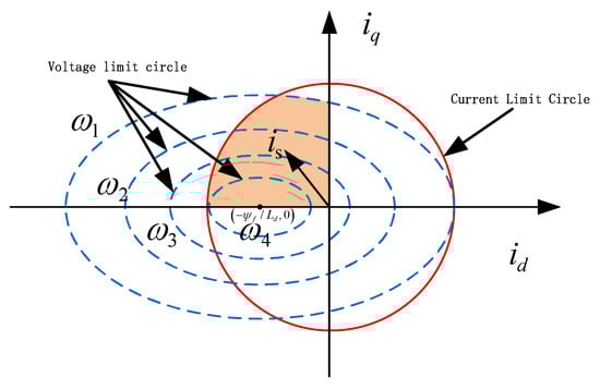
Figure 1.
Voltage Limit Circle and Current Limit Circle.
As shown in Figure 1, when the motor speed exceeds the rated speed by , . If the speed continues to increase at this point, the vector angle γ of the control current can be increased to adjust the magnitudes of and . This angle is referred to as the advance angle. The weak-field control via the advance angle directly modulates the magnitude of the advance angle to alter and , maximizing the output electromagnetic torque and enabling the IPMSM to operate along a predetermined current trajectory. By subtracting the square sum of the direct-axis voltage and the cross-axis voltage and —set by the current regulator—from the inverter terminal voltage limit value of the IPMSM, and defining this difference as K, we obtain
As speed increases beyond the base speed, the back-EMF approaches the inverter’s DC-link voltage limit . To prevent voltage saturation and allow further speed increase, flux weakening is initiated. The control variable defined in Equation (14) has a clear physical interpretation: it represents the squared voltage margin. When , sufficient voltage headroom exists; when , the voltage limit is violated, indicating the need for immediate flux weakening.
Feed the difference K back to the leading angle weak magnetic module to obtain the tuning values and for the direct-axis current and cross-axis current:
The and values obtained from the leading-angle weak-magnetism control are fed back to the MTPA control module. The tuned direct-axis and cross-axis current values are then applied to the MTPA control system of the Field Oriented Control (FOC), completing the MTPA-based leading-angle weak-magnetism control for the IPMSM, as shown in Figure 2.
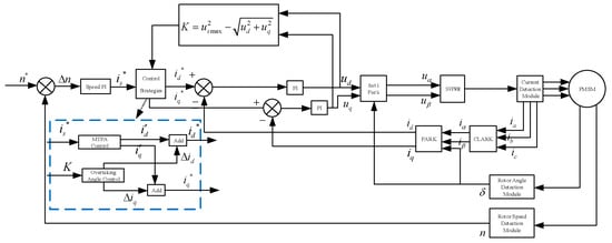
Figure 2.
Block Diagram of the Advance Angle Weak Magnetic Control System Based on MTPA for IPMSM.
3. Smooth Switching Control Strategy for the Weak Magnetic Region in PMSM
3.1. IPMSM Trajectory Segmentation
To more clearly describe the weak magnetic field operating state of the IPMSM, its operating trajectory must be divided into intervals. This trajectory is characterized by the direct-axis current and the cross-axis current, as shown in Figure 3. Building upon the IPMSM’s MTPA-based leading-angle weak magnetic field speed control, a deep weak magnetic field zone is introduced. Based on different speed control strategies, this zone is divided into three regions, with the motor parameter relationships for each region illustrated in Figure 4.
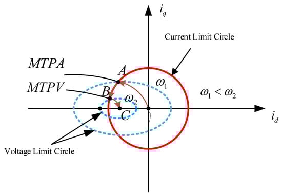
Figure 3.
IPMSM weak magnetic trajectory diagram.
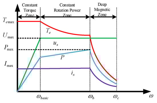
Figure 4.
IPMSM weak magnetic control zone division diagram.
- Zone 1: This phase is defined as the constant torque operation zone. The IPMSM operates below base speed, following the maximum torque-to-current ratio trajectory using MTPA control, as illustrated by curve OA in Figure 3. Constrained only by the current limit circle, the IPMSM delivers maximum torque, with output power increasing proportionally. As the motor approaches base speed, the bus voltage nears its limit value. To continue acceleration, the system must transition to the weak-field phase.
- Zone 2: This phase is defined as the constant-power weak-field zone, also known as the first weak-field stage. The IPMSM operates above base speed using leading-angle weak-field control, with its trajectory shown as curve AB in Figure 3. The motor is constrained by both the current limit circle and the voltage limit circle, resulting in reduced torque (i.e., load-carrying capacity) while output power remains nearly constant. To continue accelerating, the motor must transition into the second weak-field stage.
- Zone 3: To broaden the IPMSM operating speed range, this phase is defined as the deep weak-field zone, also termed the second weak-field stage. The IPMSM achieves higher speeds by sacrificing more torque for rotational speed. The optimal strategy involves operating along the maximum torque-to-voltage ratio (MTPV) trajectory, illustrated by curve BC in Figure 3. Constrained by the voltage limit circle, the motor experiences a sharp torque drop as cross-axis current decreases to achieve higher speeds. Under ideal conditions, point C represents the maximum achievable operating speed. However, in practical scenarios, factors such as iron losses, copper losses, and air friction losses prevent the cross-axis current from reaching zero during normal operation. Consequently, point C is generally unattainable.
As shown in Figure 3, the switching point between Region 1 and Region 2 is point A, the intersection of the MTPA curve and the current limit circle. The switching point between Region 2 and Region 3 is point B, the intersection of the MTPV curve and the current limit circle. To determine their coordinates, we first examine the MTPV curve.
Research into weak-field control of the deep weak-field region in IPMSMs requires a thorough understanding of the maximum torque-voltage ratio curve. From the electromagnetic torque equation and the stator voltage equation during high-speed operation, it follows that for any given electromagnetic torque , an infinite number of combinations can yield it. Furthermore, since the voltage vector is the sum of the squares of and , this implies an infinite number of vectors satisfying the solution. This set is defined as U. Within U, there must exist a minimum that maximizes the value of . In the coordinate system, each corresponds to a unique coordinate point. Connecting the points corresponding to different values and forms the MTPV (Maximum Torque Per Volt) curve.
As shown in Figure 5, the MTPV curve is defined by the tangent line connecting the isotorque curve and the voltage limit circle. When an IPMSM employs MTPV for weak-field control, the output torque reaches its maximum value while the field current remains constant. Therefore, in the deep weak-field region, the IPMSM achieves optimal weak-field speed enhancement by following the MTPV curve as its operating trajectory. Solving the MTPV curve involves determining the extrema of and . According to the optimization principle of Lagrange’s extremum theorem, an auxiliary function is introduced, expressed as
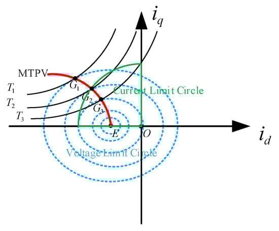
Figure 5.
MTPV curves.
The partial derivatives of Equation (16) can be taken to find its extrema:
When organized, the following is obtained:
Then, the expressions for and are obtained in terms of rotational speed under MTPV:
Among these, .
Expressing and in terms of the polarizability yields
Among these, .
At this moment, the magnitude of the electromagnetic torque of the IPMSM is
Equations (19)–(21) provide the complete analytical description of the MTPV trajectory. The key physical insight revealed by these equations is that on the MTPV curve, the d-axis current becomes increasingly negative (indicating stronger demagnetization) as speed rises, while the q-axis current must decrease concurrently to satisfy the voltage constraint. This dynamic directly causes the characteristic sharp decline in output torque observed in the deep flux-weakening region, which is the fundamental trade-off for achieving maximum speed extension. Thus, the MTPV curve defines the optimal current trajectory that balances torque production against voltage limitation at high speeds.
3.2. IPMSM Weak Magnetic Switching Point Tuning
The transition point between the constant torque region and the constant power region is point A. Point A is the intersection of the current limit circle and the MTPA curve, where the relationship between is
The transition point between the constant-power weak magnetic field region and the deep weak magnetic field region is designated as point B. The relationship between is defined as follows:
By examining Equations (22) and (23), it is evident that the expression for is highly complex. In practical system control, significant errors may occur. Using points A and B as transition points between the three speed control zones to switch control strategies can introduce deviation at the switching points, causing sharp transitions in the IPMSM trajectory and resulting in abrupt transitions between zones. In more severe cases, delay errors at the switching moment at point A may cause the switching point to fall outside the current limit circle, leading to saturation of the voltage and current regulators and system instability. To address the time-varying nature, complexity, and instability of system parameters in IPMSM speed control systems, an adaptive fuzzy controller is introduced. This enhances switching accuracy and stability, enabling smooth transitions between speed control zones.
3.3. Adaptive Fuzzy Algorithm-Based Smooth Transition Strategy for IPMSM Speed Regulation Zones
3.3.1. Research on Fuzzy Control Strategies
The principle of fuzzy control is shown in Figure 6. Firstly, the selected reference value is input into the system for fuzzification, and after reasoning according to the fuzzy rules, the fuzzy set is defuzzified by anti-fuzzification, and the processed parameters are applied to the control object as the output, which is fed back to the system to realize the fuzzy control.
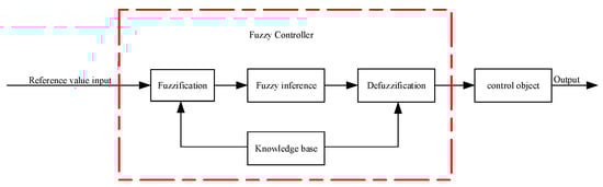
Figure 6.
Fuzzy Control Block Diagram.
The transition of the IPMSM from the constant torque region to the normal weak magnetic region and the transition between the normal weak magnetic region and the deep weak magnetic region are two different transition cases. The design is carried out separately for the above two cases:
- 1.
- Case 1:
Transition from the constant torque zone to the ordinary weak magnetic zone, its most distinctive feature is the increase in rotational speed as well as the bus voltage, so the IPMSM rotational speed , as well as are selected as inputs to the fuzzy controller, and is selected as the output of the fuzzy controller. For the fuzzification of the input values, the following fuzzy rules need to be followed:
When the rotational speed is very small, and the IPMSM is boosted along the MTPA trajectory, should be very large and close to the current vector , is a very small negative value with a minimum of ;
When the rotational speed gradually increases, the MTPA trajectory of IPMSM gradually flattens, gradually decreases, and gradually increases;
As gradually increases to the base speed, it approaches the current limit circle, is small or zero, and gradually increases to zero.
According to the above fuzzy rules, select appropriate modifier words as fuzzy statements for the fuzzy inputs, and divide into five fuzzy sets: {very small (VS), small (S), medium (M), large (L), very large (VL)}, and divide and the output variable into five sets: {positively large (PB), positively small (PS), zero (ZO), negatively small (NS), negatively large (NB)}, and according to the above rules formulate the fuzzy rule table of with respect to and as shown in Table 1:

Table 1.
Fuzzy rule table for Case 1.
This fuzzy rule table takes into account the dual influence of IPMSM speed and voltage vector, which ensures that the motor runs along the MTPA trajectory, and also ensures that voltage saturation is avoided at the switching point, realizing smooth transition in the speed control region and ensuring stable switching of control strategies in different speed control intervals.
- 2.
- Case 2:
Transition from ordinary weak magnetic region to deep weak magnetic region, it is known that the coordinates of and at the intersection point of MTPV and current limit circle are , and since is the negative semiaxis, take the absolute value of the straight-axis current at the current moment, , and the intersection-axis current, , (which is obtained from the collected three-phase currents of IPMSM through the transformation), and its difference are as follows:
Introduce the depth weak magnetization weight factor (), select as the input of the fuzzy controller, and as the output; control the value of through the fuzzy controller to control the moment when the motor enters the depth weak magnetic region. Now the expression of the straight-axis current in the weak magnetic region of the motor is corrected, and the corrected straight-axis current in the commutation controller is
When , , and is large, the IPMSM operates in the normal weak magnetic region, the value of is 0, and overdrive angle weak magnetic control is used;
As slowly decreases, gradually increases when . In order to avoid saturation of the current regulator caused by early switching of the system to MTPV before point B, a certain overshoot of the switching point is allowed, i.e., switching when and ( is a very small number greater than zero), and at this moment is maximum and is 1.
Based on the above analysis, is divided into three sets: {Negative (N), Zero (Z), Positive (P)}, and is divided into five sets: {Negative Big (NB), Negative Small (NS), Zero (ZO), Positive Small (PS), and Positive Big (PB)}, and the output variable is divided into three fuzzy sets: {Low (L), Medium (M), and High (H)}, and the corresponding values of numerical intervals will be generated as the values of fuzzy table about and , as shown in Table 2:
Table 2.
Fuzzy rule table for Case 2.
This fuzzy control rule ensures the smooth switching of the IPMSM from the constant power weak magnetic region to the deep weak magnetic region by analyzing the relationship between and smoothing control of the weight .
The adaptive smooth switching controller is built in the SIMULINK environment. The quadrant switching simulation model between region one and region two is shown in Figure 7. The inputs and outputs of the adaptive fuzzy control are built in the Fuzzy toolbox, and the limit ranges of their values are set, and the membership functions are configured. The input parameters and use the normal distribution function, and the output parameter uses the triangular sawtooth function, as shown in Figure 7a. Configure the logical relationship between the input and output parameters according to the fuzzy rules, as shown in Figure 7b. After the fuzzy rules are set up, the logical relationship between the parameters can be characterized by the 3D plane of Figure 7c and can be dynamically displayed by Figure 7d.
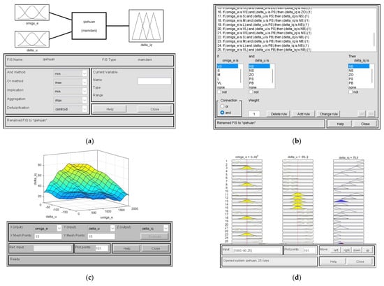
Figure 7.
Simulation model of quadrant switching between region 1 and region 2. (a) Fuzzy Control Block Diagram; (b) Fuzzy Control Block Diagram; (c) Fuzzy Control Block Diagram; (d) Fuzzy Control Block Diagram.
The design of the quadrant switching simulation model between region 2 and region 3 is shown in Figure 8. Its input parameter use a normal distribution function, and the output parameter uses a triangular sawtooth function. It is shown in Figure 8a. The logical relationship between the input and output parameters is configured according to the fuzzy rules, as shown in Figure 8b. After the fuzzy rules are set up, the logical relationship between the parameters can be characterized by the 3D plane of Figure 8c and can be dynamically displayed by Figure 8d.
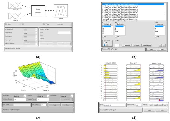
Figure 8.
Simulation model of quadrant switching between region 2 and region 3. (a) Fuzzy Control Block Diagram; (b) Fuzzy Control Block Diagram; (c) Fuzzy Control Block Diagram; (d) Fuzzy Control Block Diagram.
3.3.2. Research on Adaptive Control Strategies
An adaptive strategy is introduced into the fuzzy controller to compensate for the uncertainty of the parameters online to ensure that the fuzzy controller is sensitive to the changes in the speed and current of the IPMSM, which makes the switching strategy smoother and robust and prevents the system from going out of control. The dynamic equations of the IPMSM in the d-q axis are
where is the mechanical rotational speed, the electrical angular velocity , and are the moment of inertia, friction coefficient, and load torque, respectively.
The error variable is defined:
where are the rotational speed error, direct axis current error, and cross-axis current error, respectively, and are the reference rotational speed and the reference direct axis and cross-axis currents, respectively.
The parameter estimation error is defined:
where are the given parameters of constant resistance, direct-axis inductance, cross-axis inductance, and permanent magnet chain, respectively, and are the estimated values of constant resistance, direct-axis inductance, cross-axis inductance, and permanent magnet chain, respectively.
The Lyapunov function is designed based on the inclusion of state error and parameter estimation error:
where are the adaptive gains and are all greater than zero.
The derivation of and substitution into the system equation gives
Then the output voltage of the controller is
where , is the control gain.
To stabilize the system, it is necessary to ensure that , the design parameter adaptation rate:
Substituting the above equation into , we get
According to Lyapunov stability theory, the first-order derivative of voltage is not greater than zero, and the system is globally asymptotically stable.
In summary, an adaptive strategy is introduced on the basis of the fuzzy controller to compensate the fuzzy parameters online, and the fuzzy controller inputs the compensated output value when switching from the constant torque zone to the normal weak magnetic zone, and inputs the depth weak magnetic coefficients weight when switching from the normal weak magnetic zone to the depth weak magnetic zone to complete the research on the design of the adaptive fuzzy controller.
3.3.3. Discussion on Computational Complexity and Real-Time Feasibility for EV Drives
The practical deployment of the proposed adaptive fuzzy control strategy in electric vehicle (EV) drives requires a clear assessment of its computational load and real-time feasibility.
The algorithm primarily consists of three computational components: fuzzy inference, Lyapunov-based adaptive law updates, and standard current/trajectory calculations for MTPA, leading-angle, and MTPV operations. Fuzzy inference—comprising fuzzification, rule evaluation (using 25 rules for Case 1 and 15 for Case 2), and center-of-gravity defuzzification—involves only linear-complexity operations. The parameter adaptation law, executed at the same frequency as the current control law, requires several multiplications and additions per cycle. Although the inclusion of fuzzy logic and online adaptation increases processing demands compared to a basic PI-based controller, the total computational burden remains well within the capabilities of modern automotive-grade microcontrollers or digital signal processors. Such hardware commonly integrates floating-point units, trigonometric accelerators, and ample memory, enabling the execution of far more complex algorithms within tight inverter switching periods. Moreover, the fuzzy and adaptive modules can be scheduled at a moderately lower rate than the current regulator without significantly compromising performance.
Consequently, the proposed strategy is fully real-time feasible for EV traction applications. The modest increase in computational cost is justified by the substantial improvement in transition smoothness and operational stability across the entire speed range, which directly enhances drivability and overall vehicle dynamics.
4. Simulation
In this chapter, the operation characteristics of IPMSM in different speed domains are analyzed in detail through the MATLAB(R2023b)/SIMULINK simulation platform, and the performance of the system is compared between the traditional control strategy and the system performance after the introduction of the adaptive fuzzy control strategy. The IPMSM full-speed domain weak magnetic control system is constructed in the simulation environment of MATLAB/SIMULINK, and the IPMSM parameters used in the simulation model are shown in Table 3.
Table 3.
IPMSM parameter.
4.1. Analysis of Simulation Results
4.1.1. Constant Torque Zone
Within the constant torque region, the IPMSM operates below the base speed, and the MTPA control strategy is used. The simulation waveforms compare the system response before and after the introduction of fuzzy control, as shown in Figure 9. Figure 9a shows the simulated waveforms of speed, torque, and of the system before the introduction of fuzzy control; Figure 9b shows the simulated waveforms of speed, torque, and of the system after the introduction of fuzzy control.
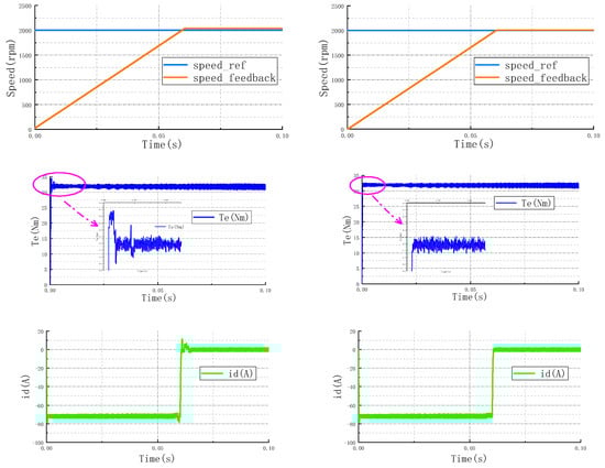
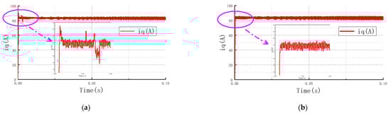
Figure 9.
System response in the constant torque region. (a) Before fuzzy speed, torque, , ; (b) After fuzzy speed, torque, , .
In the constant torque region, the system operates under MTPA control. The comparative waveforms in Figure 9 demonstrate the effect of introducing the proposed fuzzy controller. The conventional method results in a speed response with noticeable overshoot and oscillation during startup. In contrast, the proposed strategy yields a markedly smoother speed transition with virtually no overshoot. This improvement is mirrored in the torque response, where the initial impact and subsequent fluctuations are significantly suppressed. Furthermore, the d- and q-axis currents under the proposed control exhibit a more stable and smoother trajectory.
4.1.2. Constant Power Zone
In the constant power weak magnetization region, the IPMSM is operated above the base speed, and the overstepping angle weak magnetization control strategy is adopted. The simulated waveforms compare the system response before and after the introduction of fuzzy control, as shown in Figure 10. Where Figure 10a shows the simulated waveforms of speed, torque, and of the system before the introduction of fuzzy control; Figure 10b shows the simulated waveforms of speed, torque, and of the system after the introduction of fuzzy control.
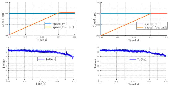
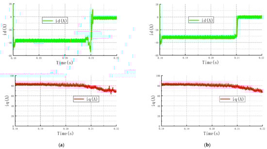
Figure 10.
System response in the constant power region. (a) Before fuzzy speed, torque, , ; (b) After fuzzy speed, torque, , .
The performance in the constant power region is evaluated in Figure 10. The key challenge here is the transition at the switching point. With the conventional leading-angle control, the speed shows obvious jitter near this point, accompanied by a pronounced torque dip and abrupt changes in both and currents. The proposed adaptive fuzzy strategy effectively addresses these issues. It facilitates a smooth speed transition without noticeable shock, reduces the torque dip magnitude, and ensures a continuous evolution of the d-axis and q-axis currents.
4.1.3. Deep Weak Magnetic Zone
In the constant power weak magnetization region, the IPMSM is operated above the base speed, and the overstepping angle weak magnetization control strategy is adopted. The simulated waveforms compare the system response before and after the introduction of fuzzy control, as shown in Figure 11. Where Figure 11a shows the simulated waveforms of speed, torque, and of the system before the introduction of fuzzy control; Figure 11b shows the simulated waveforms of speed, torque, and of the system after the introduction of fuzzy control.
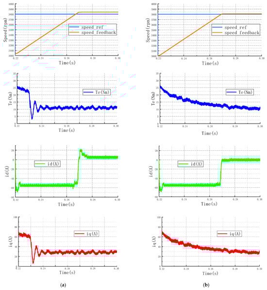
Figure 11.
System response in the deep flux-weakening region. (a) Before fuzzy speed, torque,
, ; (b) after fuzzy speed, torque, , .
Figure 11 presents the system behavior in the deep flux-weakening region, where the transition to MTPV-like operation is critical. Similar to the constant power zone, the conventional method suffers from speed jitter, a sharp torque drop, and drastic current changes at the switching point. The proposed method proves effective in smoothing these transitions. The speed response is stable, the torque dip is minimized, and the d-axis and q-axis currents vary continuously. The proposed controller manages to stabilize the operation deep into the flux-weakening region, thereby validating its robustness and the effectiveness of the integrated adaptive mechanism.
4.2. Discussion
The MTPA constant-power leading-angle current trajectory in the d-q coordinate system is shown in Figure 12. Under the MTPA weak-field strategy, the IPMSM accelerates from point O to point A. At point A, the adaptive fuzzy controller performs a smooth transition into leading-angle weak-field control. The AB segment represents the constant-power weak-field zone under leading-angle weak-field control. The transition point exhibits a relatively smooth trajectory waveform, demonstrating excellent switching performance.
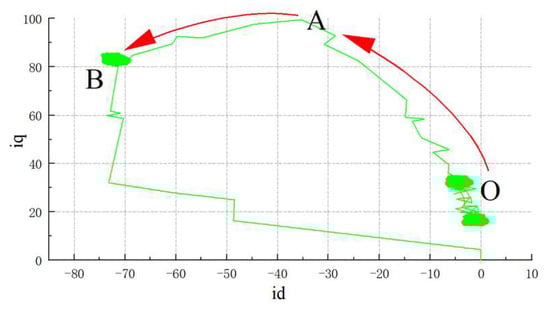
Figure 12.
MTPA with Constant-Power Current Trajectory.
The smooth transition trajectory from the ordinary weak magnetic zone to the deep weak magnetic zone is shown in Figure 13. Starting from point B, the weight for the deep weak magnetic field region gradually increases. Upon reaching point C, the IPMSM exits the leading-angle weak magnetic field and enters the deep weak magnetic field region. The segment CD represents the MTPV trajectory. Due to the complexity of the MTPV formula calculations, the transition to the deep weak magnetic field region results in a shallow weak magnetic field depth. This necessitates further research into control strategies for the deep weak magnetic field region.
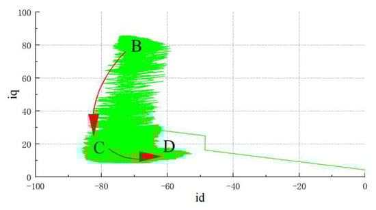
Figure 13.
MTPV with Constant-Power Current Trajectory.
A comparative analysis is provided here to position the proposed adaptive fuzzy transition strategy against two established advanced control methods mentioned in the literature: Model Predictive Control (MPC) and Sliding-Mode Control (SMC), in the context of flux-weakening operation. MPC utilizes a system model to predict future behavior and optimizes control inputs over a receding horizon, offering high dynamic performance and inherent constraint handling. However, its computational burden increases significantly with prediction horizon and system complexity, requiring powerful processors, especially when parameter variations are considered. SMC offers strong robustness against disturbances and parameter uncertainties due to its discontinuous control law, driving the system onto a predefined sliding surface. Yet, its practical application often suffers from chattering, which may excite high-frequency dynamics and increase losses.
In contrast, the proposed method emphasizes rule-based smooth transition management rather than global torque or current re-optimization. Its novelty lies in the dedicated fuzzy logic design for each switching zone, coupled with a Lyapunov-based online parameter adaptation mechanism. This structure allows it to handle the nonlinear and parameter-sensitive nature of transition transients without requiring a precise mathematical model of the entire operating envelope. While not as computationally optimal as MPC in a strict sense, it offers a favorable trade-off: it significantly reduces switching oscillations compared to conventional methods, maintains lower computational complexity than MPC for high-frequency drive cycles, and avoids the inherent chattering of SMC. Thus, the strategy is particularly suited for IPMSM traction drives where smoothness, real-time feasibility, and robustness to parameter changes are critical.
5. Conclusions
This paper investigates a smooth transition control strategy for interior permanent magnet synchronous motors (IPMSMs) in wide-speed-range applications, such as electric vehicle traction drives. The primary contribution is a novel adaptive fuzzy control strategy, developed within a composite MTPA-leading-angle flux-weakening framework, to eliminate oscillations and instability during mode switching. After analyzing the deep flux-weakening conditions and the MTPV-based trajectory, the motor’s full-speed operation is divided into distinct zones. Dedicated fuzzy controllers, enhanced by a Lyapunov-based online parameter adaptation mechanism, are designed to ensure smooth transitions between these zones. Simulation results in MATLAB/Simulink validate that the proposed strategy achieves seamless switching across the entire speed range. The validated smooth transition strategy not only improves the operational reliability of IPMSMs but also provides a viable control solution for advanced traction systems, contributing to better dynamic performance and energy efficiency in electric vehicles.
While the current study is based on simulation, which represents a limitation, it provides a solid conceptual and parametric foundation. The strategy offers a viable high-performance control solution for EV traction systems, contributing to enhanced drivability and energy efficiency. Future work will focus on experimental validation using a motor drive testbench to evaluate performance under real-world conditions.
Author Contributions
Conceptualization, X.Y. and W.Z.; methodology, X.Y. and W.Z.; validation, X.Y. and P.Z.; writing—original draft preparation, X.Y.; writing—review and editing, W.Z. and P.Z.; supervision, W.Z. and P.Z. All authors have read and agreed to the published version of the manuscript.
Funding
This research was funded by Natural Science Foundation of Jiangsu Province, grant number No. BK20231257.
Data Availability Statement
The original contributions presented in this study are included in the article. Further inquiries can be directed to the corresponding author.
Conflicts of Interest
The authors declare no conflicts of interest.
References
- Çavuş, B.; Aktaş, M. MPC-Based Flux Weakening Control for Induction Motor Drive with DTC for Electric Vehicles. IEEE Trans. Power Electron. 2023, 38, 4430–4439. [Google Scholar] [CrossRef]
- Chang, C.-C.; Chen, Z.-J.; Cheng, C.-A.; Chiu, H.-N.; Chen, Y.-M. Information Acquisition of Pulsating Voltage for Electric Motor Emulator Applications. IEEE Trans. Power Electron. 2023, 38, 15921–15931. [Google Scholar] [CrossRef]
- El Khatib, H.; Peña, M.; Grothmann, B.; Gedlu, E.; Saur, M. Flux Observer-Based MTPF/MTPV-Operation with Low Parameter Sensitivity Applying Deadbeat-Direct Torque and Flux Control. IEEE Trans. Ind. Appl. 2021, 57, 2494–2504. [Google Scholar] [CrossRef]
- Atashin, S.A.; Zarchi, H.A.; Markadeh, G.A. Online Adaptive Current Vector Adjustment for Deep Flux-Weakening Control of IPMSM. IEEE Trans. Power Electron. 2023, 38, 2339–2350. [Google Scholar] [CrossRef]
- Ni, Y.; Zhang, L.; Qiu, Z. Investigation of surface-inset machines with mixed grade magnets considering magnet thickness. CES Trans. Elect. Mach. Syst. 2022, 6, 252–260. [Google Scholar] [CrossRef]
- Li, H.; Qian, Y.; Asgarpoor, S.; Sharif, H. Simulation Study on On-Line MTPA/MTPV Trajectory Tracking in PMSMs with Power Management. Electr. Power Compon. Syst. 2020, 48, 241–255. [Google Scholar] [CrossRef]
- Xia, Z.; Nalakath, S.; Tarvirdilu-Asl, R.; Sun, Y.; Wiseman, J.; Emadi, A. Online Optimal Tracking Method for Interior Permanent Magnet Machines With Improved MTPA and MTPV in Whole Speed and Torque Ranges. IEEE Trans. Power Electron. 2020, 35, 9753–9769. [Google Scholar] [CrossRef]
- Huang, M.; Lin, H.; Yunkai, H.; Jin, P.; Guo, Y. Fuzzy Control for Flux Weakening of Hybrid Exciting Synchronous Motor Based on Particle Swarm Optimization Algorithm. IEEE Trans. Magn. 2012, 48, 2989–2992. [Google Scholar] [CrossRef]
- Qin, C.; Li, X.; Xing, X.; Zhang, C.; Zhang, G. Common-mode voltage reduction method for three-level inverter with unbalanced neutral-point voltage conditions. IEEE Trans. Ind. Informat. 2021, 17, 6603–6613. [Google Scholar] [CrossRef]
- Wang, C.; Zhu, Z.Q. Fuzzy Logic Speed Control of Permanent Magnet Synchronous Machine and Feedback Voltage Ripple Reduction in Flux-Weakening Operation Region. IEEE Trans. Ind. Appl. 2020, 56, 1505–1517. [Google Scholar] [CrossRef]
- Deng, W.; Zhang, Q.; Yan, B.; Li, S. Direct Torque Control of PMSM Drives for Common-Mode Voltage Reduction and Steady-State Performance Improvement. IEEE Trans. Transp. Electrif. 2025, 11, 1629–1639. [Google Scholar] [CrossRef]
- Wang, Y.; Zhang, Y.; Yang, H.; Rodriguez, J. Variable-Vector-Based Model Predictive Control With Reduced Current Harmonic and Controllable Switching Frequency for PMSM Drives. IEEE Trans. Power Electron. 2024, 39, 16429–16441. [Google Scholar] [CrossRef]
- Çavuş, B.; Aktaş, M. A New Adaptive Terminal Sliding Mode Speed Control in Flux Weakening Region for DTC Controlled Induction Motor Drive. IEEE Trans. Power Electron. 2024, 39, 449–458. [Google Scholar] [CrossRef]
- Chen, S.-G.; Lin, F.-J.; Liang, C.-H.; Liao, C.-H. Development of FW and MTPV Control for SynRM via Feedforward Voltage Angle Control. IEEE/ASME Trans. Mechatron. 2021, 26, 3254–3264. [Google Scholar] [CrossRef]
- Yao, K.; Du, B.; Li, J.; Huang, W.; Cheng, Y.; Zhang, Q.; Cui, S. Torque Closed-Loop Flux-Weakening Control of IPMSM Based on Search Coils. IEEE Trans. Ind. Electron. 2025, 72, 122–133. [Google Scholar] [CrossRef]
- Wang, X.; Wang, Q.; Yang, Z.; Li, Y. Sensorless Control of Permanent Magnet Synchronous Motorized Spindles With Parameters Adjustment Based on Fuzzy Control Algorithm. IEEE J. Emerg. Sel. Top. Power Electron. 2025, 13, 5262–5272. [Google Scholar] [CrossRef]
- Chen, Y.Z.; Fang, Y.T.; Huang, X.Y.; Zhang, J. Torque and Flux Weakening Control with MTPV for Interior Permanent Magnet Synchronous Motor. In Proceedings of the 2016 IEEE Vehicle Power and Propulsion Conference (VPPC), Hangzhou, China, 17–20 October 2016; pp. 1–5. [Google Scholar]
- Himker, N.; Lindemann, G.; Wiedmann, K.; Weber, B.; Mertens, A. A Family of Adaptive Position Estimators for PMSM Using the Gradient Descent Method. IEEE J. Emerg. Sel. Top. Power Electron. 2022, 10, 1946–1962. [Google Scholar] [CrossRef]
- Zhu, L.; Xue, S.; Wen, X.; Li, Y.; Kong, L. A new deep field-weakening strategy of IPMSM machines based on single current regulator and voltage angle control. In Proceedings of the Energy Conversion Congress and Exposition (ECCE), Atlanta, GA, USA, 12–16 September 2010; pp. 1144–1149. [Google Scholar]
- Lee, H.J.; Shon, J.G. Improved voltage flux-weakening strategy of permanent magnet synchronous motor in high-speed operation. Energies 2021, 14, 7464. [Google Scholar] [CrossRef]
- Canseven, H.T.; Petrov, I.; Pyrhönen, J. Impact of Stator Core Magnetic Asymmetry on the Properties of a High Specific Power PMSM. IEEE Trans. Ind. Appl. 2024, 60, 3830–3839. [Google Scholar] [CrossRef]
- Kadupu, S.C.; Vaishnav, K.; Pandey, N.; Kant, P. Modified MTPA Controlled Interior Permanent Magnet Synchronous Motor Drive for Electric Vehicle Application Considering Magnetic Saturation. In Proceedings of the 2024 IEEE International Conference on Power Electronics, Drives and Energy Systems (PEDES), Mangalore, India, 18–21 December 2024; pp. 1–6. [Google Scholar]
- Yu, W.; Qi, J.; Hua, W.; Zhou, J. Investigation of Interior Permanent Magnet Machine With Integrated High and Low Voltage Windings for Electronic Hydraulic Power Steering. IEEE Trans. Transp. Electrif. 2025, 11, 10378–10390. [Google Scholar] [CrossRef]
- Wang, F.; Kong, W.; Wang, Z. Dynamic Flux Weakening-Based DPCC for Rapid Torque Rise of SPMSM Drives at Medium-to-High Speeds. IEEE Trans. Ind. Electron. 2025, 72, 11035–11047. [Google Scholar] [CrossRef]
- Lu, C.; Cheng, J.; Xu, X.; Wang, X. A fuzzy coefficient deep flux weakening algorithm for IPMSM without out-of-control. ISA Trans. 2024, 153, 443–452. [Google Scholar] [CrossRef]
Disclaimer/Publisher’s Note: The statements, opinions and data contained in all publications are solely those of the individual author(s) and contributor(s) and not of MDPI and/or the editor(s). MDPI and/or the editor(s) disclaim responsibility for any injury to people or property resulting from any ideas, methods, instructions or products referred to in the content. |
© 2026 by the authors. Published by MDPI on behalf of the World Electric Vehicle Association. Licensee MDPI, Basel, Switzerland. This article is an open access article distributed under the terms and conditions of the Creative Commons Attribution (CC BY) license.