Abstract
In multi-load wireless power transfer (WPT) systems, when multiple loads simultaneously charge using the same transmitter, the unpredictable spatial positions of the loads and the presence of cross-coupling make it challenging to achieve complete system decoupling, thereby limiting the effective power reception area. To address this issue, this paper investigates a one-to-multiple WPT system based on a single-transistor P#-type LCC-S compensation network. Air-core coils are employed at the receiving end to mitigate cross-coupling, and the effective power reception area is analyzed. First, the operating principle of the system is examined and the parameter configuration conditions for the resonant circuit are derived. Then, MATLAB/Simulink R2022b is used to establish simulation circuit models for both single-transmitter single-receiver and single-transmitter dual-receiver WPT systems. The results indicate that for an effective output power of 5 W, the mutual inductance ranges are (3.5, 6) μH and (3, 6.5) μH, respectively. Next, finite element simulations are conducted to analyze the mutual inductance variations caused by spatial misalignment of the coils. For the single-transmitter single-receiver system, when the transmission distance is 5–12.5 mm, the effective power reception area corresponds to an X- and Y-axis misalignment of ±15 mm, while at a transmission distance of 10 mm, the effective reception area is ±10 mm along both axes. In the single-transmitter dual-receiver system, for a transmission distance of 5–14 mm, the maximum reception area is ±15 mm along the X-axis and ±10 mm along the Y-axis. Finally, an experimental platform is built to verify that multiple loads at different positions can achieve effective power reception for charging.
1. Introduction
With the global development of the energy internet and increasing electrification, Wireless Power Transfer (WPT) technology has garnered significant attention due to its potential for power transmission without physical connections [1,2]. WPT offers numerous advantages, including high reliability, strong safety, and convenience, making it applicable in diverse fields such as electric vehicles, consumer electronics, and underwater unmanned devices [3,4,5].
Nowadays, users seek to charge multiple devices simultaneously, driving the development of multi-receiver coil WPT technology [6]. However, this technology faces challenges such as cross-coupling, uneven power distribution, and misalignments of receiver coils. For instance, in wireless drone charging applications, environmental factors make it difficult to ensure the precise landing accuracy of the charging coil, potentially causing deviations from the optimal charging position and reducing charging efficiency [7,8]. In emergency scenarios in which multiple drones need to be charged simultaneously, limited charging positions may further hinder timely task responses [9].
In multi-receiver WPT systems, the spatial distribution of receiver coils is unpredictable, and precise alignment with the transmitter coil is often difficult to achieve, leading to variations in mutual inductance that affect power transfer efficiency [10]. Additionally, cross-coupling effects among receiver coils may result in uneven power distribution, in which case some receivers fail to obtain sufficient energy while others experience over-coupling, altering the system’s resonance characteristics and degrading its overall transmission performance [11]. Therefore, studying the effective power reception area of multi-receiver WPT systems is crucial [12]. Analyzing this area helps determine the spatial range in which receiver coils can still obtain adequate power, providing theoretical support for system design and improving the system’s tolerance of positional errors [13]. Optimizing the effective power reception area not only reduces strict alignment requirements for charging positions but also enhances the stability and robustness of wireless charging, making it more suitable for practical applications such as wireless drone charging and automated guided vehicle (AGV) charging [14].
Existing studies indicate that the output power and transmission efficiency of multi-load WPT systems are predominantly determined by the coupling coefficient. Variations in the coupling coefficient significantly impact system performance, especially when magnetic coupling mechanisms experience misalignment or rotation, leading to a considerable drop in transmission efficiency [15,16,17]. To mitigate these effects, impedance compensation circuits or control algorithms based on primary and secondary parameter detection are often employed, though they tend to increase system complexity and cost [18,19]. Reference [20] proposed a dual-coil WPT system with constant voltage characteristics, emphasizing that the system’s stability relies on changes in the equivalent coupling coefficient. To address misalignments, designs incorporating coils of varying sizes and larger transmitter coils have been proposed to extend the magnetic field’s range, ensuring the receiver coil remains within the effective range of the transmitter coil even when misaligned [21,22].
Most multi-receiver coil WPT systems currently use full-bridge or half-bridge topologies, which suffer from issues such as bridge arm shoot-through. In contrast, single-switch resonant inverter circuits have attracted significant interest in WPT systems due to their simple control, low cost, and high reliability. The P#-type single-switch inverter circuit enhances input current waveforms and prevents sudden drops to zero, thereby improving DC (direct current) power supply lifespan and transmission efficiency [23]. P-type compensation topologies (e.g., P-P (parallel-parallel) compensation, P-S (parallel-series) compensation) are commonly used in WPT systems to provide reactive compensation for resonant operation. However, the low voltage gain and quality factor of these topologies limit system performance. Alternatively, LCC-type compensation topologies, with resonant frequencies determined solely by the coil’s self-inductance, offer advantages by decoupling the transmitter coil excitation current from mutual inductance and the load and providing constant voltage output at the receiver side. The LCC-S topology effectively addresses these challenges by ensuring constant current excitation on the transmitter side and constant voltage output on the receiver side, making it a promising solution [24].
Despite these advancements, a critical challenge remains in multi-receiver coil WPT systems. The effective power reception area is significantly influenced by spatial uncertainty and cross-coupling effects, leading to variations in mutual inductance and uneven power distribution. The existing research primarily focuses on improving compensation topologies and control strategies, yet limited studies have systematically analyzed the effective reception area and its impact on system performance. Without a clear understanding of this region, the system’s robustness to receiver coil misalignment remains inadequate, restricting practical applications such as wireless drone and AGV charging.
To address this research gap, this paper investigates the effective reception area of a single-switch P#-type LCC-S compensated WPT system with one transmitter and multiple receivers. The study aims to:
- Analyze the characteristics of the P#-type LCC-S compensation network, emphasizing its ability to decouple the transmitter coil excitation current from mutual inductance and load as well as to maintain a stable output voltage;
- Develop a MATLAB/Simulink model to examine the relationship between system output power and mutual inductance and to identify the mutual inductance range for effective power transfer;
- Conduct finite element simulations to evaluate the impact of receiver coil spatial misalignment on mutual inductance and define the effective power reception area;
- Validate the theoretical and simulation findings through experimental testing, demonstrating that multiple-receiver coils can achieve effective power transfer even under spatial misalignment.
By systematically analyzing the effective power reception area, this study provides theoretical insights and design guidelines to improve spatial tolerance in multi-receiver WPT systems, enhancing their feasibility for practical applications.
The remainder of this paper is organized as follows. Section 2 analyzes the circuit structure of the WPT system and provides the circuit configuration conditions. Section 3 investigates the effective power reception area and determines the range of mutual inductance variations in the WPT system. Section 4 presents experimental validations to verify the effectiveness and feasibility of the proposed system. Finally, Section 5 concludes the paper.
2. Analysis of System Circuit Structure
2.1. Circuit Topology of Single-Switch Inverter WPT System
The circuit structure of a single-transmitter dual-receiver WPT system based on the P#-type LCC-S compensation network is shown in Figure 1. In this system, VDC is the input DC voltage of the single-switch resonant inverter, Q is the power MOSFET, LF is the compensation inductor at the transmitter side, CF is the parallel compensation capacitor at the transmitter side, LT is the transmitter coil inductance, CT is the series compensation capacitor at the transmitter side, LF, CF, CT, and LT constitute the LCC compensation circuit at the transmitter side, RT is the internal resistance of the transmitter coil, LX is the resonant inductor, CX is the resonant capacitor, M is the mutual inductance between the coils, LRn (n = 1, 2) is the inductance of the receiver coils, RRn (n = 1, 2) is the internal resistance of the receiver coils, CRn (n = 1, 2) is the compensation capacitor of the receiver coils, CL is the output filter capacitor, and RL is the load resistance. Each rectifier is followed by a cascaded DC-DC converter to stabilize the output voltage and maintain stable output power.
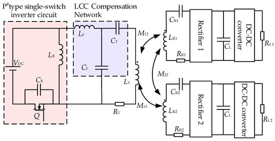
Figure 1.
Single-transmitter dual-receiver WPT system based on P#-type LCC-S compensation network.
2.2. Analysis of the Equivalent Model of the Single-Switch P#LCC-S Compensation Network
As shown in Figure 2, the P#-type single-switch resonant inverter LCC compensation network consists of an LC resonant network and an LCC compensation network. In the circuit analysis, all components are assumed to be ideal to simplify the theoretical derivation, meaning that parasitic resistances, non-ideal switching effects, and component tolerances are neglected.
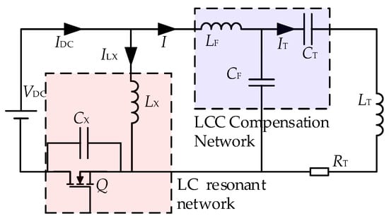
Figure 2.
P# type single-switch resonant inverter LCC compensation network.
For a single-switch inverter circuit, soft-switching needs to be achieved. Based on the load conditions and switching frequency, the parameters of the resonant inductor LX and resonant capacitor CX can be determined to maintain good soft-switching characteristics. The switching frequency of the circuit is f. According to empirical data, the input resonant frequency fin between the resonant inductor LX and resonant capacitor CX is 1.3 to 1.5 times the switching frequency f.
As mentioned in the literature [25], the resonant inductor LX, resonant capacitor CX, and output impedance R have the following relationship:
where k is generally taken as 0.2 to 1.5, and here x is taken as 0.7, so the resonant capacitance Ca is chosen as
The resonant inductor LX is selected as
From the literature [16], the single-switch resonant inverter outputs an AC voltage that can be equated with an AC voltage source Vp. The equivalent circuit of the single coil compensation network is shown in Figure 3, where M is the mutual inductance between the transmitting and receiving coils.
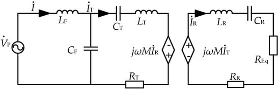
Figure 3.
Equivalent circuit of single coil compensation network.
Write the KVL equation for this circuit [17], where REq = 8RL/π2,
Since the input impedance of the LCC compensation network is purely resistive at resonance, the relationship between the resonant capacitor and inductor can be expressed as follows [26]
Equation (5) defines the resonance conditions for the circuit by setting the products of inductance and capacitance for each resonant tank equal to the reciprocal of the square of the angular frequency ω. Specifically, LF and CF represent the inductance and capacitance of the primary compensation network, (LT − LF) and CT correspond to the compensating components on the transmitter side, and LR and CR denote the inductance and capacitance on the receiver side. These resonance conditions ensure a synchronized resonance between the transmitter and receiver, maximizing power transfer efficiency while minimizing reactive power and stabilizing the output voltage.
By combining Equations (4) and (5), the expression for the branch currents can be expressed as
Then, the output power of the receiving coil can be expressed as
Therefore, when the input rated voltage as well as the load is certain, the system’s output power is only related to the mutual inductance.
The compensation network was analyzed using an AC equivalent model. The equivalent circuit is shown in Figure 4.
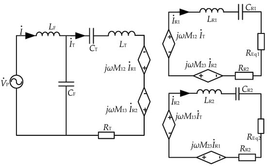
Figure 4.
Equivalent circuit of two receiving coils. Where REq1 = REq2 = 8RL/π2, RL1 = RL2 = RL.
When the LCC compensation network resonates, the input impedance is purely resistive, i.e., the imaginary part is zero, and at this time the following relationship exists for the resonant capacitor inductance
Equation (8) extends the resonance conditions described in Equation (5) to accommodate multiple receivers (i = 1, 2). The inductance LRi and capacitance CRi of each receiver meet the same resonance condition, ensuring that all receivers operate at the same resonant frequency ω. This synchronization not only enhances the overall power transfer efficiency and voltage stability across multiple receivers but also reduces potential interference among receivers, maintaining the stability and reliability of the system.
Neglecting the internal resistance of the coil in the calculation, we obtain
Then the output power is as follows:
3. Analysis of the Effective Power Receiving Area
3.1. Mutual Inductance Range Analysis for Effective Power Reception
In order to obtain the mutual inductance range of the effective power received by the WPT system, the simulation circuit of the single-transmitter-single-receiver/dual-receiver WPT system with P# type LCC-S compensation network is built in Simulink according to the parameters in Table 1, as shown in Figure 5. In order to make the system output a stable effective power, a buck circuit is added to the circuit to stabilize the output voltage at 5 V.

Table 1.
WPT system parameters description.
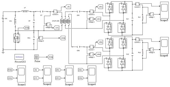
Figure 5.
Simulation circuit of single-transmitter dual-receiver WPT system.
In the MATLAB/Simulink R2022b environment, a WPT system simulation model is constructed as follows:
Step 1: Power Source and Passive Component Configuration. Select a DC voltage source and passive components (resistors, inductors, and capacitors) from the Simscape library. These components are configured based on the WPT system parameters designed in the previous section, as listed in Table 1, to ensure the proper matching of the resonant circuit.
Step 2: Power GUI Module Configuration. In the simulation environment, the Power GUI module is set to “Continuous” mode to enable continuous-time simulation. This setting facilitates accurate capturing of the electromagnetic coupling characteristics and dynamic responses of the WPT system, particularly for high-frequency resonant circuits, allowing the precise transient analysis of current and voltage waveforms.
Step 3: PWM Control Signal Configuration. A pulse module is used to generate PWM signals to control the periodic switching of the MOSFET. The internal parameters of this module are set with an amplitude of 1, a duty cycle of 50%, and an initial phase of 0, ensuring stable operation of the switching devices.
Step 4: Magnetic Coupling Mechanism Configuration. The magnetic coupling mechanism in the system consists of a transmitting coil and two receiving coils, modeled using the mutual inductance model LT: LR1: LR2. This model includes internal parameters such as self-inductance, mutual inductance matrix, and internal resistance matrix, with their matrix expressions given in Equation (11).
Step 5: MOSFET Module Configuration. The simulation employs an N-channel MOSFET as the switching device. Its internal parameters are configured as follows: an on-state resistance of 0.1 Ω, a body diode internal inductance of 0, a body diode internal resistance of 0.1 Ω, a diode forward voltage of 1 V, and a snubber resistance of 100 kΩ.
Step 6: Rectifier Diode Configuration. A full-bridge rectifier circuit is implemented using diodes. The internal parameters of the diode model include an on-state resistance of 0.1 Ω, an on-state inductance of 0, and a forward voltage drop of 0.8 V.
Step 7: Voltage and Current Measurement with Waveform Analysis. Voltage and current measurement modules are used to monitor the operating status at key nodes of the system. A scope oscilloscope is utilized for waveform observation, with specific monitoring assignments as follows: Scope1 monitors the PWM signal and the drain-source voltage VGS, Scope2 monitors the transmitter coil voltage VT and current IT, Scope3 monitors the rectifier input voltage VR1 and current IR1 at Receiver 1, Scope4 monitors the rectifier input voltage VR2 and current IR2 at Receiver 2, Scope5 monitors the output voltage VO1 and current IO1 at Receiver 1, and Scope6 monitors the output voltage VO2 and current IO2 at Receiver 2. Finally, by analyzing the measured waveforms, the operational characteristics of the WPT system are evaluated, and the effectiveness of the proposed design is verified.
Figure 6 shows the voltage waveforms across the switching tubes. It proves that a wide soft-switching margin can be realized in this system with a P# type single tube inverter.
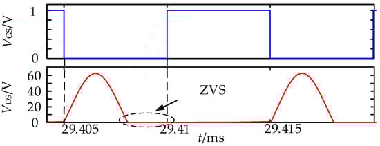
Figure 6.
Soft-switching waveforms.
Figure 7 shows the current-voltage waveforms at the transmitter and receiver ends. From the figure, it can be seen that the voltage and current at the transmitting end are sinusoidal and have a phase difference of 90°, and the current and voltage at the transmitting end are in the same phase, and the system circuit has a good resonant state, which verifies the correctness of the circuit parameter design.
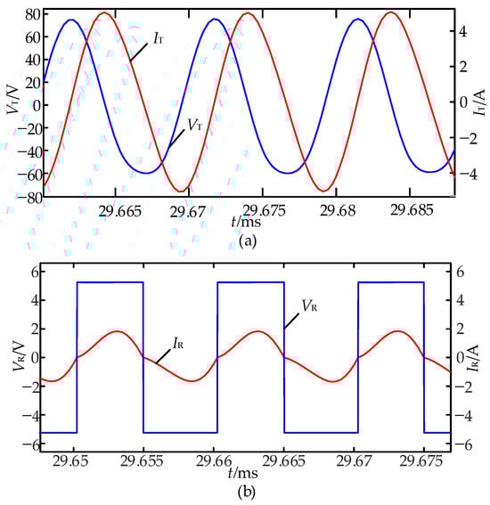
Figure 7.
Simulation model working waveform. (a) Transmitter current and voltage waveforms. (b) Receiver current and voltage waveforms.
The minimum effective power of the system is set to 5 W, considering the practical power requirements of typical low-power wireless charging applications, such as UAVs and AGVs. This threshold aligns with industry standards, such as the Qi wireless charging standard, which specifies a minimum power delivery level to ensure stable and reliable operation of low-power devices. When the receiving coil is misaligned, the mutual inductance between the transmitting and receiving coils changes, leading to variations in the received power. If severe misalignment occurs, the received power may fall below the 5 W threshold, which could compromise the functionality of the load. By setting this threshold, the system ensures that power transmission remains within an acceptable range even under moderate misalignment conditions, enhancing the reliability of multi-receiver WPT applications.
The output power from simulations with different values of mutual inductance is shown in Figure 8. Figure 8a shows the output power of the system with different mutual inductances when the receiving coil is misaligned in a one-to-one system. Figure 8b shows the output power of the system under different mutual inductances in a one to two system, where M13 is the mutual inductance between the transmitting coil and the receiving coil 2, P2 denotes the power of the load on the receiving coil 2, and P1 denotes the power of the load on the receiving coil 1.
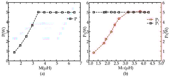
Figure 8.
Output power of the simulation with different values of mutual inductance. (a) Output power of a one-to-one system with different mutual inductances. (b) Output power of a pair of two systems with different mutual inductances.
The mutual inductance range for the single-transmitter, single-receiver WPT system, based on the minimum effective power simulation, is (3.5, 6) μH, and in a single-transmitter dual-receiver WPT system, the mutual inductance range is (3, 6.5) μH.
The effective power receiving region of the system should satisfy the above mutual inductance conditions, so three-dimensional models of single-transmitter single-receiver and single-transmitter dual-receiver WPT systems were established using finite element analysis software to observe the mutual inductance between the receiving coil and the receiving coil at different spatial positions.
3.2. Single-Transmitter, Single-Receiver WPT Effective Power Receiving Area
The single-transmitter and single-receiver WPT structure is shown in Figure 9. According to the Qi standard, the receiving coil is a rectangular hollow coil 40 mm in length and 30 mm in width to improve the space utilization, and the transmitting coil is a circular coil with a larger area than the receiving coil to increase the magnetic field strength, with a diameter of 70 mm.
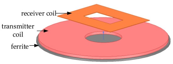
Figure 9.
Structure of single-transmitter-single-receiver WPT system.
When the receiving coil is not aligned with the transmitting coil, the output power varies. In order to study the available space area of the receiving coil in the X, Y, and Z directions when the system is able to reach an effective power, the receiving coil was misaligned in the X, Y, and Z directions, respectively, and the magnetic field simulation was utilized to observe the change of mutual inductance generated by the receiving coil via the coupled magnetic field.
When the receiving coil is misaligned in the X-axis, the position in the Z-axis direction may also change, resulting in different magnetic field strengths at different locations, which in turn affects the system’s output power. Initially, the receiver coil is located at a position that is perfectly aligned with the center of the transmitter coil, and its initial distance on the Z-axis is 5 mm. When the receiver coil is misaligned on both the Z-axis and the X-axis at the same time, the mutual inductance values and the magnetic field distributions between the receiver coil and the transmitter coil at different positions were obtained by Maxwell magnetic field simulation as shown in Figure 10, in which ΔX denotes the misalignment distance of the receiver coil on the X-axis, a negative sign denotes the misalignment distance on the X-axis, and a negative sign denotes the magnetic field strength at the X-axis. The negative sign denotes the misalignment on the negative half-axis of the X-axis, and ΔZ denotes the misalignment distance of the receiving coil in the direction of the positive half-axis of the Z-axis.
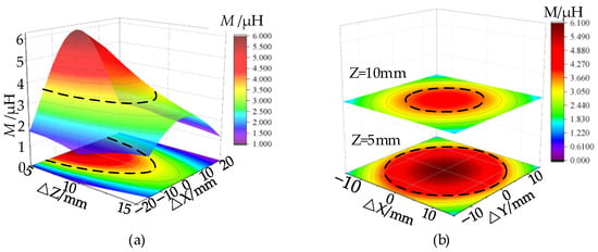
Figure 10.
Mutual inductance of receiving coil in X-axis and Y-axis. (a) Coil misalignment in the Z-axis. (b) Coil misalignment in X and Y axis.
The effective power receiving region is shown within the dashed line in the figure. From the circuit simulation, the mutual inductance range of the single-transmitter and single-receiver WPT system is (3.5, 6) μH. According to Figure 10, the available space on the Z-axis ranges from Z = 5 to 12.5 mm. When the distance between the receiver coil and the transmitter coil on the Z-axis is Z = 5 mm, the effective power receiving area on the X-axis and the Y-axis is X = ±15 mm and Y = ±15 mm, respectively. When the distance between the receiver coil and the transmitter coil on the Z-axis is Z = 10 mm, the effective power receiving area on the X-axis and the Y-axis is X = ±10 mm and Y = ±10 mm, respectively.
3.3. Single-Transmitter Dual-Receiver WPT Effective Power Receiving Region
The single-transmitter-dual-receiver WPT structure is shown in Figure 11. The coil size is the same as that of the single-transmitter-single-receiver coil, and the two receiver coils are identical.
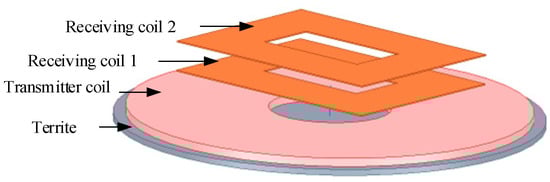
Figure 11.
Structure of single-transmitter-dual-receiver WPT system.
In a single-transmitter-dual-receiver WPT, since the position of the receiving coil is subject to some misalignment, the position of the receiving coil 1 is fixed in this study to analyze the variation of mutual inductance and power at different spatial positions when the receiving coil 2 is shifted in the lateral, longitudinal, and angular directions.
Keeping the receiving coil 1 and the transmitting coil at a distance of Z1 = 5 mm, the mutual inductance and power of the receiving coil 2 are as shown in Figure 12, with the receiving coil 2 deflected in the Z-axis. The initial position of the receiving coil 2 is perfectly aligned with the receiving coil 1, and they are stacked on top of each other. Z20 = 5 mm, ΔZ denotes the misalignment distance of the receiving coil 2 on the Z-axis, and M13 denotes the mutual inductance between the receiving coil 2 and the transmitting coil.
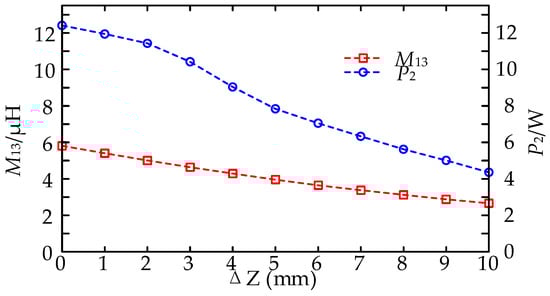
Figure 12.
Mutual inductance and power of coil 2 at different positions of Z-axis.
The mutual inductance and power of the receiving coil decreases gradually as the receiving coil gets farther and farther away from the transmitting coil. According to the previously described mutual inductance range of the single-transmitter-dual-receiver WPT system, to reach the effective power, the range must be M13 = 3–6.5 μH and the effective power receiving area of the system is Z20 + ΔZ = 5–15 mm. Compared with the single-transmitter-dual-receiver WPT system, stacking the two hollow coils enhances the magnetic field strength and increases the available space and area of the coils. This is due to the fact that when multiple hollow coils are stacked, the receiving coils not only couple with the transmitting coils, but each receiving coil also couples with each other coil, thus enhancing the receiving coils stacked on top of each other, and the misalignment range of the uppermost receiving coil will increase.
The mutual inductance of the receiving coil 2 when misaligned in the X and Y-axis is shown in Figure 13. The mutual inductance and power are maximized when there is no misalignment on the X and Y-axis, and both the mutual inductance and power decrease as the receiving coil 2 becomes more and more misalignment. According to the mutual inductance range, it is known that the effective power receiving area of the system on X and Y-axis is X = ±12.5 mm and Y = ±12.5 mm.
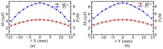
Figure 13.
Mutual inductance and power of coil 2 at different positions of X and Y axis. (a) Coil misalignment in the X-axis. (b) Coil misalignment in the Y-axis.
When the coil angle is not aligned, i.e., when the receiver coil 2 is rotated around the Z-axis, the output power is also affected. This is shown in Figure 14 for the misalignment angles α = 45° and α = 90°.
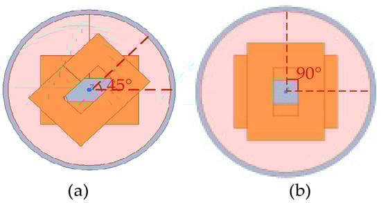
Figure 14.
Receiver coil 2 angle misalignment. (a) α = 45°. (b) α = 90°.
When the receiving coil 2 angle is not aligned and the X and Y-axis are misaligned at the same time, the mutual inductance is as shown in Figure 15. The colored region in the figure is the effective power receiving region. According to the mutual inductance of the receiving coil 2, when the angle is not aligned, it can be found that the effective receiving area is the largest when α = 0°. The effective receiving area is relatively small when α = 45° and α = 90°.
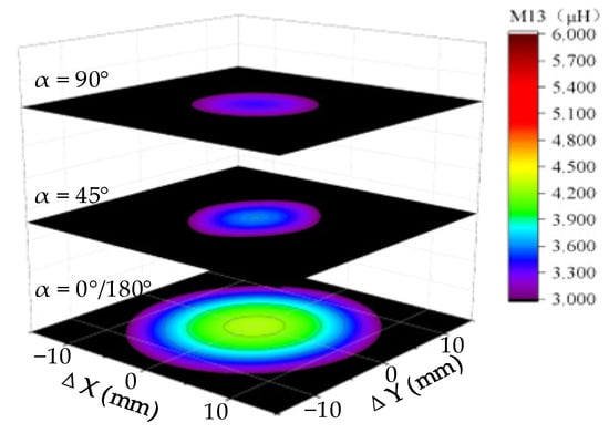
Figure 15.
Mutual inductance of receiving coil 2 at different angles.
The mutual inductance of the receiving coil 2 at different rotation angles with simultaneous Z-axis and Y-axis misalignments and with simultaneous Z-axis and X-axis misalignments is shown in Figure 16.
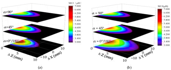
Figure 16.
Mutual inductance of X, Z and Y, and Z-axis misalignment at different angles. (a) The coil is misaligned on the X and Z-axis at the same time. (b) The coil is misaligned on the Y and Z-axis at the same time.
When the Angle of the receiving coil is misaligned, the effective power receiving area when the X and z axes are simultaneously misaligned is shown in Table 2, and the effective power receiving area when the Y and z axes are simultaneously misaligned is shown in Table 3.
Table 2.
Effective reception area when coil 2 is misaligned on the X and Z axes at the same time.
Table 3.
Effective reception area when coil 2 is misaligned on the Y and Z axes at the same time.
4. Experimental Validation
Figure 17 shows the experimental setup of the single-transmitter multiple-receiver WPT system. In Figure 17a, the debugging equipment includes a DC power supply (IT6722A), an oscilloscope (DSOX112G), a voltage probe (RIGOL RP1025D), a current probe (RIGOL RP1003C), and a DC electronic load (CH9710C). The experimental prototype includes a controller MCU (STM32F407ZGT6), a P#-type single-switch inverter (with a switch model B33N60E), an LCC compensation network, and a rectifier (SS520). Figure 17b shows the coupling mechanism. The receiver coil is 40 mm long and 30 mm wide, consisting of a rectangular air-core coil wound with Litz wire (0.2 mm wire diameter) and 15 turns. The transmitter coil has a diameter of 70 mm, wound with Litz wire (1.4 mm wire diameter) and 19 turns. Additionally, a 1 mm thick ferrite sheet is placed at the bottom of the coil to improve the coupling coefficient and shield magnetic leakage. The actual circuit parameters are consistent with those listed in Table 1.
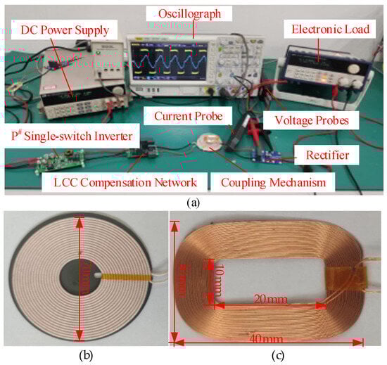
Figure 17.
Experimental platforms. (a) Experimental platforms. (b) Transmitter coil. (c) Receiving Coil.
Figure 18 shows the design details of the P# single-switch inverter. The design process begins by determining the values of the resonant inductor LX and resonant capacitor CX based on Equations (1)–(3) presented earlier. During the selection of switching devices, both voltage and current stresses are considered. Typically, the voltage stress is set to four times the input voltage, while the current stress is six times the input current. Accordingly, the B33N60E is selected as the main switching device of single-switch inverter, with key typical parameters of drain-source voltage VDS of 650 V, gate-source threshold voltage VGS(th) of 10 V, on-resistance RDS(on) of 0.083 Ω, and a body diode voltage drop of 0.9 V, providing a sufficient design margin while satisfying the performance requirements. To ensure reliable switching of the B33N60E, a gate driver circuit based on the UCC27511 was designed. The schematic diagram of the P# single-transistor inverter is shown in Figure 18a, and the corresponding Printed circuit board (PCB) layout is depicted in Figure 18b.
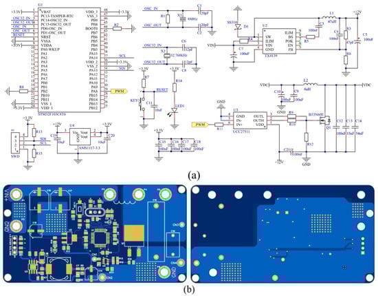
Figure 18.
Single-switch inverter design details. (a) schematic diagram of single-switch inverter. (b) PCB layout of single-switch inverter.
To accurately measure the mutual inductance between the transmitting coil and the two receiving coils under various positional conditions, an RLC bridge (Model: TongHui TH2840) was employed based on the simplified model of the single-transmitter dual-receiver magnetic coupling structure shown in Figure 19. First, ports 2 and 4 were connected in series, and the inductance between ports 1 and 3 was measured using the RLC bridge, denoted as L13. Next, the series connection between ports 2 and 4 was disconnected, and ports 2 and 3 were connected in series. The inductance between ports 1 and 4 was then measured and recorded as L14. The mutual inductance M12 was subsequently calculated using the following formula:
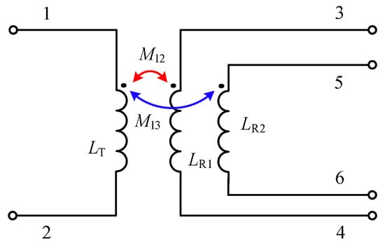
Figure 19.
Simplified model diagram of magnetic coupling mechanism.
The procedure for calculating the mutual inductance M13 follows the same method and is therefore not repeated here.
Figure 20 shows the soft-switching waveforms of the single-switch inverter switch Q. Before the gate drive signal VGS of the switch transitions from low to high, the drain-source voltage VDS of the switch has already dropped to zero. When the gate drive signal goes high, the switch Q achieves zero-voltage switching (ZVS).
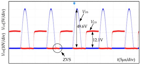
Figure 20.
MOSFET soft-switching waveform.
4.1. Experimental Analysis of Single-Transmitter-Single-Receiver WPT System
Figure 21 shows the current and voltage waveforms of the single-transmitter-single-receiver WPT system. Figures 21a and 21b are the current and voltage waveforms of the transmitting coil and rectifier side, respectively. This is consistent with the simulation circuit waveforms.
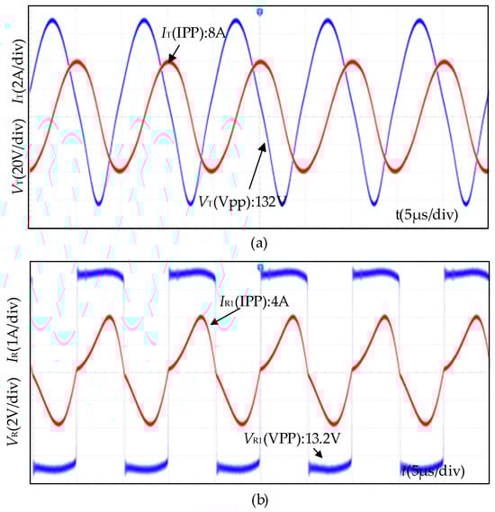
Figure 21.
Current-voltage waveforms when the receiver coil is alignment position. (a) Current and voltage waveforms of the transmitting coil. (b) Current and voltage waveforms of the rectifier input.
In the single-transmitter-single-receiver WPT system experiments, the transmitting coil is 10 mm from the receiving coil and horizontally misaligned by 10 mm. The measured transmitting coil and rectifier input current and voltage waveforms after the coil misalignment are shown in Figure 22. The system is able to achieve effective power both when the receiving coil is not misaligned and when it is misaligned within the effective power receiving region.
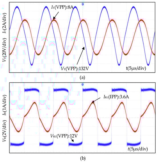
Figure 22.
Current-voltage waveforms under the receiver coil misalignment. (a) Current and voltage waveforms of the transmitting coil. (b) Current and voltage waveforms of the rectifier input.
Based on the previous analysis of mutual inductance and received power variations associated with different receiver coil positions, the mutual inductance and power reception measurements made at different positions along the Z-axis are summarized in Table 4. According to the power reception criterion P ≥ 5 W, the power boundary conditions of the WPT system can be determined, indicating that within this boundary, the received power must satisfy P ≥ 5 W. These results are consistent with the theoretical analysis and simulation findings.
Table 4.
Single-Receiver WPT system power variation values with position in the Z-axis direction.
Table 5 and Table 6 present the mutual inductance and received power for a single-receiver WPT system when the receiver coil is displaced along the X and Y axes, respectively. The analysis reveals that as the lateral displacement of the receiver coil increases in both directions, the mutual inductance and received power exhibit a decreasing trend. Specifically, along the X-axis, when the receiver coil shifts from the center position X = 0 to ±14 mm, the mutual inductance decreases from 4.28 μH to 2.65 μH, the received power reduces from 7.583 W to 2.909 W, and the efficiency reduces from 86.1 to 81.8%. Along the Y-axis, within a displacement range of ±14 mm, the mutual inductance decreases from 4.28 μH to 2.83 μH, the received power drops from 7.583 W to 3.326 W, and the efficiency reduces from 86.1 to 81.7%. These results are consistent with the theoretical analysis and simulation findings.
Table 5.
Single-Receiver WPT system power variation values with position in X-axis direction.
Table 6.
Single-Receiver WPT system power variation values with position in Y-axis direction.
4.2. Experimental Analysis of Single-Transmitter-Dual-Receiver WPT System
In the single-transmitter dual-receiver WPT system experiment, the charging distance of both receiving coils is 10 mm, and the receiving coil 2 is horizontally misaligned by 10 mm. The current and voltage waveforms after the misalignment of receiving coil 2 are shown in Figure 23. From Figure 23, it can be seen that in the single-transmitter-dual-receiver WPT system, the current-voltage waveforms when the receiving coils are misaligned are consistent with those of the single-transmitter-single-receiver WPT system.
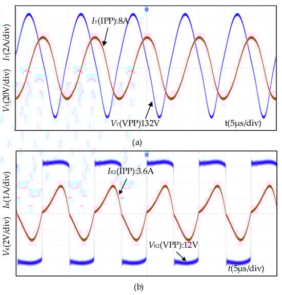
Figure 23.
Current and voltage waveforms for the misalignment of receiving coil 2. (a) The voltage waveform of the launch coil current. (b) Rectified input current-voltage waveform of the receiving coil on the 2 side.
Table 7 presents the mutual inductance and received power for a dual-receiver WPT system when the receiver coils are positioned at different locations along the Z-axis. Keep receiving coil 1 and transmitting coil 5 mm apart, and as the distance between the receiver and transmitter coils increases along the Z-axis, both the mutual inductance coefficient M and the received power P2 exhibit significant decreasing trends. Specifically, when the receiver coil distance increases from 5 mm to 15 mm, the mutual inductance decreases from 6 μH to 2.66 μH while the corresponding received power drops from 12.41 W to 4.36 W. These results align with the theoretical analysis and simulation findings.
Table 7.
Dual-receiver WPT system power variation values with position in Z-axis direction.
Table 8 and Table 9 present the mutual inductance and received power for a dual-receiver WPT system when the receiver coils are positioned at different locations along the X and Y axes, respectively. Keep receiving coil 1 and transmitting coil 5 mm apart, and the analysis indicates that along the X-axis, as receiver coil 2 shifts laterally from the center position X = 0 to ±14 mm, the mutual inductance decreases from 4.29 μH to 3.58 μH, the received power drops from 9.07 W to 3.87 W, and the efficiency reduces from 85.3 to 80.8%. Along the Y-axis, when the receiver coil is displaced within the ±14 mm range, the mutual inductance decreases from 4.29 μH to 2.81 μH, the received power declines from 7.07 W to 4.702 W, and the efficiency reduces from 85.3 to 80.6%. These results are consistent with the theoretical analysis and simulation findings.
Table 8.
Dual-receiver WPT system power variation values with position in X-axis direction.
Table 9.
Dual-receiver WPT system power variation values with position in Y-axis direction.
When receiver coil 2 in the dual-receiver WPT system is positioned identically to the receiver coil in the single-receiver WPT system, the received power in the dual-receiver system is significantly higher. This result indicates that the effective operating region of the system is notably expanded when utilizing stacked hollow receiver coils. In the dual-receiver WPT system, the power boundary conditions are determined as follows: X2min = −12 mm, X2max = 12 mm, Y2min = −12 mm, Y2max = 12 mm. Compared to the power boundary conditions of the single-receiver WPT system, this range is significantly expanded. This suggests that, after optimizing the receiver coil layout, the dual-receiver WPT system can more effectively capture transmitted power, thereby enhancing overall system performance.
Table 10 presents a comparison of the critical mutual inductance and maximum power transmission in the Z-axis direction for both the single-receiver and dual-receiver WPT systems.
Table 10.
Comparison of single-receiver and dual-receiver WPT systems.
5. Conclusions
This paper investigates the effective reception area of a one-to-many wireless energy transmission (WPT) system based on a single-switch inverter P#LCC-S with receiver coil misalignment. Simulation circuit models for both single-transmitter-single-receiver and single-transmitter-dual-receiver WPT systems were developed using MATLAB/Simulink R2022b. The mutual inductance ranges that enable effective power transfer are identified as (3.5, 6) μH for the single-transmitter-single-receiver system and (3, 6.5) μH for the single-transmitter-dual-receiver system. Furthermore, finite element simulation models for both coupling mechanisms reveal the mutual inductance variation under different coil positions. The effective power reception area along the Z-axis for the single-transmitter-single-receiver system was determined to be Z = 5–12.5 mm. For the single-transmitter-single-receiver system, when the receiver coil is positioned at Z = 5 mm, the effective power reception areas along the X-axis and Y-axis are X = ±15 mm and Y = ±15 mm, respectively. At Z = 10 mm, the effective power reception areas along the X-axis and Y-axis are X = ±10 mm and Y = ±10 mm, respectively. For the single-transmitter-dual-receiver system, the effective power reception area for Z = 5–14 mm is maximized at X = ±15 mm and Y = ±10 mm. Experimental validation on the test platform confirms that the receiving coil remains within the effective power receiving region under misalignment conditions, ensuring stable power output.
Author Contributions
Conceptualization, K.G. and Y.Y.; Methodology, K.G., X.Z. and Y.Y.; Software, J.L.; Validation, X.Z., J.L. and Z.L.; Investigation, Z.L.; Writing—original draft, X.Z.; Writing—review and editing, K.G. and Y.Y.; Visualization, J.L.; Project administration, Z.L. All authors have read and agreed to the published version of the manuscript.
Funding
This research was funded by Natural Science Foundation of Chongqing, China grant number CSTB2022NSCQ-MSX0997 and CSTB2022NSCQ-MSX0382, Project of Chongqing University of Technology Research Start-up Fund, grant number KJQN202201103, and Graduate Innovation Project of Chongqing University of Technology, grant number gzlcx20243107 and gzlcx20243091.
Data Availability Statement
The original contributions presented in this study are included in the article. Further inquiries can be directed to the corresponding author.
Acknowledgments
This research was supported by Haixiao Li, Shiyun Xie, and Lu Zhang in the materials used for the experiments and theoretical analysis.
Conflicts of Interest
The authors declare no conflicts of interest.
References
- Li, X.; Wang, C.; Wang, H.; Dai, X.; Sun, Y.; Hu, A.P. A Robust Wireless Power Transfer System with Self Alignment Capability and Controllable Output Current for Automatic Guided Vehicles. IEEE Trans. Power Electron. 2018, 38, 11898–11906. [Google Scholar]
- Li, Y.; Mai, R.; Lu, L.; He, Z. A Novel IPT System Based on Dual Coupled Primary Tracks for High Power Applications. J. Power Electron. 2016, 16, 111–120. [Google Scholar] [CrossRef]
- Yang, Y.; Cao, G.; Li, H. A Positioning and Direction-Guided Approach of the WPT System Based on the Triple-U Coil. IEEE Sens. J. 2023, 23, 26473–26485. [Google Scholar]
- Luo, Y.; Dai, Z.; Yang, Y. A Single-Transmitter Multi-Receiver Wireless Power Transfer System with High Coil Misalignment Tolerance and Variable Power Allocation Ratios. Electronics 2024, 13, 3838. [Google Scholar] [CrossRef]
- Xie, S.; Wu, L.; Zhang, X.; Huang, J.; Li, L. Misalignment-Tolerant Wireless Power Transfer System Based on Double-Layer Quadrature Double-D Coil With Magnetic Field Control. IEEE Trans. Transp. Electrification 2019, 10, 9945–9958. [Google Scholar]
- Peng, C.; Chen, Z.; Liu, Z.; Wang, J.-F.; Liang, J.; Li, C.; Tao, S.; Li, J. On the load-independence of a multi-receiver wireless power transfer system. IEEE Microw. Wirel. Compon. Lett. 2019, 29, 563–565. [Google Scholar] [CrossRef]
- Qi, C.; Miao, H.; Lang, Z.; Chen, X. A generalized methodology to generate, amplify and compensate multi-frequency power for a single-inverter-based MF-MR-S-WPT system. IEEE Access 2020, 8, 181513–181525. [Google Scholar]
- Li, Y.; Mai, R.; Lin, T.; Sun, H.; He, Z. A novel WPT system based on dual transmitters and dual receivers for high power applications: Analysis, design and implementation. Energies 2017, 10, 174. [Google Scholar] [CrossRef]
- Kim, K.W.; Lee, H.S.; Lee, J.W. Opportunistic waveform scheduling for wireless power transfer with multiple devices. IEEE Trans. Wirel. Commun. 2020, 19, 5651–5665. [Google Scholar] [CrossRef]
- Pahlavan, S.; Shooshtari, M.; Jafarabadi Ashtiani, S. Star-shaped coils in the transmitter array for receiver rotation tolerance in free-moving wireless power transfer applications. Energies 2022, 15, 8643. [Google Scholar] [CrossRef]
- Pahlavan, S.; Jafarabadi-Ashtiani, S.; Mirbozorgi, S.A. Maze-based scalable wireless power transmission experimental arena for freely moving small animals applications. IEEE Trans. Biomed. Circuits Syst. 2024, 19, 120–129. [Google Scholar]
- Zhu, Z.; Yuan, H.; Zhang, R.; Yang, A.; Wang, X.; Rong, M. Parity–Time Symmetric Model and Analysis for Stable Multi-Load Wireless Power Transfer. World Electr. Veh. J. 2021, 12, 226. [Google Scholar] [CrossRef]
- Liu, W.; Chau, K.T.; Lee, C.H.T.; Jiang, C.; Han, W. A switched-capacitorless energy-encrypted transmitter for roadway-charging electric vehicles. IEEE Trans. Magn. 2018, 54, 1–6. [Google Scholar]
- An, H.; Yuan, J.; Li, J.; Cao, L. Design and analysis of omnidirectional receiver with multi-coil for wireless power transmission. Electronics 2022, 11, 3103. [Google Scholar] [CrossRef]
- Duong, Q.-T.; Okada, M. Maximum Efficiency Formulation for Multiple-Input Multiple-Output Inductive Power Transfer Systems. IEEE Trans. Microw. Theory Tech. 2018, 60, 3463–3477. [Google Scholar]
- Kim, S.; Hwang, S.; Kim, S.; Lee, B. Investigation of Single-Input Multiple-Output Wireless Power Transfer Systems Based on Optimization of Receiver Loads for Maximum Efficiencies. Trans. China Electrotech. Soc. 2018, 18, 145–153. [Google Scholar]
- Yang, Y.; Guo, K.; Guo, Q.; Wang, Y.; Xie, S. Research and design of single-switch inverter wireless power transfer system for grid flat spiral pad coils. Chin. J. Sci. Instrum. 2023, 44, 161–174. [Google Scholar]
- Cheng, C.; Lu, F.; Zhou, Z.; Li, W.; Deng, Z.; Li, F.; Mi, C.C. A Load-Independent LCC-Compensated Wireless Power Transfer System for Multiple Loads with a Compact Coupler Design. IEEE Trans. Ind. Electron. 2020, 67, 4507–4515. [Google Scholar]
- Zhang, Z.; Pang, H.; Wang, J. Multiple Objective-Based Optimal Energy Distribution for Wireless Power Transfer. IEEE Trans. Magn. 2018, 54, 1–5. [Google Scholar]
- Zhang, P.; Gong, L.; Ma, X.; Ma, X.; Huang, B. Design and Analysis of Compensation Network for Dual-Coil Wireless Energy Transmission System with Variable Gain and Constant Voltage Characteristics. J. Electrotechnol. 2024, 39, 1256–1269, 1283. [Google Scholar]
- Arteaga, J.M.; Aldhaher, S.; Kkelis, G.; Kwan, C.; Yates, D.C.; Mitcheson, P.D. Dynamic Capabilities of Multi-MHz Inductive Power Transfer Systems Demonstrated with Batteryless Drones. IEEE Trans. Power Electron. 2019, 34, 5093–5104. [Google Scholar]
- Cai, C.; Wang, J.; Luo, Y.; Rao, Y.; Zhang, P.; Zang, T.; Lin, H.; Liu, L. Multi-State Voltage Balancing of UAV’s Cell String: A Reconfigurable WPT Based Multiport Hybrid Charging Approach. IEEE Trans. Ind. Electron. 2025, 72, 266–277. [Google Scholar]
- Yang, Y.; Zhang, X.; Luo, L.; Xie, S.; Zhou, Q. Research on High Power Factor Single Tube Variable Structure Wireless Power Transmission. World Electr. Veh. J. 2021, 12, 214. [Google Scholar] [CrossRef]
- Yang, Y.; Jia, W.; Liang, D.; Xue, J.; Li, Y. A Self-Switching Wireless Power Transfer System Based on Hybrid Topology of LCC-LCC/S with Constant Current and Constant Voltage. Trans. China Electrotech. Soc. 2023, 38, 4823–4837, 4852. [Google Scholar]
- Yang, Y.; Zhang, X.; Guo, K.; Zhang, W.; Xie, S. Optimization of a Single-Switch Wireless Power Transfer Circuit Based on a Multi-Coil Array. Electronics 2023, 12, 2213. [Google Scholar] [CrossRef]
- Chen, K.; Zhao, Z.; Liu, F.; Yuan, L. Analysis of Resonant Topology for Bi-directional Wireless Charging of Electric Vehicle. Autom. Electr. Power Syst. 2017, 41, 66–72. [Google Scholar]
Disclaimer/Publisher’s Note: The statements, opinions and data contained in all publications are solely those of the individual author(s) and contributor(s) and not of MDPI and/or the editor(s). MDPI and/or the editor(s) disclaim responsibility for any injury to people or property resulting from any ideas, methods, instructions or products referred to in the content. |
© 2025 by the authors. Published by MDPI on behalf of the World Electric Vehicle Association. Licensee MDPI, Basel, Switzerland. This article is an open access article distributed under the terms and conditions of the Creative Commons Attribution (CC BY) license (https://creativecommons.org/licenses/by/4.0/).