Review

Powertrain in Battery Electric Vehicles (BEVs): Comprehensive Review of Current Technologies and Future Trends Among Automakers

by
Ernest Ozoemela Ezugwu
1,
Indranil Bhattacharya
2,*,
Adeloye Ifeoluwa Ayomide
1,
Mary Vinolisha Antony Dhason
1,
Babatunde Damilare Soyoye
1 and
Trapa Banik
1
1
Department of Electrical and Computer Engineering, Tennessee Technological University, Cookeville, TN 38505, USA
2
Department of Electrical and Computer Engineering, Binghamton University, 4400 Vestal Pkwy E, Binghamton, NY 13902, USA
*
Author to whom correspondence should be addressed.
World Electr. Veh. J. 2025, 16(10), 573; https://doi.org/10.3390/wevj16100573
Submission received: 25 July 2025 / Revised: 30 August 2025 / Accepted: 30 September 2025 / Published: 10 October 2025
(This article belongs to the Section Propulsion Systems and Components)

Abstract

Battery Electric Vehicles (BEVs) technology is rapidly emerging as the cornerstone of sustainable transportation, driven by advancements in battery technology, power electronics, and modern drivetrains. This paper presents a comprehensive review of current and next-generation BEV powertrain architectures, focusing on five key subsystems: battery energy storage system, electric propulsion motors, energy management systems, power electronic converters, and charging infrastructure. The review traces the evolution of battery technology from conventional lithium-ion to solid-state chemistries and highlights the critical role of battery management systems in ensuring optimal state of charge, health, and safety. Recent innovations by leading automakers are examined, showcasing advancements in cell formats, motor designs, and thermal management for enhanced range and performance. The role of power electronics and the integration of AI-driven strategies for vehicle control and vehicle-to-grid (V2G) are analyzed. Finally, the paper identifies ongoing research gaps in system integration, standardization, and advanced BMS solutions. This review provides a comprehensive roadmap for innovation, aiming to guide researchers and industry stakeholders in accelerating the adoption and sustainable advancement of BEV technologies.

1. Introduction

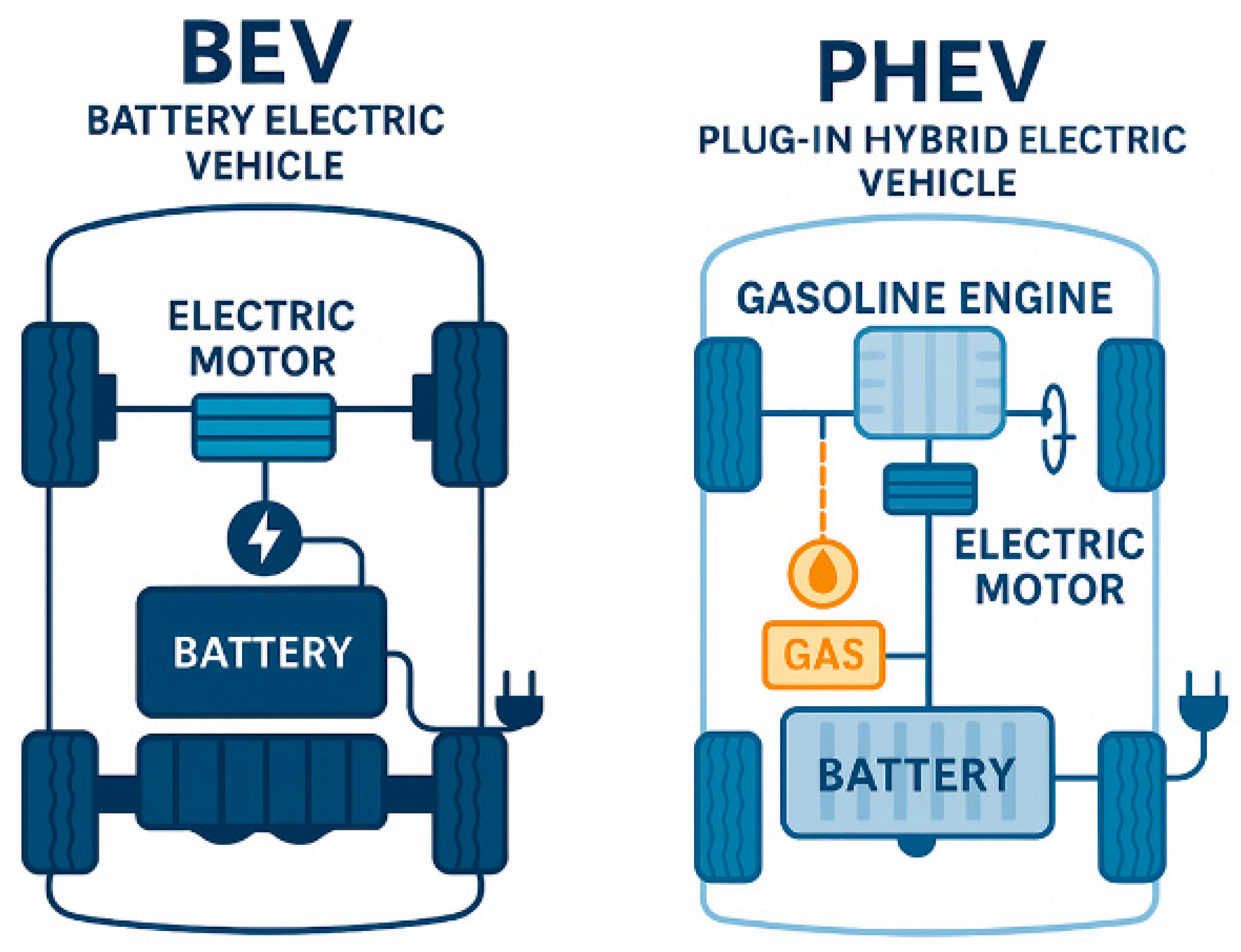
Electric vehicle (EV) technology has deep historical roots, with early battery-powered cars in the late 19th century preceding the dominance of gasoline automobiles. After a long dormancy through the mid-20th century, modern electrification began with hybrid electric vehicles (HEVs) in the 1990s, marking a turning point in reducing vehicular emissions. The 1997 launch of the Toyota Prius demonstrated that combining an internal combustion engine (ICE) with a battery and motor could drastically improve fuel efficiency and lower emissions [1]. HEVs served as a transitional technology, bridging conventional gasoline cars and fully electric vehicles by offering improved fuel economy and partial zero-emission driving [2,3]. Over time, plug-in hybrid electric vehicles (PHEVs) extended electric-only driving range while retaining an ICE for backup. These gradual advances in battery capacity, power electronics, and energy management laid the groundwork for today’s Battery Electric Vehicles (BEVs), which rely exclusively on electrochemical energy for propulsion and eliminate fossil fuel use entirely. This evolution has been fueled by growing concerns over climate change, fossil fuel scarcity, and stringent emission regulations by many nations of the world [4]. Figure 1 illustrates the evolving trends in electric vehicle development, while Figure 2 compares simplified powertrain layouts of BEVs and HEVs.
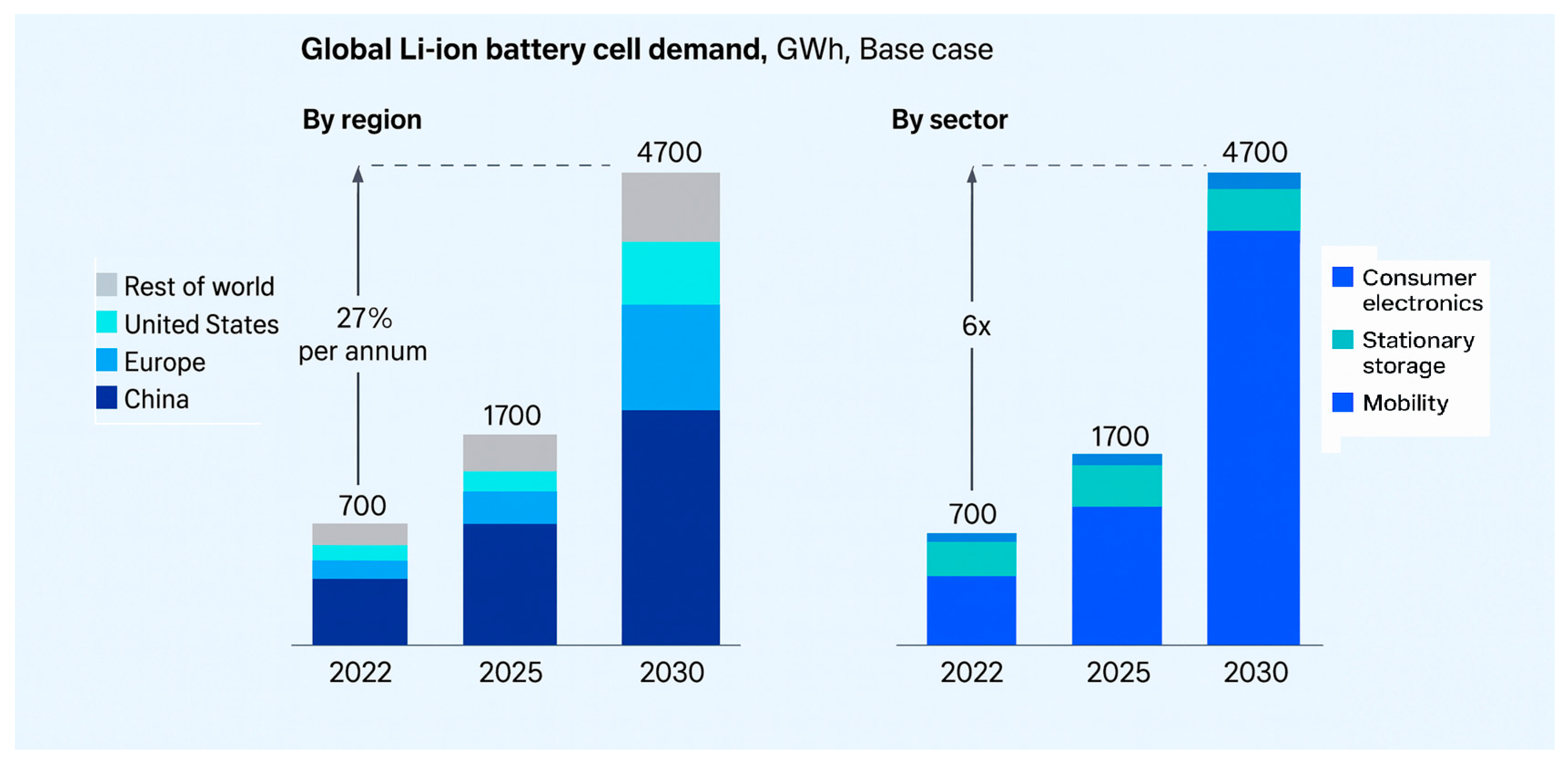
This transformation supports the global yearnings for an eco-friendly urban environment, improved air quality, low noise pollution, and healthier communities. The widespread adoption of BEVs is a critical step being taken by countries of the world in building sustainable ecosystems and combating the escalating threats of global warming [5,6]. Behind the quiet acceleration and zero emissions of modern BEVs lies an increasingly powerful and efficient battery pack [2,7]. As illustrated in Figure 3, battery demand is projected to surge from approximately 700 GWh in 2022 to nearly 1700 GWh in 2025 and is expected to rise to 4700 GWh by 2030; this is primarily driven by the rapid adoption of electric vehicles [8,9]. Electric mobility, as shown in Figure 3, is not only increasing battery consumption but also propelling advancements in battery technology. This trend is accelerating economies of scale and ushering in a new era where zero-emission vehicles dominate roadways worldwide [9,10,11]. This takes us to the trends or transitions in technologies that gave birth to the battery electric vehicle or the full electric vehicle as we have it now.

1.1. Review Methodology

We conducted a systematic review aligned with PRISMA 2020 to ensure transparent, reproducible reporting. Searches spanned MDPI Open Access Journal, IEEE Xplore, ScienceDirect, Web of Science, Scopus, and Google Scholar (2015–2025), using sentence combinations covering EVs, batteries, motors, power electronics, EMS, charging, and other related terms. We augmented this with backward/forward citation chasing, targeted retrieval of standards and technical guidance (e.g., SAE/ISO), agency and consortium reports (e.g., IEA/DOE), and industry white papers, data sheets, and teardowns where they provided primary measurements or architectural detail.
Eligibility required substantive treatment of BEV powertrain subsystems or integration; we included peer-reviewed articles, high-quality reviews, and rigorously documented industry standards sources; we excluded purely promotional materials and non-English sources. Titles/abstracts were screened against predefined criteria, followed by full-text assessment. Study credibility was appraised using ROBIS alongside domain checks.
Data were extracted with standardized forms and harmonized to enable cross-study comparison of key metrics (battery chemistry/energy density, motor and inverter efficiency, converter topologies, EMS algorithms, and charging performance. The referenced journals were refreshed through 2025 to capture late-breaking developments.
In this review, we provide a comprehensive examination of BEV powertrain technology, focusing on five core subsystems: the battery energy storage system, electric propulsion motors, energy management systems (vehicle control and battery management), power electronic converters, and charging infrastructure. We trace the evolution of each subsystem, highlight state-of-the-art developments, and compare approaches among leading automakers. Where relevant, we also discuss emerging alternatives such as fuel cell electric vehicles (FCEVs) to contextualize BEV advances. Our goal is to identify the current state-of-the-art and future trends in BEV powertrains, as automakers chart technology roadmaps toward safer, higher-performance, and more sustainable electric mobility. The following sections are organized as follows: in-depth analysis of each technical subsystem (Sections on Battery, Motors, EMS, Power Electronics, Charging), followed by a brief overview of FCEV technology, a comparison of automaker technology roadmaps, including a tabular comparison of key metrics, and finally, future trends and conclusions. This structured approach allows each core subsystem to be discussed in depth as a standalone section before synthesizing overarching findings and future directions.

1.2. The Rise of Battery Electric Vehicles (BEVs)
The recent breakthrough and rapid growth of BEVs can be attributed to the advancements in lithium-ion battery chemistry with increased energy density, significant cost reductions, and the widespread development of charging infrastructure [12]. Early pioneers of modern BEVs include Tesla Roadster 2008, Tesla Model S 2012, Mitsubishi i-MiEV 2009, Nissan Leaf 2010, and BYD e6 taxi fleets beginning 2010. BMW (i3, 2013) and Mercedes-Benz (B-Class Electric Drive, 2014) expanded the industry soon after, and BEVs became highly in demand. In plug-in hybrids, BYD’s F3DM (2008) was among the earliest mass-produced PHEVs. GM’s modern mass-market efforts followed in the 2010s with Volt PHEV 2010 and Bolt EV 2016 [13,14,15,16,17]. Pioneer BEV automakers commercialized BEVs on a large scale, setting new standards for range, efficiency, and performance among other automakers.
Tesla played a visible role in reshaping the BEV landscape with the Roadster (2008), demonstrating that high-performance BEVs are feasible [18]. Tesla’s new development of advanced battery technology—the 4680 cylindrical battery cells and structural battery packs has further enhanced vehicle performance. Subsequent models (Model S/X/3/Y) helped popularize long-range BEVs and frequent over-the-air improvements; however, leadership is now distributed across multiple automakers (e.g., BYD, Hyundai–Kia, Volkswagen Group, Mercedes-Benz), and “standard-setting” is shared across the industry. In North America, many automakers are converging on the North America Climate Submit (NACS-2025) and access to high-reliability fast-charging networks, while global BEV market leadership varies by region and over time [19]. Moreover, use cases should guide range targets and battery sizing: very long-range packs increase vehicle mass, cost, and life-cycle, whereas smaller “right-sized” packs paired with reliable fast charging can minimize environmental impact and total cost of ownership.
Nissan, with the launch of the Nissan Leaf in 2010, introduced one of the world’s first mass-market electric cars [20]. Nissan Leaf demonstrated that practical, affordable BEVs could achieve widespread adoption, leading to continuous improvements in battery capacity, range, and charging speeds. BMW entered the BEV market with the BMW i3 (2013) [21], a model that showcased innovative carbon-fiber-reinforced construction and a lightweight design to optimize efficiency. More recently, BMW has expanded its electric vehicle portfolio with models such as the i4 and iX, leveraging advancements in battery chemistry and electric drivetrains [22].
In response to the growing demand for BEVs and the market expansion, traditional automakers are quickly shifting to BEV platforms and powertrains [7]. As shown in Figure 3 (Global Li-ion battery cell demand, base case), worldwide battery cell demand is projected to grow from 700 GWh in 2022 to 4700 GWh by 2030, with mobility (EVs) driving the vast majority of the increase while stationary storage steadily expands its share. Regionally, growth is led by China, with accelerating contributions from Europe and the United States, mirroring policy support and rapid manufacturing build-out.
Figure 3. Projected global battery cell demand growth according to regions and applications from 2022 to 2030, primarily driven by electric vehicles. Reprinted from [23].
Wevj 16 00573 g003
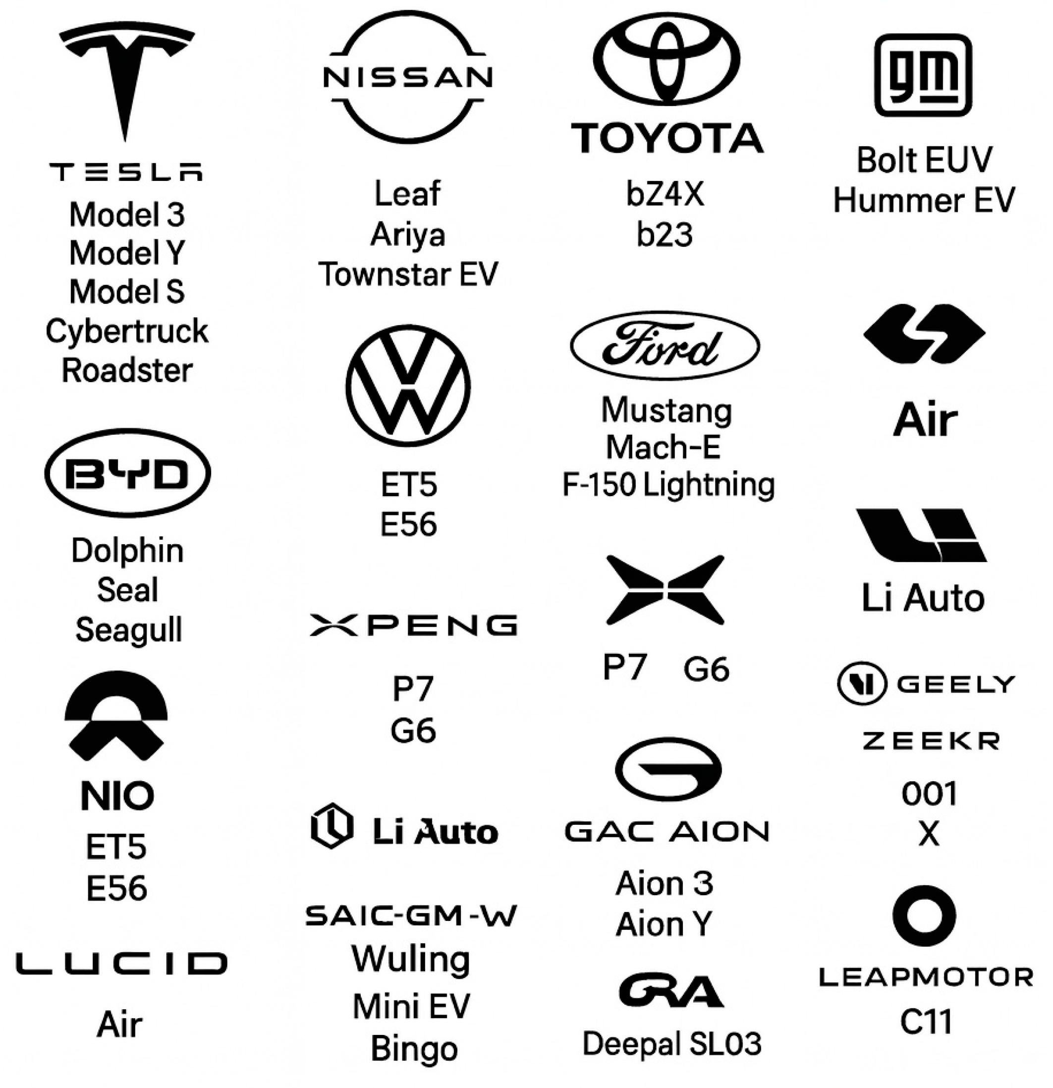
Figure 4 shows some automakers producing BEVs with some of their popular models. As of 2025, Tesla’s BEV lineup includes the compact Model 3, Model Y crossover, flagship Model S and Model X, Cybertruck pickup, and an upcoming Roadster sports car promising 600-mile range and 0–60 mph in under two seconds [24]. Nissan’s EV lineup in 2025 includes the Compact Leaf, Ariya, and Townstar [25]. Volkswagen (VW) introduced its ID series, which includes the ID.3, ID.4, and ID.Buzz [26].
Ford has made a significant impact with the Mustang Mach-E, a high-performance electric SUV, and the F-150 Lightning [24], an electric version of America’s best-selling truck. General Motors (GM) has developed the Ultium battery platform, designed to power a wide range of vehicles, from the Chevrolet Bolt EUV to the GMC Hummer EV [27,28]. The Ultium platform allows for flexible battery configurations, increased range, and fast-charging capabilities [27].
Rivian has developed adventure-oriented electric vehicles, such as the R1T (electric pickup truck) and R1S (electric SUV), featuring quad-motor drivetrains, off-road capabilities, and advanced regenerative braking [29,30].
Lucid Motors has positioned itself as a leader in efficiency with the Lucid Air, boasting over 500 miles of range per charge and industry-leading battery technology [29].
BYD, one of China’s largest EV manufacturers, has pioneered the use of blade battery technology [31]. They have Ocean Series—BYD Dolphin, Seal, Sealion, Sharks, and other models. NIO, another Chinese automaker, has introduced battery-swapping technology, allowing users to replace depleted batteries in minutes instead of waiting for charging, addressing range anxiety and infrastructure challenges [32]. They have ET5, ETS7, ETS9, the EC series, and the ES series. Many other automakers from different parts of the world are working on the adoption and advancement of the BEV system to completely eliminate carbon emissions, increase efficiency, safety, and drive range.

1.3. Core Subsystems of BEV Powertrains

As automakers compete to optimize BEV performance, there are key components that drive the design and integration of BEV powertrain systems [7]. The powertrain of a Battery Electric Vehicle (BEV) is composed of five essential subsystems: Battery Energy Storage Systems, Electric Propulsion Motors, Energy Management Systems, Power Electronic Converters, and Charging Infrastructure [33]. These five components form the structure of this review paper.
The Battery Energy Storage System includes the high-voltage lithium-ion battery pack and the Battery Management System (BMS), which oversees state of charge (SOC), State of Health (SOH), cell balancing, thermal protection, and overall battery safety [34].
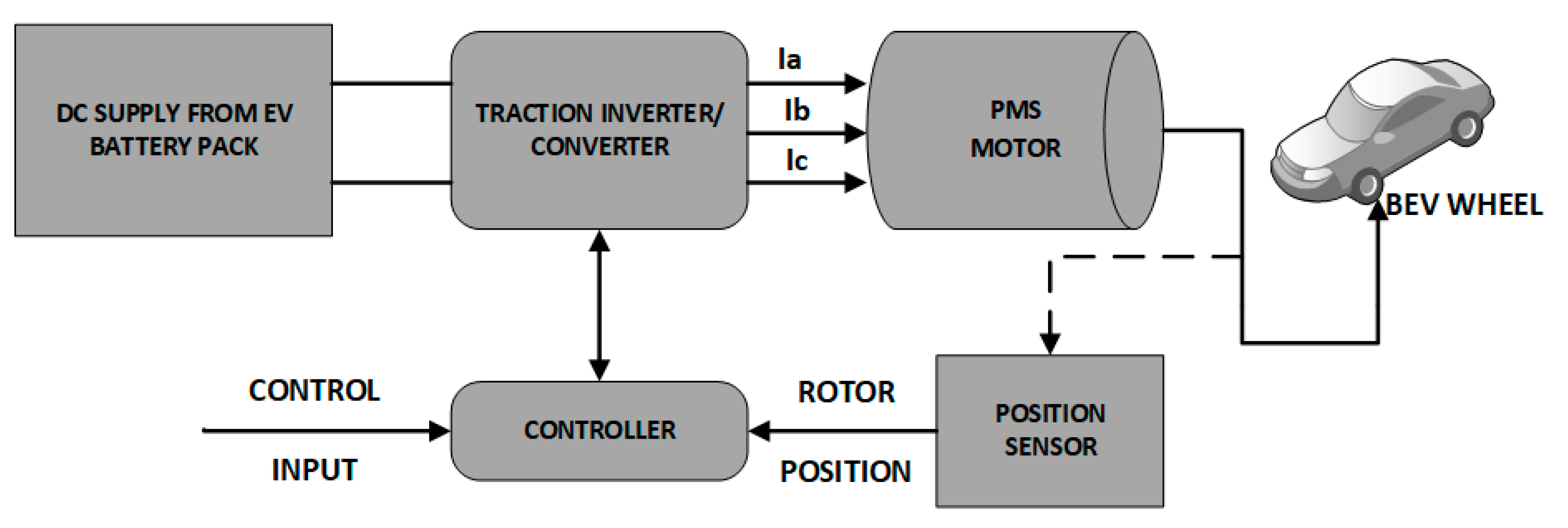
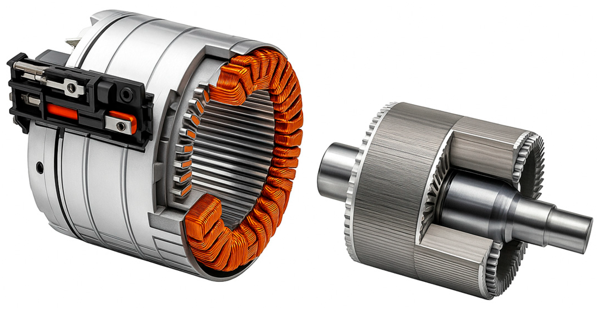
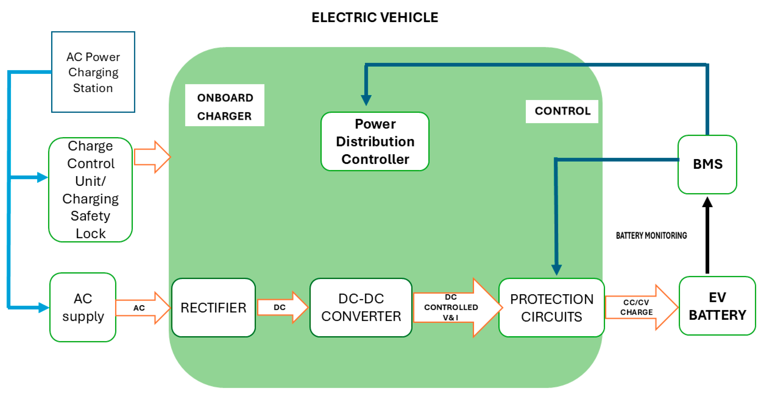
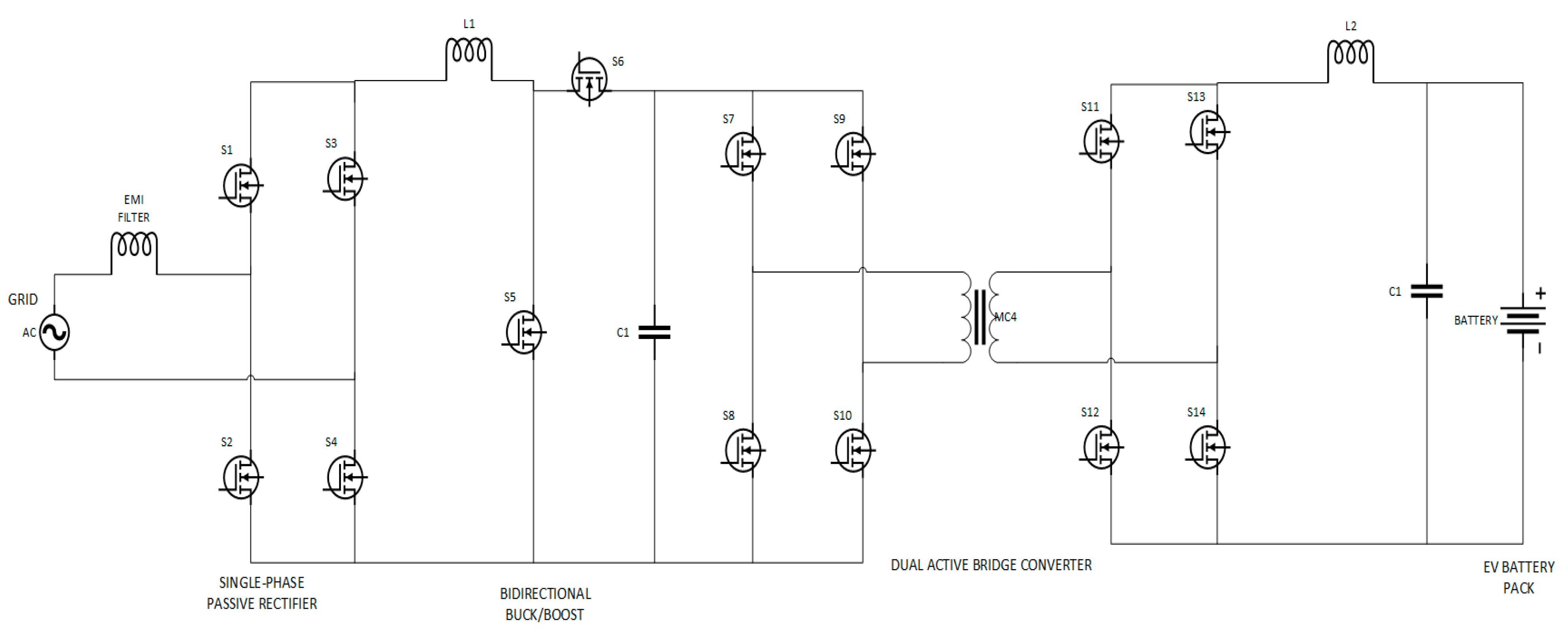
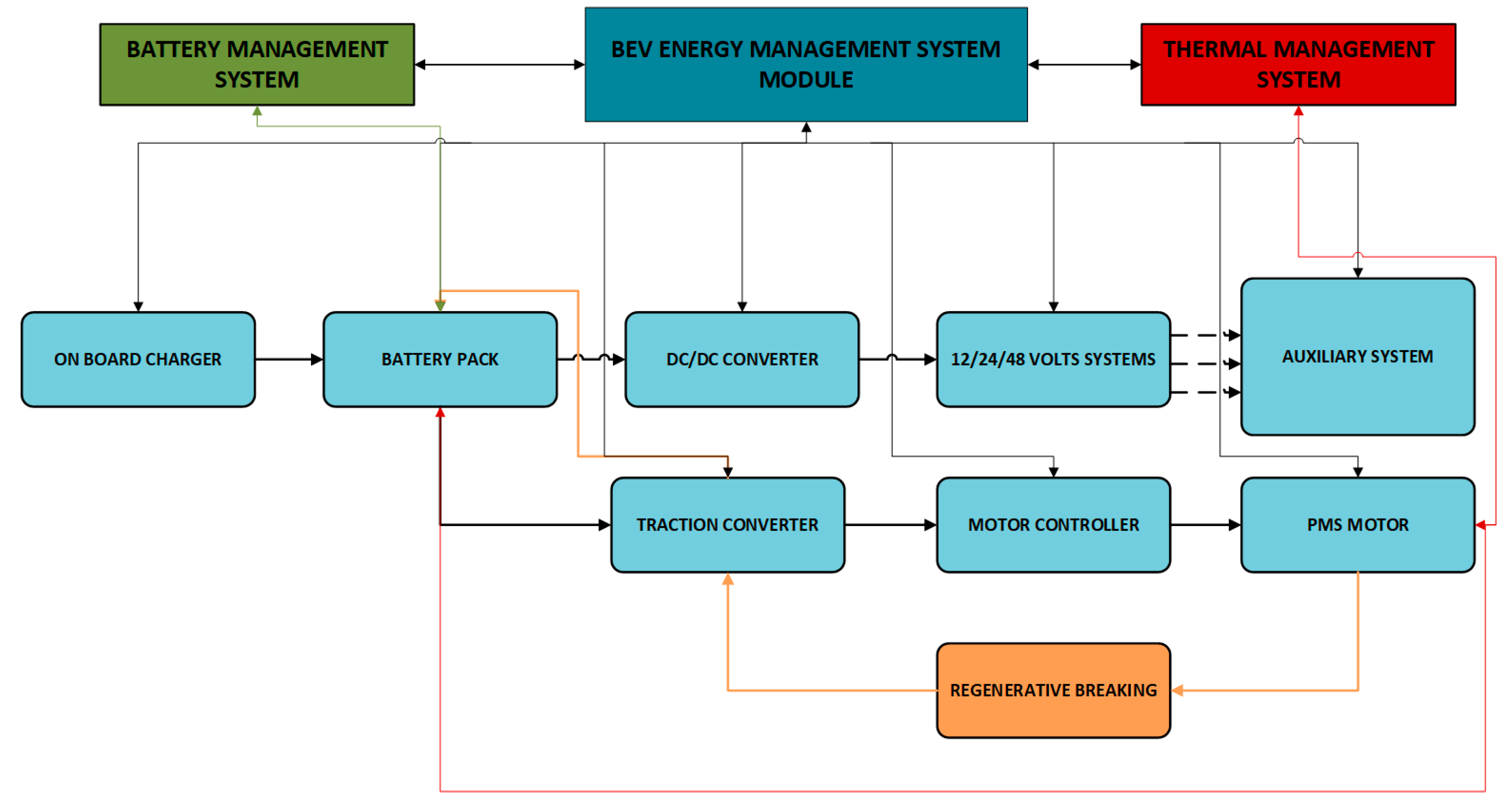
Power Electronics manages the flow and conversion of electrical energy through three main components: a DC/DC converter to supply 12 V auxiliaries, an onboard charger that converts AC from charging stations into DC for battery storage, and a motor inverter/controller that converts DC to three-phase AC to drive the traction motor and enables regenerative braking [35]. The Electric Propulsion Motor subsystem consists of a primary traction motor (typically three-phase AC) and additional auxiliary motors (optional). The motor delivers torque directly to the wheels via a reduction gearbox and differential, converting electrical energy into mechanical propulsion [35]. The Energy Management System (EMS) or central Electronic Control Unit (ECU) governs the vehicle acceleration, regenerative braking, battery health monitoring, and thermal regulation. When the driver presses the accelerator, the ECU/EMS commands the inverter to energize the motor windings and produce motion. During deceleration, regenerative braking systems convert kinetic energy back into electrical energy, recharging the battery [36]. Finally, the Charging Infrastructure connects the vehicle to external power sources via AC or DC charging ports. It works in tandem with onboard charging systems to safely manage the charging process.
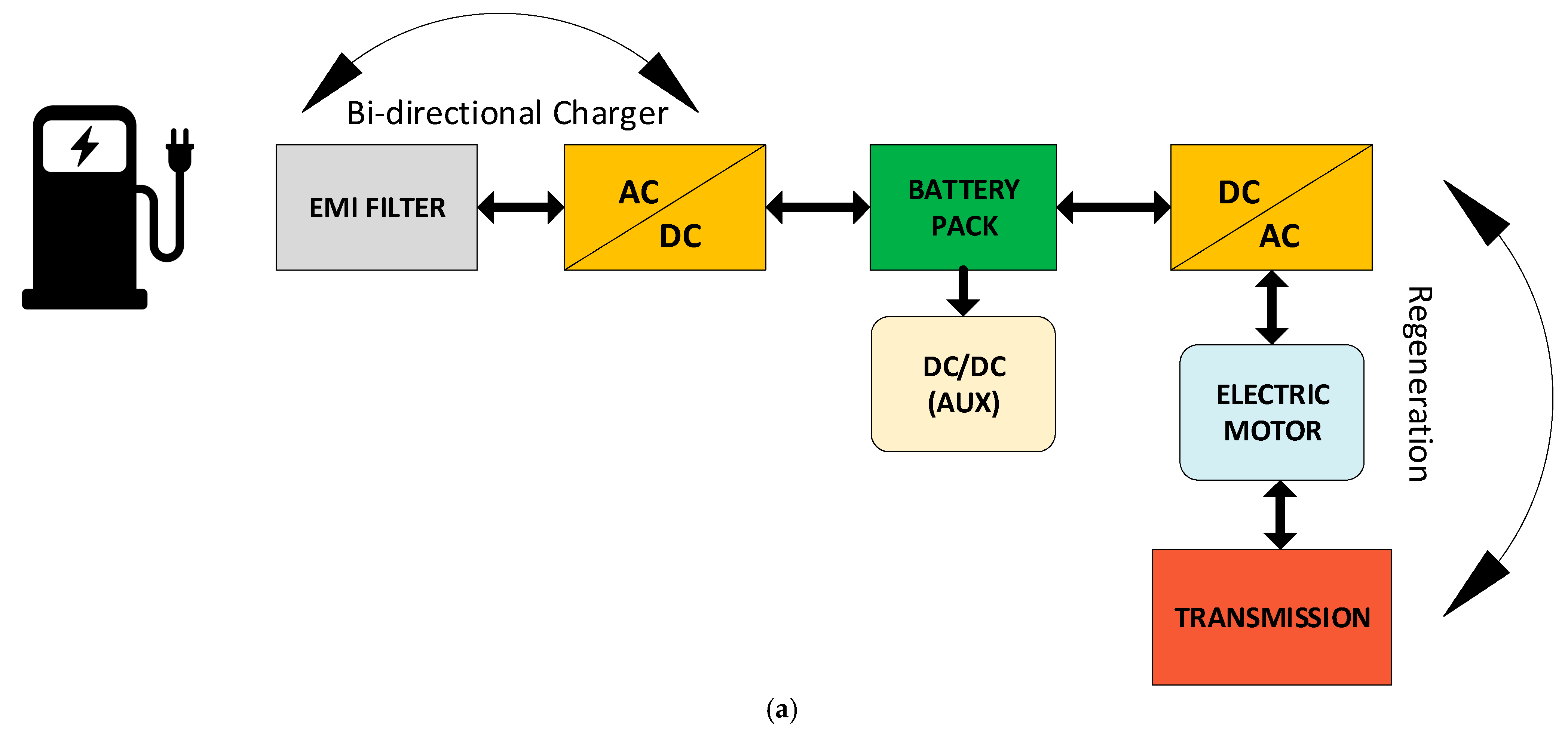
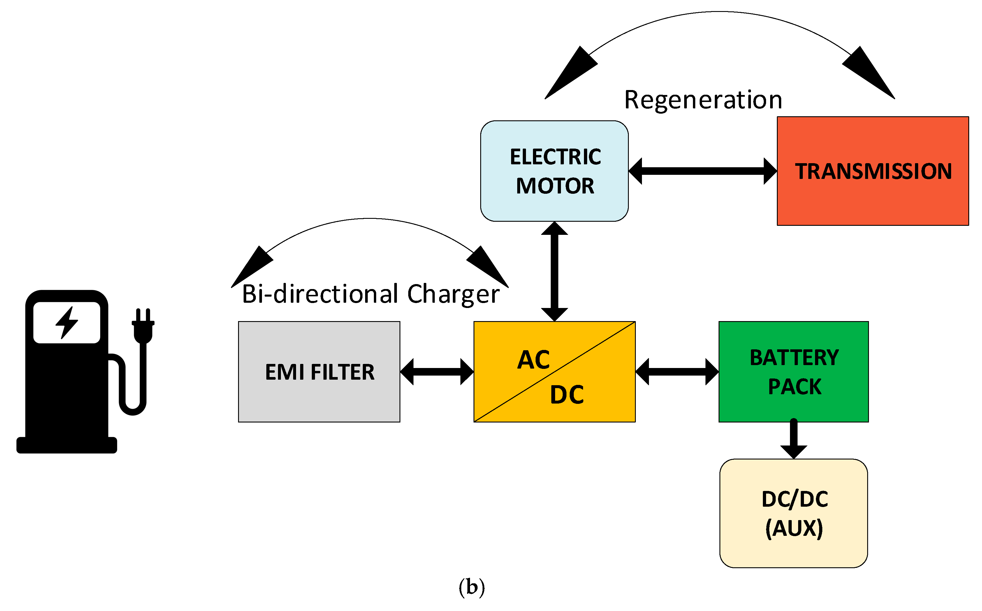
Together, these five powertrain subsystems are seamlessly integrated to deliver instant torque, high efficiency, advanced thermal control, and energy recovery capabilities not possible in traditional internal combustion engine (ICE) drivetrains [37]. Figure 5. Shows the flow of the powertrain from the charging infrastructure through the battery storage system to power electronics, then to the electric motor and to the transmission drivetrain. Each of the subsystems is discussed in detail in the following sections of this review paper.

2. Battery Energy Storage Systems

A battery is a device that stores chemical energy and converts it into electrical energy through electrochemical reactions. It consists of one or more electrochemical cells, each made up of three main components, as follows:
Anode (Negative Electrode): Releases electrons during discharge (oxidation).
Cathode (Positive Electrode): Accepts electrons during discharge (reduction).
Electrolyte: A medium that allows ions to move between the anode and cathode, completing the internal circuit.
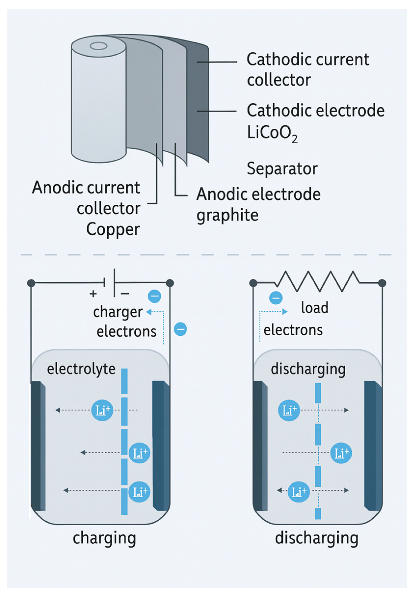
Figure 6 illustrates the internal structure and electrochemical processes in a lithium-ion battery during charging and discharging.
Anode ( discharge ) :   ( LiC 6 C 6 + Li + + e )
Cathode   ( discharge ) :   ( LiCoO 2 CoO 2 + Li + + e )
Overallreaction : ( LiCoO 2 + C 6 CoO 2 + LiC 6 )
  • Charging Process
  • When the battery is connected to a charger, an external electric field forces lithium ions (Li+) to move from the cathode, see Equation (1). through the electrolyte and separator toward the anode (graphite). At the same time, electrons flow through the external circuit to the anode, balancing the charge. Lithium ions intercalate (embed) into the graphite layers of the anode, see Equation (2). Energy is stored in the battery in this process.
  • Discharging Process
  • When the battery powers a load, the lithium ions move from the anode back to the cathode via the electrolyte. Simultaneously, electrons flow through the external circuit, supplying power to the connected device. Lithium ions are deintercalated from graphite and return to the LiCoO2 structure, see Equation (1). This process releases the stored energy.
  • Practical BEV chemistries and electrode utilization.
  • In contemporary BEVs, cathodes are not LiCoO2 (LCO) but are dominated by layered Ni-Mn-Co oxides (NMC/NCA) and lithium iron phosphate (LFP), with shares varying by region and segment [38]. For layered oxides, pushing toward near-complete delithiation destabilizes the lattice (oxygen loss, surface reconstruction), so upper cut-off voltages and usable SoC windows are limited to preserve structure and cycle life [39,40,41]. On the anode side, BEV cells use graphite or graphite–SiOx blends operated within conservative SoC windows; complete delithiation is avoided because high/low-SoC extremes accelerate SEI growth and increase the risk of lithium plating during charging, especially at low temperatures or high C-rates [42,43]. Accordingly, BEV packs are designed and managed so that both electrodes operate within partial (de)lithiation windows enforced by the BMS.

2.1. Battery Cell Types and Arrangements in BEVs

A high-performance BEV battery pack is not just an assembly of cells; it is carefully designed in a particular cell geometry, grouping, cooling paths, and mechanical supports to meet the power demand, range, safety, and lifetime of a battery [36]. Battery cells can be designed into three major forms: cylindrical, prismatic, and pouch [44]

2.1.1. Cylindrical Cells

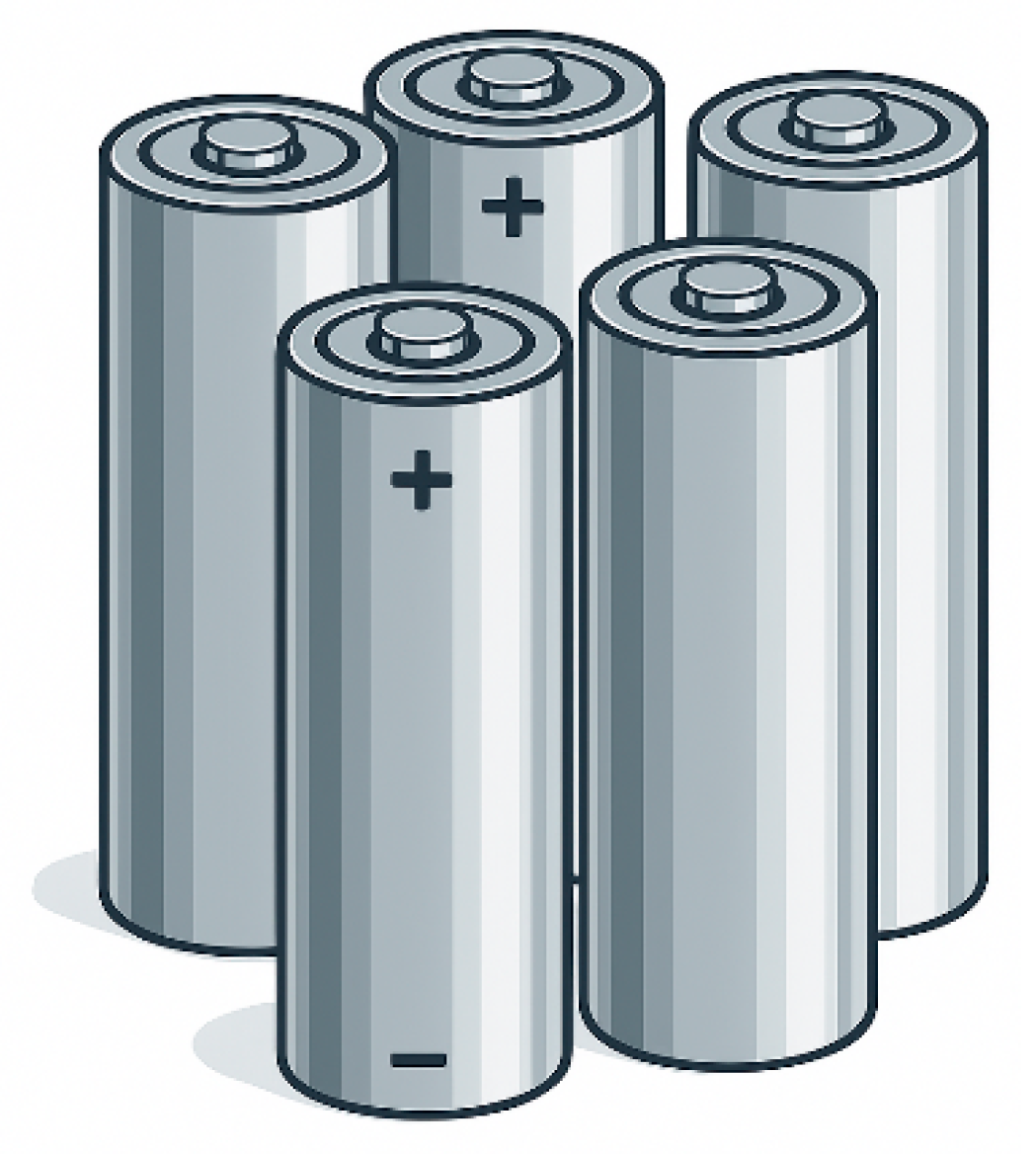
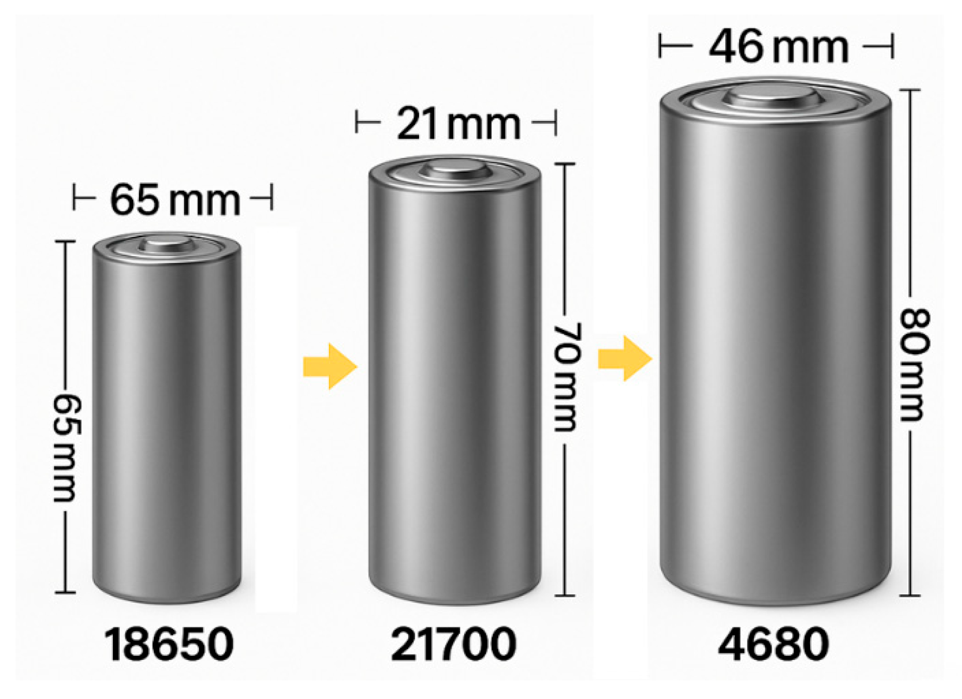
Cylindrical lithium-ion cells have become one of the defining components of modern battery electric vehicles, valued for their high energy density, reliability, thermal stability, and manufacturing maturity [45]. Figure 7 is a pictorial view of a cylindrical cell; it got its name from the shape. They are made of three standard form factors: 18650, 2170, and the newly introduced 4680. They differ mainly in diameter, length, and capacity, but share key advantages that have driven their widespread adoption among automakers [46]
  • 18650 Cells
  • 18650 Cell is 18 mm in diameter and 65 mm in length. Each cell typically weighs 45–48 g and can store up to 3000–3500 mAh (equivalent to 3.0–3.5 Ah) of charge [47]. Its nominal voltage is 3.7 V; this means that the 18650 contains roughly 11–13 Wh of energy [48]. Early EV models of 18650 cells have about 240–250 Wh/kg (Energy Density). This type of cylindrical cells pioneered Tesla EV models—the 2008 Tesla Roadster and Model S/X packs each contained thousands of 18650 cells [49]. The Model S 85 kWh battery pack contains about 7000 18650 cells arranged in parallel/series, and assembled into modules [50,51].
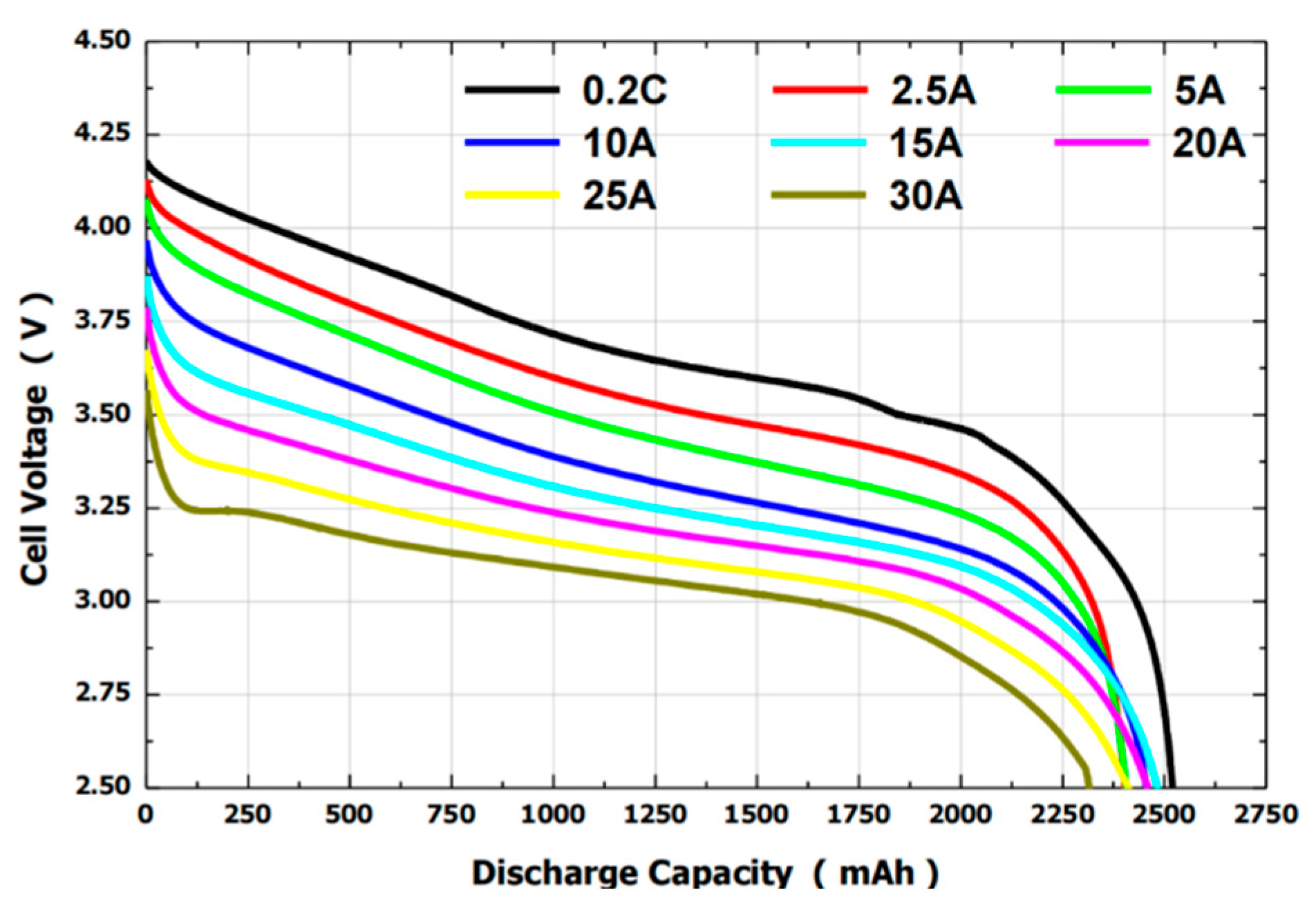
    The plots in Figure 8 show typical discharging characteristics of a 18650 lithium-ion cell at various constant currents. As discharge current increases from 0.2 to 30 A, voltage drops faster, and capacity decreases. Higher currents cause greater internal resistance effects, reducing the usable capacity and cell terminal voltage.
    Figure 8. Discharge Characteristics of 18650 Cylindrical Lithium-Ion Cells, Reprinted with permission from [48].
    Figure 8. Discharge Characteristics of 18650 Cylindrical Lithium-Ion Cells, Reprinted with permission from [48].
    Wevj 16 00573 g008
  • 2170 (21700) Cell
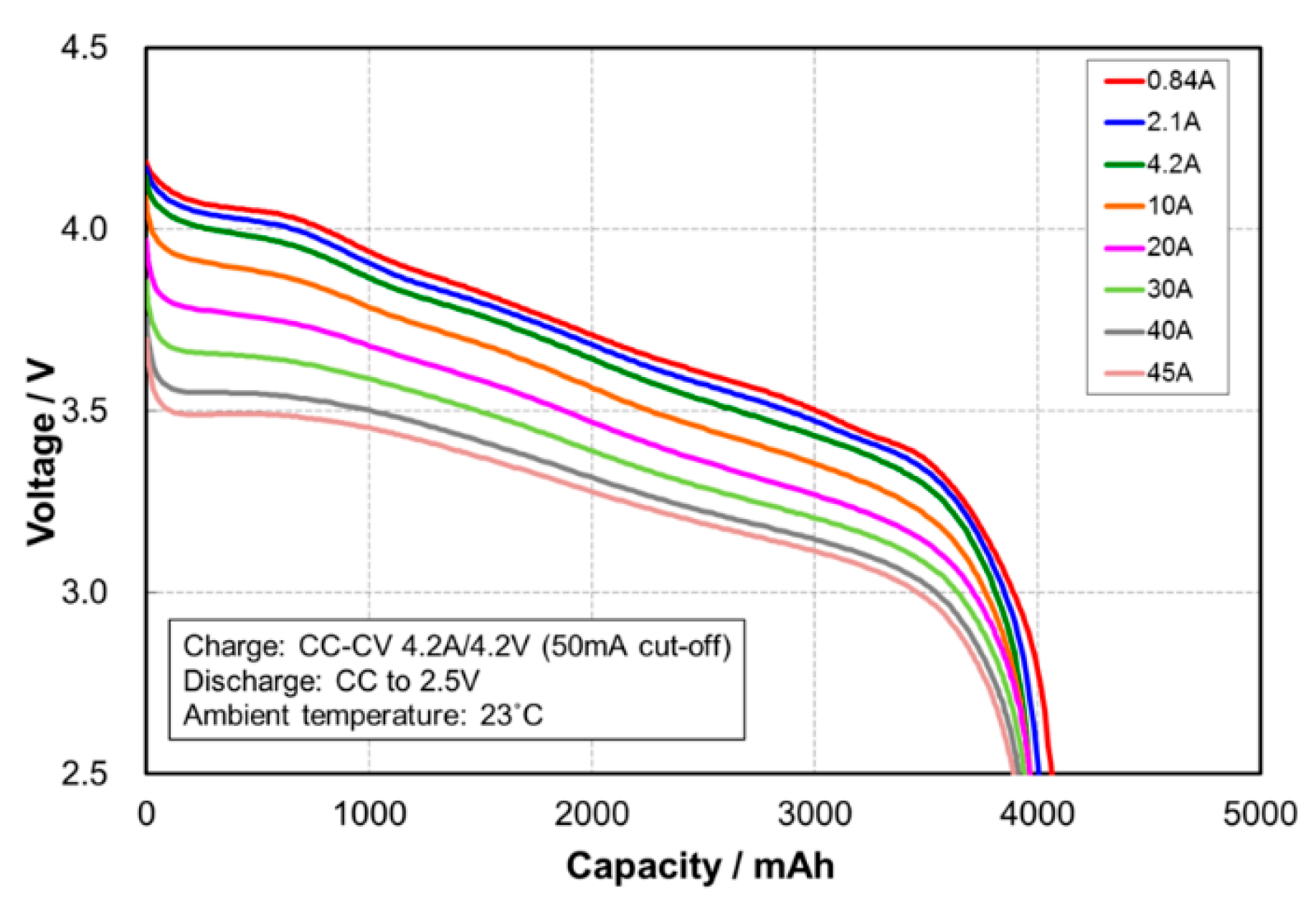
  • The 2170 (21700) Cell has dimensions of 21 mm in diameter and 70 mm in length. Typical EV 2170 cell is around 4.5–5.0 Ah each, which is about (4800–5000 mAh) [49,52], with energy density of 260–300 Wh/kg [53]. Figure 9 is the discharge characteristic plot for 2170 lithium-ion cells for voltage versus capacity at different constant current rates (0.84 A to 45 A). Higher discharge rates lead to lower operating voltages and reduced usable capacity [52]. Each 2170 cell holds more energy than a 18650, so an EV pack can use fewer cells to achieve the same capacity.
    Figure 9. Discharge Characteristics of 2170 Cylindrical Lithium-Ion Cells, Lithium-Ion Cells, Reprinted with permission from [52].
    Figure 9. Discharge Characteristics of 2170 Cylindrical Lithium-Ion Cells, Lithium-Ion Cells, Reprinted with permission from [52].
    Wevj 16 00573 g009
  • 4680 Cell
  • The 4680 Cell has a 46 mm diameter and 80 mm length. This format was unveiled by Tesla at Battery Day 2020; it is larger in volume than that of the 2170 cell. Each 4680 cell can store up to 25 Ah of charge, equivalent to 96–99 Wh per cell, which is five times the energy capacity of 18650 Cells [54]. Tesla’s first 4680 cells were made of a high-nickel NCM811 cathode, achieving 272–296 Wh/kg [55].
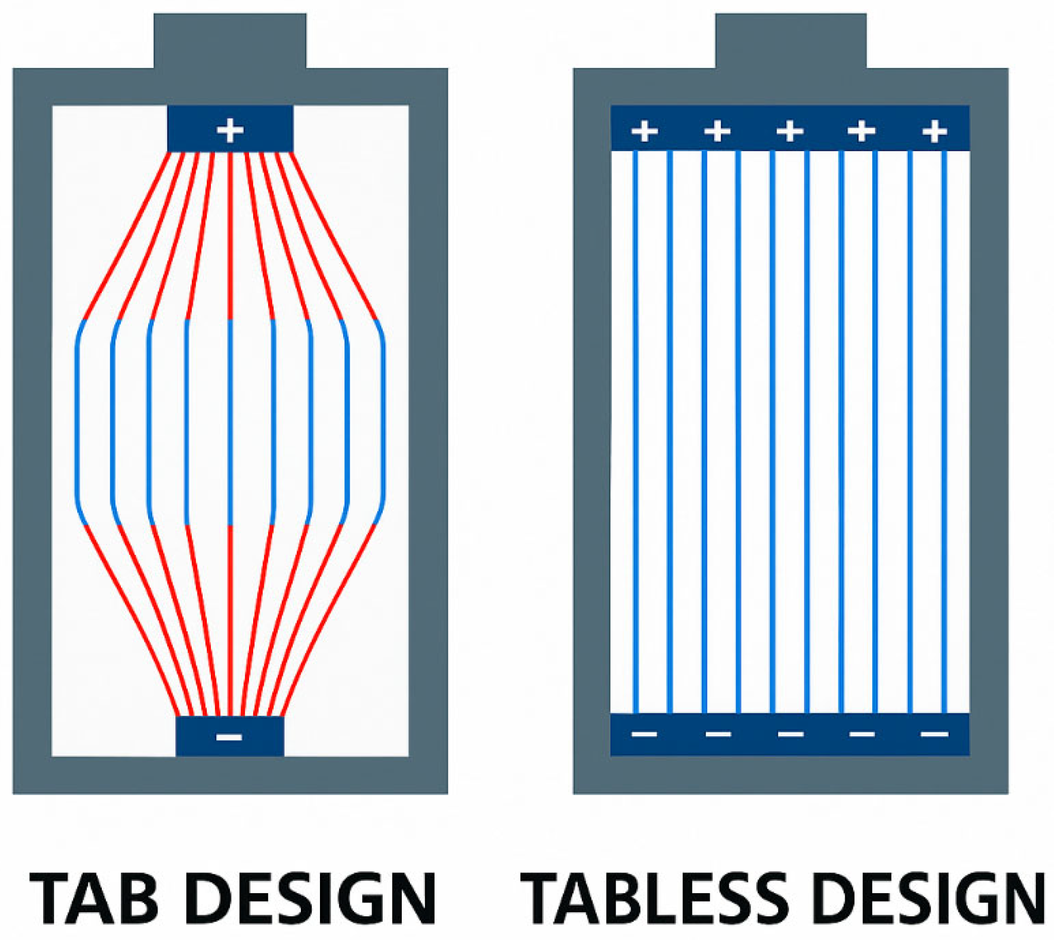
Thermal Properties of 4680: Scaling up a cylindrical cell presents thermal management challenges—larger cells generate more heat and are harder to cool uniformly. Tesla addressed this by introducing a “Tabless Electrode Design” in the 4680, which uses a shingled spiral wound electrode that acts like many tiny current tabs along the electrode sheet [56]. This innovation reduces internal resistance and distributes current and heat uniformly across the electrodes, allowing a larger cell to maintain good thermal performance. The 4680’s tabless design enables rapid heat conduction out of the core of the cell, preventing hotspots [56]. This can be seen in Figure 10.
Form Factor Differences: The jump from 21 mm to 46 mm diameter fundamentally changes the module/pack design [57]. A single 4680 cell holds more energy than the older 2170 cells. This simplifies wiring and module assembly; fewer cells and fewer connections [58]. However, the cells’ large size means fewer parallel paths in the pack, so each cell carries more current, making the tabless design to have high thermal conduction with high power output [55]. In Tesla’s newer models, the new form factor alone yields a 16% increase in vehicle range and a 14% reduction in $/kWh cost at the cell level [58].
Figure 11 and Table 1. Compare cylindrical lithium-ion battery cells: 18650, 21700, and 4680. We can see the dimensions of the 18650 measure 18 mm in diameter and 65 mm in height, and it is widely used in laptops and power tools. The 21700 cylindrical cells, measuring 21 mm by 70 mm, offer higher energy density and are used in EVs like Tesla. The new 4680 cylindrical cell, measuring 46 mm by 80 mm, promises greater capacity, improved thermal performance, and better manufacturing efficiency for electric vehicles.
  • Recent and Future Developments in Cylindrical Cell Technology
  • Cylindrical cell batteries are undergoing transformations that will boost their performance and extend their range of applications. Tabless designs integrate continuous current collectors directly on the electrode, shortening current paths, improving electrical uniformity, enhancing thermal management, and boosting rate capability, energy efficiency, and power density [60]. Below are the recent trends in cylindrical cell developments.
  • Cylindrical Cell Tabless and Advanced Internal Designs
The tabless concept was introduced in Tesla’s 4680, creative internal engineering for cylindrical cells [61]. By eliminating the traditional single current tab and instead connecting the electrode sheets along their entire edge, Tesla reduced internal resistance and heat generation dramatically. This innovation enables larger cylinders to charge and discharge faster without hotspots [61]. In the future, variations like multi-tab or foil-based current collectors in cylindrical cells from other manufacturers will be available. CATL is already working on a dual-tab design for its 46 mm cells [62]. Additionally, new electrode configurations—such as “jelly rolls” with novel stacking or folding patterns are being explored to further reduce resistance and increase energy density [63]. This will also facilitate even faster charging; with better internal current pathways, large cylindrical cells can intake higher currents with less heat [61]. The 4680 supports higher charge rates than earlier cells, and future designs will enhance it further. Figure 12 shows the designs for tab and tabless cells.
2.
Cylindrical Cell Structural Integration into Vehicles
Tesla’s recent models make use of the 4680 cells as a structural element—essentially turning the battery pack into part of the car’s frame, as can be seen in Figure 13 [64]. This approach eliminates the need for many steel supports, reducing weight, helping with ride, and handling. Future BEV platforms may incorporate cell-to-chassis designs, whether with cylindrical cells or prismatic cells [65]. Going forward, there are going to be refinements like foam fillers or polymer adhesives that securely hold cells while also acting as thermal interface and vibration damping. The concept of “cell as structure” could yield lighter and safer EVs [64]. Companies like BMW will soon start using their new cylindrical cells in a pack that is an integral part of the vehicle floor (BMW noted a 50% pack cost reduction partly via new pack design) [66].
3.
Solid-State and New Chemistries in Cylindrical Format.
A conventional cylindrical battery cell can be redesigned into a solid-state cell, where both the electrodes and the electrolyte are entirely solid. Solid-state batteries represent the next major leap in battery technology. Instead of using a liquid electrolyte, they employ a solid electrolyte, which allows the integration of lithium metal anodes. This innovation delivers significantly higher energy density, improved safety, and better thermal management, making it one of the most promising directions for future energy storage systems [68]. While solid-state cells remove flammable liquid electrolytes and may enable lithium-metal anodes, long-term cycling durability is not yet proven at practical loadings and rates. Reliable operation requires lithium to strip/plate densely without filament growth, which is constrained by an interface-specific critical current density and by chemo-mechanical stability at the Li electrolyte interface. From the literature, stress-assisted lithium penetration and electrolyte fracture cycle life remain an active challenge [69,70]. Likewise, safety is not inherently guaranteed: cell-level behavior depends on the solid-electrolyte family like sulfide, oxide, and polymer, cathode composition/voltage, interfacial reactivity, stack pressure, and cell format; sulfides can evolve H2S upon moisture exposure, oxides can be brittle, and thermal-runaway pathways have been observed in certain solid-state battery configurations [70,71].
So far, most solid-state battery development has focused on prismatic and pouch formats, partly because some solid-state designs involve stacking flat layers [68]. Another area of battery chemistry evolution is high-silicon or even lithium metal anodes in a liquid-electrolyte cell [72]. Future cylindrical cells could incorporate silicon or other additives to boost capacity [68]. Likewise, moving to cobalt-free high-nickel cathodes like NCMA or even lithium-rich manganese could increase energy density. As these chemistries mature, cylindrical casing will be adapted to contain them. One advantage of cylindrical cells is that their casing can better handle internal pressure changes and keep the cell intact even if new chemistries cause more expansion or gas generation [63]. This could become useful if solid-state or other chemistries have challenging swelling behavior. The cylindrical cells might withstand those stresses better than a large flat pouch.
4.
Cylindrical Cell Enhanced Thermal Management Techniques.
As cylindrical cells get larger and pack energy rises, new cooling strategies in battery electric vehicles are emerging, shown in Figure 14. Tesla’s current approach uses cooling tubes or plates [58] that contact the cell’s curved surface about mid-height, but future packs might use more enveloping cooling. One concept is immersion cooling—submerging cells or modules of cells in a dielectric coolant that circulates to remove heat directly from the cell surface [73]. Some racing EVs or experimental packs have done this with cylindrical cells. It can dramatically increase heat rejection and allow ultra-fast charging without overheating. Companies may also experiment with radial cooling, like cooling channels that go into the hollow core of a jellyroll; some large cells have a small hole or could be built with a cooling channel down the center [59].
Another idea is using the cell itself as a cooling channel by flowing coolant through a jacket that doubles as the cell casing. The 4680 structural pack uses a cooling snake that weaves between cells, contacting each other. Better thermal management will be crucial if we want higher charging speeds—say charging an EV in 10 min [59]. Large cylindrical cells could potentially take very high currents if kept cool, so effective cooling techniques are very important. We might also see temperature control at the cell level: e.g., integrating thermal foils or heat spreaders around each cell to quickly distribute any hot spots [73]. All of those aim to ensure even large cylindrical cells operate safely and efficiently under extreme conditions.
  • Automakers and BEV Models Using Cylindrical Cells
Cylindrical cells in EVs were popularized by Tesla and have since been adopted by several other automakers. Below are some notable examples of automotive companies and specific EV models, past and present, that use cylindrical battery cells.
Tesla Inc.: Tesla is the most prominent user of cylindrical cells. All of Tesla’s production models to date have employed cylindrical lithium-ion batteries [55]. Tesla Roadster (2008)—The original Roadster was the first production EV to use thousands of laptop-style 18650 cells as its sole energy source. Its battery pack contained 6831 Panasonic 18650 cells (NCR18650 cells of 2.4 Ah each at the time) to store about 53 kWh. This unprecedented design proved that cylindrical cells could power a full-size EV [49].
Lucid Motors: The Lucid Air uses 2170 cylindrical cells, sourced from LG Chem (LG Energy Solution). In 2020, LG Chem announced it would be the exclusive supplier of 21700 cells for the Lucid Air’s initial versions (from late 2020 through 2023) [74].
Rivian: Rivian Automotive, known for its R1T electric pickup and R1S SUV, also adopted 2170 cylindrical cells. Rivian partnered with Samsung SDI to supply these cells. The R1T’s battery pack (135 kWh in the “Large pack”) uses thousands of 21700 NCA cells from Samsung, arranged in modules and immersed in a cooling interface [30].
  • Advantages of Cylindrical Cells
Mature, Standardized Design: There are universal size standards (18650, 21700, and 4680) followed by many manufacturers, which means automakers can source cells from multiple suppliers and leverage economies of scale.
Structural Robustness and Safety: The cylindrical shape is inherently strong and can tolerate internal pressure without deforming. As a cell ages or experiences stress, it generates gas; the cell’s round metal casing can withstand this pressure more than a rectangular cell would [60].
Thermal Management: Cylindrical cell packs naturally provide space for cooling between cells, enhancing heat dissipation [73]. Air or coolant can circulate around each cell’s curved surface, contributing to temperature uniformity [59].
Manufacturing Yield and Cost: Recent developments have made it possible for cylindrical cells to be highly manufacturable on automated lines at high speeds. Cylindrical cells have traditionally been one of the cheapest formats per kWh to produce [75].
Volumetric efficiency: Round cells do not tessellate; casing and inter-cell gaps lower pack Wh/L versus prismatic blocks.
  • Disadvantages of Cylindrical Cells
Inactive mass: Metal casing, cap/vent, and gaskets add non-active weight, reducing Wh/kg.
Interconnect complexity: Thousands of welds, fuses, and sense lines increase cost and potential failure points.
Thermal challenges: Heat must conduct from the jelly-roll core; high C-rates create core hot spots and non-uniformity across large arrays.
Propagation risk: A vent/runaway cell can impinge on neighbors; mitigation (potting/barriers) adds mass and volume.
Variability and balancing: More cells increase dispersion; BMS balancing/diagnostics overhead grows.
Packaging constraints: Fixed diameters/heights limit geometric freedom; skateboard floor thickness and tapered regions pack poorly.
Scaling to larger formats (e.g., 4680): Radial cooling, mechanical expansion, and formation throughput are harder; advantages depend on the tabless current collection and manufacturing yield.

2.1.2. Prismatic Cells

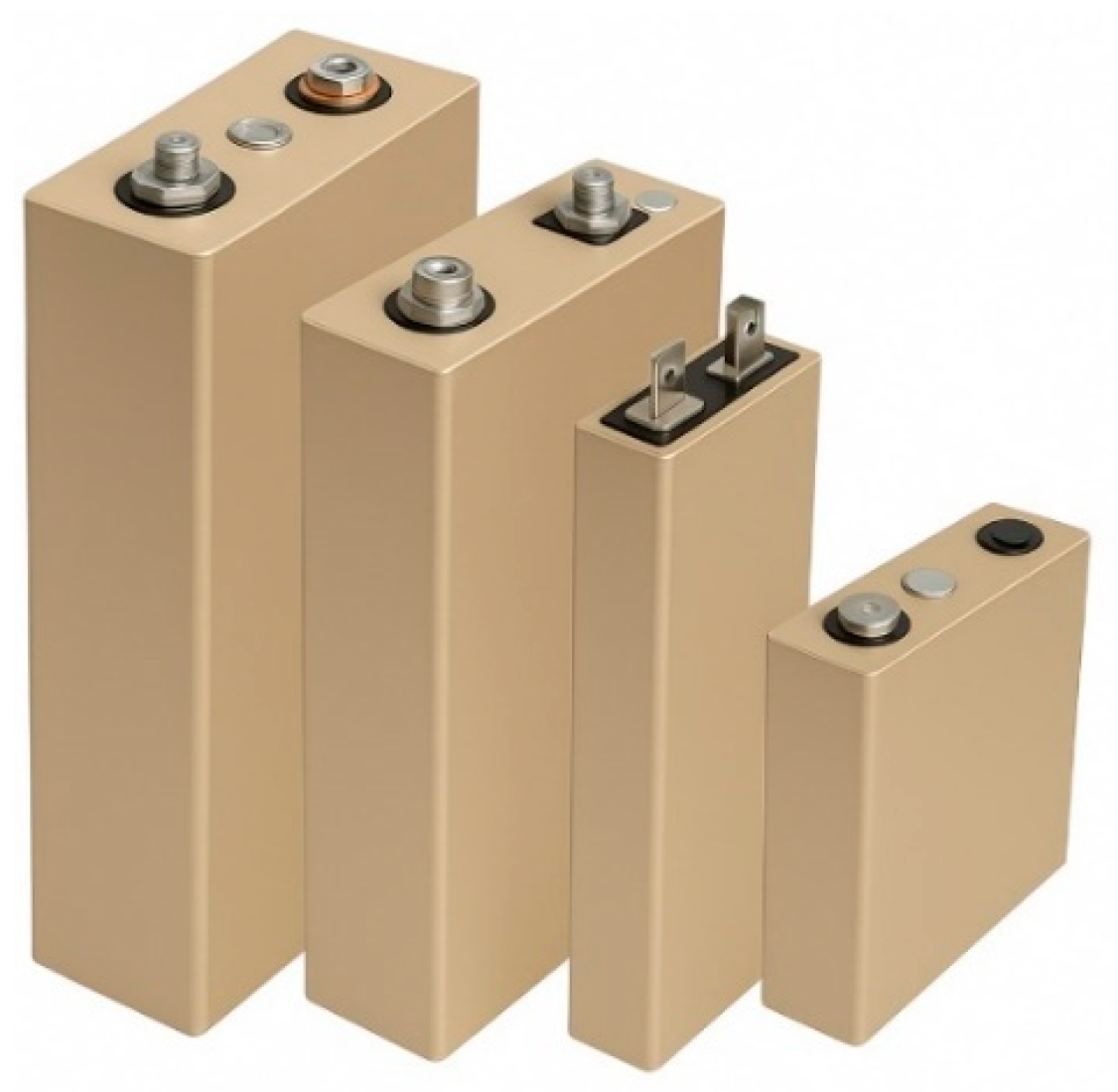
Prismatic cells are rectangular or square lithium-ion cells encased in a rigid housing, often aluminum or steel. They can be much larger than cylindrical cells—a single prismatic cell may have dimensions on the order of tens of centimeters. For example, BYD’s “Blade” LFP prismatic cell is about 960 mm long, 90 mm wide, and only 13.5 mm thick, with a capacity of 138 Ah [76]. Prismatic EV cells commonly range from 50 Ah to 200 Ah per cell, significantly larger capacities than cylindrical cells. Because of their large size, fewer prismatic cells are needed to build a battery pack. Figure 15. Shows four different sizes of prismatic lithium-ion battery cells with metallic terminals.
  • Internal Design—Stacked vs. Wound Prismatic Cell
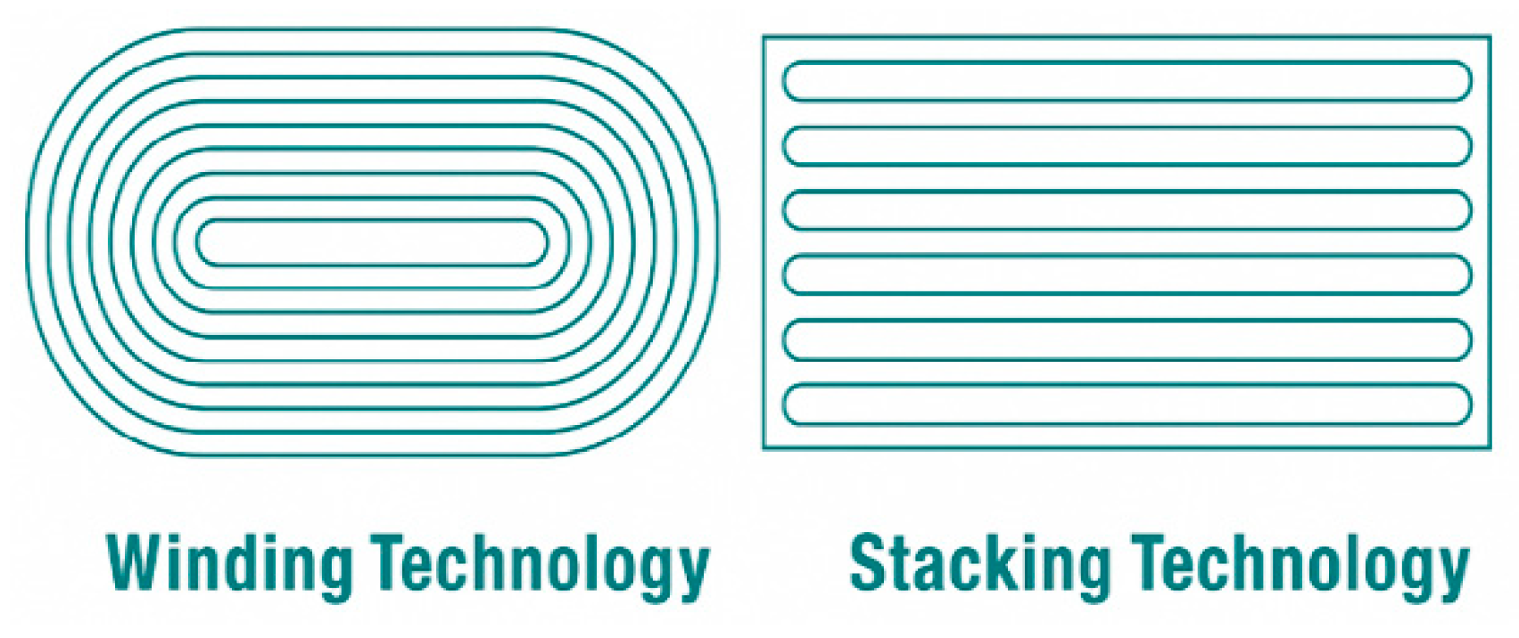
Inside a prismatic cell, the positive and negative electrode layers can be arranged in two main ways: wound jelly roll or stacked laminated [77].
In wound prismatic cells, long electrode sheets are wound in an oval jellyroll and then flattened into a rectangular casing. This method is traditional and cost-effective, but it leaves an empty gap in the cell and can create stress at the curved edges [77].
The prismatic cells are built by putting together many flat electrode sheets like a deck of cards stacked in a Z-fold shape, as shown in Figure 16, then inserting the stack into the rectangular casing [77,78].
Stacked designs maximize internal space utilization and maintain uniform pressure on the electrodes. This yields higher volumetric energy density and more uniform mechanical stress distribution than wound designs [79]. A well-engineered stacked prismatic cell can endure thousands of cycles with minimal deformation. The trade-off is that stacking electrodes is more complex and slower in manufacturing than winding.
  • Energy Density of Prismatic Cell
Modern prismatic cells can achieve competitive energy densities. High-nickel chemistry prismatic cells, e.g., NMC 811 cathode, have about 250–270 Wh/kg at the cell level and 600 Wh/L in volume [80]. For instance, CATL’s NMC811 prismatic cells made in 2019 have around 270 Wh/kg and 660 Wh/L cell-level [81], and prismatic NCA cells used by Tesla/Panasonic are also in a similar range.
Generally, prismatic cells offer high volumetric efficiency and can be optimized for either energy density or power, depending on design. Automakers often choose prismatic formats for space-constrained pack designs where maximizing kWh within a given volume is critical [82].
  • Key Manufacturers of Prismatic Cells
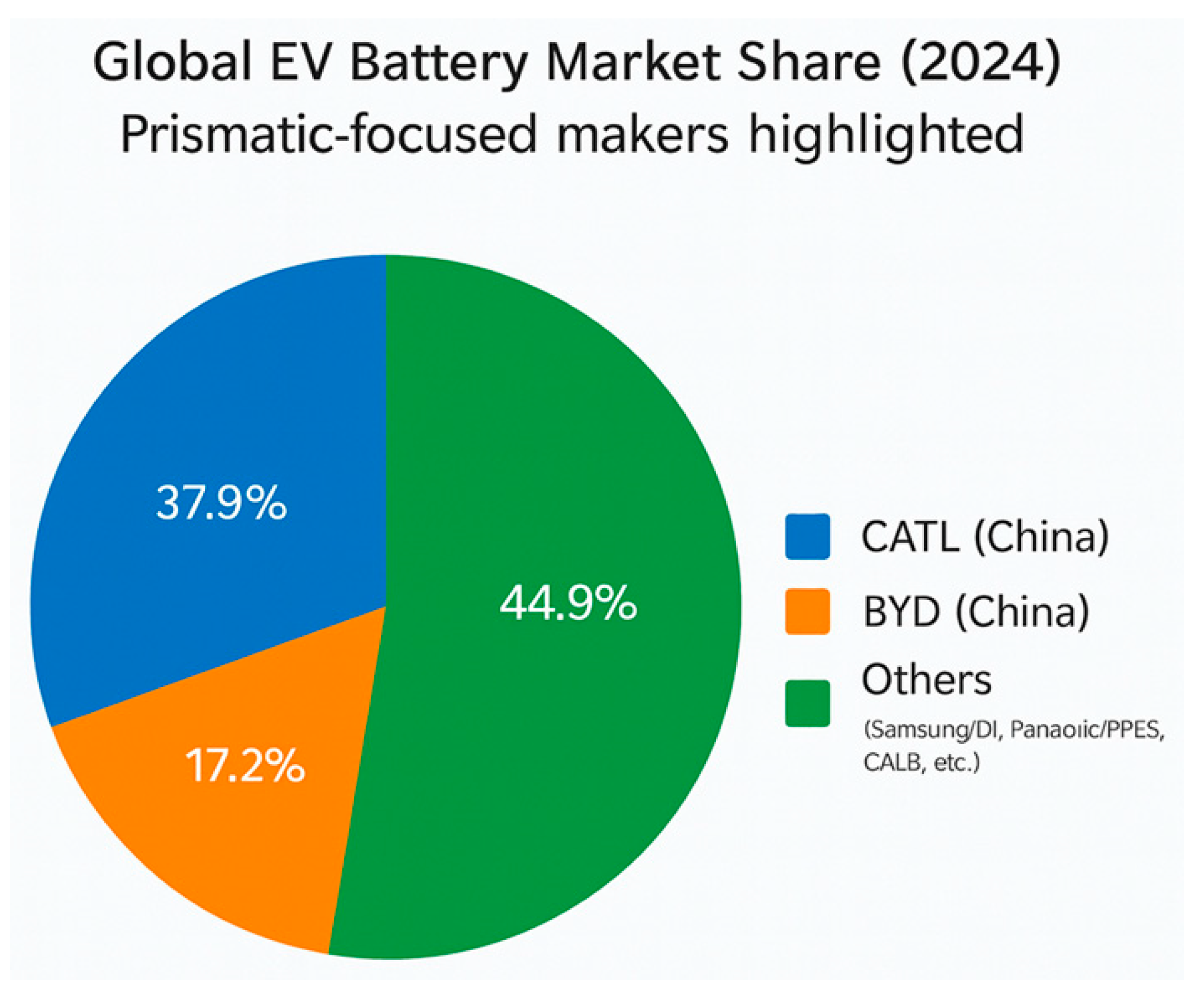
The global EV battery industry is dominated by a handful of large companies, many of which produce prismatic cells especially for high-volume automotive use. The global market share is shown in Figure 17. The global market share of each of the companies is discussed here
CATL (China): 37.9% 2024 share [83]; prismatic LFP and high-Ni NMC/NCA; supplies Tesla, VW, BMW, Mercedes, Honda; ~50–280 Ah offerings [84,85].
BYD (China): 17.2% 2024 share [83]; Blade Battery—long, thin LFP prismatic (≈0.9 × 0.10 × 0.013 m) emphasizing safety and longevity.
Samsung SDI (Korea): Long-time prismatic supplier (e.g., BMW i3 120 Ah) [86]; high-performance NMC/NCA with aluminum casing; prototyping prismatic solid-state cells [87,88,89].
Panasonic and Toyota PPES (Japan): JV producing prismatic cells for Toyota HEV/BEV; strategy prioritizes durability (≥10-year service) [90].
CALB (China): Top Chinese producer (7th globally in 2023) [91]; prismatic LFP/NMC (e.g., 50/100 Ah) for GAC [88].
Generally, China (CATL, BYD, CALB) leads in prismatic/LFP; Korean and Japanese firms also focus on high-performance prismatic cells. North America and European automakers are forming local joint ventures as prismatic becomes a preferred next-gen format [89].
  • Automakers and BEV Models Using Prismatic Cells
Many automakers have adopted prismatic cells in their battery packs, especially in recent years, as prismatic formats have become more prevalent. This can be shown in Figure 18. Below are some notable examples of automakers that use prismatic cells in production EVs.
Volkswagen Group (VW, Audi, Porsche, etc.): VW has been a major proponent of prismatic cells. Volkswagen ID.3 and ID.4 models use Samsung SDI and CATL prismatic cells [26,90]. Models across VW, Audi, and Skoda are transitioning into the standardized prismatic cells [91]. Overall, VW Group is moving away from pouch (LG, SK) to prismatic, which is a landmark in the industry, influencing suppliers and other automakers [91].
Toyota: Toyota has consistently used prismatic battery cells across its vehicle platforms—from NiMH in the Prius to lithium-ion in BEVs like the bZ4X and C-HR/IZOA EV [3]. Toyota’s roadmap includes high-nickel and LFP prismatic batteries, as well as solid-state prototypes in prismatic form, highlighting its long-term commitment to this cell format and partnerships with suppliers like CATL and BYD [92].
BMW: BMW was among the first automakers to adopt prismatic lithium-ion cells in modern electric vehicles, starting with the BMW i3, which used Samsung SDI prismatic NMC cells.
BYD (and other Chinese automakers): BYD uses its own prismatic LFP cells in all its electric models. The BYD Han sedan, Tang SUV, Atto 3 (Yuan Plus), Dolphin, etc., all contain variants of the Blade prismatic cell or related prismatic designs [93]. Nearly every Chinese automaker is using LFP prismatic cells; this is because CATL, BYD, and CALB only supply prismatic LFP [31].
Tesla: Tesla is famously loyal to cylindrical cells (18650 in Model S/X, then 2170 in Model 3/Y) [81,94]. However, Tesla made a significant change for its Standard Range models starting in 2020–2021; the Model 3 Standard Range and later Model Y Standard Range made in China use CATL’s prismatic LFP cells [95].
General Motors (GM): GM’s current Ultium platform uses LG-supplied pouch cells, but the company is shifting toward prismatic formats. In 2023, GM partnered with Samsung SDI to supply high-nickel prismatic NCA cells from 2026 onward [96]. Future GM EVs may adopt prismatic modules for improved energy density, simplified pack design, and manufacturing efficiency [97,98].
Mercedes-Benz: Mercedes has taken a diversified approach to their EV cars. Some Mercedes EVs use prismatic cells, others pouch cells, depending on the supplier and model. Benz is now increasingly aligned with the prismatic format as well, after some early reliance on pouch.
Stellantis (Fiat/Chrysler/Peugeot Brands): Stellantis vehicles have used a mix: the European Peugeot e-208 and Opel Corsa EV use CATL prismatic cells (50 kWh pack LFP in newer versions). Some Jeep and Fiat EVs in China use prismatic. Stellantis has two battery JVs for Europe and another with Samsung SDI in the US [99].
  • Future Developments and Innovations in Prismatic Cell Technology
Looking ahead, prismatic cell technology and its usage in EVs are poised for further evolution. Key recent developments include.
Cell-to-Pack (CTP) and Structural Integration: The move to eliminate discrete modules and integrate cells directly into the pack is accelerating. Prismatic cells are central to this trend. CATL’s third-generation CTP 3.0 “Qilin” battery is a showcase: prismatic cells are directly bonded with a multi-functional elastic cooling plate between them, and the pack achieves record integration level 72% volume efficiency [100].
BYD’s Blade pack, similarly, is a CTP design where the long prismatic cells form a honeycomb-like structural pack, as shown in Figure 19 We will see more automakers designing chassis and crash structures around prismatic cells, often referred to as cell-to-chassis or cell-to-body designs [93]. This structural battery approach can reduce vehicle weight and increase stiffness [93]. Tesla’s use of a structural pack with cylindrical cells demonstrated up to 10% mass reduction; similar gains are expected when applying the concept to prismatic systems [57]. In China, startups like Leapmotor have introduced “CTC” (cell-to-chassis) EVs using prismatic cells directly integrated into the vehicle frame [101].
Unified Cell Formats and Standardization: Volkswagen’s unified prismatic cell, scheduled for 2025 production, will create a one-size-fits-all cell for electric vehicles [102]. The unified cell is prismatic and is designed to accommodate various chemistries (LFP, low-cobalt NCM, high-nickel NCMA, and even solid-state in the future) all within the same physical package. This could simplify manufacturing and allow VW to flexibly switch chemistries without redesigning packs. It is likely we will see other automakers push for some standard prismatic cell dimensions, especially in China, where CATL and others could set industry standards [103].
Solid-State Batteries in Prismatic Format: Most SSB developers are using either prismatic or pouch form factors for prototype cells—largely because solid electrolytes are typically formed as flat sheets [104,105,106]. QuantumScape, a prominent solid-state startup, produces 100-layer cell prototypes in a flat format (akin to a prismatic sub-cell) and has indicated that cylindrical shapes are not suitable for lithium-metal anodes due to stress from expansion [107].
This suggests that the majority of the first-generation solid-state EV batteries will likely be prismatic or pouch. When solid-state achieves commercial viability, prismatic formats with their standardized casings and ability to handle cell swelling from external compression will be among the first deployed in mass-produced EVs.
Higher Integration and “Blade” Concepts: Inspired by BYD’s Blade, other companies are innovating on cell shapes and integration [93]. CATL is working on a “Blade-like” LFP cell (long and thin) for certain vehicle platforms to enable a very low-profile pack (important for vehicle interior space) [100].
New Chemistries in Prismatic Cells: The industry is also exploring new cathode chemistries, low or no nickel, such as manganese-rich or lithium iron manganese phosphate (LMFP). and even anode innovations (silicon anodes) to boost energy density [108]. These can be implemented in any format, but prismatic cells offer the flexibility of a large size needed for lower-energy chemistries like LMFP and sodium-ion, while still achieving usable pack density [6,108]. CATL is developing sodium-ion batteries and plans to use a prismatic format for them due to sodium-ion’s lower Wh/kg; large, prismatic cells will be used to hit pack-level targets [109]. We also see 4680 cylindrical focusing on high-nickel, whereas LFP/LMFP likely stay prismatic [56]. Prismatic cells will remain the preferred choice for robust, cost-effective chemistries—particularly those that emphasize long cycle life and safety rather than maximizing energy density by weight.
Fast Charging and Thermal Improvements: Prismatic cell designs are improving fast charging—e.g., CATL’s new Shenxing prismatic LFP cells claim 4C fast-charge capability, 10 min to 80% with special electrolyte and thinner electrodes [62]. Some designs have embedded thermal conductive materials or novel tab arrangements like “bi-polar” electrode to reduce resistance and heat.
We may see prismatic cells with internal cooling features, like micro cooling channels or heat fins, as part of the cell casing [110]. Another emerging idea is smart prismatic cells with built-in sensors like temperature and pressure sensors for each cell to improve battery management [111].
  • Advantages/Disadvantages of Prismatic Cells
Prismatic cells bridge the gap between cylindrical cells and pouch cells. Below is a comparison of key factors—pack efficiency, thermal management, manufacturing, and safety, highlighting prismatic pros and cons relative to cylindrical and pouch formats.
Packing Efficiency: The rectangular shape allows the cee to fill a battery pack with minimal empty space. Unlike cylindrical cells, which leave gaps when packed in an array, prismatic cells can be stacked with very high packing density [112].
Thermal Management: Prismatic cells are much larger, and when packed tightly together, there is less open space for coolant flow. Cooling for prismatic cells is often done via thermal interface plates or cooling channels at the cell bottoms or sides [113]. Overall, cylindrical packs tend to have an easier time with cooling airflow, whereas prismatic/pouch packs rely on engineered cooling plates and good design to maintain even cell temperatures. With proper pack design, prismatic systems can achieve excellent thermal performance [114].
Manufacturing and Design Complexity: Cylindrical cells have been produced for decades (18650 cells were standardized in the 1990s) and enjoy extremely mature, cost-effective manufacturing [115,116]. Fewer connections mean fewer potential failure points and faster pack assembly—this is a major prismatic advantage in manufacturing and reliability [112]. Prismatic cells come in a self-supporting rigid casing, so module structure can be simpler or modules can even be eliminated in cell-to-pack designs [117].
Mechanical safety: Prismatic cell casings are strong and generally more resistant to external shocks or deformation than soft pouch cells. They are less likely to be punctured in an accident compared to pouches, which is why many automakers prefer prismatic over pouch, despite slight weight penalties [117]. One other advantage of prismatic formats is the lower number of cells in a pack; fewer cells mean fewer points of failure in terms of cell defect probability and simpler BMS monitoring [110]. But it also means that if one cell fails, a larger fraction of the pack’s capacity is affected; each prismatic cell is “single string” in series in many designs.

2.1.3. Pouch Cells

A pouch cell is a flat, rectangular lithium-ion cell in a sealed flexible foil package, typically laminated with aluminum-polymer instead of a rigid casing [118].
Internally, the electrodes and separators are either stacked or wound flat and then enclosed in the pouch envelope. Unlike cylindrical or prismatic cells, pouch cells have no standardized dimensions—each manufacturer designs custom sizes for their applications [118]. Figure 20 depicts the outlook of pouch cells.
Typical EV pouch cells tend to be large in area and thin, as shown in Figure 20 above; for example, a 50 Ah NMC pouch cell may measure 320 mm × 102 mm. The nominal voltage per cell depends on chemistry; about 3.6–3.7 V for NMC/NCA, 3.2 V for LFP, and multiple pouch cells are usually connected in series and parallel to form modules and packs [119]. Pouch-format cells possess characteristics that make them particularly suitable for battery electric vehicles (BEVs). These include the following:
Packaging Characteristics: Pouch cells use heat-sealed flexible foils as the casing. This lightweight packaging yields extremely high packaging efficiency, about 90–95% of a pack’s volume can be active material. Unlike rigid metal-cased cells, they require external support to maintain shape and to compress the stack, especially as they swell slightly during charge-discharge cycles [120]. No metal casing means reduced weight; pouch cells weigh about 20% less than comparable aluminum-cased prismatic cells and 40% less than steel cylindrical cells for the same capacity [118]. However, the thin pouch is more susceptible to mechanical damage or puncture if not protected. Manufacturers often incorporate features like a temporary “gas bag” during formation to collect gases from initial solid electrolyte interface formation, which is later removed and the pouch resealed [121].
Capacity and Chemistries: Modern EV pouch cells commonly have capacities in the 40–100 Ah range per cell, much larger than cylindrical cells, which are usually 3–5 Ah each [122]. High-energy nickel-based chemistries like NMC, NMCA, or NCA cathodes with graphite/silicon anodes are commonly used in pouch formats for their energy density—for example, the 90 kWh Jaguar I-PACE battery uses 432 high-NMC pouch cells of 58 Ah each [123]. Pouch cells can also accommodate LFP (LiFePO4) chemistry, though LFP has more often been deployed in prismatic form factors by Chinese manufacturers.
There is no inherent chemistry limitation: both low-cobalt high-nickel chemistries and LFP can be implemented in pouches [124]. In practice, many North American and European electric vehicles (EVs) have utilized NMC-family pouch cells, while LFP pouch cells are less common, as LFP is predominantly used in prismatic form in China [124].
Solid-state/lithium-metal designs benefit from the flat layered structure, although managing the expansion of lithium metal in a pouch is a challenge being addressed with new cell designs [27,107,125].
  • Leading Pouch Cell Manufacturers and Technologies
From the global context as shown in Figure 17, the 2025 EV-battery market share is led by CATL (37.9%) and BYD (17.2%) [30,83]; both centered largely on prismatic/LFP cell format, while pouch cell format, which is majorly used by North American and European BEV automakers, is supplied by the following cell manufacturers:
LG Energy Solution (LGES): Large-format NMC/NCMA pouches (e.g., Ultium ≈ 100 Ah); GM and prior Bolt/Volt, I-PACE, early CN Model 3 [126,127,128].
SK On: Nickel-rich NCM 811 pouches for Hyundai Ioniq 5/6, Kia EV6, Ford F-150 Lightning/Mach-E; ≈80% in ~18 min fast-charge via electrode/thermal design [129].
AESC/Envision AESC: Leaf pioneer; Gen 5 NCM 811 ~230–250 Wh/kg, >300 Wh/L; Ariya (63/87 kWh); expanding UK, USA, France, and Japan [130].
Farasis Energy: High-Ni NMC pouches; Mercedes partnership; samples up to ~330 Wh/kg (semi-solid, high-Si anode) [126,127].
  • Automakers and EV Models Using Pouch Cells
Many leading automakers have utilized pouch cells in either current or past electric vehicles. Below is a rundown of notable examples and how pouch-cell choices have shaped these EVs.
Nissan: Nissan was an early pioneer in the use of pouch cells for their first-generation Nissan Leaf (2010). The Leaf’s battery packs (24 kWh, later 30 and 40, and 62 kWh options) all used AESC-manufactured NMC pouch cells [131]. Figure 21 shows the arrangement of the Nissan Leaf Pouch cell into a module, then into a pack. By 2028, Nissan will debut an all-solid-state EV from its Yokohama pilot line, employing laminated pouch cells leveraging AESC expertise [128]. From Leaf to Ariya, pouch cells remain integral to Nissan’s strategy as it explores new chemistries.
General Motors (GM): General Motors (GM) has been a pioneer in applying large-format pouch cells in its EVs for over a decade [129]. In 2010, GM’s Chevrolet Volt plug-in hybrid became one of the first modern EVs to deploy flat, high-energy-density pouch cells supplied by LG [132].
Ford has used pouch cells from LG and SK for most of its EVs up to 2025—the Mustang Mach-E uses LG pouch NCM cells, the F-150 Lightning uses SK pouch NCM [133]. The 2020 Mustang Mach-E employs LG Energy Solution’s NMC pouch cells in both Standard and Extended Range configurations [134,135]. Ford’s all-electric F-150 Lightning uses SK On-supplied NMC pouch cells, with either 384 or 560 high-capacity (150 Ah) cells depending on the chosen pack size, enabling towing, hauling, and rapid charging while fitting under the truck bed’s design constraints [135].
Hyundai Motor Group (Hyundai/Kia/Genesis): The Korean auto group has consistently used pouch cells in its EV and plug-in hybrid models, leveraging domestic suppliers LG and SK [136,137]. Early examples include the Hyundai Sonata PHEV and Kia Soul EV, first generation, which had pouch cells from SK Innovation.
Kia’s larger EV9 SUV (2023) continues with pouch NCM cells from SK, with options for standard (76 kWh) or long-range (100 kWh) packs. Hyundai has signaled it will also introduce LFP chemistry for standard-range models from 2024 onward, likely sourcing prismatic LFP cells from CATL for the Chinese market Kona EV and possibly globally for entry-level trims [138]. Hyundai and Kia have been strong proponents of pouch cells, balancing multiple suppliers (LG and SK) and benefiting from the format’s high energy in their stylish, space-efficient designs.
Other Automakers with Historical Pouch Cells: Other automakers that have used pouch cells include Jaguar Land Rover—the Jaguar I-PACE (2018) being a prime example with its 90 kWh LG pouch cell battery (and JLR’s plug-in hybrids also use LG pouch cells) [139]. Audi had the e-tron SUV (pouch cells) but moved on afterwards [140].
Generally, pouch cells have been favored by American automakers (GM, Ford) and some Asian automakers (Hyundai/Kia, Nissan) for their main EV lines, while European makers have been more mixed or leaning toward prismatic. Hyundai and Nissan remain committed to the pouch for current and next models.
In summary, on cell format types, each cell format has advantages and disadvantages: cylindrical handle heat well and are mechanically robust, prismatic simplify module assembly, and pouches offer high packaging efficiency. Automakers select formats based on their vehicle requirements and manufacturing strengths.

2.2. Battery Management System (BMS)

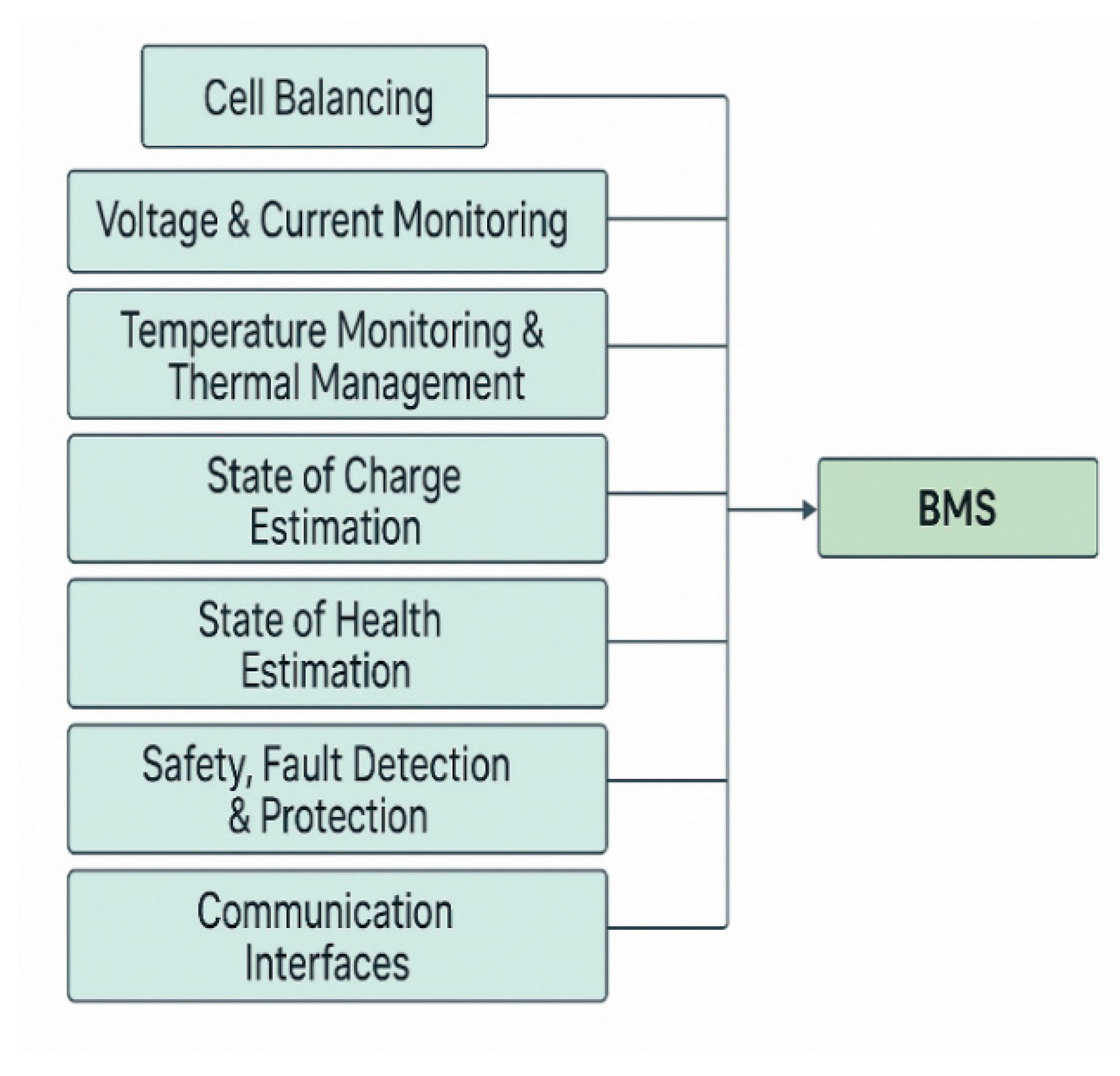
Electric vehicles (EVs) rely on large battery packs as their energy source, and ensuring these batteries operate safely and efficiently is critical. A Battery Management System (BMS) is an electronic control unit associated with sensors and software that serves as the “brain” of the battery pack [9]; the key functions of BMS are depicted in Figure 22. The BMS continuously monitors the battery’s condition, protects it from out-of-limit conditions, and optimizes its usage to extend life and performance. Modern EV BMS units are sophisticated, performing real-time analysis of each cell and coordinating with other vehicle systems [9,141].
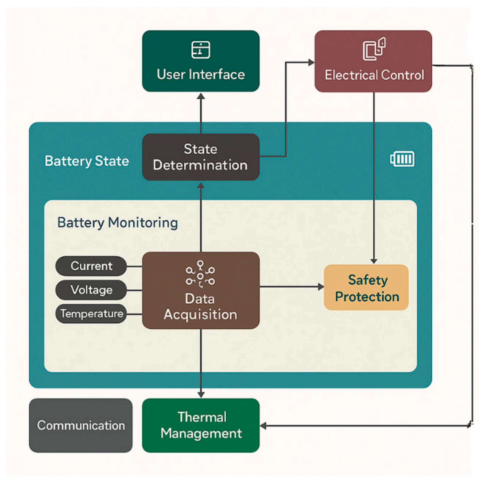
In essence, the BMS ensures the battery stays within safe operating parameters (voltage, temperature, current, etc.) and manages functions like balancing and state estimation, all while communicating with the vehicle’s control network, as shown in Figure 23.

2.2.1. BMS Functions and Critical Roles

BMS performs multiple critical functions to guarantee the battery pack’s safety, longevity, and reliable performance. Key roles of a BMS include the following:
Cell Balancing
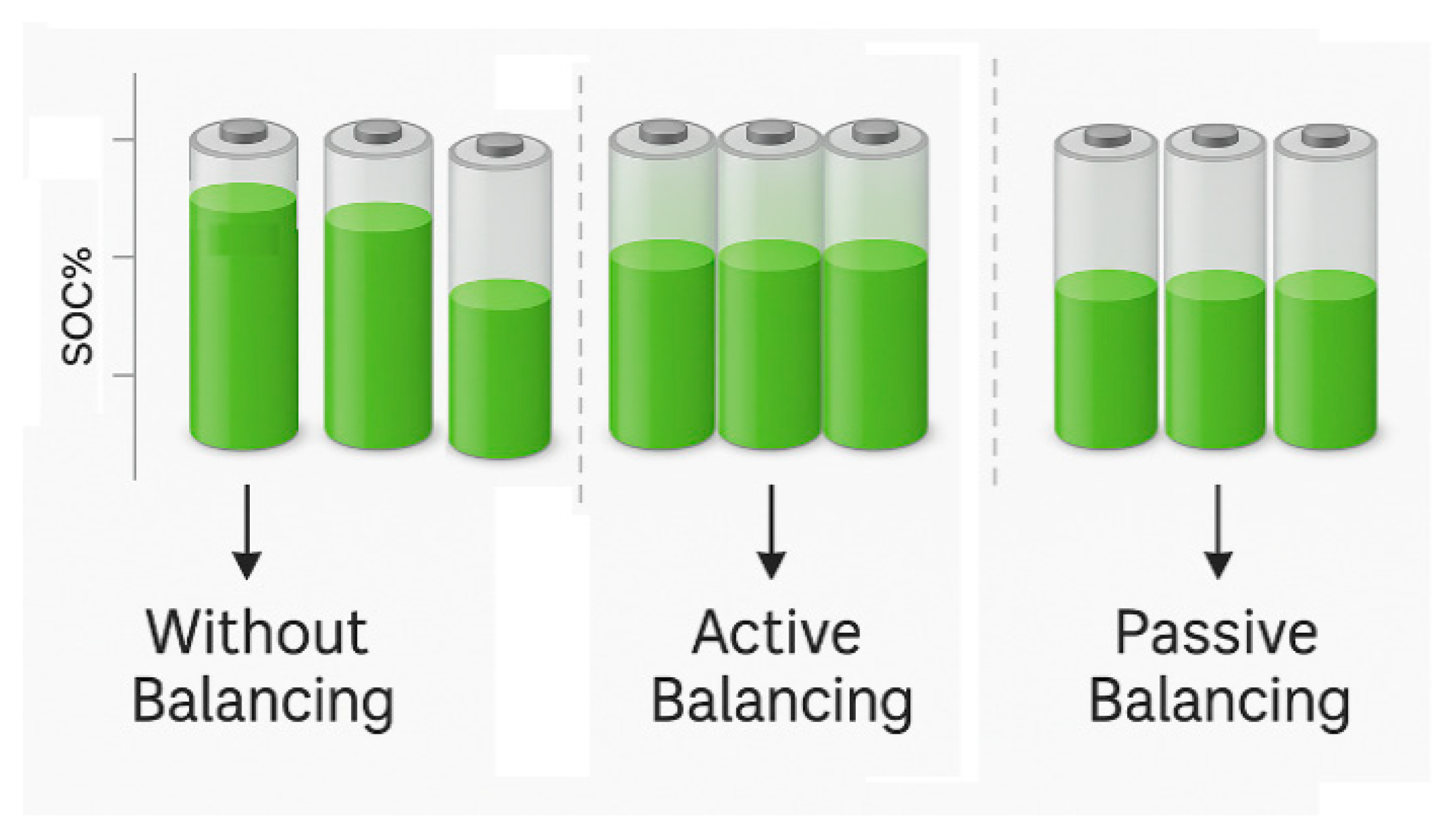
In any multi-cell battery, slight differences cause some cells to charge or discharge faster than others. BMS performs cell balancing to equalize cell voltages and state of charge across the pack [142]. This prevents weaker cells from straying outside safe limits and maximizes the usable capacity of the pack. There are two main methods of cell balancing: passive balancing and active balancing [143].
  • In passive balancing, the BMS takes off excess energy from higher-charge cells as heat via resistors, allowing lower cells to catch up when charging. This method is simpler and used in many EVs, albeit with some energy loss as heat.
  • In active balancing, the BMS redistributes energy from higher-charge cells to lower-charge ones (using capacitor or converter circuits), which is faster and more energy-efficient [143]. Figure 24 presents an explicit pictorial view of cell balancing in both active and passive modes. In active balancing, the charge is distributed equally among the cells, while in the passive mode, the cells take the level of the least charged cell. Active balancing can preserve more energy and potentially extend range, though it adds complexity.
  • Tesla’s packs use passive balancing relying on the cells’ inherent consistency and thermal management, whereas the Nissan Leaf’s BMS employed active balancing to efficiently even out its fewer, larger cells. In both cases, balancing ensures no cell over-charges or over-discharges before the others, protecting overall pack health [144].
  • Voltage and Current Monitoring
  • The BMS measures the voltage of individual cells or groups of cells and keeps them within their safe voltage range (typically 3.0–4.2 V for Li-ion). The BMS prevents over-charge or over-discharge, which could damage the cells [142]. Monitoring current flow in and out of the pack allows tracking of charge/discharge rates and detecting abnormal spikes that may indicate faults. These real-time data are foundational for calculating state-of-charge (SOC) and state-of-health (SOH), ensuring each cell operates within specifications.
  • Temperature Monitoring and Thermal Management
  • Temperature sensors throughout the pack feed data to the BMS so it can maintain each of the cells in an optimal temperature range (often around 15–35 °C) [36,141]. Over-temperature conditions can lead to accelerated degradation or even thermal runaway, while low temperatures affect the pack’s performance. The BMS can activate cooling (e.g., pumps, fans) or heating systems to keep the battery within safe limits [108]. For example, if cells are getting too hot during fast charging or heavy use, the BMS will trigger cooling to prevent overheating. Thermal management is especially critical during fast charging when high current can rapidly heat the pack. Many EVs integrate BMS with a cooling loop or heat pump to enable features like battery pre-conditioning—warming up the battery before fast charging for optimal results [58,122].
  • Battery States Estimation
  • State of Charge (SOC) Estimation
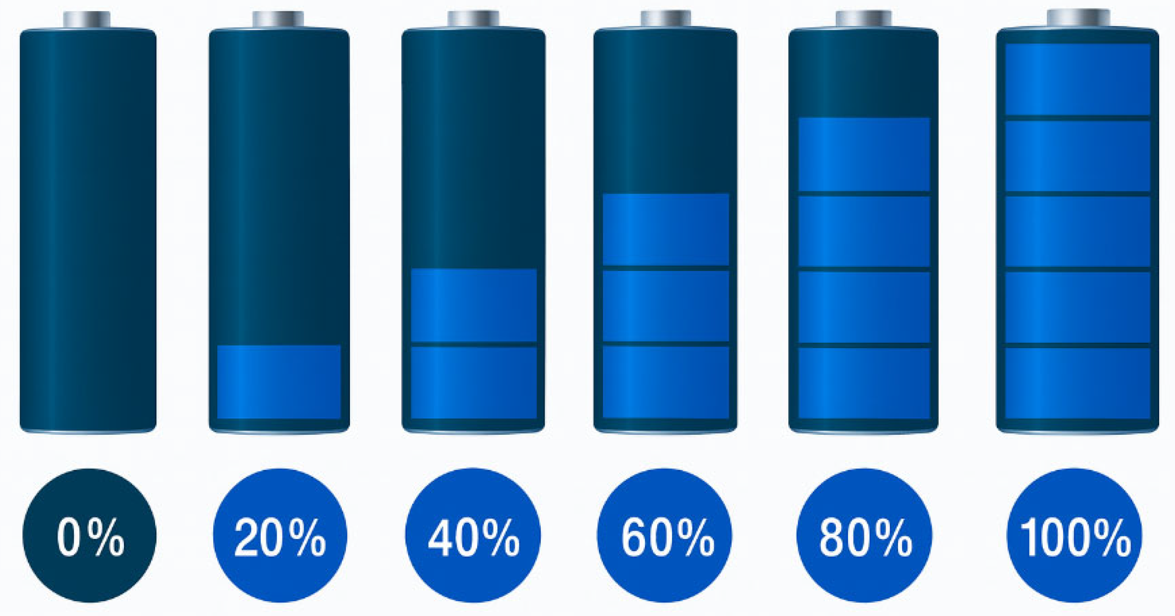
The BMS continuously estimates the battery’s SOC, essentially like the “fuel gauge” of the BEV, indicating remaining charge [145] and evaluating the possible range in miles/kilometers. This is depicted in Figure 25 with the percentage of the remaining charges. It does this by tracking current and voltage changes, applying algorithms or models to infer SOC.
Accurate SOC estimation is challenging but important for predicting range [9,145]. Advanced BMS algorithms use filtering techniques and even machine learning to improve SOC accuracy over time. The SOC data are communicated to the vehicle’s dashboard to inform the driver of range estimation and available charge remaining in the battery [146].
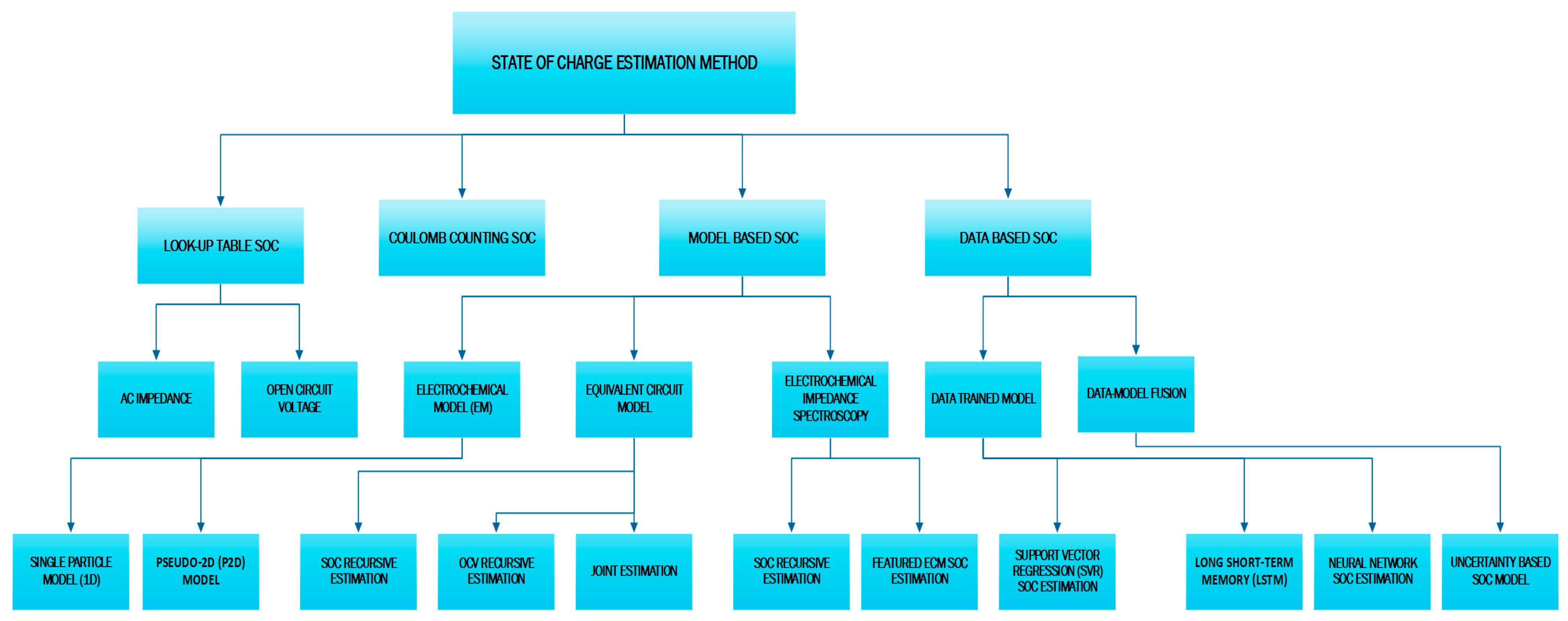
The estimation of SOC is vital in battery management systems (BMS) to monitor battery health, optimize performance, and ensure safety. The methods are broadly classified into four major categories: Look-Up Table SOC Methods, Coulomb Counting SOC, Model-Based SOC, and Data-Based SOC, followed by other sub-categories, see Figure 26. In this paper, we will extensively discuss the model-based state-of-charge (SoC) estimation; readers seeking broader coverage of alternative approaches are referred to the literature.
1.
Look-Up Table SOC Methods
These rely on pre-characterized data from offline experiments and are simple to implement. There are two methods under this category—AC Impedance and Open Circuit Voltage methods. AC Impedance uses battery impedance measured at various frequencies and SOC levels. Impedance characteristics are matched against a look-up table to infer SOC. Pros: Can work dynamically; useful for diagnostics. Cons: Requires complex equipment; less suitable for onboard real-time use. Open Circuit Voltage (OCV) uses the stable relationship between OCV and SOC after the battery is at rest. SOC is interpolated from an OCV–SOC table. Pros: Simple and accurate when the battery is at rest. Cons: Not suitable during active charge/discharge cycles.
2.
Coulomb Counting SOC.
  • Also called the Ampere-Hour Counting method. Measures current over time to calculate charge in/out of the battery. SOC is computed as shown in Equation (4)
    SOC ( t ) = SOC ( 0 ) 1 C nom   0 t I ( t ) d t
    where C nom   is the nominal capacity, I (t) the current going in and out of the battery.
3.
Model-Based SOC
  • These methods use mathematical models to simulate battery behavior and estimate SOC.
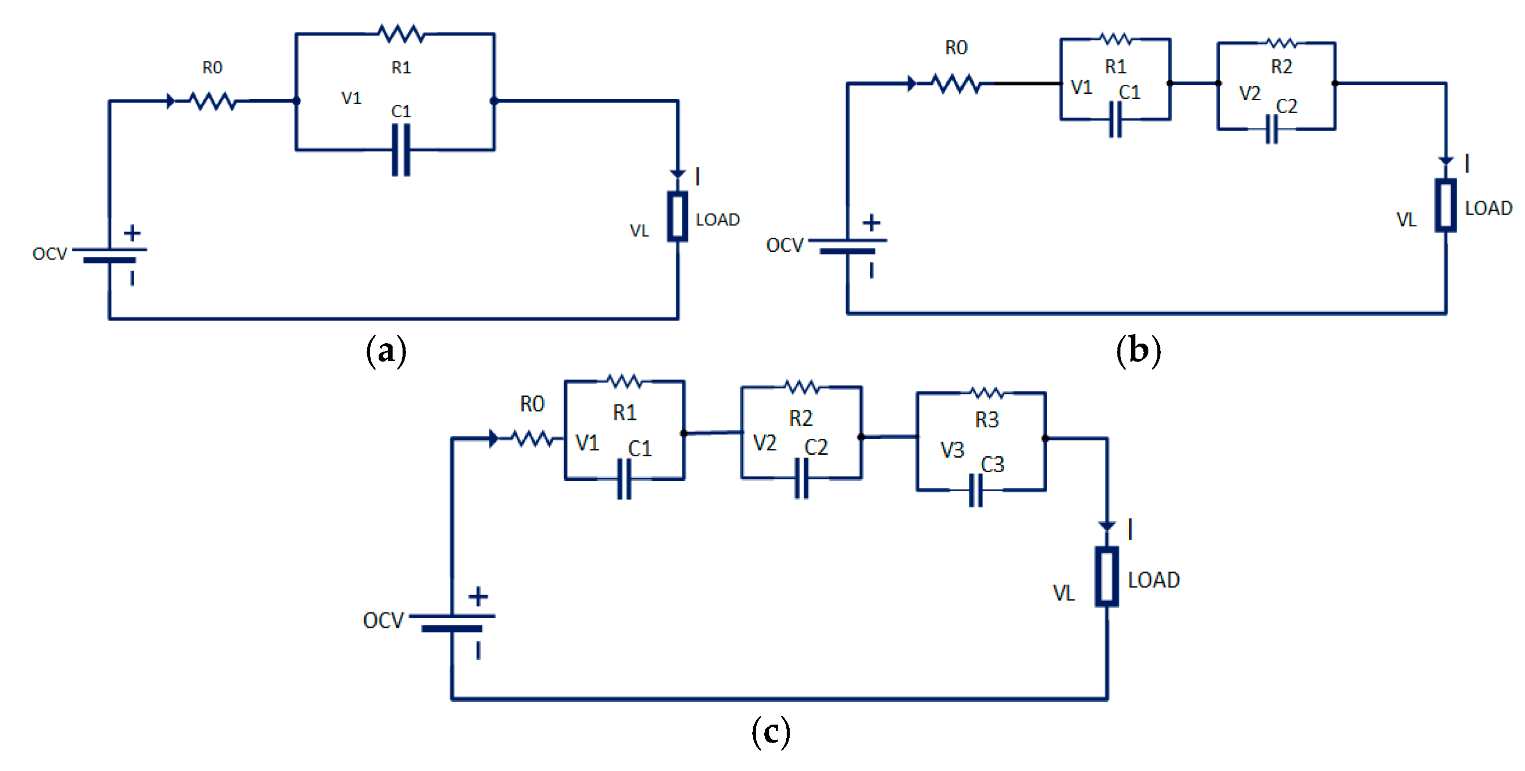
    Equivalent Circuit Model (ECM)—Models shown in Figure 27 the battery using resistors, capacitors, and voltage sources. Widely used due to simplicity and reasonable accuracy.
    Figure 27. (a) 1 RC, (b) 2 RC, and (c) 3RC Battery Equivalent Circuit Models. Figure 27 (ac) Show Battery Equivalent circuit models (ECMs) that approximate battery behavior by resistor and capacitor combinations to capture its voltage dynamics.
    Figure 27. (a) 1 RC, (b) 2 RC, and (c) 3RC Battery Equivalent Circuit Models. Figure 27 (ac) Show Battery Equivalent circuit models (ECMs) that approximate battery behavior by resistor and capacitor combinations to capture its voltage dynamics.
    Wevj 16 00573 g027
A simple R0–C1 model uses an open-circuit voltage source (function of SOC) in series with an ohmic resistor R0 and one RC branch (R1–C1) for transient response. Two-RC and three-RC extensions add additional parallel RC networks (R2–C2, R3–C3) to capture multiple time-constant behaviors, shown in Equations (5)–(13) for each of the RC circuit models. By fitting R and C values at known SOC levels, the model’s impedance features enable real-time SOC estimation via Kalman filtering and other model-based methods.
  • (a)
V L   = O C V ( S O C ) I R 0 V 1
V 1 = ( Q C 1 + I R 1 ) exp ( 1 R 1 C 1 ) I R 1
  • (b)
V L   = O C V ( S O C ) I R 0 V 1 V 2      
V 1 = ( Q C 1 + I R 1 ) exp ( 1 R 1 C 1 ) I R 1  
V 2 = ( Q C 2 + I R 2 ) exp ( 1 R 2 C 2 ) I R 2
  • (c)
V L   = O C V ( S O C ) I R 0 V 1 V 2 V 3
V 1 = ( Q C 1 + I R 1 ) exp ( 1 R 1 C 1 ) I R 1
V 2 = ( Q C 2 + I R 2 ) exp ( 1 R 2 C 2 ) I R 2
V 3 = ( Q C 3 + I R 3 ) exp ( 1 R 3 C 3 ) I R 3
  • Kalman Filtering Algorithm
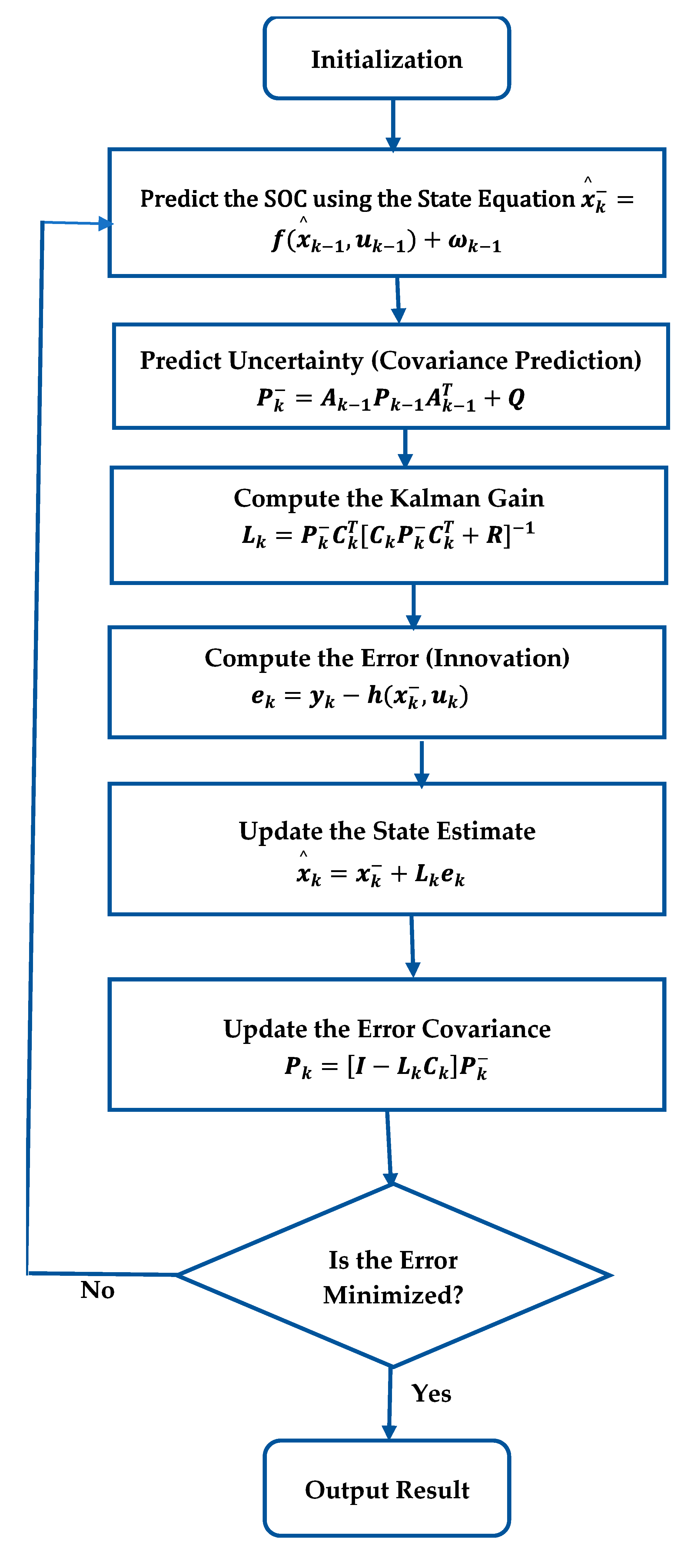
  • Kalman filtering is a widely used model-based algorithm for estimating the Battery State of Charge (SOC) based on equivalent circuit models (ECMs). It recursively updates SOC by combining model predictions with real-time voltage and current measurements, effectively correcting for noise and sensor errors. The Extended Kalman Filter (EKF) is commonly employed due to the nonlinear nature of ECMs. It linearizes the model around the current operating point, improving estimation accuracy. Kalman filtering enhances SOC tracking under dynamic conditions, compensates for uncertainties, and reduces drift associated with methods like Coulomb counting, making it suitable for real-time battery management systems.
Using Figure 28, the entire Kalman filtering algorithm for state of charge estimation can be simply explained in the following lists.
Predict SOC using the State Equation
x ^ k = f ( x ^ k 1 , u k 1 ) + ω k 1
Predict the next SOC ( x ^ k ) based on the previous estimated state ( x ^ k 1 ) and input current u k 1 , f(.) is the nonlinear state transition function derived from the ECM. ω k 1 is the process noise, which accounts for model uncertainties. Note: the SOC is first predicted before seeing the new measurement.
Predict Uncertainty (Covariance Prediction)
Using the formula in Equation (15), we can predict the covariance. The purpose of this is to estimate confidence in the predicted SOC. If the predicted P k is larger than the previous, it indicates higher uncertainty in the prediction.
P k = A k 1 P k 1 A k 1 T + Q
where
  • P k : Predicted error covariance
  • A k 1 : Jacobian matrix (linearized system matrix) from the previous step
  • Q : Process noise covariance.
  • P k 1 : Error Covariance matrix at the previous step
  • State Transition Model (Process Model).
Compute the Kalman Gain
L k = P k C k T [ C k P k C k T + R ] 1
where
  • L k : Kalman Gain—decides how much to trust the new measurement
  • C k : Output model (Jacobian of measurement function)
  • R : measurement noise covariance.
  • For SOC estimation, if the prediction uncertainty is high and the measurement is reliable, the filter trusts the measurement more.
Compute the Error (Innovation)
  • This tells how off the predicted voltage is from the actual measured voltage.
e k = y k h ( x k , u k )
where
  • e k : The difference between the measured output y k and the expected measurement from the prediction h ( x k , u k )
  • h ( . ) : nonlinear output function (e.g., voltage output from ECM).
Update the State Estimate
  • SOC is updated and estimated by combining the predicted value and the scaled measurement error.
x ^ k = x k + L k e k
This is the final corrected SOC at timestep k; it reduces the uncertainty based on the new measurement and ensures future predictions are more confident if current measurements were reliable. This completes the circle of the Kalman filtering process; it repeats until an accurate estimation is reached.
4.
Data-Based SOC
  • Data-driven approaches use machine learning and AI models trained on historical battery data. Data Trained Model uses historical data (voltage, current, temp) to train predictive models. Examples of the data trained models include Support Vector Regression (SVR), SOC Estimation, Long Short-Term Memory (LSTM), Neural Network SOC Estimation, etc. Another new data-based method is the Data-Model Fusion SOC Method, which combines physical models with data-driven insights for robust SOC estimation [9,145]
  • State of Health (SOH) Estimation
State of Health (SOH) indicates the remaining performance capability of a battery compared to its initial (new) condition. It represents the degradation level of battery capacity or internal resistance. The BMS also evaluates the battery’s SOH—a measure of the battery’s overall condition and capacity relative to a new pack [142,146]. By monitoring parameters like cell resistances, capacity fade, and self-discharge, the BMS can gauge how the battery is aging. For instance, comparing each cell’s ability to hold charge or measuring voltage drop under load helps identify weak cells. SOH estimation enables predictive maintenance, forecasting when a pack has deteriorated significantly and is increasingly aided by data analytics and AI to improve its accuracy, since directly measuring capacity fade is non-trivial [146]. SOH can be estimated using the following methods:
There are three main methods of SOH estimation: Direct Measurement Methods, Model-based Methods, and Data-driven Methods.
1.
Direct Measurement Methods
  • Based on capacity measurement by discharging the battery under controlled conditions.
SOH ( % ) =   Current   Capacity   ( Ah )   Nominal   ( Initial )   Capacity   ( Ah ) × 100 %
Based on internal resistance, SOH can be calculated using the expression in Equation (19).
SOH ( % ) =   Initial   Internal   Resistance   ( Ω )   Current   Internal   Resistance   ( Ω ) × 100 %
2.
Model-based Methods
  • These methods rely on mathematical battery models to estimate SOH.
  • Equivalent Circuit Model (ECM): Here, changes in internal parameters like internal resistance and capacitance are analyzed to infer SOH.
R internal   = U OC U Load I Load
SOH = R initial   R internal   × 100 %
3.
Data-driven Methods (Machine Learning)
  • This approach utilizes historical battery data to predict SOH, using Artificial Neural Networks (ANN), Support Vector Machines (SVM), Random Forest, and Gradient Boosting.
  • Safety, Fault Detection and Protection
  • Safety is paramount for EV batteries. The BMS serves as a guardian that can detect fault conditions and take action. It monitors for events such as over-voltage (OV), under-voltage (UV), over-current (OC), short circuits, and over- or under-temperature (OT/UT) situations [9]. If a parameter goes out of the safe range, the BMS will intervene—for example, by disconnecting the battery via contactors to prevent damage. It also enforces proper operation: preventing over-charge that could lead to cell venting or fire, and over-discharge that could permanently damage cells. Modern BMS units often implement redundant safety checks and are designed to meet automotive functional safety standards (like ISO 26262) at high ASIL levels to ensure reliability [147]. They may also include features like “fault codes” or diagnostics that can isolate which cell/module is failing.
  • Communication Interfaces
  • The BMS does not work in isolation; it communicates with other vehicle systems and external devices. Typically, a BMS connects to the vehicle’s control network (often via CAN bus, the Controller Area Network) to exchange data with the Vehicle Control Unit (VCU), charger, thermal system, and more [147]. Through this interface, the BMS can receive commands like the charge current limits from a charger and send out information like SOC, SOH, temperature, or fault alarms. Many EV BMS also support diagnostic connections and sometimes telemetry, for example, logging data to cloud systems or apps [147]. Additionally, some BMS have wireless or Bluetooth capabilities for certain uses (in smaller systems), though in automotive EVs, the primary interface is a wired bus for reliability [148]. As EVs adopt over-the-air (OTA) updates, the BMS firmware itself can be updated remotely to improve algorithms or address issues, which requires secure communication links [148,149]. In summary, robust communication allows the BMS to integrate into the EV’s ecosystem, coordinate charging, and even participate in energy management at a higher level, like vehicle-to-grid scenarios.
  • Data Logging and Diagnostics
  • Modern BMS units record a wealth of data on the battery’s usage—voltages, temperatures, charge cycles, etc. These data provide insight into battery health and can be used for diagnostics and analysis [150]. For example, if an EV experiences an unexpected range drop, service technicians can retrieve BMS logs to see if a particular cell block is weak or if the battery was exposed to extreme temperatures, etc. The BMS’s ongoing “learning” of the battery also allows it to refine its SOC/SOH calculations over time, improving accuracy as it gathers more real-world data. Some automakers implement cloud-connected BMS analytics (digital twin or “battery in the cloud” services) to analyze these data for predictive maintenance [151].

2.2.2. BMS Architecture Variations (Centralized, Modular, Distributed, Wireless)

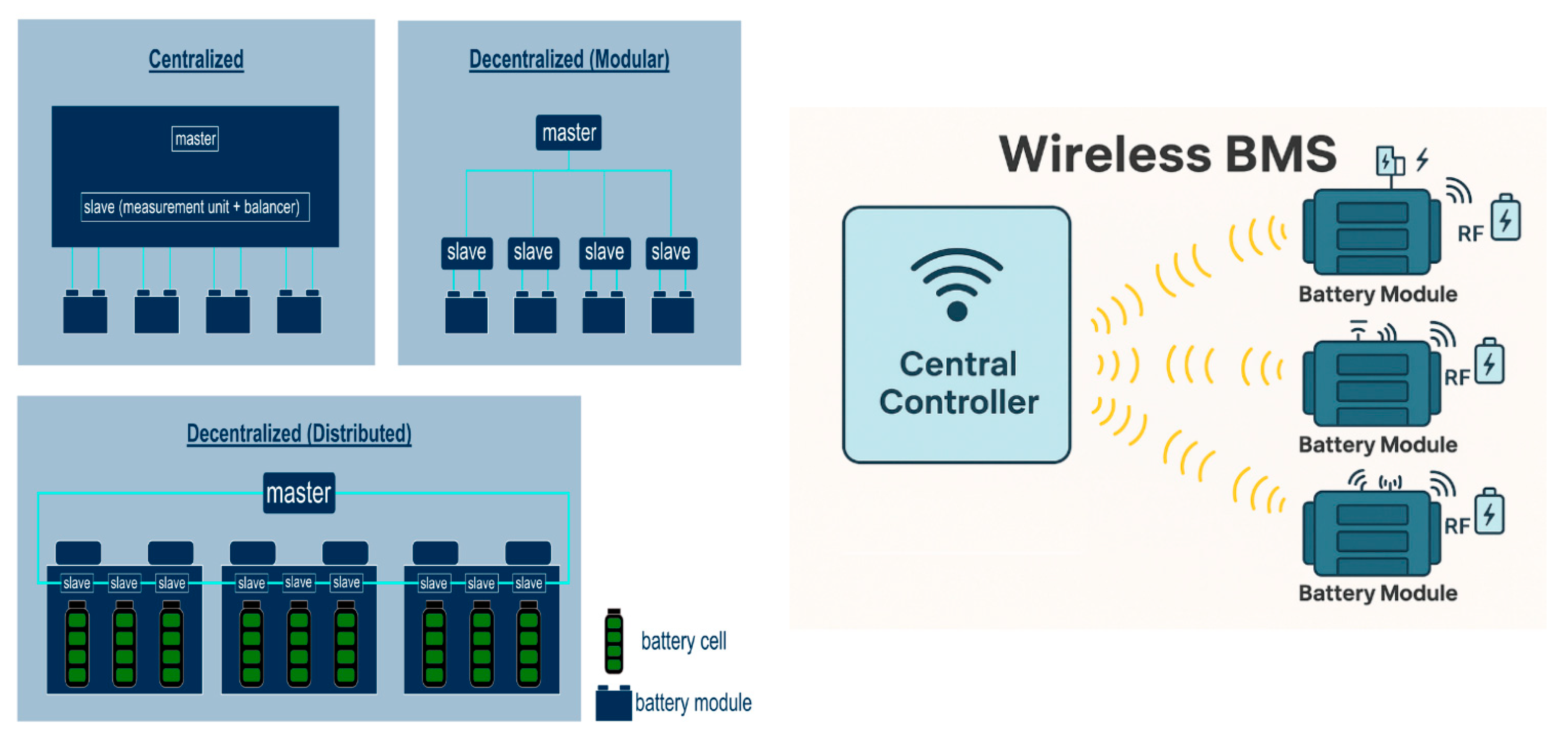
There are several ways to implement a battery management system, depending on how the control and measurement hardware is distributed in the pack. The four main BMS topologies are centralized, modular, distributed, and the emerging wireless BMS, see Figure 29. Each has pros and cons and suits different applications, see Table 2.
  • Centralized BMS
  • In a centralized architecture, one controller (PCB/board) contains most of the BMS circuitry and directly monitors every cell in the battery pack. All voltage sensor wires from the cells and temperature sensors run to this central BMS unit. This architecture is straightforward: a single computer handles data collection, balancing, and protection for the entire pack. Typical calculation for centralized BMS is the following:
Total voltage in the entire pack.
V pack   = V cell   × N series  
Total capacity
C pack   = C cell   × N parallel  
Advantages: Centralized BMS designs are simpler and typically lower cost for small battery packs. With only one control unit, there are fewer components and no complex communication between multiple BMS units. This simplicity makes design, assembly, and maintenance easier. For applications like e-bikes, scooters, or small EVs with low cell counts, a centralized BMS is often sufficient and cost-effective [149].
Figure 29. Centralized, Modular, Distributed, and Wireless BMS Architectures, Reprinted from [152].
Wevj 16 00573 g029
  • Modular BMS
  • Modular BMS splits the battery pack into modules, each with its own local BMS controller board, sometimes called a BMS “slave”, and one higher-level controller that coordinates them. For example, a pack might be divided into 8 modules; each module’s BMS monitors the cells in that module and handles balancing locally, while a central BMS unit (master) connects to each module’s BMS for overall coordination [149]. We can calculate the module voltage using the following expression.
  • Module voltage:
    V module   = V cell   × N series   ( module )
  • Advantages: Modular BMS design is the middle ground that improves scalability. Each module BMS handles a subset of cells, so adding more modules is straightforward for larger capacity or higher voltage packs. Fault tolerance is improved: if one module’s BMS has an issue, it might be isolated to that module rather than turning off the whole pack (depending on design) [147]. Also, modular BMS can simplify pack construction; battery modules can be built as self-contained units with BMS, which are then assembled into packs. This approach was used in the production of EVs: e.g., the Chevy Bolt EV’s pack (60 kWh) was built from multiple smart modules [132].
  • Disadvantages: While modular topologies have simplified pack construction, they require more materials and wiring at the module level, additional controllers, sensors, and connectors. Cross-module synchronization and calibration increase software complexity; more connectors raise assembly time and potential failure points. Pack-level protection coordination (fuses/contactors) and inter-module communication bus loading must be carefully engineered to maintain deterministic fault response. For very small packs, the per-module electronics are a cost penalty versus a centralized design. Modular remains the dominant production choice for passenger-car/bus packs because it balances cost, serviceability, and scalability [153,154].
  • Distributed BMS
  • In a distributed BMS, rather than having a centralized control unit monitoring the entire battery pack, each cell or module has its own small BMS circuit—often called a BMS node or sensor node. These nodes independently measure parameters like voltage, temperature, and current, communicate with a central controller or among themselves using wired or wireless protocols [148,149]. Essentially, the monitoring, balancing, and even protection can be handled at the cell level, with a network of many small BMS nodes.
  • Advantages: This offers maximum scalability and fault tolerance. The system can easily be expanded by adding more cells/nodes—the network self-configures for a larger pack. Fault tolerance is high: if one cell’s BMS node fails, it may affect only that cell and not incapacitate the whole pack. Redundancy and reliability are improved because the network can reroute or tolerate a lost node [154].
  • Distributed BMS can also produce very accurate, synchronized monitoring data from all parts of the pack, useful for advanced control.
  • Disadvantages: Placing controllers at the cell or sub-module level increases part count, standby power, and tight packaging near cells. Synchronized measurement and fail-safe networking across hundreds of nodes demand stringent electromagnetic compatibility. The added silicon increases heat and $/kWh. This method can only be applied in platforms requiring extreme redundancy; fully distributed BMS is rare in mass production due to cost, thermal/electromagnetic compatibility burden, and certification complexity [154].
  • Wireless BMS
  • Wireless BMS (wBMS) is an innovation that can be applied to either modular or distributed systems. In a wireless BMS, the communication between battery module/cell monitoring units and the central controller is done via wireless RF signals instead of a traditional wiring system [149,151]. Each cell module is equipped with a wireless transmitter and a small battery or power harvester to send its data. General Motors was the first to introduce wBMS in production EVs (Ultium platform) in collaboration with Analog Devices and Visteon [27]. Figure 29 is a clear illustration of the Wireless BMS architecture, showing how the central controller wirelessly communicates via RF signals with each battery module node.
  • Advantages: The elimination of long wiring harnesses yields multiple benefits. GM cited up to 90% reduction in BMS wiring and 15% reduction in volume of the pack by removing bulky wire bundles [27]. It also simplifies manufacturing—no complex wire routing means modules can be freely placed and easily assembled or reconfigured. Wireless communication allows modularity: you can mix-and-match module arrangements without redesigning harnesses, which accelerates vehicle development.
  • Another benefit is in maintenance and second-life: modules can be swapped or used outside the vehicle with their BMS nodes communicating wirelessly [148].
  • Disadvantages: Although wBMS reduces harness mass and complexity, RF links must remain deterministic and robust inside a metal-rich, high voltage environment; packet loss, latency, coexistence, and cybersecurity impose stringent design and certification burdens. Powering each node introduces maintenance or reliability trade-offs. Early production exists on select platforms; broader adoption remains limited while automakers validate long-term reliability, safety, and total cost benefits versus proven wired modular systems [153,155]. Table 3 bellow shows the automakers and their models with different BMS features.

2.2.3. Future Trends in BMS Design

  • AI-Based State Estimation and Management
  • Future BMS will embed AI/ML models instead of static lookup tables, using patterns in voltage, current, temperature, and usage history to predict SOC and SOH with higher accuracy [9,146]. Edge-embedded learning enables dynamic optimization of charging protocols and thermal control, early anomaly detection like internal short circuit, and proactive maintenance alerts.
  • Digital Twin Integration
  • Cloud-connected BMS will mirror each battery via a real-time digital twin, using actual data and AI to simulate aging and performance [151]. Automakers can adjust charging profiles or thermal limits based on twin predictions, meet warranty regulations, and deliver over-the-air updates. Users gain “health forecasts,” enabling smarter usage and longer life.
  • BMS for Solid-State and New Chemistries
  • Next-generation BMS hardware and software will be chemistry-agnostic, adding new sensors (pressure, acoustic) and AI-driven algorithms to manage solid-state, lithium-sulfur, or sodium-ion cells. They will enforce tailored charge regimes, integrate tighter thermal control for cells, and employ redundant sensing to ensure safety across various chemistries on a common platform [156].
  • Vehicle-to-Grid (V2G) and Energy Ecosystem Control
  • Future BMS will interface directly with smart grids via ISO 15118-20 protocols [157], autonomously coordinating charge/discharge to provide frequency regulation, demand response, or user-defined V2G limits. Integrated scheduling will optimize cost and renewables availability, while robust cybersecurity prevents unauthorized grid commands, making each EV an active, secure node in the energy ecosystem [156].
  • Enhanced Cybersecurity and Functional Safety
  • With greater connectivity, BMS will adopt hardware security modules for encrypted communication and secure boot, comply with updated requirements, and feature redundant processors for fail-safe operation [151,156]. Real-time AI anomaly detection will become mandatory, isolating cell faults before thermal events, while secure over-the-air updates guard against malicious attacks throughout the battery’s life [149].
  • Modular, Reusable BMS and Second-Life Integration
  • BMS architecture will become highly modular and standardized, enabling seamless repurposing of retired EV packs for stationary storage. Each module will export “aging transfer” metadata to inform second-life controllers, while stackable BMS boards allow rapid scaling for diverse pack sizes. This design will maximize manufacturability, sustainability, and lifecycle value.

3. Electric Motor in BEV

Battery Electric Vehicle (EV) propulsion relies on advanced electric motors that convert battery power into motion. Unlike internal combustion engines, BEV motors are highly efficient and provide instant torque, but various motor designs offer different trade-offs in efficiency, power density, cost, and complexity [158,159,160]. This paper will provide a comprehensive overview of motor configuration in Battery Electric Vehicles and main motor types used in battery BEVs—which include Permanent Magnet Synchronous Motors (PMSM), Induction Motors (Asynchronous), Switched Reluctance Motors (SRM), and Axial Flux Motors, and other relevant types [158] detailing their technical characteristics, typical use cases, and pros/cons. We also identify which automakers and models use each motor type, highlighting industry trends such as shifts from induction to permanent magnet drives. Finally, we discuss emerging motor technologies and design innovations aimed at improving performance, efficiency, and sustainability in the next generation of EVs.

3.1. Battery Electric Vehicle Motor Configurations

Battery-electric vehicle (BEV) drivetrains are typically classified into two types: hub-mounted motors and integrated e-axle motors [161]. Hub motors sit directly at the wheel hub, doing away with traditional axles and gearsets to deliver greater efficiency, more compact motor-inverter packaging, and a lower vehicle floor [158]. E-axle (electric axle drive) has the propulsion motor, inverter, and transmission built into a single unit, streamlining power conversion, torque distribution, and overall drivetrain integration
Both E-Axles and Hub Motors are used in EVs for power transmission, but they differ in design, efficiency, and application.
Hub Motors are better for: Light electric vehicles, e-bikes, e-scooters, urban EVs, Autonomous pods, or small city cars. It is best for applications needing maximum energy efficiency with no transmission losses [162]. Hub motors remain rare in BEVs because of the added unsprang mass, difficult ride handling, and (Noise, Vibration and Harshness- NVH ratio), and the wheel structure makes cooling difficult—raising durability and thermal risk [163].
E-Axle is better for: High-speed and high-power EVs, Tesla, Nissan Leaf, Rivian, BMW iX, etc, vehicles requiring long-range efficiency. It provides more passenger comfort and off-road capabilities [164]. In general, E-Axles dominate current EVs due to better performance, cooling, and comfort.
BEVs do not use DC motors because of insufficient torque at high speeds and rapid wearing out of commutators. Single-phase AC motors are also avoided because they do not deliver sufficient starting torque [158,161].
Three-phase AC motors offer BEVs high torque from middle to high speeds that can be further tuned to the needs of the drivetrain. BEVs use one of three types of three-phase AC motors—induction, permanent magnet synchronous, and permanent magnet synchronous reluctance motors [158].

3.2. BEV Motor Types and Their Characteristics

3.2.1. Permanent Magnet Synchronous Motors (PMSM)

PMSMs, often called permanent magnet AC motors, are the dominant motor type in modern BEVs. In a PMSM, the rotor contains strong permanent magnets, usually rare-earth magnets like Neodymium-Iron-Boron that create a constant magnetic field [158,165]. The stator, carrying three-phase windings, is driven by an inverter to produce a rotating magnetic field which locks in synchronism with the rotor’s field—hence “synchronous.” There is no slip between the rotor and stator fields under normal operation.
PMSMs can be designed with magnets on the surface of the rotor or embedded inside the rotor’s interior permanent magnets, the latter often being used in EVs to improve high-speed performance by leveraging reluctance torque.
Characteristics: PMSMs are prized for their high efficiency and power density. Automotive PMSMs routinely achieve efficiencies above 90% range, making PMSM “the king of efficiency,” reaching about 94–95% in traction applications [165].
The permanent magnets provide a constant field without consuming electrical energy, which boosts efficiency, especially at low and medium loads. Power and torque density are also high because the magnetic field in the rotor is strong and does not require current in the rotor—no rotor copper losses. PMSMs can deliver high torque even from zero speed and maintain good performance over a broad speed range. Thermal management is somewhat easier than in induction machines since only the stator windings generate significant heat in a PMSM; the rotor magnets have negligible losses [166]. Figure 30 showcases the interior of a permanent-magnet synchronous motor (IPMSM): copper stator coils surround a salient rotor with embedded permanent magnets.
Note: Currently, all automotive PMSMs used for Battery Electric Vehicles are radial-flux motors, with the permanent-magnet rotor at the center and the stator wound around it. The flux path runs radially from rotor magnets through the air gap into the stator iron [158]. Generally, radial-flux motors are the workhorse of today’s BEVs.
Figure 31 illustrates a PMSM drive system in a BEV. The DC supply from the EV battery pack feeds a traction inverter/converter, converting DC to three-phase AC currents (Ia, Ib, Ic) to drive the PMS motor connected to the vehicle’s wheels. A position sensor detects the rotor position and sends feedback to the controller, which adjusts control signals for the inverter to regulate speed and torque based on input commands. This closed-loop system enables precise, efficient motor control, ensuring smooth and responsive vehicle propulsion while optimizing performance and energy use.
  • Advantages of PMSM
  • PMSMs deliver excellent efficiency (up to 95%), resulting in superior BEV range. Their high torque and power density make them ideal for compact vehicles, while quick response and no slip enable precise control and effective regenerative braking. Lower rotor losses also reduce heat dissipation and therefore minimize cooling requirements.
  • Disadvantages of PMSM:
  • Use of Rare Earth Materials: Permanent magnet motors rely on rare-earth materials, which are costly. They are more expensive than other designs, risk partial demagnetization under fault or overheating, and experience drag losses when unpowered.
  • BEVs that Use PMSM
  • Permanent magnet motors are used by the majority of modern BEVs, especially when a single motor is employed for primary traction [158]. Their combination of efficiency and compact size makes them the default choice. For example, the Nissan Leaf, Chevy Bolt EV, Ford Mustang Mach-E, Jaguar I-Pace, Porsche Taycan, Audi e-tron GT, and Hyundai/Kia E-GMP models (Ioniq 5, Kia EV6, etc.) all use PMSMs for propulsion [25,123,168]. Tesla has also moved to PMSMs—the Model 3 uses an IPM synchronous motor. Tesla’s first use of magnets was after the Model S/X initially used induction machines [169]. Recently, industry-wide, there has been a clear trend toward PMSMs for new BEV models. Ford has also keyed in on using Permanent Magnet Motors after discovering that they are more efficient than the induction motors they used before [169]. Others who started on induction are moving to permanent magnets.

3.2.2. Induction Motors

Induction motors, or asynchronous AC motors, invented by Nikola Tesla, feature a rotor made of conductive bars (the “squirrel cage”) without permanent magnets. AC current in the stator creates a rotating magnetic field, inducing currents in the rotor and producing torque [170]. The rotor’s field lags, causing “slip,” hence the asynchronous name. These motors require no rare-earth magnets or brushes, making them robust and cost-effective. Automotive three-phase induction motors reach about 90% efficiency—slightly lower than PMSMs—but are durable and have high overload tolerance, as they withstand high temperatures and momentary torque surges without demagnetization. However, induction motors are typically larger and heavier for the same output, due to less efficient rotor field generation and higher heat production (rotor I2R losses), necessitating active cooling [158]. Used in EVs like the Tesla Roadster and Model S, all EV induction motors are radial-flux designs, producing a rotating radial field for torque, with proven ruggedness and reliability.
Figure 32 is the exploded view of an EV induction motor for Audi Q3. The stator (copper windings, center) creates a rotating field that induces currents in the rotor, producing torque.
  • BEVs That Use Induction Motors
  • Induction motors have been pivotal in BEVs, especially with Tesla’s early Roadster and Model S/Model X rear drives. Dual-motor AWD models like Tesla’s Model 3, Model Y, and Volkswagen’s ID.4/Audi Q4 e-tron use induction motors on the front axle for extra power or traction, combined with PMSMs at the rear. Mercedes-Benz EQC initially featured induction motors. Though PMSMs dominate new designs, induction motors remain important for their robustness and overload capability in multi-motor setups [172,173].
  • Table 4 summarizes electric vehicle models across major automakers and their traction motor architecture used in each.
Table 4. Examples of EV Models and Their Motor Types [16,20,32,135,168,171,174,175,176].
Manufacturer and ModelMotor Type(s)Notes
Tesla Model S (2012–2018)AC InductionEarly Tesla strategy
Tesla Model 3/YPMSM + Induction (AWD)PMSM primary, induction secondary
Tesla Model S Plaid (2021)3× PMSMHigh-performance PM
GM EV1 (1996)AC InductionEarly EV, industrial motor
Chevy Bolt EV (2017)PMSMEfficiency, range
GMC Hummer EV (2022)3× PMSMRare-earth minimized
Cadillac Lyriq (2023)1–2× PMSMGM’s standard PM motors
Ford Mach-E (2021)PMSM (RWD/AWD)Efficiency-focused
Ford F-150 Lightning (2022)2× PMSMDurability, torque
Nissan Leaf (2010)PMSMCompact, early mass EV
Nissan Ariya (2022)2× PMSM (AWD)PM with inverter efficiency
BMW i3 (2013)PMSM (reduced magnets)Magnet-reduced design
BMW iX/i4 (2021)EESM (no magnets)Magnet-free innovation
Audi e-tron SUV (2019)2× AC InductionEarly non-PM, less efficient
Audi e-tron GT/Porsche Taycan (2021)2× PMSMPerformance-focused PM
VW ID.4 RWD (2020)PMSMStandard MEB motor
VW ID.4 AWD/Audi Q4 e-tronPMSM + InductionAWD efficiency
BYD Han EV (2020)PMSMPrimary PM design
BYD Seal AWD (2022)PMSM + InductionMixed-motor setup
Hyundai Ioniq 5/Kia EV6 (2021)PMSMClutch-disconnect front
Rivian R1T Quad (2022)4× PMSMTorque vectoring
Lucid Air (2022)2–3× PMSMHigh-power density
NIO ET7 (2022)PMSM + InductionPerformance-focused mix
  • Comparing PMSM Versus IM
PMSMs tend to deliver higher efficiency, especially at low to moderate loads and higher continuous torque density, directly benefiting range and performance [158,165]. PMSMs provide full torque at zero speed inherently, whereas IMs require a bit of slip and appropriate inverter control to produce torque, though in practice they also can produce full starting torque if the inverter drives them with the appropriate frequency—torque at zero speed is not a limitation of IM in vector control [165]. Induction motors excel in cost and robustness, and have a naturally broad speed range with no magnet-induced limits [177]. For instance, the Tesla Model S’s induction motor could run up to 16,000 rpm, enabling a 250 km/h top speed, while its newer PMSMs in Model 3 are engineered with interior magnets and reluctance assist to also reach high RPM but with a more complex design. From an efficiency standpoint, tests and models often show an IM might be 2–5% less efficient at part load, which for an EV can translate to several percent less range. Therefore, most automakers have gravitated to PMSMs as the primary traction motor in BEVs to maximize range. Table 5 summarizes key differences between a representative PMSM and an induction motor in EV use.
In practice, modern BEVs achieve excellent performance with both types, but PMSMs currently dominate new designs due to efficiency and packaging advantages. Induction machines still see use in certain dual-motor configurations for their robustness and low-drag characteristics.
Beyond PMSM and IM, several alternative motor types are being explored for niche roles: wound-rotor synchronous motors (WRSM), also called electrically excited synchronous motors (EESM) [175], replacing permanent magnets with a coil-excited rotor to avoid rare-earths and enable tunable flux for a wider constant-power region and strong high-speed efficiency—proven in production by Renault (e.g., ZOE and newer E-Tech models) [178]. Although they introduce an excitation subsystem like contactless exciter, rotor copper losses/heat, and added control-electronics complexity; switched reluctance motors (SRM) offer simple construction and high-speed capability but suffer higher torque ripple and acoustic noise; axial-flux motors (pancake form factor) deliver high torque in short axial length and appear in some premium and startup designs; and in-wheel hub motors maximize packaging by eliminating axles but increase unsprang mass and pose durability challenges. Despite this diversity, most commercial BEVs still favor inboard radial-flux PMSM or IM with a reduction gear because the technology is mature, efficient, and reliable.

3.2.3. Emerging and Future Motor Technologies in BEVs

Looking ahead, the EV industry is actively researching and developing new motor technologies to further improve performance, efficiency, and sustainability. These emerging technologies include the following:
1.
Integration and Compact Efficiency:
  • Automakers are increasingly integrating motors, inverters, and gearboxes into single compact units (e-axles) to improve efficiency, save space, and reduce overall vehicle weight.
2.
Advanced Cooling Techniques:
  • Innovative cooling solutions like oil spray, immersion, or shared thermal management are enabling motors to achieve higher continuous power ratings and improved durability.
3.
Higher RPM Motors and Multi-Speed Transmissions:
  • Next-generation EVs are adopting high-RPM motors and multi-speed transmissions to maximize power density and efficiency while optimizing performance across driving conditions.
4.
New Materials and Manufacturing:
  • Research is focused on new magnet chemistries, cobalt-free or cerium-based materials, and additive manufacturing to lower costs, improve thermal stability, and enable advanced motor designs.
5.
AI in Motor Design and Control:
  • AI and machine learning are increasingly used to optimize motor design, torque management, and real-time control for greater performance, efficiency, and material savings.

4. Power Electronics Converters in BEVs

Power-electronics converters are the critical link between the high-voltage battery pack and every electrical subsystem in a battery-electric vehicle (BEV) [179]. They control and condition energy flow for propulsion, charging, and auxiliary systems. Figure 33 depicts the power electronics components in battery electric vehicles and how they interact with other subsystems. Also in this section, we will do a comprehensive overview of the major converter types, their topologies and semiconductor technologies, and how leading EV manufacturers implement them.

4.1. Onboard Charger

Onboard Chargers (OBC) support either unidirectional or bidirectional power transfer to the battery and are designed to work with Level 1 and Level 2 chargers, considering constraints such as size, weight, volume, and power capacity. Typically, they employ a two-stage converter architecture, consisting of an AC-DC conversion stage at the input and a DC-DC conversion stage at the output [180]. In general, the front-end of an onboard charger consists of a grid-connected passive rectifier followed by a boost converter functioning as a power factor correction (PFC) stage. This setup delivers regulated power through a DC link to the onboard DC-DC converter, which then charges the battery [181]. The front-end rectifier stage in onboard chargers can be implemented using half-bridge, full-bridge, or multilevel converter topologies. Onboard charging typically supports lower power transfer, resulting in longer charging times compared to offboard systems. A typical onboard charger configuration is illustrated in Figure 34. These chargers can handle AC power levels of 1.9 kW for Level 1 and up to 19.2 kW for Level 2 charging. The AC power from the charging station is directly supplied to the onboard AC-DC rectifier. Subsequently, a DC-DC converter regulates the output to the appropriate power level and delivers energy to the battery pack through a protection circuit, which communicates with the Battery Management System (BMS) and the power control unit [182].
Traditional onboard chargers, also known as dedicated systems, typically employ two separate power converters—one for charging the battery and another for motor control, as illustrated in Figure 35a. These dedicated chargers often face limitations in terms of power handling due to constraints related to vehicle size, cost, and weight [183]. To address these challenges, integrated onboard charger designs have been developed, which merge the charging function with the motor drive system using a single AC-DC converter, as depicted in Figure 35b. This approach allows the battery to be charged through the existing propulsion components, eliminating the need for bulky and specialized hardware [184]. The following section reviews both Stand-alone and Propulsion-integrated onboard charger systems, highlighting current commercial implementations and topologies.
Most inverters are 2-level three-phase bridges, but 800 V systems often use 3-level or modular multilevel converters to handle higher voltage stress. Heat dissipation is managed by liquid-cooling blocks or direct-cooled packages [185]. Efficiency at high switching frequencies is critical. Rather than presenting a series of onboard charger (OBC) topologies, this paper introduces a single and unified architecture, as shown in Figure 36, that encapsulates the essential structure of a state-of-the-art bidirectional charging system. Critical distinctive features include topological variants, rectifier choices, DC-DC converter arrangements, and advanced features such as bidirectional energy flow.
The design incorporates EMI filtering, AC-DC rectification, a bidirectional buck-boost stage, and a galvanically isolated Dual Active Bridge (DAB) converter interfaced with the EV battery. This design concept was adapted from Refs. [186,187]. The S1, S2, S3… are switching devices like MOSFETs, IGBTs, and Silicon Carbide (SiC).

4.2. Traction Inverter (DC to AC)

This is typically a three-phase inverter using six or more power transistors (IGBTs or MOSFETs) to create a variable-frequency AC output that drives the motor [188]. Inverters in modern EVs often operate at switching frequencies of 10–20 kHz (Silicon IGBTs) or even higher, 20–40 kHz with Silicon Carbide MOSFETs to achieve smooth current waveforms [185,188,189]. The key design goal is high efficiency over the drive cycle; any inverter loss turns into heat that must be removed. Losses in power electronics come from two main mechanisms: conduction losses, i.e., when the device is on, due to its finite on-resistance, and switching losses, i.e., energy dissipated during each on-off transition, as voltage and current overlap in the device.
Traditionally, EV inverters used silicon IGBTs, which have relatively low conduction loss at high currents but significant switching losses, and cannot switch extremely fast due to tail currents. A balance between conduction and switching losses leads to an optimal switching frequency for given devices. For example, an IGBT-based inverter might switch around 10 kHz to keep switching losses manageable; increasing to 20 kHz would reduce current ripple (better motor performance) but incur much higher losses, overheating the device [188].
The introduction of Wide Bandgap (WBG) semiconductors, especially Silicon Carbide (SiC) MOSFETs, is a game-changer. SiC MOSFETs have much lower switching loss and can operate at higher junction temperatures. They also have no significant tail current and lower on-state resistance at high voltage. This allows inverter designers to raise switching frequencies (e.g., 50 kHz or more is feasible) and/or improve efficiency at the same frequency compared to IGBTs [186,190].
Many new BEVs, particularly those with 800 V battery systems (Porsche Taycan, Audi e-tron GT, Hyundai Ioniq 5/6, Lucid Air) [29,191,192], use SiC-based inverters to handle the high voltage efficiently. For instance, an analysis by Renesas indicated that moving from a 400 V IGBT inverter to an 800 V SiC inverter can cut total power losses by several percent and allow much higher power throughput with the same cooling capacity [186].
Lower losses not only extend range (by reducing wasted energy) but also enable more aggressive driving without derating. One tradeoff is cost—SiC devices are still more expensive than silicon IGBTs, though the gap is closing as production scales. Some manufacturers stick to IGBTs for cost-sensitive models (e.g., Nissan Leaf’s inverter is IGBT-based 400 V), whereas luxury/high-performance models and new platforms (GM’s Ultium, Tesla’s latest, etc.) are increasingly all-SiC.
To further reduce losses, inverter designers employ techniques like soft-switching topologies or advanced modulation [179]. However, in motor drive inverters, space for resonant or soft-switch circuits is limited, so most rely on improving the devices themselves and using optimal gate drive and modulation schemes [179,190]. Innovations such as using multi-level inverters (splitting the DC bus into multiple levels to reduce voltage steps) have been explored to improve efficiency and reduce harmonics, but most production BEVs still use two-level three-phase inverters due to simplicity and reliability [188,189].

4.3. HV-To-LV DC/DC Converters

BEVs typically have a DC/DC converter to step down from the high-voltage pack (which could be 400 V or 800 V nominal) to the 12 V system that powers lights, infotainment, power steering, etc., and keeps the 12 V battery charged [193]. This is usually a unidirectional or bidirectional converter in the few kW range. Efficiency is also important here to avoid draining the HV battery unnecessarily. These converters often use high-frequency switching (100–500 kHz) with modern MOSFETs and synchronous rectification to achieve >95% efficiency. Some EVs use a simple buck converter topology, while others use resonant or soft-switch designs for even lower losses. For instance, a phase-shift full bridge or Inductor–Inductor–Capacitor (LLC) resonant converter can be used to achieve zero-voltage or zero-current switching, significantly cutting switching losses [186,190].
In fact, the LLC resonant converter topology has become popular in on-board chargers and some DC/DC stages because it can operate with zero-voltage-switching (ZVS) over a wide range, meaning the transistors turn on when the voltage is near zero, virtually eliminating turn-on losses. An example is Toyota’s 6.6 kW onboard charger, which uses an interleaved power factor correction (PFC) front end and an LLC resonant DC/DC stage—achieving 96% efficiency with switching frequencies in the hundreds of kHz [190].
Many modern EVs adopt a dual-battery strategy, which comprises the HV battery, a 48 V intermediate bus, and a 12 V bus. In this case, an isolated or non-isolated stage creates 48 V from HV, and a second stage or point-of-load converters creates 12 V [190,193]. The converter should be able to handle 1–3 kW continuously. As an example, some Chinese EV platforms (NIO, BYD) use an intermediate 48 V battery for major loads and step that to 12 V—silicon MOSFETs suffice for these DC/DC stages [194].

4.4. High-Voltage Systems (400 V vs. 800 V)

The industry is gradually moving from 400 V nominal battery systems to 800 V in higher-end EVs [193,195,196]. The main benefit is that for the same power, doubling the voltage halves the current, which significantly reduces I2R losses in cables and allows faster charging (an 800 V pack can accept 350 kW charging at 437 A, whereas a 400 V pack would need 875 A for 350 kW, which is impractical without liquid-cooled cables [196,197]. However, going to 800 V requires all power electronics to handle 800+ V, which historically was difficult for silicon IGBTs (they exist up to 1200 V but with compromises). This is where SiC shines—1200 V SiC MOSFETs can easily handle 800 V systems with efficiency. By 2025, several platforms (Porsche/Audi J1, Hyundai E-GMP, GM Ultium, etc.) will use 800 V batteries and SiC inverters/OBC to leverage this benefit. These vehicles can typically charge at 270–350 kW on compatible DC stations, adding ~300 km range in 15–20 min, a key selling point.

4.5. Auxiliary Converters, Power Cabin Electronics, and Accessories

Auxiliary power converters play a vital role in modern EVs by powering a wide range of cabin electronics and vehicle accessories. The DC/DC converter steps down high-voltage battery pack power to supply traditional 12 V systems, which continue to operate lights, infotainment, instrument clusters, airbags, and controllers for window motors and door locks. Many EVs also feature DC/AC inverters that provide standard AC outlets for external devices—supporting Vehicle-to-Load (V2L) and Vehicle-to-Home/Building (V2B) applications, such as powering tools, camping equipment, or even homes during outages. Additionally, high-powered auxiliary converters supply specialized loads like electric HVAC compressors, coolant or refrigerant pumps, and electric power steering [193,197]. While 12 V lead-acid or AGM batteries remain common for auxiliary system support, an increasing number of automakers—including Rivian and Mercedes-Benz EQ models are transitioning to 48 V accessory buses to minimize wiring size, reduce current loads, and enable more efficient support of next-generation high-power accessories, further enhancing system reliability and efficiency.
Generally, power electronics advancements have been pivotal in improving BEV performance and efficiency. The shift to SiC MOSFETs and resonant/soft-switching topologies has significantly reduced the loss and volume of converters [197]
As a result, today’s BEVs often achieve overall drivetrain efficiencies (battery-to-wheels) of about 85–90%, an impressive figure considering the multiple conversion stages, much higher than an ICE vehicle’s 20–30% tank-to-wheels efficiency [198]. Losses that remain in the 10–15% range are roughly split between motor/inverter and other factors like gearbox and auxiliary loads. Further improvements in power electronics will target that last few percent, which becomes increasingly challenging, e.g., going from 97% to 99% efficiency cuts losses by a factor of 3, but demands near perfection in design [199].

4.6. Future Trends in EV Power Electronics

Future power converters may incorporate GaN (Gallium Nitride) devices for lower-voltage applications (GaN FETs are emerging for 650 V or less, potentially useful for DC/DC or 400 V systems for even higher frequency operation) [196,200,201]. Integration and modularization will likely continue: one vision is a single “Power Electronics Hub” that manages all conversion tasks dynamically—e.g., if the car is coasting, the inverter could dynamically reconfigure to charge the 12 V battery or perform some other function [196]. While not yet at that stage, there are research ideas for multiport converters that can seamlessly direct power between battery, motor, grid, and auxiliaries as needed. The drive for ever higher power density also continues (to save space/weight); techniques like 3D packaging, better cooling (perhaps using the coolant to directly cool semiconductor substrates or using dual-sided cooling), and advanced control (to reduce EMI and allow smaller filters) are all being worked on. Ultimately, the trend in power electronics is toward invisibility: converters so efficient and compact that the user never has to think about them—they just quietly do their job with minimal impact on vehicle range or performance.
Table 6 presents BEV automakers and their respective traction inverter, OBC, and DC/DC solutions, including supplier information. The comparison underscores differing design trade-offs in cost, efficiency, and integration.

5. Energy Management Systems in BEVs

Energy management systems (EMS) in battery-electric vehicles (BEVs) act as the “brain” of the powertrain, coordinating energy flows in the entire system of the vehicle—battery, motors, charging system, auxiliary systems, and the power electronics components [202]. Typical EMS collects data (e.g., battery voltage, current, temperatures, vehicle speed) from the battery management system (BMS) and other sensors and issues commands to subsystems, motor inverter, HVAC, and charger to meet driver demand while maximizing efficiency [147,203]. Figure 37 shows how Battery-Electric Vehicle’s Energy Management System (EMS) sits at the heart of all power flows and control signals in the drivetrain. It constantly orchestrates all power-electronic elements: charging, discharging, DC/DC conversion, motor drive, and regen capture, while managing low-voltage auxiliaries to maximize performance, safety, and energy efficiency.

5.1. Key EMS Functions Include

Energy Flow Control and Power Distribution: The EMS allocates power from the high-voltage battery to the electric motor(s), auxiliary systems, and cabin climate. It balances multi-motor outputs (in AWD or dual-motor BEVs) and decides how much braking torque is regenerative [204,205]. Effective energy flow control ensures smooth acceleration/deceleration and safe operation under all conditions.
Thermal Management Coordination: The EMS ensures that battery cells and power electronics stay within optimal temperature ranges. Since BEVs lack an engine heat source, the EMS must judiciously use the HVAC (heater, chiller, heat pumps) to warm or cool the battery and cabin without unduly draining battery energy [203]. EMS must maintain optimal battery temperature and cool the battery, especially during fast charging. In practice, the EMS will precondition the battery for charging or reconfigure coolant flow (via valves/pumps) based on driving or charging needs [206].
Regenerative Braking Control: The EMS determines how aggressively to apply regenerative braking (regen) when the driver lifts off the accelerator or applies brakes. It manages the switch between motoring and generating modes of the inverter [205]. EMS logic can maximize energy recovery (one-pedal driving) or blend regen with friction brakes for comfort. For instance, some Hyundai BEVs let drivers adjust regen intensity via steering-wheel paddles, “improving fuel economy” by maximizing energy recuperation [179].
Efficiency Optimization: The EMS implements driving modes (Eco, Comfort, Sport) and features like cruise control and coasting to optimize energy use. It may reroute unused energy, maybe divert excess motor heat to warm the cabin, or limit power under light loads [205]. It also supports diagnostics and logging: advanced EMS records performance data to help service technicians and refine efficiency over time. By managing power distribution, regen, loads, and charge schedules, the EMS maximizes driving range and battery life.

5.2. Current Technology in BV Energy Management Systems (EMS)

Modern BEVs increasingly employ sophisticated algorithms in the EMS to improve efficiency and drivability. One area of development is predictive energy management. For example, some vehicles use GPS and topographical data to adjust energy use—knowing a big hill climb is imminent, the EMS might pre-cool the battery or adjust regen strategy. If a route is mostly highway, the EMS might allow deeper battery discharge, knowing an upcoming fast charge is planned; this kind of adaptive strategy can increase battery longevity and ensure performance when needed [204].
A prominent advanced technique is Model Predictive Control (MPC) applied to energy management. MPC uses a dynamic model of the vehicle and forecasts of driving conditions to find an optimal control sequence that minimizes a cost function like energy consumption. At the same time, respecting constraints (like battery SOC bounds, power limits. Unlike rule-based control, MPC can handle multivariable trade-offs and constraints systematically. Studies have shown that MPC-based EMS can significantly improve efficiency—for instance, predictive strategies for EV power management achieved up to a 15–20% extension in battery life and 10% energy savings by smoothing power transients and optimizing charging schedules [204]. One case reported uses MPC to optimally distribute power between traction and auxiliary loads and to decide when to use regenerative braking more aggressively, resulting in noticeable efficiency gains over a standard heuristic approach [204]. Another case is eco-driving assistance: the EMS can limit power draw if it predicts that continuing at a certain acceleration will require an inefficient later maneuver, therefore flattening the power profile. These improvements might not always be directly perceivable to the driver, but they manifest in better range and reduced component stress [202,205].
Machine learning and AI are also entering EMS. Some research prototypes use reinforcement learning to let the EMS learn optimal control policies from data or simulation, especially for things like climate control, i.e., learning when to cycle the A/C compressor for minimal impact or charging strategies. Nissan, for example, improved the LEAF’s range estimation and energy management in later models by using machine learning to better predict SOC under various conditions, leading to more accurate range predictions and avoiding the early “guess-o-meter” issues that could mislead drivers. Additionally, in the context of vehicle-to-grid (V2G) and smart charging, the EMS may extend beyond the vehicle—scheduling when to charge or even discharge energy back to the grid. ISO 15118-20; Road vehicles—Vehicle to grid communication interface—Part 20 [157] enable the EV to act on price signals or grid requests. An intelligent EMS might charge the car when renewable energy is abundant and cheap, or provide frequency regulation services by modulating the charge rate. These require algorithms that can anticipate grid conditions and driver needs. Aggregated control of many EVs (a fleet EMS) is a growing area, with some using MPC at the grid level to smooth demand spikes from EV charging [204,206]
The EMS also typically encompasses drivetrain control features such as traction control and torque vectoring in multi-motor setups. Because electric motors respond much faster than ICEs, the EMS can finely modulate torque for stability control—for example, reducing torque within milliseconds if wheel slip is detected, or dynamically splitting torque front/rear in an AWD EV to maximize efficiency (using the more efficient motor predominantly) or improve handling. Some high-end EVs use predictive torque split: using navigation data to decide which motors to use (e.g., cruising steadily, maybe only one motor is engaged to reduce core losses in the secondary motor).

5.3. Integration with Vehicle Systems

The EMS interfaces closely with the BMS, thermal control, motor inverter, and onboard charger to implement its strategies [202,207,208] as can be shown in Figure 5. The BMS supplies cell-level information like the voltage, cell imbalances, SoC/SoH, and enforces safety limits. The EMS uses BMS data to decide how much current to draw or charge, and can signal the BMS to engage cell balancing or adjust charge rates.
The EMS also governs the vehicle’s thermal systems: it will turn on coolant pumps, open or close valves, and operate the cabin heater/AC compressor to maintain battery and inverter temperatures [115,209]. EV cooling system cools the battery and inverter, maintaining them at an appropriate temperature, improving the vehicle’s electricity economy [209]. For drive control, the EMS (often as part of a high-level vehicle control unit) directs the motor inverter or wheel motors. It sends torque or power setpoints that the inverter’s motor controller executes. When braking, the EMS commands the inverter to generate current (regen) and also coordinates with the brake-by-wire system to blend friction braking as needed [176]. For charging, the EMS can modulate the onboard charger or DC fast-charge interface: for instance, it may initiate battery pre-heating before a DC fast charge, or adapt the AC charging curve to prolong battery life.
In all cases, the EMS acts as a central coordinator, optimizing energy flows by coordinating the charging and discharging of batteries. The EMS ties together BMS, thermal management, power electronics, and charging hardware into a cohesive control framework. Table 7 shows various automakers with their EMS features.

5.4. Future Trends in EMS

Emerging trends are rapidly enhancing BEV energy management:
Vehicle-to-Grid (V2G) and Bidirectional Charging: BEVs are evolving into mobile energy assets. Tesla, BYD, and Hyundai already offer V2G-capable models, and BMW/Volkswagen are developing V2G-ready EVs. In V2G mode, the EMS not only governs charging but also discharging back to the grid, requiring sophisticated scheduling and grid-communication (ISO15118). Smart EMS will coordinate with the electrical grid to charge during off-peak and return power during peak demand, effectively turning fleets into virtual power plants [214,215].
Edge Computing and Connectivity: As vehicles become more software-defined, EMS functions are moving closer to in-car processors (edge nodes). Real-time data from sensors and vehicle-to-cloud links allow the EMS to run complex algorithms on board with minimal latency [216].
Cloud connectivity also enables fleet-wide learning: EMS parameters and driving data can be aggregated, analyzed, and pushed back as improvements. Over-the-air (OTA) updates are becoming standard; manufacturers now routinely refine EMS logic via software performance and energy management without the need for physical intervention.
Adaptive Learning and AI: Future EMS will increasingly leverage machine learning. Online and offline learning algorithms (reinforcement learning, neural networks) can adapt to individual driving styles, road conditions, and component aging. For example, RL-based EMS “foresee future events and energy demands” by analyzing real-time data, adjusting control on the fly. Such adaptive EMS can personalize energy use (e.g., optimizing HVAC use based on driver habits) and respond to new situations (rain, traffic, etc.) with minimal human tuning [215,216].
Over-the-Air and Digital Twins: Beyond OTA, EMS development will use digital twins of batteries and drivetrains for continual optimization. Real-time vehicle data will feed virtual models to predict degradation or efficiency bottlenecks [151]. OTA then deploys updated control maps or calibrations. Early examples include Tesla’s periodic range recalibration and Nissan’s OTA battery updates; soon, most automakers (Ford, GM, VW) will deliver EMS enhancements via software [210].
Integrated Energy Ecosystems: Finally, EMS will tie into home and grid energy systems. Concepts like Vehicle-to-Home (V2H) and smart home integration let an EMS balance EV charging with home loads and renewables. EMS may even coordinate a fleet’s charging schedules with utility signals, maximizing renewable use [214].
In summary, EMS technology is rapidly advancing. Cutting-edge systems combine traditional control theory with AI and connected intelligence. This holistic management, spanning vehicle and grid, is essential to boost BEV range, safety, and sustainability in the years ahead.

6. Charging Infrastructure for Battery Electric Vehicles (BEVS)

Charging infrastructure is a crucial external component of the BEV ecosystem, enabling convenient energy replenishment comparable to refueling for ICE vehicles [217]. It encompasses the hardware and software network that delivers electricity to the vehicle, from home chargers to high-power public stations. The capabilities of the charging infrastructure—power levels, availability, and standardization directly influence user experience (charging time, accessibility) and have driven automakers to adopt certain technologies like higher voltage systems or specific charging port standards [9,217]. In this section, we review the current state of charging technologies and infrastructure, including charging levels, standards, and emerging trends such as vehicle-to-grid integration and wireless charging.

6.1. Connector Types and Standards

EVs worldwide use several incompatible charging plugs, reflecting regional standards. In North America, the Combined Charging System (CCS1) plug (which combines the J1772 AC plug with two extra DC pins) has been the dominant standard for DC fast charging, while Europe uses CCS2 (Mennekes AC plug with DC pins) on most public stations. Japan’s legacy CHAdeMO connector is still used on many Japanese EVs and some public chargers, especially in Japan and a few other markets, though CCS has largely supplanted it outside Asia. Tesla’s proprietary plug (now called NACS, North American Charging Standard) uses a single compact connector for both AC and DC [218,219].
In 2022, Tesla opened NACS to the industry, and in 2023, SAE International standardized it as J3400. By early 2024, most major automakers (Ford, GM, BMW, VW/Audi, etc.) announced that their 2025-model EVs in North America will use NACS instead of CCS. This means in the US/Canada, the Tesla Supercharger network (NACS) will become accessible to many brands, while legacy CCS adapters or dual-plug stations will bridge the gap in the meantime [219].
In Asia, China uses its own GB/T standard for AC and DC; China has approved a new “ChaoJi” ultra-fast connector (compatible with GB/T) supporting up to 1.2 MW.
European EVs use the Type 2 (Mennekes) plug for AC charging, and many also accept CCS2 for DC.
Other formats exist (e.g., Britain still uses Type 2, although it is identical to Mennekes in practice). In summary, North America is moving from CCS1 to NACS; Europe uses Type 2 and CCS2; Japan and some Asian EVs use CHAdeMO; China uses GB/T (with ChaoJi emerging for high power). Each region’s public chargers cater to the local standard(s), with adapters or multi-standard stations enabling cross-compatibility (e.g., some Tesla Superchargers now have “Magic Docks” with both NACS and CCS1 connectors) [219,220].

6.2. Charging Locations: Home, Workplace, and Public

6.2.1. Home Charging

Most EV owners primarily charge at home using AC Level 1 or 2 units, which are convenient, cost-effective, and often take advantage of off-peak residential electricity rates. A Level-2 charger typically adds 20–30 miles of range per hour, easily covering daily driving needs with overnight charging and often including smart features to optimize cost [221,222].

6.2.2. Workplace Charging

Employers increasingly offer Level-2 and, in some cases, DC fast charging at workplaces, allowing employees to top up their vehicles during the day and supporting corporate sustainability goals [221]. This segment is projected to expand rapidly, with major companies partnering to install hundreds of chargers, and adoption expected to reach 17% of U.S. charging points by 2030.

6.2.3. Public Charging—Urban vs. Highway Corridors

Public charging stations complement home and workplace charging by providing Level-2 and DC fast charging in urban centers and along highway corridors, enabling both opportunistic charging and long-distance travel. Fast and ultra-fast DC chargers at travel hubs can add 100–200 miles of range in 15–20 min, with the latest technology supporting even faster charging for long-range EVs [221].

6.2.4. Smart Charging, V2G, Plug-and-Charge, Mobile Charging and Battery Swapping

Smart Charging and Demand Response: Modern EVSE often supports load management, scheduling, and renewable integration. For example, vehicles or chargers can be scheduled to charge during low-cost off-peak hours [223]. Advanced chargers may adjust power in real time to match grid conditions or solar availability. Vehicle data can optimize charging speed and timing. In some regions, utilities offer incentives or control strategies to flatten the charging load. “Vehicle-to-Grid” (V2G) is also emerging: bidirectional chargers supported natively by CHAdeMO and now by ISO 15118-20; Road vehicles—Vehicle to grid communication interface—Part 20 enabled CCS allowing the EV battery to discharge back to the grid. Pilot programs are exploring using fleets of EVs for grid services, such as frequency regulation or peak shaving [224].
Plug and Charge (ISO 15118): The ISO 15118 standard enables secure “plug-and-charge” functionality [225]. With this, an EV and charger authenticate automatically over the cable, so the driver just plugs in, and charging starts. Payment and billing are handled seamlessly. In late 2024, the U.S. Department of Transportation and SAE-ITC announced a “universal Plug and Charge” framework to roll out in 2025. Several EVs (e.g., many European and Chinese models) already support ISO 15118; this will greatly simplify the user experience when fully implemented [225]
Mobile Charging: Portable EV chargers are being developed for on-demand or emergency situations. For example, Mullen Automotive unveiled a battery-powered mobile charging truck that carries a large battery (10 kW–1 MW capacity) and two 60 kW DC outputs for roadside EV charging or backup power [226]. Companies like SparkCharge also offer trailer-mounted rapid chargers. Such systems can provide quick boost charging anywhere without a grid connection and are useful for fleet support or events.
Battery Swapping: Instead of plugging in, some EVs swap their drained battery for a fresh one in minutes [227]. China has seen the most activity here. NIO has built thousands of automated swap stations; as of May 2025, NIO reports 3308 swap stations in China [228]. Nationwide, China had 900 swap sites as of 2021 and added 1600 more in 2023, reaching 3570 total stations. Battery swapping can reduce range anxiety, but it requires standardized batteries and a heavy upfront investment [226].
Vehicle-to-Home (V2H) and Vehicle-to-Building (V2B) are V2X modes where a bidirectional EV + charger supplies on-site loads. In normal operation, they enable peak-shaving, time-of-use arbitrage, and demand-response; during outages, they provide resilient backup power via safe islanding/transfer switching [223]. V2B scales the concept to commercial sites, coordinating multiple chargers with the building energy-management system for load shaping and critical-load support. Practical deployment hinges on bidirectional power electronics and comms, interconnection/protection (anti-islanding), and battery warranty/cycle-life considerations [226].

6.3. Future Trends in BEV Charging

Even Higher Power (Ultra-Ultra-Fast): Charging speeds will keep increasing. Tesla’s V4 Superchargers (350 kW) are rolling out, and other networks are deploying 350 kW chargers. Plans are underway for megawatt charging for heavy vehicles: the new Megawatt Charging System (MCS) standard is being developed to provide up to 3.75 MW per connection at 1000–1250 V [229]. This will enable charging many electric vehicles at once—for example, powering several Class-8 trucks simultaneously at a depot. NREL reports that fast-charging heavy-duty trucks may require facilities that can output tens of megawatts to recharge fleets on long-haul routes.
Wireless (Inductive) Charging: Inductive charging (ground pads or road-embedded coils that transfer power without cables) is under development [230]. Companies like InductEV have demonstrated stationary and even on-road wireless charging. In 2024, InductEV’s technology was recognized by TIME magazine as a Best Invention, highlighting progress toward public rollout [231]. While commercial wireless EV charging is still in early trials, mostly 3–11 kW, it could grow for convenience at parking lots or bus stops, and research into dynamic (in-motion) charging continues.
In summary, charging infrastructure has evolved from a secondary concern to a central component of EV adoption. Automakers not only design cars but also sometimes invest in charging networks or partnerships (e.g., Ionity in Europe backed by a consortium of BEV Automakers). Standardization and reliability are the current challenges being tackled. The user experience is moving toward plug-and-charge convenience, high power when needed for long trips, and ubiquitous Level 2 for everyday use. Continued improvements in both the vehicle higher voltage, better thermal management and the infrastructure (more stations, higher capacity, smarter control) are converging to make charging ever faster and more seamless—aiming for a future where charging an EV is nearly as quick and easy as filling a gasoline car, and maybe even more convenient when one can charge at home automatically each night [226,229,232].

7. Battery Electric Vehicle Future Trends and Findings

Having reviewed the current technologies across BEV subsystems and compared automaker approaches, we now turn to future trends. In this section, we synthesize the main findings of the review, acknowledge current limitations, and then outline practical implications and actionable future directions for research and development in BEV powertrains. The outlook is structured to translate the insights into near-term and long-term recommendations, ensuring that future developments address present gaps and push the boundaries of performance, cost, and sustainability.

Main Findings

From the review, several main findings were made. First, battery technology remains the linchpin of BEVs, and substantial progress has been made in energy density and battery management. Lithium-ion cells have roughly tripled in capacity per weight since the early 2010s BEVs, and innovations like Tesla’s 4680 structural pack and BYD’s Blade LFP show there are multiple pathways (high-nickel vs. LFP, cylindrical vs. prismatic) to achieving long-range EVs. BMS improvements (e.g., better SOC estimation, cell balancing, AI prediction of state of health) are mitigating issues like range uncertainty and cycle life limitation. Nonetheless, batteries are still the heaviest and most expensive part of a BEV, and they come with challenges in raw material sourcing and recycling. We found that thermal management is very important; automakers who underestimate cooling faced accelerated degradation, whereas robust thermal control enables fast charging and longevity.
Secondly, in propulsion motors and power electronics, the industry has coalesced around highly efficient solutions: PMSM motors for their efficiency and torque density, and SiC-based inverters for high efficiency and high-voltage operation. The result is that powertrain (motor + inverter) efficiencies above 95% are becoming common in their peak operating region. Losses are being squeezed out through wide-bandgap semiconductors and clever topologies (like resonant converters in chargers achieving 98% efficiency [186]). One other main finding is that there is rapid development in these areas, which, while technically challenging, are very valuable because they compound overall vehicle efficiency. For instance, improving inverter efficiency from 95% to 98% cuts propulsion losses almost in half, which can translate to 5–10% more range.
Third, energy management and control are emerging as a differentiator. While early BEVs used relatively straightforward rule-based control, today we see model predictive and AI-enhanced strategies starting to appear, especially in research and some high-end applications. These can yield tangible benefits such as smoother energy usage (extending battery life) and adapting to driver habits or route for optimized efficiency [204]. However, this is still an area where not all potential is realized in production—partly due to computational and validation challenges. Also, integration with the grid (V2G) is still nascent but has huge future importance.
Fourth, charging infrastructure and integration have progressed but need further improvement. The review highlighted that charging speeds have risen (many EVs now accept >200 kW), yet user experience issues (infrastructure reliability, standard fragmentation) remain to be fully resolved. The industry recognizes this, and we see a push towards standardization (e.g., the NACS adoption in North America, CCS elsewhere) and towards plug-and-charge convenience. A future trend is treating EVs as part of an “energy ecosystem”—using them for grid support, which requires bidirectional capabilities and smart charging algorithms.

8. Research Gaps in Battery Electric Vehicles (BEVS) Powertrain

8.1. Research Gaps in Battery Packs and BMS

Thermal management under high-rate cycling. Fast charging drives steep cell-to-cell gradients that accelerate aging and safety risk; automotive-feasible immersion, hybrid liquid/PCM, and advanced PCM heat paths remain under-validated at pack scale [233,234].
Real-time SOC/SOH estimation under dynamic conditions. On-board BMS algorithms struggle with accurate state-of-charge and state-of-health estimation when faced with rapid load transients, temperature swings, and aging. Hybrid physics-informed and machine-learning methods show promise but lack field validation [235,236].
Cell-balancing for next-generation chemistries. As energy densities climb (silicon-dominant anodes, Li-metal), passive vs. active balancing trade-offs (efficiency, complexity, reliability) need systematic assessment over automotive duty cycles [237].
Second-life integration and circular economy. There is no standardized framework for repurposing EV battery packs in stationary storage, nor consensus on techno-economic models for recycling critical materials (Li, Co, Ni), limiting scale-up of sustainable end-of-life pathways [238].
Grid-tied V2G cybersecurity. Vehicle-to-grid services introduce bidirectional power flows and attack surfaces; robust threat detection and secure communication protocols in BMSs are nascent research areas [239,240].

8.2. Research Gaps in Electric Propulsion Motors

Rare-earth Dependency. Permanent-magnet designs deliver high torque density but rely on scarce, geopolitically sensitive rare-earth elements. Alternative topologies (magnet-less excitation, switched reluctance) need deeper comparative studies on performance, cost, and manufacturability [241].
NVH characterization and mitigation. Electric drivetrains expose gear mesh, inverter switching, and structural resonances. Holistic noise-vibration-harshness design strategies, covering motor, inverter, and transmission subsystems, are still limited [198].
Axial-flux motor scalability. Axial-flux topologies promise compactness and weight savings, but large-scale production challenges (cooling, mechanical integrity, integration) remain largely unaddressed [242].
Advanced manufacturing for novel materials. Emerging high-temperature superconductors and additive-manufactured geometries require validation of process reliability and long-term performance in automotive environments [243].

8.3. Research Gaps in Power Electronic Converters

Thermal–electrical–mechanical integration for WBG devices. SiC/GaN semiconductors enable high-frequency switching but exacerbate heat-flux hotspots and mechanical stress in packaging. Research on integrated heat-spreader designs and predictive reliability under automotive cycling is scarce [244].
EMI/EMC challenges. High dv/dt switching in modern converters introduces conducted and radiated interference. Improved filter topologies and control schemes to meet stringent automotive EMC standards are underdeveloped [244,245].
Multi-objective topology optimization. There is no unified framework to balance efficiency, cost, weight, and complexity across bidirectional inverters and DC–DC converters tailored for both driving and fast-charging modes [186,246].
Cyber-physical security. Power converters are vulnerable to intentional electromagnetic interference and sensor/actuator attacks, yet fault-tolerant control and intrusion detection in EV converters are at an early stage [195].
Wireless charging power electronics. Designs for inductive and capacitive high-power wireless chargers must address power density, alignment tolerances, and grid-side integration, with limited real-world testing to date [179].

8.4. Research Gaps in Energy Management Systems (EMS)

Simulation-to-real gap. Most EMS are validated only in simulation; real-world datasets and field trials are scarce. Offline RL frameworks show promise for data-driven control, but bridging to deployment remains challenging [247,248].
Decentralized V2G coordination. Scalable, privacy-preserving algorithms for coordinating fleets in grid services (peak-shaving, frequency regulation) using federated learning or blockchain are still at the conceptual stage [247,248].
Predictive and adaptive control. Robust MPC and adaptive RL-based EMS that anticipate driving conditions, grid constraints, and user behavior under uncertainty lack comprehensive validation.
Lifecycle-aware strategies. Integrating battery aging and remaining-useful-life models into EMS objectives to prolong pack life is underexplored, despite clear benefits.
Cybersecurity of charging management. Smart charging management systems (SCMS) face cyber-physical threats (man-in-the-middle, DDoS), yet standards for secure EMS design are immature [247,248].

8.5. Research Gaps in Charging Infrastructure

Charging anxiety metrics. Quantitative models linking coverage gaps, station density, and reliability to user behavior (“charging anxiety”) are limited, impeding infrastructure adequacy assessments [249].
Integrated planning under uncertainty. Multi-period site-selection frameworks that co-optimize transport demand, grid constraints, renewable integration, and land-use remain fragmented [249].
Equitable access. Infrastructure roll-out often overlooks socio-demographic disparities; low-income and minority neighborhoods still lack proportional charger deployment.
Grid impact of ultra-fast charging. High-power chargers pose grid instability and asset-stress concerns; holistic grid-charger co-design and power-quality mitigation strategies are underdeveloped [250].
V2G communication standards and security. Adoption of ISO 15118 for secure plug-and-charge and V2G remains uneven; robust cybersecurity measures for EVSE networks are needed [249,250].
Addressing the above gaps and continuing the positive trends will require coordinated efforts in R&D, industry collaboration, and policy.

9. Conclusions

This paper thoroughly reviewed contemporary and emerging BEV powertrain technologies, highlighting significant advancements across battery systems, electric propulsion motors, power electronic converters, energy management systems, and charging infrastructure. Innovations by automakers and battery companies demonstrate promising enhancements in energy density, performance, range, and safety, facilitated by novel battery chemistries, optimized thermal management, and intelligent power electronics. Emerging strategies such as AI-driven optimization, modular architectures, and vehicle-to-grid (V2G) interactions are poised to reshape future electric mobility. Despite significant progress, critical research gaps persist, particularly concerning system integration, standardization, and advanced battery management solutions.
That notwithstanding, BEVs are on track to become not just a sustainable alternative to combustion vehicles but an inherently better technology for many applications, offering superior efficiency, performance, and adaptability. Continued research and collaboration among automakers, suppliers, researchers, and policymakers will be essential to address the remaining challenges. By following the roadmap of innovations discussed—from improved chemistries and converters to advanced control algorithms and grid integration—the industry can ensure that the next generation of BEVs is more affordable, more convenient, and even more eco-friendly. Such progress will accelerate the electrification transition and help achieve global emission reduction targets. The powertrain developments reviewed here provide a roadmap for innovation that is guiding this transformation, and if momentum is maintained, the coming decade will solidify battery electric vehicles as the new normal in transportation.

Author Contributions

Conceptualization, I.B. and E.O.E.; methodology, I.B. and E.O.E.; software, E.O.E. and A.I.A.; validation, I.B., and T.B.; resources, I.B.; writing—original draft preparation, I.B., E.O.E. and M.V.A.D.; writing—review and editing, E.O.E., I.B., A.I.A., B.D.S., M.V.A.D. and T.B.; visualization, M.V.A.D., A.I.A. and E.O.E.; supervision, I.B.; project administration, I.B. All authors have read and agreed to the published version of the manuscript.

Funding

This research received no external funding.

Data Availability Statement

No new data were created or analyzed in this study. Data sharing is not applicable to this article.

Conflicts of Interest

The authors declare no conflict of interest.

References

  1. The Evolution of the Prius | Toyota Motor Corporation Official Global Website. Available online: https://global.toyota/en/prius20th/evolution (accessed on 28 August 2025).
  2. Selvakumar, S.G. Electric and Hybrid Vehicles—A Comprehensive Overview. In Proceedings of the 2021 IEEE 2nd International Conference on Electrical Power and Energy Systems, ICEPES 2021, Bhopal, India, 10–11 December 2021; Institute of Electrical and Electronics Engineers Inc.: Piscataway, NJ, USA, 2021. [Google Scholar] [CrossRef]
  3. Shingo, K.; Kubo, K.; Katsu, T.; Hata, Y. Development of Electric Motors for the TOYOTA Hybrid Vehicle “PRIUS”. In Proceedings of the 17th International Electric Vehicle Symposium (EVS-17), Montreal, QC, Canada, 13–16 October 2000; Available online: https://attachments.priuschat.com/attachment-files/2018/01/138195_evs17priusmotorpaper_shingo.pdf (accessed on 20 May 2025).
  4. Ezugwu, E.O.; Okozi, S.O.; Hilary, O.S.; Godwin, E.G.; Nwibo, E.G.; Jack, K.E. Decentralized energy trading systems for microgrids using blockchain and smart contract technologies. J. Ghana Inst. Eng. (JGhIE) 2024, 24, 41–50. [Google Scholar] [CrossRef]
  5. Jack, K.E.; Kantiyok, R.Z.; Ezugwu, E.O.; Anunuso, J.C.; Chukwuemeka, O.; Nwibo, E.G. Development of a convolutional neural network model for solar panel fault detection with preventi—Ve maintenance reporting options. IET Conf. Proc. 2025, 2025, 314–319. [Google Scholar] [CrossRef]
  6. Muratori, M.; Alexander, M.; Arent, D.; Bazilian, M.; Cazzola, P.; Dede, E.M.; Farrell, J.; Gearhart, C.; Greene, D.; Jenn, A.; et al. The rise of electric vehicles-2020 status and future expectations. Prog. Energy 2021, 3, 022002. [Google Scholar] [CrossRef]
  7. Udendhran, R.; Mohan, T.R.; Babu, R.; Uthra, R.A.; Anupama, C.G.; Selvakumarasamy, S.; Dinesh, G.; Mukhopadhyay, M.; Saraswat, V.; Chakraborty, P. Transitioning to sustainable E-vehicle systems—Global perspectives on the challenges, policies, and opportunities. J. Hazard. Mater. Adv. 2025, 17, 100619. [Google Scholar] [CrossRef]
  8. International Energy Agency. World Energy Outlook Special Report Batteries and Secure Energy Transitions. Available online: https://www.iea.org/reports/batteries-and-secure-energy-transitions (accessed on 30 May 2025).
  9. Ranjith Kumar, R.; Bharatiraja, C.; Udhayakumar, K.; Devakirubakaran, S.; Sekar, K.S.; Mihet-Popa, L. Advances in Batteries, Battery Modeling, Battery Management System, Battery Thermal Management, SOC, SOH, and Charge/Discharge Characteristics in EV Applications. IEEE Access 2023, 11, 105761–105809. [Google Scholar] [CrossRef]
  10. Boudmen, K.; El Ghazi, A.; Eddaoudi, Z.; Aarab, Z.; Rahmani, M.D. Electric vehicles, the future of transportation powered by machine learning: A brief review. Energy Inform. 2024, 7, 80. [Google Scholar] [CrossRef]
  11. Zhang, X.; Zhang, Z.; Liu, Y.; Xu, Z.; Qu, X. A Review of Machine Learning Approaches for Electric Vehicle Energy Consumption Modelling in Urban Transportation. Renew. Energy 2024, 234, 121243. [Google Scholar] [CrossRef]
  12. Islam, S.; Ahsan, S.; Rahman, K.; Amintanvir, F. Advancements in Battery Technology for Electric Vehicles: A Comprehensive Analysis of Recent Developments. Available online: https://globalmainstreamjournal.com/index.php/IEET/article/view/63?utm_source=chatgpt.com (accessed on 12 May 2025).
  13. Chevrolet Will Reportedly Start Producing the Bolt EV in Late 2016 | Carscoops. Available online: https://www.carscoops.com/2015/02/chevrolet-will-reportedly-start/ (accessed on 22 August 2025).
  14. The New 2014 Mercedes-Benz B-Class Electric Drive. Available online: https://media.mbusa.com/releases/the-new-2014-mercedes-benz-b-class-electric-drive? (accessed on 22 August 2025).
  15. A Decade of Innovation—The LEAF’s Incredible Journey | Stories | Nissan Motor Corporation Global Website. Available online: https://www.nissan-global.com/EN/STORIES/RELEASES/nissan-leaf-10years/ (accessed on 22 August 2025).
  16. History of BYD Automobile Factory: A Journey of Innovation And Sustainability—Car Channel. Available online: https://canalcarro.net.br/en/history-of-byd-automobile-factory-a-journey-of-innovation-and-sustainability/ (accessed on 22 August 2025).
  17. 40 BYD e6-Based Electric Taxis Enter Service in Shenzhen City—Green Car Congress. Available online: https://www.greencarcongress.com/2010/05/byd-20100518.html (accessed on 22 August 2025).
  18. Thomas, V.J.; Maine, E. Market Entry Strategies for Electric Vehicle Start-Ups in the Automotive Industry-Lessons from Tesla Motors. J. Clean. Prod. 2019, 235, 653–663. [Google Scholar] [CrossRef]
  19. North America Climate Summit—NACS 2025—IETA. Available online: https://www.ieta.org/events/north-america-climate-summit-nacs-2025/ (accessed on 22 August 2025).
  20. Nissan’s Shocking Evolution: A Comprehensive History of Electric Cars from Nissan—Electric Car Wiki. Available online: https://electriccarwiki.com/nissan-electric-car-history/ (accessed on 29 June 2025).
  21. BMW’s Approach in the Electric Vehicle Industry. Available online: https://ev-global.org/blogs/articles/Article4_BMW_Performance (accessed on 30 June 2025).
  22. Ozcelik, N.G.; Sen, I.; Ergene, L.T. A Case Study: An Approach to Decrease Voltage Distortion and Enhance Field Weakening Capability in BMW i3 Traction Motor. IEEE Access 2024, 12, 145881–145892. [Google Scholar] [CrossRef]
  23. Fleischmann, J.; Hanicke, M.; Horetsky, E.; Ibrahim, D.; Jautelat, S.; Linder, M.; Schaufuss, P.; Torscht, L.; van de Rijt, A. Battery 2030: Resilient, Sustainable, and Circular. Available online: https://www.mckinsey.com/industries/automotive-and-assembly/our-insights/battery-2030-resilient-sustainable-and-circular (accessed on 3 June 2025).
  24. Alan, C. EV Buyers Guide—Complete Review; Electric Car Insider: San Diego, CA, USA, 2025; Available online: https://www.electric-car-insider.com/buyers-guides/ (accessed on 23 May 2025).
  25. Nissan LEAF Brochure | 2025 Nissan LEAF Electric Driving. Available online: https://www.nissanusa.com/interactivebrochures/electric-hybrid-cars/leaf/nissan-leaf/index.html (accessed on 26 May 2025).
  26. ID. Family | Volkswagen Newsroom. Available online: https://www.volkswagen-newsroom.com/en/id-family-5002 (accessed on 26 May 2025).
  27. General Motors Ultium Battery Technology | GM Authority. Available online: https://gmauthority.com/blog/gm/general-motors-technology/gm-electric-vehicle-technology/general-motors-ultium-battery-technology/ (accessed on 26 May 2025).
  28. Everything You Need to Know About GM’s Ultium EV Platform. Available online: https://www.slashgear.com/1476899/everything-to-know-about-gm-ultium-ev-platform/ (accessed on 26 May 2025).
  29. Home | Lucid Motors. Available online: https://lucidmotors.com/?utm_source=bing&utm_medium=paid_search&utm_campaign=bing_paid_search_en-us_acquisition_b_core-modified_phrase&platform=bing&locale=en-us&initiative_a=acquisition&targeting_a=b&targeting_b=core-mod&ref=bing&keyword=lucid%20vehicle&cmpid=Bing_Paid-Search_USA_EN_NAT_Acquisition_Brand_Core-Modified_Lucid_Phrase&agid=1361197936248620&adgroup=Vehicle&adid=85075277147689/&network=o/&msclkid=ce8b23fa150917bc41aa4bcc44126f25 (accessed on 26 May 2025).
  30. Rivian—Electric Adventure Vehicles. Available online: https://rivian.com/?utm_source=bing&utm_medium=cpc&utm_campaign=MB~RIVIAN_YR~25_MK~US_CN~COREPLUS_TG~PRO_FS~LOWER_OB~CNVDD_TC~BRAND_PB~MICROSOFT_ID~B0001YQO&adgroup_id=1235852150288874&utm_term=rivian%20incentives&network=o&gclid=&msclkid=678d3b1084141532efef5326d50fbe8f (accessed on 26 May 2025).
  31. BYD’s Battery Revolution—No Lithium, No Limits—Engineerine. Available online: https://engineerine.com/byd-blade-battery/ (accessed on 26 May 2025).
  32. Nio’s Firefly EV Debuts with Swappable Battery tech to Cut Costs and Range Anxiety. Available online: https://interestingengineering.com/transportation/firefly-nio-ev-swappable-battery-tech (accessed on 26 May 2025).
  33. Mali, A.; Shukla, A.; Husain, A.; Hole, K.; Edake, V. Design and Analysis of Powertrain for Electric Vehicle. Int. Res. J. Eng. Technol. (IRJET) 2021, 8, 1222–1242. Available online: https://www.irjet.net/archives/V8/i8/IRJET-V8I8171.pdf (accessed on 2 May 2025).
  34. Nyamathulla, S.; Dhanamjayulu, C. A review of battery energy storage systems and advanced battery management system for different applications: Challenges and recommendations. J. Energy Storage 2024, 86, 111179. [Google Scholar] [CrossRef]
  35. Wu, C.; Sehab, R.; Morel, C.; Akrad, A. Entropy-Based Diagnosis Method for Open-Circuit Fault of an Inverter Supplying Wound Rotor Synchronous Machine of Electric Vehicle Powertrain. In Proceedings of the 2023 IEEE 4th International Conference on Advanced Electrical and Energy Systems, AEES 2023, Shanghai, China, 1–3 December 2023. [Google Scholar] [CrossRef]
  36. Goel, V.; Chaturvedi, S.; Sharma, B. Design and Simulation of Battery Thermal Management System for Electric Vehicles. In Proceedings of the 2025 IEEE International Conference on Interdisciplinary Approaches in Technology and Management for Social Innovation, IATMSI 2025, Gwalior, India, 6–8 March 2025; Institute of Electrical and Electronics Engineers Inc.: Piscataway, NJ, USA, 2025; pp. 1–4. [Google Scholar] [CrossRef]
  37. Ning, X.; Wang, Z.; Lin, Y.; Yin, Y.; Wang, J.; Hong, Y. Optimization of Regenerative Braking Control Strategy in Single-Pedal Mode Based on Electro-Mechanical Braking. IEEE Access 2024, 12, 170994–171014. [Google Scholar] [CrossRef]
  38. Greitemeier, T.; Kampker, A.; Tübke, J.; Lux, S. China’s hold on the lithium-ion battery supply chain: Prospects for competitive growth and sovereign control. J. Power Sources Adv. 2025, 32, 100173. [Google Scholar] [CrossRef]
  39. Darby, J.P.; Harper, A.F.; Nelson, J.R.; Morris, A.J. Structure prediction of stable sodium germanides at 0 and 10 GPa. Phys. Rev. Mater. 2024, 8, 105002. [Google Scholar] [CrossRef]
  40. Phelan, C.M.E.; Björklund, E.; Singh, J.; Fraser, M.; Didwal, P.N.; Rees, G.J.; Ruff, Z.; Ferrer, P.; Grinter, D.C.; Grey, C.P. Role of Salt Concentration in Stabilizing Charged Ni-Rich Cathode Interfaces in Li-Ion Batteries. Chem. Mater. 2024, 36, 3334–3344. [Google Scholar] [CrossRef]
  41. Banerjee, H.; Grey, C.P.; Morris, A.J. Stability and Redox Mechanisms of Ni-Rich NMC Cathodes: Insights from First-Principles Many-Body Calculations. Chem. Mater. 2024, 36, 6575–6587. [Google Scholar] [CrossRef]
  42. Ma, S.; Jiang, M.; Tao, P.; Song, C.; Wu, J.; Wang, J.; Deng, T.; Shang, W. Temperature effect and thermal impact in lithium-ion batteries: A review. Prog. Nat. Sci. Mater. Int. 2018, 28, 653–666. [Google Scholar] [CrossRef]
  43. Petzl, M.; Kasper, M.; Danzer, M.A. Lithium plating in a commercial lithium-ion battery—A low-temperature aging study. J. Power Sources 2015, 275, 799–807. [Google Scholar] [CrossRef]
  44. Full, J.; Wanner, J.; Kiemel, S.; Miehe, R.; Weeber, M.; Sauer, A. Comparing technical criteria of various lithium-ion battery cell formats for deriving respective market potentials. In Proceedings of the 2020 IEEE Electric Power and Energy Conference, EPEC 2020, Online/Virtual, Edmonton, AB, Canada, 9–10 November 2020; Institute of Electrical and Electronics Engineers Inc.: Piscataway, NJ, USA, 2020. [Google Scholar] [CrossRef]
  45. Hossain, I.; Anonto, H.Z.; Omi, M.I.; Shufian, A.; Emon, M.H.; Basak, R. Advancing Battery Management Systems: A Hybrid Approach Combining Unscented Kalman Filter and Machine Learning for Accurate State of Charge Estimation. In Proceedings of the 2025 IEEE International Conference on Robotics, Electrical and Signal Processing Techniques, ICREST 2025, Dhaka, Bangladesh, 11–12 January 2025; Institute of Electrical and Electronics Engineers Inc.: Piscataway, NJ, USA, 2025; pp. 515–519. [Google Scholar] [CrossRef]
  46. Lipu, M.S.H.; Al Mamun, A.; Ansari, S.; Miah, M.S.; Hasan, K.; Meraj, S.T.; Abdolrasol, M.G.M.; Rahman, T.; Maruf, H.; Sarker, M.R.; et al. Battery Management, Key Technologies, Methods, Issues, and Future Trends of Electric Vehicles: A Pathway toward Achieving Sustainable Development Goals. Batteries 2022, 8, 119. [Google Scholar] [CrossRef]
  47. 18650 Battery Size: Dimensions, Specifications, And Key Features Explained [Updated on 2025]. Available online: https://poweringautos.com/what-is-the-size-of-18650-battery/ (accessed on 27 May 2025).
  48. E-One Moli Energy Corp. (Molicel). MODEL INR-18650A—Lithium-Ion Rechargeable Battery: Product Data Sheet; E-One Moli Energy Corp.: Taipei, Taiwan; Available online: https://www.molicel.com/wp-content/uploads/DM_INR18650A-V4-80078.pdf (accessed on 27 May 2025).
  49. Engineering: Tesla Roadster (2008)—HandWiki. Available online: https://handwiki.org/wiki/Engineering:Tesla_Roadster_(2008) (accessed on 27 May 2025).
  50. Baker, D.R. Elon Musk: Tesla Was Founded on 2 False Ideas, and Survived Anyway; SFGATE (San Francisco Chronicle): San Francisco, CA, USA, 2016; Available online: https://www.sfgate.com/business/article/Elon-Musk-Tesla-was-founded-on-2-false-ideas-7955528.php (accessed on 15 May 2025).
  51. Garcia-Valle, R.; Lopes, J.A.P. (Eds.) Electric Vehicle Integration into Modern Power Networks; Springer: New York, NY, USA, 2013; pp. 1–325. [Google Scholar] [CrossRef]
  52. E-One Moli Energy Corp. (Molicel). INR-21700 P45B—Product Data Sheet (80109), ver. 1.2; E-One Moli Energy Corp.: Taipei, Taiwan; Available online: https://www.molicel.com/wp-content/uploads/INR21700P45B_1.2_Product-Data-Sheet-of-INR-21700-P45B-80109.pdf (accessed on 22 May 2025).
  53. Lim, K.C. Battery Management System for Electric Vehicles. Ph.D. Thesis, University of Wollongong, Wollongong, NSW, Australia, 2017. Available online: https://ro.uow.edu.au/articles/thesis/Battery_Management_System_for_Electric_Vehicles/27668715 (accessed on 23 May 2025).
  54. Sabarimuthu, M.; Radha, J.; Gomathy, S.; Eswaran, R.; Kaushik, A.U.; Koushika, S. Integrated Battery Management and Thermal Control System for Lithium-Ion Battery Pack in Electric Vehicle. In Proceedings of the 2nd International Conference on Self Sustainable Artificial Intelligence Systems, ICSSAS 2024—Proceedings, Erode, India, 23–25 October 2024; Institute of Electrical and Electronics Engineers Inc.: Piscataway, NJ, USA, 2024; pp. 1685–1690. [Google Scholar] [CrossRef]
  55. Ank, M.; Sommer, A.; Abo Gamra, K.; Schöberl, J.; Leeb, M.; Schachtl, J.; Streidel, N.; Stock, S.; Schreiber, M.; Bilfinger, P.; et al. Lithium-Ion Cells in Automotive Applications: Tesla 4680 Cylindrical Cell Teardown and Characterization. J. Electrochem. Soc. 2023, 170, 120536. [Google Scholar] [CrossRef]
  56. Tesla 4680 Cell—Battery Design. Available online: https://www.batterydesign.net/tesla-4680-cell/ (accessed on 27 May 2025).
  57. Tesla 4680 Cell Generation 2—Battery Design. Available online: https://www.batterydesign.net/tesla-4680-cell-generation-2/ (accessed on 27 May 2025).
  58. Gholap, A.; Parashar, V. Design of a Battery Thermal Management System for the Tesla 4680 Module. Int. J. Curr. Sci. 2023, 13, 699–727. Available online: https://rjpn.org/IJCSPUB/papers/IJCSP23A1089.pdf (accessed on 2 June 2025).
  59. Ahmad, T.; Mishra, A.; Ghosh, S.; Casari, C.S. Identifying Efficient Cooling Approach of Cylindrical Lithium-Ion Batteries. Energy Technol. 2021, 10, 2100888. [Google Scholar] [CrossRef]
  60. Eze, C.; Zhao, J.; Chung, D.; Fakhimi Bonab, M.; Chuang, A.; Burke, A.F.; Chen, G. Numerical heat generation analysis of the tabbed and novel tabless designs of cylindrical-type lithium-ion batteries. Appl. Therm. Eng. 2024, 246, 122879. [Google Scholar] [CrossRef]
  61. Pegel, H.; Grimm, A.; Frey, C.; Seefeldt, V.; Baazouzi, S.; Sauer, D.U. Manufacturing of tabless cylindrical lithium-ion cells: Quantifying the influence of cell dimensions and housing material via process-based cost modeling. J. Energy Storage 2024, 98, 112863. [Google Scholar] [CrossRef]
  62. CATL’s New LFP Battery: 620+ Miles of Range and Ultra-Fast Charging—UNDERCODE NEWS. Available online: https://undercodenews.com/catls-new-lfp-battery-620-miles-of-range-and-ultra-fast-charging/ (accessed on 31 May 2025).
  63. Baazouzi, S.; Feistel, N.; Wanner, J.; Landwehr, I.; Fill, A.; Birke, K.P. Design, Properties, and Manufacturing of Cylindrical Li-Ion Battery Cells—A Generic Overview. Batteries 2023, 9, 309. [Google Scholar] [CrossRef]
  64. Tesla’s 4680 Battery Cell—TESLA.ROCKS. Available online: https://tesla.rocks/2025/04/29/teslas-4680-battery-cell/ (accessed on 28 May 2025).
  65. Chen, S.; Zhang, G.; Wu, C.; Huang, W.; Xu, C.; Jin, C.; Wu, Y.; Jiang, Z.; Dai, H.; Feng, X.; et al. Multi-objective optimization design for a double-direction liquid heating system-based Cell-to-Chassis battery module. Int. J. Heat. Mass Transf. 2022, 183, 122184. [Google Scholar] [CrossRef]
  66. 2026 BMW i3 and BMW iX3: Our Best Look Yet. Available online: https://insideevs.com/news/753610/2026-bmw-i3-ix3-neue-klasse/ (accessed on 1 July 2025).
  67. Cell-to-Pack Batteries—E-Mobility Engineering. Available online: https://www.emobility-engineering.com/cell-to-pack-batteries/ (accessed on 22 June 2025).
  68. Puls, S.; Nazmutdinova, E.; Kalyk, F.; Woolley, H.M.; Thomsen, J.F.; Cheng, Z.; Fauchier-Magnan, A.; Gautam, A.; Gockeln, M.; Ham, S.-Y.; et al. Benchmarking the reproducibility of all-solid-state battery cell performance. Nat. Energy 2024, 9, 1310–1320. [Google Scholar] [CrossRef]
  69. Kravchyk, K.V.; Okur, F.; Kovalenko, M.V. Break-even analysis of all-solid-state batteries with Li-garnet solid electrolytes. ACS Energy Lett. 2021, 6, 2202–2207. [Google Scholar] [CrossRef]
  70. Kim, K.J.; Balaish, M.; Wadaguchi, M.; Kong, L.; Rupp, J.L.M. Solid-state Li–metal batteries: Challenges and horizons of oxide and sulfide solid electrolytes and their interfaces. Adv. Energy Mater. 2021, 11, 2002689. [Google Scholar] [CrossRef]
  71. Luo, Y.; Rao, Z.; Yang, X.; Wang, C.; Sun, X.; Li, X. Safety concerns in solid-state lithium batteries: From materials to devices. Energy Environ. Sci. 2024, 17, 7543–7565. [Google Scholar] [CrossRef]
  72. Naseer, M.N.; Serrano-Sevillano, J.; Fehse, M.; Bobrikov, I.; Saurel, D. Silicon anodes in lithium-ion batteries: A deep dive into research trends and global collaborations. J. Energy Storage 2025, 111, 115334. [Google Scholar] [CrossRef]
  73. Roe, C.; Feng, X.; White, G.; Li, R.; Wang, H.; Rui, X.; Li, C.; Zhang, F.; Null, V.; Parkes, M.; et al. Immersion cooling for lithium-ion batteries—A review. J. Power Sources 2022, 525, 231094. [Google Scholar] [CrossRef]
  74. Lucid Motors. Official Website; Lucid Group, Inc.: Newark, CA, USA, 2025; Available online: https://www.lucidmotors.com (accessed on 28 May 2025).
  75. Insights—Bloomberg NEF. Available online: https://about.bnef.com/insights/ (accessed on 28 May 2025).
  76. BYD Company Ltd. BYD SEAL Specification (EU—V4); BYD Company Ltd.: Shenzhen, China, 2023; Available online: https://www.byd.com/content/dam/byd-site/eu/product/seal/BYD%20SEAL%20V4.pdf (accessed on 2 June 2025).
  77. Mussa, A.S.; Lindbergh, G.; Klett, M.; Gudmundson, P.; Svens, P.; Lindström, R.W. Inhomogeneous active layer contact loss in a cycled prismatic lithium-ion cell caused by the jelly-roll curvature. J. Energy Storage 2018, 20, 213–217. [Google Scholar] [CrossRef]
  78. Li, X.; Zeng, T.; Qin, H.; Huo, R.; Liu, Y.; Wei, D.; Ding, X. Investigation of inhomogeneous degradation in large-format lithium-ion batteries. J. Energy Storage 2021, 42, 103113. [Google Scholar] [CrossRef]
  79. Winding vs. Stacking, Which Works Best for Lithium-Ion Batteries | Bonnen. Available online: https://www.bonnenbatteries.com/winding-vs-stacking-which-technology-works-best-for-lithium-ion-batteries/ (accessed on 29 May 2025).
  80. Type of Prismatic Cells—Winding and Z Stacking | Part 1 EVreporter. Available online: https://evreporter.com/type-of-prismatic-cells-winding-and-z-stacking-part-1/ (accessed on 29 May 2025).
  81. CATL Achieves 304 Wh/kg in New Battery Cells—Posts—🔋PushEVs. Available online: https://pushevs.com/2019/03/30/catl-achieves-304-wh-kg-in-new-battery-cells/#google_vignette (accessed on 1 July 2025).
  82. Guo, F.; Couto, L.D.; Trad, K.; Mulder, G.; Haghverdi, K.; Thenaisie, G. Optimizing Parameter Estimation for Electrochemical Battery Model: A Comparative Analysis of Operating Profiles on Computational Efficiency and Accuracy. arXiv 2025, arXiv:2503.00604. [Google Scholar] [CrossRef]
  83. Global EV battery Market Share in 2024: CATL 37.9%, BYD 17.2%—CnEVPost. Available online: https://cnevpost.com/2025/02/11/global-ev-battery-market-share-2024/ (accessed on 29 May 2025).
  84. CATL’s Expanding EV Battery Empire: Can It Overcome, U.S. Scrutiny? Available online: https://finance.yahoo.com/news/catls-expanding-ev-battery-empire-145800386.html (accessed on 29 May 2025).
  85. EV Battery Maker CATL Shares Surge in Hong Kong After $4.6 Billion IPO | AP News. Available online: https://apnews.com/article/catl-ev-batteries-listed-hong-kong-1e87c749f080779e70b4b00b3516a635 (accessed on 29 May 2025).
  86. SAMSUNG SDI Wins InterBattery Awards 2025 for Outstanding Innovation. Available online: https://news.samsungsdi.com/global/articleView?seq=234 (accessed on 30 May 2025).
  87. Samsung SDI Introduces Cylindrical NCA Cells with 91% Nickel. Available online: https://insideevs.com/news/513181/samsungsdi-cylindrical-nca-cells-91nickel/ (accessed on 30 May 2025).
  88. CALB Group Co., Ltd. Specialized in Lithium Batteries. Available online: http://en.calb-tech.com/ (accessed on 30 May 2025).
  89. Samsung Opts for Solid Prismatic Batteries—News About Energy Storage, Batteries, Climate Change and the Environment. Available online: https://blog.upsbatterycenter.com/samsung-opts-for-solid-prismatic-batteries/ (accessed on 30 May 2025).
  90. Report: Samsung SDI to Produce Unified Cells for VW Group. Available online: https://insideevs.com/news/525019/samsung-sdi-unified-cells-volkswagen/ (accessed on 31 May 2025).
  91. VW Breaks Ground on First Cell Plant, Shows Prismatic Unified Cell. Available online: https://insideevs.com/news/596993/volkswagen-salzgiga/ (accessed on 31 May 2025).
  92. How Do We Identify *Which* Battery Chemistry Our BZ4X Shipped with? | Toyota BZ Forum. Available online: https://www.bzforums.com/threads/how-do-we-identify-which-battery-chemistry-our-bz4x-shipped-with.990/ (accessed on 29 May 2025).
  93. BYD Blade—Battery Design. Available online: https://www.batterydesign.net/byd-blade/ (accessed on 30 May 2025).
  94. Tesla’s EV Battery Production and Global Gigafactory Network | Article | Automotive Manufacturing Solutions. Available online: https://www.automotivemanufacturingsolutions.com/ev-battery-production/teslas-ev-battery-production-and-global-gigafactory-network/45873.article (accessed on 28 May 2025).
  95. Tesla Switches Standard Range Vehicles to lfp Battery Chemistry. Available online: https://www.teslarati.com/tesla-switches-standard-range-vehicles-to-lfp-battery-chemistry/ (accessed on 31 May 2025).
  96. GM Unveils New Battery Cells for Affordable EV Trucks and SUVs. Available online: https://electrek.co/2025/05/13/gm-unveils-new-battery-cells-for-affordable-ev-trucks-suvs/ (accessed on 31 May 2025).
  97. Samsung SDI Finalizes Deal with GM to Build $3.5 bln Joint EV Battery Factory in US | Reuters. Available online: https://www.reuters.com/markets/deals/samsung-sdi-signs-deal-with-gm-its-joint-ev-battery-factory-us-2024-08-27/ (accessed on 31 May 2025).
  98. Samsung SDI and General Motors Finalize Agreement to Establish Battery Joint Venture in the US. Available online: https://samsungsdi.com/sdi-now/sdi-news/3942.html (accessed on 31 May 2025).
  99. Jeep Recall of Samsung SDI Prismatic Batteries | Rivian Forum—R1T R1S R2 R3 News, Specs, Models, RIVN Stock—Rivianforums.com. Available online: https://www.rivianforums.com/forum/threads/jeep-recall-of-samsung-sdi-prismatic-batteries.33694/ (accessed on 31 May 2025).
  100. CATL Launches 3rd Generation of Cell-to-Pack; 72% Volume Utilization Efficiency Up to 255 Wh/kg—Green Car Congress. Available online: https://www.greencarcongress.com/2022/06/20220624-qilin.html (accessed on 29 May 2025).
  101. Leapmotor Unveils CTC Technology That Does Not Use Separate Battery Pack—AutoTech News. Available online: https://autotech.news/leapmotor-unveils-ctc-technology-that-does-not-use-separate-battery-pack/ (accessed on 31 May 2025).
  102. PowerCo: VW Battery Production on Schedule—Electrive.com. Available online: https://www.electrive.com/2024/06/26/powerco-vw-battery-production-on-schedule/ (accessed on 31 May 2025).
  103. How Battery Cell Formats Will Change the Face of the EV Industry—The Armchair Trader. Available online: https://www.thearmchairtrader.com/ev-cells-battery-design-format/ (accessed on 31 May 2025).
  104. Stellantis and Factorial Energy Reach Key Milestone in Solid-State Battery Development | Stellantis. Available online: https://www.stellantis.com/en/news/press-releases/2025/april/stellantis-and-factorial-energy-reach-key-milestone-in-solid-state-battery-development (accessed on 31 May 2025).
  105. Khan, W.S.; Darwish, M. Advancing Electric Vehicle Technologies: A Comparative Analysis of Lithium-Ion and Emerging Solid-State Battery Systems. In Proceedings of the 2024 59th International Universities Power Engineering Conference, UPEC 2024, Cardiff, UK, 2–6 September 2024; Institute of Electrical and Electronics Engineers Inc.: Piscataway, NJ, USA, 2024; pp. 1–5. [Google Scholar] [CrossRef]
  106. Machín, A.; Femia, N.; Gatta, F. Advancements and Challenges in Solid-State Battery Technology for Electric Vehicles. Batteries 2024, 10, 29. [Google Scholar] [CrossRef]
  107. Building the Best Solid State Battery | QuantumScape. Available online: https://www.quantumscape.com/ (accessed on 31 May 2025).
  108. Broatch, A.; Olmeda, P.; Margot, X.; Agizza, L. A Physical-Based Electro-Thermal Model for a Prismatic LFP Lithium-Ion Cell Thermal Analysis. Energies 2025, 18, 1281. [Google Scholar] [CrossRef]
  109. CATL’s New Sodium Battery to Challenge Lithium Dominance in EVs. Available online: https://interestingengineering.com/energy/catl-sodium-ev-battery-unveiled (accessed on 29 May 2025).
  110. Nguyen, T.D.; Deng, J.; Robert, B.; Chen, W.; Siegmund, T. Experimental investigation on cooling of prismatic battery cells through cell integrated features. Energy 2022, 244, 122580. [Google Scholar] [CrossRef]
  111. GM Says These EV Batteries Are “Critical” For Its Future. Available online: https://insideevs.com/news/759479/gm-lmr-prismatic-ev-battery-critical/ (accessed on 31 May 2025).
  112. [SDI Focus] Prismatic Battery: Achieving Both Safety and Performance. Available online: https://news.samsungsdi.com/global/articleView?seq=207 (accessed on 30 May 2025).
  113. Sevilgen, G.; Dursun, H.; Kılıç, M. Experimental and Numerical Investigations on the Thermal Performance of Three Different Cold Plates Designed for the Electrical Vehicle Battery Module. Sustainability 2023, 15, 14162. [Google Scholar] [CrossRef]
  114. Kim, Y.T.; Han, S.Y. Cooling channel designs of a prismatic battery pack for electric vehicle using the deep Q-network algorithm. Appl. Therm. Eng. 2023, 219, 119610. [Google Scholar] [CrossRef]
  115. Ahmadian-Elmi, M.; Zhao, P. Review of Thermal Management Strategies for Cylindrical Lithium-Ion Battery Packs. Batteries 2024, 10, 50. [Google Scholar] [CrossRef]
  116. Heimes, H.; Offermanns, C.; Frieges, M.; Ghandily, N.; Zamit, G.; Gorsch, J. Influence of cell dimensions and number of tabs on cylindrical lithium-ion cell sidewall and bottom cooling performance. In Proceedings of the 2023 22nd IEEE Intersociety Conference on Thermal and Thermomechanical Phenomena in Electronic Systems (ITherm), Orlando, FL, USA, 30 May–2 June 2023; IEEE: Piscataway, NJ, USA, 2023; pp. 1–7. [Google Scholar] [CrossRef]
  117. Prismatic Cells—Battery Design. Available online: https://www.batterydesign.net/battery-cell/formats/prismatic-cells/ (accessed on 1 June 2025).
  118. Billal Boumegouas, M.K.; Kouzi, K.; Trabelsi, M.; Bougrine, M.; Bendjedia, B.; Iqbal, A. Comparative Performance Analysis of 21700-Type Cylindrical and Pouch Nickel Manganese Cobalt Battery Cells for Electric Vehicle Applications. In Proceedings of the 2024 IEEE 21st International Power Electronics and Motion Control Conference (PEMC), Pilsen, Czech Republic, 30 September–3 October 2024; IEEE: Piscataway, NJ, USA, 2024; pp. 1–6. [Google Scholar] [CrossRef]
  119. Dong, Y.; Hays, K.; Huang, B.; Zhang, W.; Venkatachalam, S.; Kumar, S.; Sinkula, M.; Lopez, H. Fast-Charge and Low-Cost Lithium-Ion Batteries for Electric Vehicles. DOE Vehicle Technologies Office Annual Merit Review (AMR) 2020—Project BAT247; Zenlabs Energy Inc.; U.S. Department of Energy: Washington, DC, USA, 2020. Available online: https://www.energy.gov/sites/prod/files/2020/05/f75/bat247_lopez_2020_p_5.11.20_725PM_LR.pdf (accessed on 3 June 2025).
  120. Schmidgruber, N.; Smith, A.; Löwe, R.; Schabel, S.; Fleischer, J. Investigation on Defects of Battery Pouch Cell Housing. In Proceedings of the 2024 1st International Conference on Production Technologies and Systems for E-Mobility, EPTS 2024, Bamberg, Germany, 5–6 June 2024; Institute of Electrical and Electronics Engineers Inc.: Piscataway, NJ, USA, 2024; pp. 1–5. [Google Scholar] [CrossRef]
  121. Pouch Cell—Small but Not Trouble Free—Battery University. Available online: https://batteryuniversity.com/article/pouch-cell-small-but-not-trouble-free (accessed on 2 June 2025).
  122. Schuster, E.; Ziebert, C.; Melcher, A.; Rohde, M.; Seifert, H.J. Thermal behavior and electrochemical heat generation in a commercial 40 Ah lithium ion pouch cell. J. Power Sources 2015, 286, 580–589. [Google Scholar] [CrossRef]
  123. JAGUAR I-PACE: THE ART of ELECTRIC PERFORMANCE | Jaguar 2024 Media Newsroom. Available online: https://media.jaguar.com/2018/jaguar-i-pace-art-electric-performance (accessed on 2 June 2025).
  124. Hettesheimer, T.; Neef, C.; Rosellón Inclán, I.; Link, S.; Schmaltz, T.; Schuckert, F.; Stephan, A.; Stephan, M.; Thielmann, A.; Weymann, L.; et al. Lithium-Ion Battery Roadmap—Industrialization Perspectives toward 2030; Fraunhofer ISI: Karlsruhe, Germany, 2023; Available online: https://www.isi.fraunhofer.de/content/dam/isi/dokumente/cct/2023/Fraunhofer-ISI_LIB-Roadmap-2023.pdf (accessed on 2 June 2025).
  125. PowerCo Confirms Results: QuantumScape’s Solid-State Cell Passes First Endurance Test | Volkswagen Group. Available online: https://www.volkswagen-group.com/en/press-releases/powerco-confirms-results-quantumscapes-solid-state-cell-passes-first-endurance-test-18031 (accessed on 28 May 2025).
  126. Innovations for the Future: The Development of Safe Batteries for Electric Vehicles—Farasis Energy. Available online: https://www.farasis-energy.com/en/innovations-for-the-future-the-development-of-safe-batteries-for-electric-vehicles (accessed on 2 June 2025).
  127. Farasis Energy Reports 25% Energy Boost for EV Batteries with SCC55® | Group14. Available online: https://group14.technology/resources/press-releases/farasis-energy-reports-25-energy-boost-for-ev-batteries-with-scc55/ (accessed on 2 June 2025).
  128. Nissan’s Solid State Battery Should Arrive In 2028: “That’s Our Ambition”. Available online: https://insideevs.com/news/755673/nissan-solid-state-battery-plans/ (accessed on 31 May 2025).
  129. General Motors. Why LMR Batteries Will Change the Outlook for the EV Market; General Motors Co.: Detroit, MI, USA, 2025; Available online: https://news.gm.com/home.detail.html/Pages/topic/us/en/2025/may/0513-LMR-batteries-outlook-EV-market.html (accessed on 2 June 2025).
  130. Envision AESC. Battery Business Strategy; Presentation (PDF), Envision AESC: Kanagawa, Japan, 2 June 2022; Available online: https://cdnw8.eu-japan.eu/sites/default/files/imce/Envision%20AESC%202022.6.2%20V2.pdf (accessed on 4 June 2025).
  131. Nissan Leaf—Battery Design. Available online: https://www.batterydesign.net/nissan-leaf/ (accessed on 2 June 2025).
  132. Bolt Individual Cell Capacity Ratings… ChevyBolt.org Forum (Online). 2021. Available online: https://www.chevybolt.org/threads/bolt-individual-cell-capacity-ratings.39578/ (accessed on 2 June 2025).
  133. LG Energy to Supply Batteries for Ford’s Electric Commercial Vehicles—KED Global. Available online: https://www.kedglobal.com/batteries/newsView/ked202410150019 (accessed on 31 May 2025).
  134. Ford Reveals Its VW-Based EV Crossover for Europe, the Explorer. Available online: https://www.caranddriver.com/news/a43374939/ford-explorer-ev-europe-revealed/ (accessed on 31 May 2025).
  135. Ford F-150 Lightning FAQs and Battery Capacity Details. Ford Motor Company Support (Online). 2025. Available online: https://www.ford.com/support/how-tos/electric-vehicles/f-150-lightning/f-150-lightning-charging-frequently-asked-questions/ (accessed on 8 June 2025).
  136. Hyundai Motor Group and SK on to Establish EV Battery Cell Production Joint Venture in US. Available online: https://www.hyundai.com/worldwide/en/newsroom/detail/hyundai-motor-group-and-sk-on-to-establish-ev-battery-cell-production-joint-venture-in-us-0000000237 (accessed on 31 May 2025).
  137. Hyundai Motor Group and LG Energy Solution to Establish Battery Cell Manufacturing Joint Venture in the U.S. Available online: https://www.hyundai.news/eu/articles/press-releases/hmg-and-lg-energy-solution-establish-battery-cell-manufacturing-joint-venture.html (accessed on 9 June 2025).
  138. LG Energy Solution. LG Energy Solution and Hyundai Motor Group to Establish Battery Cell Manufacturing Joint Venture in the U.S.; LG Energy Solution: Seoul, Republic of Korea, 2023; Available online: https://www.prnewswire.com/news-releases/lg-energy-solution-and-hyundai-motor-group-to-establish-battery-cell-manufacturing-joint-venture-in-the-us-301835407.html (accessed on 30 May 2025).
  139. Audi E-Tron vs Jaguar I-PACE Battery Pack Comparison—Electric Revs. Available online: https://electricrevs.com/2018/04/21/audi-e-tron-vs-jaguar-i-pace-battery-pack-comparison (accessed on 9 June 2025).
  140. Bohn, G.; Taub, J.; Oeser, D.; Ziegler, A.; Gielinger, S. Fast and High Resolution Expansion Measurement at an Audi e-tron Battery Cell. In Proceedings of the 2022 IEEE Vehicle Power and Propulsion Conference, VPPC 2022, Merced, CA, USA, 1–4 November 2022; Institute of Electrical and Electronics Engineers Inc.: Piscataway, NJ, USA, 2022; pp. 1–6. [Google Scholar] [CrossRef]
  141. Gharehghani, A.; Rabiei, M.; Mehranfar, S.; Saeedipour, S.; Mahmoudzadeh Andwari, A.; García, A.; Reche, C.M. Progress in battery thermal management systems technologies for electric vehicles. Renew. Sustain. Energy Rev. 2024, 202, 114654. [Google Scholar] [CrossRef]
  142. Bashir, H.; Yaqoob, A.; Kousar, F.; Khalid, W.; Akhtar, S.; Sultan, W. A Comprehensive Review of Li-ion Battery Cell Balancing Techniques & Implementation of Adaptive Passive Cell Balancing. In Proceedings of the 2022 International Conference on Electrical Engineering and Sustainable Technologies, ICEEST 2022, Lahore, Pakistan, 14–15 December 2022; Institute of Electrical and Electronics Engineers Inc.: Piscataway, NJ, USA, 2022; pp. 1–6. [Google Scholar] [CrossRef]
  143. Paidi, R.; Gudey, S.K. Active and Passive Cell Balancing Techniques for Li-Ion Batteries used in EVs. In Proceedings of the 2022 IEEE International Power and Renewable Energy Conference, IPRECON 2022, Karunagappally, Kerala, India, 16–18 December 2022; Institute of Electrical and Electronics Engineers Inc.: Piscataway, NJ, USA, 2022; pp. 1–6. [Google Scholar] [CrossRef]
  144. Pavan, M.V.S.V.R.; Shareef, I.; Sathish, D.V.S.; Sankar, J.P.S. Optimizing Battery Performance—Active and Passive Cell Balancing. In Proceedings of the 2024 Third International Conference on Intelligent Techniques in Control, Optimization and Signal Processing, INCOS 2024, Krishnankoil, Tamil Nadu, India, 14–16 March 2024; Institute of Electrical and Electronics Engineers Inc.: Piscataway, NJ, USA, 2024; pp. 1–6. [Google Scholar] [CrossRef]
  145. Wang, C.; Yang, M.; Wang, X.; Xiong, Z.; Qian, F.; Deng, C.; Yu, C.; Zhang, Z.; Guo, X. A review of battery, S.O.;C estimation based on equivalent circuit models. J. Energy Storage 2025, 110, 115346. [Google Scholar] [CrossRef]
  146. Soyoye, B.D.; Bhattacharya, I.; Anthony Dhason, M.V.; Banik, T. State of Charge and State of Health Estimation in Electric Vehicles: Challenges, Approaches and Future Directions. Batteries 2025, 11, 32. [Google Scholar] [CrossRef]
  147. Marcos, D.; Garmendia, M.; Crego, J.; Cortajarena, J. Functional Safety BMS Design Methodology for Automotive Lithium-Based Batteries. Energies 2021, 14, 6942. [Google Scholar] [CrossRef]
  148. Cao, Z.; Gao, W.; Fu, Y.; Mi, C. Wireless Battery Management Systems: Innovations, Challenges, and Future Perspectives. Energies 2024, 17, 3277. [Google Scholar] [CrossRef]
  149. Samanta, A.; Williamson, S.S. A Survey of Wireless Battery Management System: Topology, Emerging Trends, and Challenges. Electronics 2021, 10, 2193. [Google Scholar] [CrossRef]
  150. Basic, F.; Seifert, C.; Steger, C.; Kofler, R. Secure Data Acquisition for Battery Management Systems. In Proceedings of the 26th Euromicro Conference on Digital System Design (DSD 2023), Durrës, Albania, 6–8 September 2023; IEEE: Piscataway, NJ, USA, 2024; pp. 553–560. [Google Scholar] [CrossRef]
  151. Njoku, J.N.; Nkoro, E.C.; Medina, R.M.; Nwakanma, C.I.; Lee, J.-M.; Kim, D.-S. Leveraging Digital Twin Technology for Battery Management: A Case Study Review. IEEE Access 2025, 13, 21382–21412. [Google Scholar] [CrossRef]
  152. Schärtel, L.; Reick, B.; Pfeil, M.; Stetter, R. Analysis and Synthesis of Architectures for Automotive Battery Management Systems. Appl. Sci. 2022, 12, 10756. [Google Scholar] [CrossRef]
  153. Gabbar, H.; Othman, A.; Abdussami, M. Review of Battery Management Systems (BMS) Development and Industrial Standards. Technologies 2021, 9, 28. [Google Scholar] [CrossRef]
  154. Kurkin, A.; Chivenkov, A.; Aleshin, D.; Trofimov, I.; Shalukho, A.; Vilkov, D. Battery Management System for Electric Vehicles: Comprehensive Review of Circuitry Configuration and Algorithms. World Electr. Veh. J. 2025, 16, 451. [Google Scholar] [CrossRef]
  155. Analog Devices; General Motors. Analog Devices Introduces the Automotive Industry’s First Wireless Battery Management System for EVs; GM to Use ADI’s wBMS Across Ultium; Analog Devices, Inc.: Wilmington, MA, USA, 2020; Available online: https://investor.analog.com/news-releases/news-release-details/analog-devices-introduces-automotive-industrys-first-wireless (accessed on 23 May 2025).
  156. Mulpuri, S.K.; Sah, B.; Kumar, P. An intelligent battery management system (BMS) with end-edge-cloud connectivity—A perspective. Sustain. Energy Fuels 2025, 9, 1142–1159. [Google Scholar] [CrossRef]
  157. ISO 15118-20; AFIR Update Spring 2025, Smart Charging. Pionix GmbH: Bad Schönborn, Germany, 2025. Available online: https://www.pionix.com/news/afir-regulation-update-spring-2025 (accessed on 10 June 2025).
  158. Mohana Devi, S.; Bagyaveereswaran, V. Electric Motor Systems: Relative Study on Diverse Motors in the Electric Vehicles. In Proceedings of the 2023 Innovations in Power and Advanced Computing Technologies, i-PACT 2023, Kuala Lumpur, Malaysia, 8–10 December 2023; Institute of Electrical and Electronics Engineers Inc.: Piscataway, NJ, USA, 2023; pp. 1–6. [Google Scholar] [CrossRef]
  159. Ntombela, M.; Musasa, K.; Moloi, K. Review of the Technology and Problems Faced by Electric Vehicles Drive Circuits. In Proceedings of the 2023 International Conference on Electrical, Computer and Energy Technologies, ICECET 2023, Cape Town, South Africa, 16–17 November 2023; Institute of Electrical and Electronics Engineers Inc.: Piscataway, NJ, USA, 2023; pp. 1–6. [Google Scholar] [CrossRef]
  160. Luong-Gia, H.; Nguyễn, B.-H.; Tran, L.H.; Ta, M.C.; Vo-Duy, T. Modeling and Control of Multi-phase Motor Fed by Multi-level Inverter for Electric Vehicles. In Proceedings of the 2024 IEEE Vehicle Power and Propulsion Conference, VPPC 2024, Washington, DC, USA, 7–10 October 2024; Institute of Electrical and Electronics Engineers Inc.: Piscataway, NJ, USA, 2024; pp. 1–6. [Google Scholar] [CrossRef]
  161. Comajuncosa, P.M.; Albiol, J. Affordable Battery Electric Vehicle Design Concept. Bachelor’s Thesis, Escola Universitària Politècnica de Manresa, Manresa, Spain, 2021. [Google Scholar]
  162. Development of Wheel Hub Motor Drive Application in Electric Vehicles | PURE. Available online: https://pure.sabanciuniv.edu/project/2248/development-wheel-hub-motor-drive-application-electric-vehicles (accessed on 17 June 2025).
  163. Wu, P.; Luo, R.; Yu, Z.; Hou, Z. Evaluation of the Unsprung Mass Effect on Ride Comfort of In-Wheel Motor Driving Vehicles. Proc. Inst. Mech. Eng. Part D J. Automob. Eng. 2025, 239, 09544070241288615. [Google Scholar] [CrossRef]
  164. eAxles—E-Mobility Engineering. Available online: https://www.emobility-engineering.com/eaxle-transmission/ (accessed on 17 June 2025).
  165. Monadi, M.; Nabipour, M.; Akbari-Behbahani, F.; Pouresmaeil, E. Speed Control Techniques for Permanent Magnet Synchronous Motors in Electric Vehicle Applications Toward Sustainable Energy Mobility: A Review. IEEE Access 2024, 12, 119615–119632. [Google Scholar] [CrossRef]
  166. Prajapati, A.M. Advanced Control Strategies of PMSM for Battery Electric Vehicle Application: A Review. J. Electr. Syst. 2024, 20, 1139–1149. [Google Scholar] [CrossRef]
  167. Zhao, X.; Kou, B.; Huang, C.; Zhang, L. Optimization Design and Performance Analysis of a Reverse-Salient Permanent Magnet Synchronous Motor. Machines 2022, 10, 204. [Google Scholar] [CrossRef]
  168. 2016 Chevrolet Volt Dissected: Everything You Need to Know, Feature, Car and Driver. Available online: https://www.caranddriver.com/features/a15108381/2016-chevrolet-volt-dissected-everything-you-need-to-know-feature/ (accessed on 2 June 2025).
  169. Two Types of Tesla Model 3 Motors: Everything You Need to Know. Available online: https://lammotor.com/electric-motors-in-tesla/ (accessed on 14 June 2025).
  170. Hughes, A.; Drury, B. Electric Motors and Drives: Fundamentals, Types and Applications, 5th ed.; Elsevier/Newnes: Oxford, UK, 2019. [Google Scholar]
  171. Asynchronous Motor | Photo | Audi MediaCenter. Available online: https://www.audi-mediacenter.com/en/photos/detail/asynchronous-motor-70267 (accessed on 14 June 2025).
  172. Model Y RWD v Dual Motor Version... | Tesla Motors Club. Available online: https://teslamotorsclub.com/tmc/threads/model-y-rwd-v-dual-motor-version.300630/ (accessed on 14 June 2025).
  173. Check Out Tesla Model 3/Model Y’s Modular Electric Drive Units. Available online: https://insideevs.com/news/518692/tesla-model-3y-drive-units/ (accessed on 14 June 2025).
  174. Chao, C.-H. Tesla Model S Induction Motor Analysis. In Proceedings of the 2023 IEEE 3rd International Conference on Power, Electronics and Computer Applications, ICPECA 2023, Shenyang, China, 29–31 January 2023; Institute of Electrical and Electronics Engineers Inc.: Piscataway, NJ, USA, 2023; pp. 1462–1464. [Google Scholar] [CrossRef]
  175. Müller, S.; Maier, D.; Parspour, N. Inductive Electrically Excited Synchronous Machine for Electrical Vehicles—Design, Optimization and Measurement. Energies 2023, 16, 1657. [Google Scholar] [CrossRef]
  176. Regen Braking: Pedal Versus Paddle? | Hyundai IONIQ Forum. Available online: https://www.ioniqforum.com/threads/regen-braking-pedal-versus-paddle.48831/ (accessed on 18 June 2025).
  177. Panpean, C.; Mangkala, N.; Santiprapan, P.; Homjan, J. Predictive Controller Based on Indirect Vector Control for Induction Motor in Electric Vehicle. In Proceedings of the 2024 27th International Conference on Electrical Machines and Systems, ICEMS 2024, Fukuoka, Japan, 26–29 November 2024; Institute of Electrical and Electronics Engineers Inc.: Piscataway, NJ, USA, 2024; pp. 1562–1567. [Google Scholar] [CrossRef]
  178. Gone Too Soon? Final Drive in the Pioneering Renault Zoe | Autocar. Available online: https://www.autocar.co.uk/car-news/new-cars/saying-goodbye-pioneering-renault-zoe (accessed on 26 August 2025).
  179. Maroti, P.K.; Padmanaban, S.; Bhaskar, M.S.; Ramachandaramurthy, V.K.; Blaabjerg, F. The state-of-the-art of power electronics converters configurations in electric vehicle technologies. Power Electron. Devices Compon. 2022, 1, 100001. [Google Scholar] [CrossRef]
  180. Brenna, M.; Foiadelli, F.; Leone, C.; Longo, M. Electric Vehicles Charging Technology Review and Optimal Size Estimation. J. Electr. Eng. Technol. 2020, 15, 2539–2552. [Google Scholar] [CrossRef]
  181. Khaligh, A.; D’Antonio, M. Global Trends in High-Power On-Board Chargers for Electric Vehicles. IEEE Trans. Veh. Technol. 2019, 68, 3306–3324. [Google Scholar] [CrossRef]
  182. Lenka, R.K.; Panda, A.K.; Dash, A.R.; Venkataramana, N.N.; Tiwary, N. Reactive Power Compensation using Vehicle-to-Grid enabled Bidirectional Off-Board EV Battery Charger. In Proceedings of the 2021 1st International Conference on Power Electronics and Energy, ICPEE 2021, Bhubaneswar, India, 2–3 January 2021; Institute of Electrical and Electronics Engineers Inc.: Piscataway, NJ, USA, 2021; pp. 1–6. [Google Scholar] [CrossRef]
  183. Nguyen, H.V.; To, D.-D.; Lee, D.-C. Onboard Battery Chargers for Plug-in Electric Vehicles With Dual Functional Circuit for Low-Voltage Battery Charging and Active Power Decoupling. IEEE Access 2018, 6, 70212–70222. [Google Scholar] [CrossRef]
  184. Pan, L.; Zhang, C. A High Power Density Integrated Charger for Electric Vehicles with Active Ripple Compensation. Math. Probl. Eng. 2015, 2015, 1–18. [Google Scholar] [CrossRef]
  185. SiC Power for 800V EV Traction Inverter Platforms | Wolfspeed. Available online: https://www.wolfspeed.com/knowledge-center/article/add-miles-and-years-of-performance-to-your-next-800-v-ev-traction-inverter-platform/ (accessed on 17 June 2025).
  186. Qiu, G.; Khadkikar, V.; Zahawi, B. Capacitively Isolated Dual Active Bridge Converter for On-Board Charger Applications. IEEE Trans. Ind. Electron. 2025, 72, 5833–5845. [Google Scholar] [CrossRef]
  187. He, J.; Chen, Y.; Lin, J.; Chen, J.; Cheng, L.; Wang, Y. Review of Modeling, Modulation, and Control Strategies for the Dual-Active-Bridge DCDC Converter. Energies 2023, 16, 6646. [Google Scholar] [CrossRef]
  188. Gong, X. Design Priorities in EV Traction Inverter with Optimum Performance; Technical White Paper; Texas Instruments: Dallas, TX, USA, 2023; Available online: https://www.ti.com/lit/SPRAD58 (accessed on 30 May 2025).
  189. Sumathy, R.; Rajesh, V.; Reddy, V.A.; Vamsi Krishna, K.; Harikrishna, C.H.; Kumar Raju, M.M. Design and Implementation Of Traction Inverter and its Examination. In Proceedings of the 2024 5th International Conference on Recent Trends in Computer Science and Technology, ICRTCST 2024, Jamshedpur, India, 15–16 April 2024; Institute of Electrical and Electronics Engineers Inc.: Piscataway, NJ, USA, 2024; pp. 444–448. [Google Scholar] [CrossRef]
  190. Kotb, R.; Chakraborty, S.; Tran, D.-D.; Abramushkina, E.; El Baghdadi, M.; Hegazy, O. Power Electronics Converters for Electric Vehicle Auxiliaries: State of the Art and Future Trends. Energies 2023, 16, 1753. [Google Scholar] [CrossRef]
  191. Hyundai IONIQ 6 Delivers a New Electric Mobility Experience. Available online: https://www.hyundai.news/eu/models/electrified/ioniq-6/press-kit/hyundai-ioniq-6-delivers-a-new-electric-mobility-experience.html (accessed on 9 June 2025).
  192. Audi Q4 E-Tron Motor: Electrichasgoneaudi.net. Available online: https://electrichasgoneaudi.net/models/q4-e-tron/drivetrain/motor/ (accessed on 14 June 2025).
  193. Rathore, V.; Rajashekara, K.; Nayak, P.; Ray, A. A High-Gain Multilevel dc–dc Converter for Interfacing Electric Vehicle Battery and Inverter. IEEE Trans. Ind. Appl. 2022, 58, 6506–6518. [Google Scholar] [CrossRef]
  194. 48-V Systems: What You Need to Know as Automakers Say Goodbye to 12 V | Electronic Design. Available online: https://www.electronicdesign.com/markets/automotive/article/21269271/electronic-design-48-v-systems-what-you-need-to-know-as-automakers-say-goodbye-to-12-v (accessed on 17 June 2025).
  195. Amir, M.; Saifi, I.A.; Waseem, M.; Tariq, M. A critical review of compensation converters for capacitive power transfer in wireless electric vehicle charging circuit topologies. Green Energy Intell. Transp. 2025, 4, 100196. [Google Scholar] [CrossRef]
  196. Kerai, A.A.; Shah, S.J.; Maheshwari, L.; Khan, K.A.; Makda, I.; Qamar, H.; Usman, A. Comparative Performance Analysis of GaN FET and Silicon MOSFET in Closed-Loop Synchronous Buck Converter for Electric Vehicle Auxiliary Power Module. In Proceedings of the 2024 IEEE 25th Workshop on Control and Modeling for Power Electronics, COMPEL 2024, Lahore, Pakistan, 24–27 June 2024; Institute of Electrical and Electronics Engineers Inc.: Piscataway, NJ, USA, 2024; pp. 1–5. [Google Scholar] [CrossRef]
  197. Dar, A.R.; Haque, A.; Khan, M.A.; Kurukuru, V.S.B.; Mehfuz, S. On-Board Chargers for Electric Vehicles: A Comprehensive Performance and Efficiency Review. Energies 2024, 17, 4534. [Google Scholar] [CrossRef]
  198. Li, C.; Ma, Q.; Tong, Y.; Wang, J.; Xu, P. A survey of conductive and radiated, E.M.;I reduction techniques in power electronics converters across wide-bandgap devices. IET Power Electron. 2023, 16, 2121–2137. [Google Scholar] [CrossRef]
  199. Zuo, J.; Dong, L.; Ding, J.; Wang, X.; Diao, P.; Yu, J. Design and validation of a self-powered device for wireless electronically controlled pneumatic brake and onboard monitoring in freight wagons. Energy Convers Manag. 2021, 239, 114229. [Google Scholar] [CrossRef]
  200. Jia, M.; Sun, H. GaN-based High-Frequency, High-Power-Density, 2-in-1 Bi-directional OBC Design for EV Applications. In Proceedings of the PCIM Europe 2023—International Exhibition and Conference for Power Electronics, Intelligent Motion, Renewable Energy and Energy Management, PCIM Europe 2023, Nuremberg, Germany, 9–11 May 2023; VDE VERLAG GmbH: Berlin, Germany, 2023; pp. 1059–1068. [Google Scholar] [CrossRef]
  201. Zhu, L.; Bai, H.; Brown, A.; McAmmond, M. Transient Analysis When Applying GaN + Si Hybrid Switching Modules to a Zero-Voltage-Switching EV Onboard Charger. IEEE Trans. Transp. Electrif. 2020, 6, 146–157. [Google Scholar] [CrossRef]
  202. Energy Management System (EMS) in Electric Vehicles—Electrical Vani. Available online: https://electricalvani.com/energy-management-system-in-electric-vehicles (accessed on 18 June 2025).
  203. Hannan, M.A.; Hoque, M.d.M.; Hussain, A.; Yusof, Y.; Ker, P.J. State-of-the-Art and Energy Management System of Lithium-Ion Batteries in Electric Vehicle Applications: Issues and Recommendations. IEEE Access 2018, 6, 19362–19378. [Google Scholar] [CrossRef]
  204. Minchala-Ávila, C.; Arévalo, P.; Ochoa-Correa, D. A Systematic Review of Model Predictive Control for Robust and Efficient Energy Management in Electric Vehicle Integration and V2G Applications. Modelling 2025, 6, 20. [Google Scholar] [CrossRef]
  205. Dhifaoui, D.; Chaabouni, H.J.; Mami, A.K. Energy Management System of the Plug-in Hybrid Electric Vehicle PHEV. In Proceedings of the 2023 IEEE 3rd International Conference on Signal, Control and Communication, SCC 2023, Hammamet, Tunisia, 1–3 December 2023; Institute of Electrical and Electronics Engineers Inc.: Piscataway, NJ, USA, 2023. [Google Scholar] [CrossRef]
  206. Yeom, K. Learning model predictive control for efficient energy management of electric vehicles under car following and road slopes. Energy Rep. 2022, 8, 599–604. [Google Scholar] [CrossRef]
  207. Munsi, M.d.S.; Chaoui, H. Energy Management Systems for Electric Vehicles: A Comprehensive Review of Technologies and Trends. IEEE Access 2024, 12, 60385–60403. [Google Scholar] [CrossRef]
  208. Cao, J. Reduce EV Cost and Improve Drive Range by Integrating Powertrain Systems; Texas Instruments: Dallas, TX, USA, 2023; Available online: https://www.ti.com/lit/SSZT170 (accessed on 3 June 2025).
  209. Acker, L.; Trunner, E.; Hofmann, P. Optimal Battery Thermal Management During and Prior to Fast Charging using Dynamic Programming. In Proceedings of the 2024 IEEE Transportation Electrification Conference and Expo, ITEC 2024, Rosemont (Chicago), IL, USA, 19–21 June 2024; Institute of Electrical and Electronics Engineers Inc.: Piscataway, NJ, USA, 2024; pp. 1–8. [Google Scholar] [CrossRef]
  210. What Are Tesla’s Over-the-Air Updates?—UMA Technology. Available online: https://umatechnology.org/what-are-teslas-over-the-air-updates/ (accessed on 30 June 2025).
  211. Nissan LEAF. Product Information and Press Resources; Nissan Motor Co., Ltd.: Yokohama, Japan, 2025; Available online: https://global.nissannews.com (accessed on 30 June 2025).
  212. General Motors and Honda to Jointly Develop Next-Generation Honda Electric Vehicles Powered by GM’s Ultium Batteries; General Motors Co.: Detroit, MI, USA, 2020. Available online: https://investor.gm.com/news-releases/news-release-details/general-motors-and-honda-jointly-develop-next-generation-honda (accessed on 1 June 2025).
  213. BYD’s EV Dream May Be Legacy Automakers’ Nightmare—IEEE Spectrum. Available online: https://spectrum.ieee.org/byd-ev-china-supercar (accessed on 30 May 2025).
  214. Fernandez, V.; Garcia-Torres, F.; Carrasco, J.; Jurado, F. Optimization of Electric Vehicle Charging Control in a Microgrid Considering Renewable Generation and Demand Response. Appl. Sci. 2024, 14, 8736. [Google Scholar] [CrossRef]
  215. Hao, J.; Ruan, S.; Wang, W. Model Predictive Control Based Energy Management Strategy of Series Hybrid Electric Vehicles Considering Driving Pattern Recognition. Electronics 2023, 12, 1418. [Google Scholar] [CrossRef]
  216. Lin, S.-C.; Chen, K.-C.; Karimoddini, A. SDVEC: Software-Defined Vehicular Edge Computing with Ultra-Low Latency. IEEE Commun. Mag. 2021, 59, 66–72. [Google Scholar] [CrossRef]
  217. Murali, K.; Santhosh, P.; Stephen, G.; Ajay, E. Bidirectional Fast Battery Charger for Electric Vehicles. In Proceedings of the 2024 International Conference on IoT Based Control Networks and Intelligent Systems, ICICNIS 2024, Bengaluru, India, 17–18 December 2024; Institute of Electrical and Electronics Engineers Inc.: Piscataway, NJ, USA, 2024; pp. 632–635. [Google Scholar] [CrossRef]
  218. Bahrami, A. EV Charging Definitions, Modes, Levels, Communication Protocols and Applied Standards. Technical Report. 2020. Available online: https://www.researchgate.net/publication/338586995_EV_Charging_Definitions_Modes_Levels_Communication_Protocols_and_Applied_Standards (accessed on 28 May 2025). [CrossRef]
  219. Complete Guide to EV Charging Connector Types and Standards. Available online: https://pulseenergy.io/blog/charging-connector-types (accessed on 30 June 2025).
  220. Kumar, K.J.; Kumar, S.V.S.N. Standards for electric vehicle charging stations in India: A review. Energy Storage 2021, 4, e261. [Google Scholar] [CrossRef]
  221. Diaz-Londono, C.; Maffezzoni, P.; Daniel, L.; Gruosso, G. Flexibility of Electric Vehicle Chargers in Residential, Workplace, and Public Locations Based on Real-World Data. In Proceedings of the IEEE EUROCON 2023—20th International Conference on Smart Technologies, EUROCON 2023, Torino (Turin), Italy, 6–8 July 2023; Institute of Electrical and Electronics Engineers Inc.: Piscataway, NJ, USA, 2023; pp. 354–359. [Google Scholar] [CrossRef]
  222. Vertgewall, C.M.; Trageser, M.; Kurth, M.; Bong, A.; Homann, N.; Ulbig, A. Modelling georeferenced locations of charging infrastructure and electric vehicles based on socio-economic parameters. IET Conf. Proc. 2022, 2022, 859–863. [Google Scholar] [CrossRef]
  223. Lee, J.-W.; Park, S.-W.; Son, S.-Y. Gamification-Based Vehicle-to-Grid Service for Demand Response: A Pilot Project in Jeju Island. IEEE Access 2024, 12, 30209–30219. [Google Scholar] [CrossRef]
  224. Hu, P.; Tarroja, B.; Dean, M.; Forrest, K.; Hittinger, E.; Jenn, A.; Helveston, J.P. Measuring Consumer Willingness to Enroll in Battery Electric Vehicle Smart Charging Programs. In Proceedings of the 2024 IEEE Vehicle Power and Propulsion Conference, VPPC 2024, Washington, DC, USA, 7–10 October 2024; Institute of Electrical and Electronics Engineers Inc.: Piscataway, NJ, USA, 2024; pp. 1–17. [Google Scholar] [CrossRef]
  225. ISO15118; Plug and Charge. Available online: https://www.iocharger.com/iso15118-plug-and-charge/ (accessed on 1 July 2025).
  226. Sülecik, A.F.; Menendez-Agudin, A.; Bauer, P. Mobile EV Charging: Design, Optimization and Evaluation of Battery-Integrated Robots to Improve Electric Mobility. In Proceedings of the 2024 IEEE International Conference on Electrical Systems for Aircraft, Railway, Ship Propulsion and Road Vehicles & International Transportation Electrification Conference, ESARS-ITEC 2024, Naples, Italy, 26–29 November 2024; Institute of Electrical and Electronics Engineers Inc.: Piscataway, NJ, USA, 2024; pp. 1–6. [Google Scholar] [CrossRef]
  227. Cao, X.; Jin, C.; Liu, Y.; Guo, P.; Qu, Z. Research on Capacity Optimization Configuration of Modular Battery Swap Stations for Electric Heavy-Duty Trucks in Railway Construction Scenarios. In Proceedings of the 2024 Boao New Power System International Forum—Power System and New Energy Technology Innovation Forum, NPSIF 2024, Qionghai (Boao), Hainan, China, 8–10 December 2024; Institute of Electrical and Electronics Engineers Inc.: Piscataway, NJ, USA, 2024; pp. 651–656. [Google Scholar] [CrossRef]
  228. Nio Reaches 3000 Swap Stations in China—CnEVPost. Available online: https://cnevpost.com/2025/01/03/nio-3000-swap-stations-china/ (accessed on 1 July 2025).
  229. SAE J3271_202503; Megawatt Charging System for Electric Vehicles. SAE International: Warrendale, PA, USA, 2025. [CrossRef]
  230. Singh, A.K.; Pathak, M.K. A Comprehensive Review of Integrated Charger for on-Board Battery Charging Applications of Electric Vehicles. In Proceedings of the 2018 IEEE 8th Power India International Conference, PIICON 2018, Kurukshetra, India, 10–12 December 2018; Institute of Electrical and Electronics Engineers Inc.: Piscataway, NJ, USA, 2018; pp. 1–6. [Google Scholar] [CrossRef]
  231. InductEV Wireless Charging Network: The 200 Best Inventions of 2024 | TIME. Available online: https://time.com/7094804/inductev-wireless-charging-network/ (accessed on 1 July 2025).
  232. Chitra, R.; Savithri, C.N.; Vishwa, M.; Pradyumna Bhat, B.S. Enhancing Efficiency in EV Charging Networks Through Smart Technologies. In Proceedings of the 2024 International Conference on Power, Energy, Control and Transmission Systems, ICPECTS 2024, Chennai, India, 8–9 October 2024; Institute of Electrical and Electronics Engineers Inc.: Piscataway, NJ, USA, 2024; pp. 1–4. [Google Scholar] [CrossRef]
  233. Tai, L.D.; Lee, M.-Y. Advances in the Battery Thermal Management Systems of Electric Vehicles for Thermal Runaway Prevention and Suppression. Batteries 2025, 11, 216. [Google Scholar] [CrossRef]
  234. Hwang, F.S.; Confrey, T.; Reidy, C.; Picovici, D.; Callaghan, D.; Culliton, D.; Nolan, C. Review of battery thermal management systems in electric vehicles. Renew. Sustain. Energy Rev. 2024, 192, 114171. [Google Scholar] [CrossRef]
  235. Lin, C.; Tuo, X.; Wu, L.; Zhang, G.; Lyu, Z.; Zeng, X. Physics-informed machine learning for accurate, S.O.;H estimation of lithium-ion batteries considering various temperatures and operating conditions. Energy 2025, 318, 134937. [Google Scholar] [CrossRef]
  236. Wang, F.; Zhai, Z.; Zhao, Z.; Di, Y.; Chen, X. Physics-informed neural network for lithium-ion battery degradation stable modeling and prognosis. Nat. Commun. 2024, 15, 4332. [Google Scholar] [CrossRef]
  237. Ashraf, A.; Ali, B.; Alsunjury, M.S.; Goren, H.; Kilicoglu, H.; Hardan, F.; Tricoli, P. Review of Cell-Balancing Schemes for Electric Vehicle Battery Management Systems. Energies 2024, 17, 1271. [Google Scholar] [CrossRef]
  238. Lieskoski, S.; Tuuf, J.; Björklund-Sänkiaho, M. Techno-Economic Analysis of the Business Potential of Second-Life Batteries in Ostrobothnia, Finland. Batteries 2024, 10, 36. [Google Scholar] [CrossRef]
  239. Porter, R.; Biglari-Abhari, M.; Tan, B.; Thrimawithana, D. Enhancing Security in the ISO 15118-20 EV Charging System. Green Energy Intell. Transp. 2025, 4, 100262. [Google Scholar] [CrossRef]
  240. Hamdare, S.; Brown, D.J.; Jha, D.N.; Aljaidi, M.; Cao, Y.; Kumar, S.; Kharel, R.; Jugran, M.; Kaiwartya, O. Cyber defense in OCPP for EV charging security risks. Int. J. Inf. Secur. 2025, 24, 134. [Google Scholar] [CrossRef]
  241. Ghorbani, Y.; Ilankoon, I.M.S.K.; Dushyantha, N.; Nwaila, G.T. Rare earth permanent magnets for the green energy transition: Bottlenecks, current developments and cleaner production solutions. Resour. Conserv. Recycl. 2025, 212, 107966. [Google Scholar] [CrossRef]
  242. Shuaibu, I.; Ho Tatt Wei, E.; Kannan, R.; Alhaji Samaila, Y. Advancements in axial flux permanent magnet machines utilizing coreless technology: A systematic review. Ain Shams Eng. J. 2024, 15, 103091. [Google Scholar] [CrossRef]
  243. Khoshoo, B.; Aggarwal, A.; Foster, S. A Review of Segmented Stator and Rotor Designs in, A.C.; Electric Machines: Opportunities and Challenges. Eng 2025, 6, 7. [Google Scholar] [CrossRef]
  244. Chen, Y.; Lan, X.; Li, L.; Li, X.; Zhang, Z.; Xin, G. Failure evolution analysis of SiC power modules in electric-thermal-mechanical multi-physical fields. Microelectron. Reliab. 2025, 169, 115751. [Google Scholar] [CrossRef]
  245. Gao, X.; Jia, Q.; Wang, Y.; Zhang, H.; Ma, L.; Zou, G.; Guo, F. Review on Power Cycling Reliability of SiC Power Device. Electron. Mater. 2024, 5, 80–100. [Google Scholar] [CrossRef]
  246. Eajal, A.A.; El-Saadany, E.F.; Ponnambalam, K. Optimal power flow for converter-dominated AC/DC hybrid microgrids. In Proceedings of the 2017 IEEE International Conference on Industrial Technology, ICIT 2017, Toronto, ON, Canada, 22–25 March 2017; Institute of Electrical and Electronics Engineers Inc.: Piscataway, NJ, USA, 2017; pp. 603–608. [Google Scholar] [CrossRef]
  247. Wang, Y.; Wu, J.; He, H.; Wei, Z.; Sun, F. Data-driven energy management for electric vehicles using offline reinforcement learning. Nat. Commun. 2025, 16, 2835. [Google Scholar] [CrossRef] [PubMed]
  248. Oyucu, S.; Ersöz, B.; Sağıroğlu, Ş.; Aksöz, A.; Biçer, E. Optimizing Lithium-Ion Battery Performance: Integrating Machine Learning and Explainable AI for Enhanced Energy Management. Sustainability 2024, 16, 4755. [Google Scholar] [CrossRef]
  249. Ye, Q.; Bansal, P.; Adey, B. Multi-period Charging Infrastructure Planning under Uncertainty: Challenges and Opportunities. Sustain. Cities. Soc. 2024, 116, 105908. [Google Scholar] [CrossRef]
  250. Yu, Q.; Que, T.; Cushing, L.J.; Pierce, G.; Shen, K.; Kejriwal, M.; Yao, Y.; Zhu, Y. Equity and reliability of public electric vehicle charging stations in the United States. Nat. Commun. 2025, 16, 5291. [Google Scholar] [CrossRef]
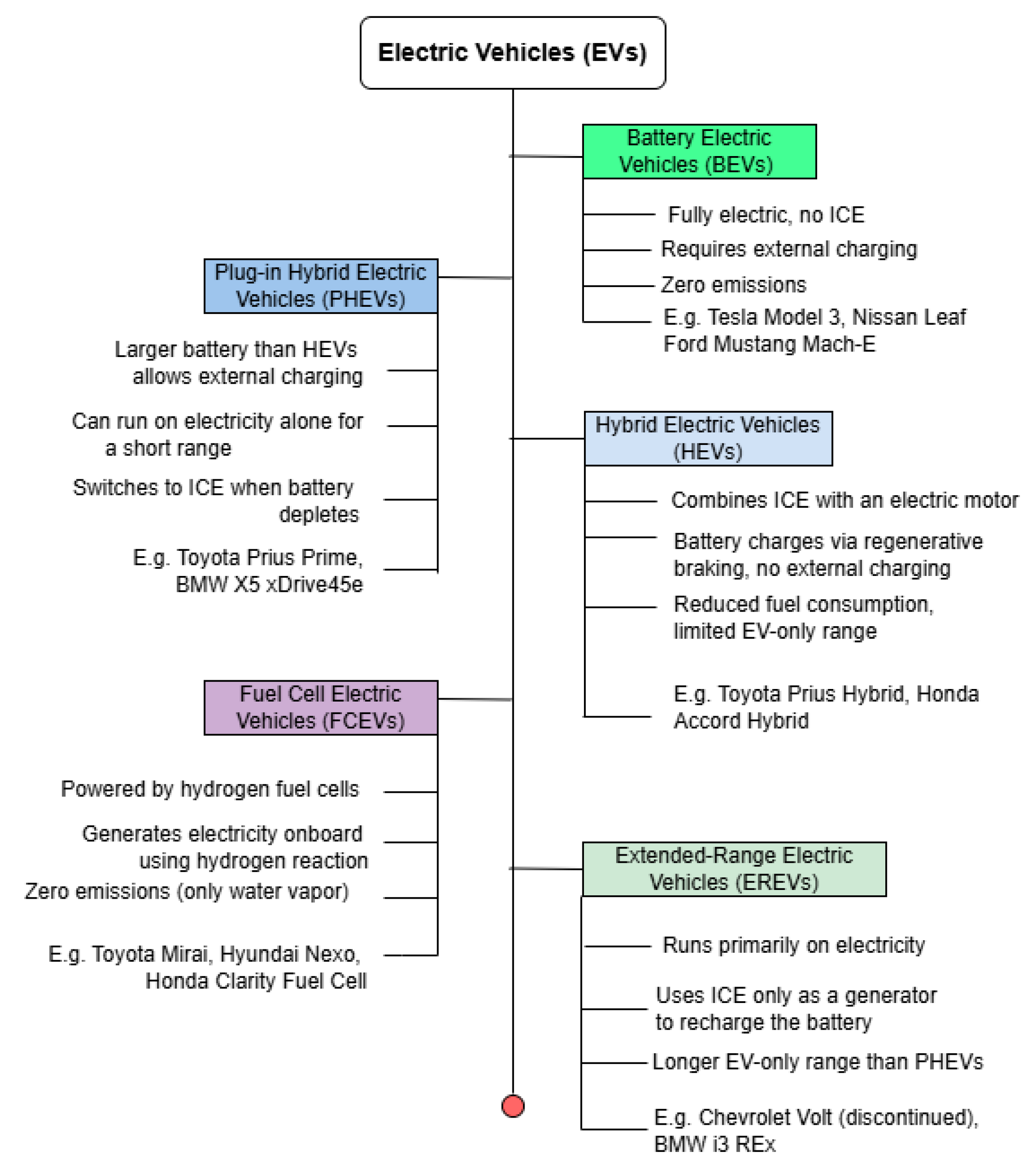
Figure 1. Trend in Electric Vehicle. This figure classifies electric vehicles (EVs) into BEVs, HEVs, PHEVs, FCEVs, and EREVs, highlighting their key features and examples.
Wevj 16 00573 g001
Figure 2. Simplified Powertrain in BEV and PHEV. This figure compares BEV and PHEV powertrains; BEVs use only a battery and electric motor, while PHEVs combine a gasoline engine with an electric motor and rechargeable battery.
Wevj 16 00573 g002
Figure 4. Some BEV Automakers and their Models.
Wevj 16 00573 g004
Figure 5. Powertrain Energy Flow.
Wevj 16 00573 g005
Figure 6. The cell electrochemical (charging and discharging) reactions.
Wevj 16 00573 g006
Figure 7. Cylindrical Lithium-Ion Cells.
Wevj 16 00573 g007
Figure 10. Heat Dissipation in Tabless 4680 Cylindrical Lithium-Ion Cells.
Wevj 16 00573 g010
Figure 11. Dimension comparison for 18650, 21700, and 4680 Cells.
Wevj 16 00573 g011
Figure 12. Tabbed and Tabless Cell Designs.
Wevj 16 00573 g012
Figure 13. Cylindrical Cells Integration into Vehicle, Reprinted from [67].
Wevj 16 00573 g013
Figure 14. Thermal Management Techniques for Cylindrical Cells.
Wevj 16 00573 g014
Figure 15. Prismatic Lithium-Ion Battery Cells.
Wevj 16 00573 g015
Figure 16. Stacked vs. Wound Prismatic Cell.
Wevj 16 00573 g016
Figure 17. The global market share of prismatic cell manufacturers, adapted from [83].
Wevj 16 00573 g017
Figure 18. BEVs Automakers using prismatic cells.
Wevj 16 00573 g018
Figure 19. Prismatic Cells Integration into Vehicle, Reprinted from [67].
Wevj 16 00573 g019
Figure 20. Typical Pouch Cells.
Wevj 16 00573 g020
Figure 21. Nissan Leaf Pouch Battery Pack, Reprinted with permission from [131].
Wevj 16 00573 g021
Figure 22. Simplified Battery Management Functions.
Wevj 16 00573 g022
Figure 23. Battery Management System Architecture.
Wevj 16 00573 g023
Figure 24. Cell Balancing (Charge Redistribution). Active balancing transfers charge from higher-SoC cells to lower-SoC cells (as can be seen, active balancing takes the average charge level), equalizing SoC while preserving energy and increasing usable capacity. Passive balancing equalizes by bleeding excess charge as heat through shunt resistors on higher-SoC cells (as can be seen, passive balancing takes the level of the lowest charge level.
Wevj 16 00573 g024
Figure 25. Schematic representation of battery State of Charge (SoC).
Wevj 16 00573 g025
Figure 26. Overview of Battery State of Charge Estimation Methods.
Wevj 16 00573 g026
Figure 28. Kalman Filtering Algorithm workflow for State of Charge (SOC) estimation.
Wevj 16 00573 g028
Figure 30. Permanent Magnet Synchronous Motors, Reprinted from [167].
Wevj 16 00573 g030
Figure 31. Schematic Diagram of the BEV Drive System.
Wevj 16 00573 g031
Figure 32. Induction Asynchronous Motor for Audi Q3, Reprinted from [171].
Wevj 16 00573 g032
Figure 33. Power electronics components in BEV.
Wevj 16 00573 g033
Figure 34. Configuration of a conventional onboard EV charger.
Wevj 16 00573 g034
Figure 35. Configuration of onboard power electronic interlinks. (a) Stand-alone onboard bidirectional chargers (b) Integrated onboard bidirectional charger.
Wevj 16 00573 g035aWevj 16 00573 g035b
Figure 36. Architecture of a bidirectional stand-alone onboard charger based on a two-stage conversion system.
Wevj 16 00573 g036
Figure 37. Energy Management System in BEV.
Wevj 16 00573 g037
Table 1. Comparison of 18650, 2170, and 4680 Cylindrical Lithium-Ion Cell Formats.
Cell FormatDimensions (mm)CapacityEnergy DensityProsCons
1865018 × 653.0–3.5 Ah (11–13 Wh)240–250 Wh/kgDecades of production maturity, robust metal casing, and excellent power capabilityLower per-cell capacity; lower pack-level volumetric efficiency
217021 × 704.8–5.0 Ah (16–18 Wh)260–300 Wh/kg50% more in capacity than 18650; fewer welds/interconnects; strong thermal performance in liquid-cooled packs [59]Still thousands of cells per pack; modest packing inefficiencies
468046 × 8025 Ah
(96–99 Wh)
270–300 Wh/kg Five times the energy of a 2170 in one casing; tabless design for low resistance and uniform thermal management; 16% range gain; 14% cell-level cost reduction [58]Larger cells are harder to cool internally. More difficult to manufacture, they require novel tabless and pack design innovations [60]
Table 2. Comparison of different Battery Management Systems.
TopologyScalabilityFault ToleranceWiring ComplexityCostTypical Use
CentralizedLimited (best for low cell counts)Low (single controller failure = full pack down)High (many sense wires to one PCB)Low (few components)Small packs (e-bikes, tools, small EVs)
ModularHigh (add modules easily)Moderate (module isolation possible)Moderate (short harness within modules and comm bus)ModerateMost modern EV packs (cars, buses)—balance of simplicity and scale
DistributedVery High (cell-level scaling)High (redundant nodes)Low for sensing (no long harness, but needs robust comm network)Higher (many small controllers)Niche (research, high-reliability systems, future advanced EVs)
Wireless (wBMS)High (modular without harness redesign)High (no single harness point of failure; mesh network)Very Low (no daisy-chain wires, only power connections)Initially higher, decreasing (savings in wiring vs. added RF cost)Emerging in new EV platforms (GM Ultium, etc.), where flexibility and weight reduction are priorities
Table 3. Automakers and their BMS features.
AutomakerModel(s)/PlatformBMS Features
BMWi3Modular design, module-level sensors, Bosch ECU, liquid cooling, range-extender integration
i4, iXLarge prismatic/pouch cells, multi-channel sensing, cloud analytics, passive balancing, predictive analytics, controlled fast charging (up to 200 kW)
VolkswagenMEB (ID.3/ID.4/etc.)Modular NXP BMS, per-module monitor ICs, master controller (CAN), supports 48–77 kWh packs, 125 kW charging, liquid-cooled thermal control
J1 (Taycan/e-tron GT)High-performance BMS, split sensing, impedance monitoring, charger pre-conditioning for peak charging, 800 V architecture
ToyotabZ4X, SolterraDenso modular BMS, dedicated cell-voltage and temperature sensors
NissanLeaf (early)Centralized modular BMS, passive air cooling, active cell balancing, charge limits, initial SOC accuracy issues, later improved via software and cooling plates
Leaf (recent), AriyaEnhanced SOC accuracy, improved thermal management, refined software
LucidAir900 V modular BMS (Formula E tech), modular sensing boards, master controller, precision voltage/temperature/impedance monitoring, active balancing, charger pre-conditioning (300 kW)
RivianR1T, R1SModular BMS, 2170 cells (Samsung), per-module monitoring, central controller, adaptive SOC algorithms, OTA updates, active thermal management, power sharing (V2L)
TeslaAll BEV modelsModular BMS with monitoring boards on each module, centralized logic, distributed arrangement, wired daisy-chain communication
Table 5. Comparison of Permanent Magnet Synchronous Motor (PMSM) vs. Induction Motor (IM) in EV Applications.
CharacteristicPMSM (Interior PM)Induction Motor (Squirrel Cage)
Peak Efficiency94–95% (very high)—excellent over broad range.88–92%—slightly lower, especially at light loads (magnetization losses).
Torque DensityHigh—magnets provide strong constant field; high low-speed torque (max torque at 0 rpm). Compact design for given power.Moderate—requires current to induce rotor field, so somewhat lower torque per weight. Good high-speed capability (no magnet saturation limits).
Thermal BehaviorOnly stator generates significant heat; easier to cool rotor. Magnets can overheat if not controlled (risk of demagnetization).Both stator and rotor generate heat (rotor I2R losses); rotor can get very hot under load. Tolerates high temperatures without permanent damage (no magnets).
Cost and MaterialsUses rare-earth magnets (Neodymium, etc.)—higher material cost and supply risk. No expensive magnets; simple construction (cast aluminum rotor in many cases). Generally lower material cost.
Control and OtherRequires careful control at high speed (field weakening to limit back EMF). Some drag torque due to magnets even when unpowered (cannot fully “freewheel”).Requires slip to produce torque; inherently freewheels with almost no resistance when not energized (good for coasting). Well-proven, simple design; slightly more complex to control vectorially due to slip dynamics.
Table 6. BEV Automakers and their power electronic implementation (information in this table is extrapolated from [16,20,32,135,168,171,174,175,176]).
Electric VehicleTraction InverterOBCDC/DCSuppliers
Tesla400 V and 800 V SiC MOSFET inverters (two-level for Model 3/Y; three-level for Plaid)11 kW single-phase bi-directional (Silicon Carbide in 2021)12 V non-isolated DC/DCTesla pioneered SiC inverters (Model 3) and integrated charger in the inverter housing. Uses Wolfspeed SiC.
General Motors (Ultium)400 V inverters with Si IGBT and SiC hybrid modules (two-level)11 kW single-phase (global) supplied by Continental/Delphi12 V and 48 V DC/DC (Bosch)Ultium Drive combines inverter and DC/DC; Ultium Charge 360 integrates OBC network. Wireless BMS coexists.
Ford (Mach-E/Lightning)400 V SiC MOSFET inverters (Magna/Ford co-developed)7.2 kW single-phase (Continental)12 V non-isolated (Bosch)Mustang Mach-E introduced Ford’s first SiC inverter; F-150 Lightning uses integrated 80 A DC/DC.
Nissan (Leaf/Ariya)400 V Si IGBT inverter (Leaf); 400 V SiC inverter (Ariya)6.6 kW single-phase (Delta Electronics)12 V non-isolated (Renesas)Ariya’s 22 kW three-phase OBC uses SiC (Mitsubishi Electric). Leaf retains legacy Si IGBT.
BMW (i3/iX/i4)400 V Si IGBT and GaN hybrid in earlier models; next-gen iX uses SiC11 kW single-phase (Bosch)12 V isolated DC/DC (ZF/Bosch)BMW integrated traction inverter and 12 V DC/DC in a single housing in iX.
Volkswagen Group (MEB)400 V Si IGBT NPC inverters (Schaeffler/Volkswagen co-developed)11 kW single-phase (BorgWarner)12 V non-isolated (Continental)Audi e-tron GT (PPE) upgraded to SiC inverters; MEB remains Si.
BYD400 V SiC inverter (BYD in-house)6.6 kW single-phase (BYD)12 V non-isolated (BYD)BYD uses integrated drive modules (“8-in-1”) combining inverter, OBC, DC/DC.
Hyundai/Kia (E-GMP)800 V SiC inverter (Hyundai Mobis)11 kW single-phase (Mitsubishi)12 V and 48 V DC/DC (Hyundai Mobis)800 V platform allows 350 kW fast charging; OBC integrated in motor housing.
Lucid Air900 V SiC inverter19.2 kW three-phase (custom)12 V isolated DC/DCLucid’s 900 V system uses ultra-fast 350 kW charging; entirely SiC at 900 V.
Rivian (R1T/R1S)400 V Si MOSFET/IGBT inverter (Bosch)11 kW single-phase (Continental)12 V non-isolated DC/DCRivian’s Drive units integrate inverter, DC/DC, and thermal management in a compact housing.
NIO (ET7, ES8)400 V SiC hybrid inverter (NIO in-house)22 kW three-phase bidirectional (Mitsubishi)12 V non-isolated DC/DCNIO’s OBC supports V2G; ET7 uses 100 kWh battery and two-speed inverter.
Table 7. Automakers’ EMS Features and Examples.
Manufacturer (Region)Key EMS/Energy FeaturesExample Models
Tesla (USA)One-pedal regen, OTA updates, battery preconditioning, heat-pump HVAC (Model S/X) [210].Model S, 3, X, Y
Nissan (Japan)e-Pedal, selectable regen, thermal management (air/liq), V2H/V2G, smart charging [211].Leaf, Ariya, Townstar EV
BMW (Germany)eDrive regen, route-based prediction, heat-pump HVAC, V2G, ISO15118 [21].i3, i4, iX, Mini Electric
Hyundai/Kia (S. Korea)Adjustable regen, heat-pump HVAC, eco modes, V2G pilot [176]Kona EV, Ioniq 5, EV6
GM (USA)Ultium regen, one-pedal, OnStar energy assist, thermal management [212].Bolt EUV, Lyriq
Ford (USA)Intelligent Range, one-pedal, heat-pump HVAC, OTA updates [135].Mach-E, F-150 Lightning
VW Group (Germany)Heat-pump HVAC, one-pedal, eco routing, V2G-ready [26].ID.4, e-tron, Enyaq
BYD (China)DiLink OTA, blade battery, V2G, battery swap [213].Han EV, Tang EV
NIO (China)Battery swap, 640 kW DC chargers, V2V/V2G, energy management [32].ES8/ES6, ET7, EC6
Disclaimer/Publisher’s Note: The statements, opinions and data contained in all publications are solely those of the individual author(s) and contributor(s) and not of MDPI and/or the editor(s). MDPI and/or the editor(s) disclaim responsibility for any injury to people or property resulting from any ideas, methods, instructions or products referred to in the content.