Abstract
Electric vehicles demand efficient and robust motor control to maximize range and performance. This paper presents an innovative adaptive fractional-order sliding mode (FO-SM) control approach tailored for Direct Torque Control with Space Vector Modulation (DTC-SVM) applied to induction motor drives. This approach tackles the challenges of parameter variations inherent in real-world applications, such as temperature changes and load fluctuations. By leveraging the inherent robustness of FO-SM and the fast dynamic response of DTC-SVM, our proposed control strategy achieves superior performance, significantly reduced torque ripple, and improved efficiency. The adaptive nature of the control system allows for real-time adjustments based on system conditions, ensuring reliable operation even in the presence of uncertainties. This research presents a significant advancement in electric vehicle propulsion systems, offering a powerful and adaptable control solution for induction motor drives. Our findings demonstrate the potential of this innovative approach to enhance the robustness and performance of electric vehicles, paving the way for a more sustainable and efficient future of transportation. In fact, the paper proposes using an adaptive approach to control the electric vehicle’s speed based on the fractional calculus of sliding mode control. The adaptive algorithm converges to the actual values of all system parameters. Moreover, the obtained performance results are reached without precise system modeling.
1. Introduction
Electric vehicles (EVs) are rapidly gaining popularity due to their environmental benefits and increasing performance. The induction motor, a robust and efficient machine, is widely used in EV propulsion systems. However, achieving optimal performance and efficiency in these systems requires advanced control strategies that can effectively handle uncertainties and parameter variations inherent in real-world applications.
Traditional control methods like proportional–integral (PI) control have been widely employed for induction motors. Still, their effectiveness is limited when dealing with the inherent nonlinearities and time-varying parameters of these systems. Factors such as changing resistances and time constants due to temperature fluctuations, aging, or varying loads significantly impact motor performance. Linear controllers like PI struggle to adapt to these dynamic changes, leading to performance degradation and issues like speed errors and ripples. This is particularly problematic in applications like electric vehicles, where precise speed and torque control are crucial for both performance and system health. Advanced nonlinear control strategies have emerged as promising alternatives to address these challenges. The literature features a diverse range of nonlinear control approaches for induction motors, including adaptive control [1,2], robust control [3,4], fuzzy logic control [5,6,7], Model Predictive Control (MPC) [8,9,10], neural networks [11,12], and sliding mode control (SMC) [13,14,15,16,17]. These advanced nonlinear control methods offer greater potential to effectively manage the complexities of induction motor systems, leading to improved performance and reliability in applications like electric vehicles, especially when faced with parameter variations caused by temperature changes, aging, or load variations.
Among the various nonlinear control techniques, SMC stands out due to its robustness against disturbances and ability to operate without requiring precise knowledge of system parameters [18,19,20,21]. However, conventional SMCs suffer from a significant drawback: chattering. This phenomenon, caused by the high switching frequency inherent in SMC, can lead to undesirable oscillations and wear and tear on actuators [22,23]. To address this issue, numerous solutions have been proposed and implemented. In fact, fractional-order sliding mode control (FO-SM) has emerged as a promising solution, offering advantages such as improved robustness, faster response, and enhanced accuracy [24,25].
Direct Torque Control with Space Vector Modulation (DTC-SVM) is a popular control technique for induction motors, known for its fast dynamic response and simplicity. However, DTC-SVM systems can suffer from torque ripple and voltage fluctuations, particularly when parameter variations occur. Existing research on DTC-SVM for EV propulsion often focuses on achieving precise torque control and minimizing torque ripple. Still, it often neglects the impact of parameter variations on system performance [26].
The adaptive fractional-order sliding mode control (AFO-SMC) leverages the inherent robustness of FO-SM and the fast dynamic response of DTC-SVM, aiming to achieve superior performance, significantly reduced torque ripple, and improved efficiency [27,28]. The adaptive nature of the control system allows for real-time adjustments based on system conditions.
This manuscript introduces a major advancement in control strategy by implementing an AFO-SMC approach, which improves upon the fixed FO-SMC used in previous work [29]. The adaptive mechanism allows real-time adjustment of system parameters, such as motor characteristics and operating conditions, ensuring enhanced robustness and performance, especially in the presence of uncertainties like parameter changes or load fluctuations. Unlike the earlier publication [29], this work incorporates dynamic parameter tuning to optimize motor drive response and robustness. The control strategy is further extended to handle a broader range of operating conditions, with detailed simulations showing the versatility of adaptive FO-SMC under varying loads, temperatures, and system dynamics. Additionally, comprehensive simulations demonstrate superior performance, including faster speed response, reduced torque ripple, and improved energy efficiency, positioning this work as a significant step forward in electric vehicle propulsion control by providing a novel and effective control solution for induction motor drives, enhancing their robustness and performance in real-world applications.
The following outlines the organization of the paper:
Section 1 introduces a comprehensive overview of the electric vehicle propulsion system, highlighting its key components and the power flow from the battery or PV system to the motor and wheels. It then introduces the concept of tractive effort and the forces it needs to overcome, including rolling resistance, aerodynamic drag, and hill-climbing force. The relationship between tractive effort, gear ratio, wheel radius, and the load torque experienced by the motor is also explained.
Section 2 provides an overview of the foundational concepts, encompassing the dynamic modeling of the induction motor using space variables and presenting equations for stator and rotor flux, current, and voltage. It also clarifies the relationship between currents and fluxes in the stator and rotor and introduces the equation describing the mechanical dynamics of the motor. The role of the slip angular reference speed in determining the stator flux reference is explained, along with a concise overview of the DTC-SVM control technique and its benefits.
The paper’s central focus, which is then elaborated upon in the following sections, lies in the novel adaptive FO-SMC control law, which incorporates a sliding function for smooth transients and fast convergence, along with an adaptive speed controller and parameter identification algorithm. The stability of the closed-loop system is rigorously proven using Lyapunov functions.
The simulation results demonstrate the efficacy of the proposed control strategy in reducing the effects of parameter variations and delivering better performance than conventional methods.
The paper concludes by highlighting the significant findings and suggesting potential avenues for future research, including real-world implementation and further investigation of the impact of fractional orders and parameter identification algorithms.
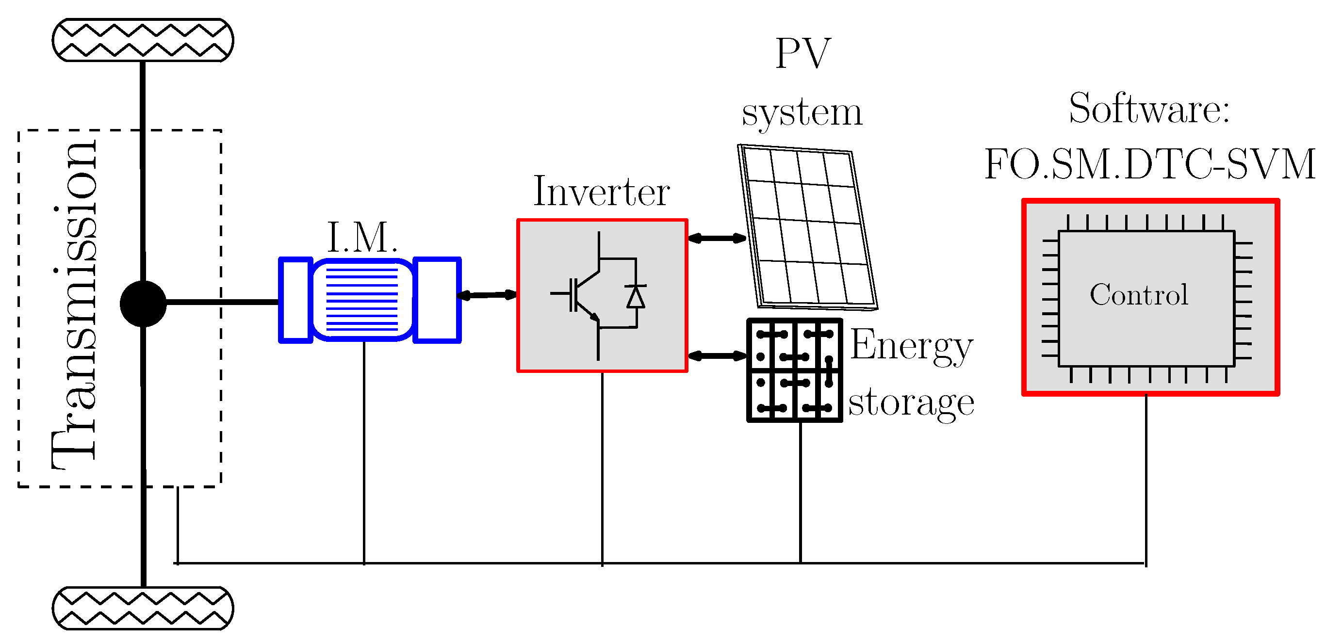
2. Fundamentals of Electric Vehicle Propulsion
Figure 1 depicts a simplified representation of an electric vehicle propulsion system, highlighting the key components involved in transforming electrical energy into mechanical motion for vehicle propulsion. The control system functions as the brain of the system, regulating the motor’s speed and torque in response to driver inputs and vehicle conditions. It employs a sophisticated FO-SM control strategy to ensure precise and efficient operation. The transmission connects the motor to the wheels, typically incorporating a gearbox to adjust the motor’s output speed and torque to match the vehicle’s requirements. The induction motor (I.M.) is the electrical motor that transforms electrical energy into mechanical energy to propel the vehicle. The inverter, an electronic device, converts the DC power from the battery or PV system into AC power suitable for driving the induction motor. The optional PV system can provide supplemental power from solar energy, contributing to the vehicle’s overall efficiency. The software represents the control algorithms and logic implemented in the control system. The FO-SM-DTC-SVM strategy is specifically mentioned, indicating a combination of advanced control techniques. The control system receives inputs from the driver (e.g., accelerator pedal) and sensors (e.g., speed sensor). Based on these inputs, it calculates the desired speed and torque for the motor. The control system then sends signals to the inverter, which adjusts the voltage and frequency of the AC power supplied to the motor. The motor generates the required torque, which is transmitted to the wheels through the transmission, propelling the vehicle. The PV system, if present, can contribute to the overall power supply, increasing efficiency.
Figure 1.
Powertrain architecture for electric vehicles: a breakdown of the key components.
To propel a vehicle forward, tractive effort is the force transmitted through the drive wheels to the ground, allowing the vehicle to both accelerate and maintain its velocity. For a vehicle moving at a velocity () and having a mass (), the tractive effort must overcome various opposing forces:
- Rolling resistance (): This force opposes the vehicle’s movement due to the deformation of the tires and the friction between them and the road. It is proportional to the vehicle’s weight and the rolling resistance coefficient (), which is typically around 0.005 for tires in electric vehicles. Minimizing this resistance is key to improving energy efficiency.
- Aerodynamic drag (): This force opposes motion as a result of air resistance. It depends on the air density (), the frontal surface area of the vehicle (A), the drag coefficient (), and the square of the vehicle’s velocity. Reducing aerodynamic drag is especially important for fuel efficiency at higher speeds.
- Hill-climbing force (): This force counters the pull of gravity when driving uphill, where represents the slope angle. Larger slopes and heavier vehicles demand greater force to overcome this resistance.
The hill-climbing force is negligible when considering a vehicle moving on a flat surface. Therefore, the tractive effort needed to maintain motion is the sum of the forces from rolling resistance and aerodynamic drag, expressed as .
The load torque () experienced by the motor is related to the tractive effort by the gear ratio (G) and wheel radius (r): , where . This can be simplified to , where and .
The connection between the motor speed () and vehicle speed can be expressed as . Substituting this into the load torque equation, we obtain , where and . This equation is used for simulating the motor’s behavior under various conditions.
3. Modeling Induction Machine with DTC-SVM
3.1. Space Vector Representation of Induction Motor Dynamics
The dynamic behavior of induction motors can be described using space vector variables as follows:
The subscripts r and s refer to the rotor and stator, respectively, while and indicate the components in the () reference frame. The symbols , i, and v stand for the flux, current, and voltage. Additionally, and represent the resistances of the rotor and stator. The machine speed, , is related to the slip speed () and the number of pole pairs ().
The following equations describe the correlations between the currents and fluxes:
The mechanical behavior of the machine can be represented by the equation below:
To calculate the reference angle for the stator flux, the slip angular reference speed , which is the output from the proposed controller, is utilized. In the reference frame (), the polar coordinates are used to determine the reference stator flux and as follows:
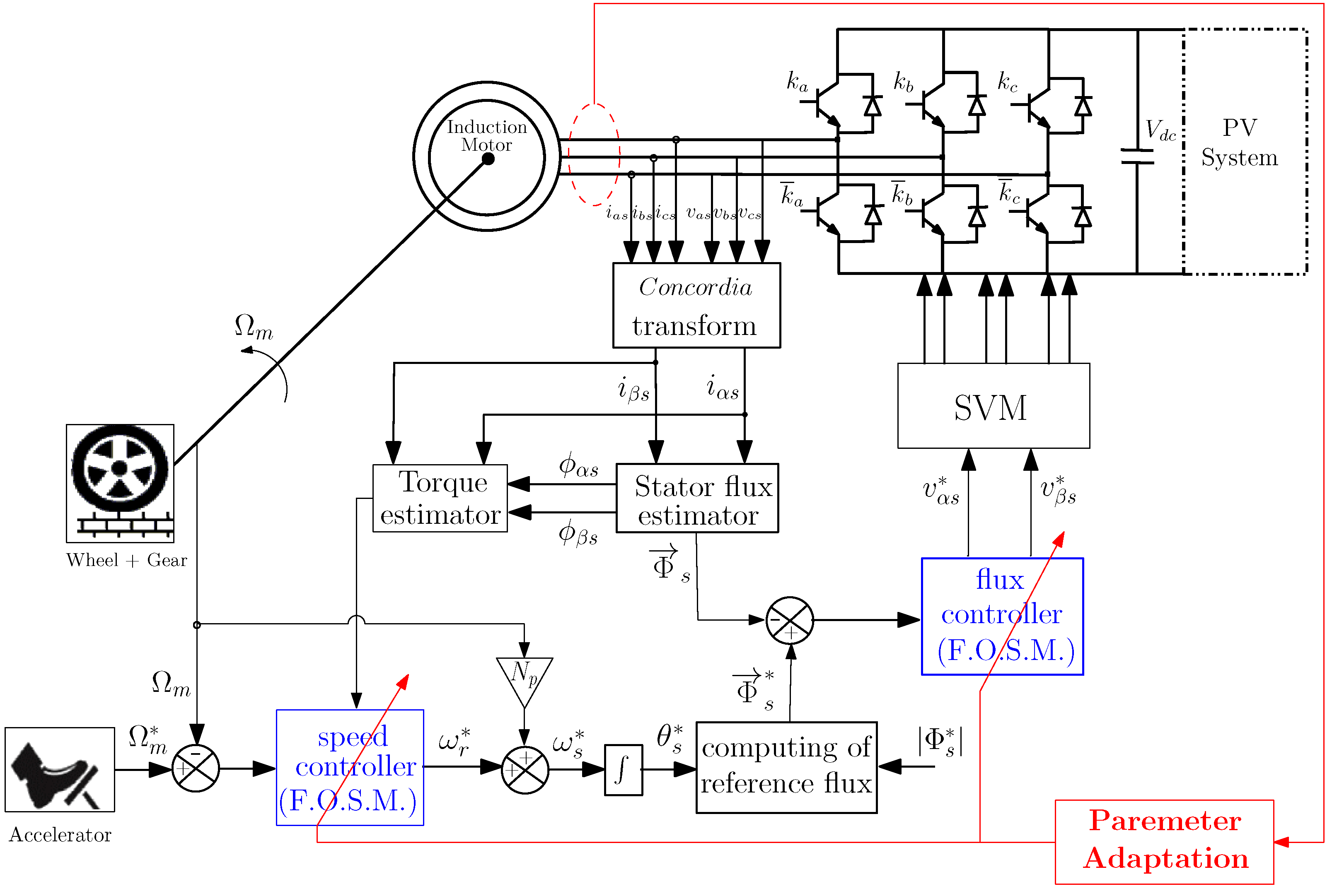
3.2. DTC-SVM Control Based on FO-SM
The primary advantages of the classic DTC approach, such as fast torque and flux control and the elimination of coordinate transformations, are preserved in the DTC-SVM block diagram. The inverter’s pulses are generated by an SVM block, which ensures a constant commutation frequency [17].
A complex control system regulating an I.M. is essential to many EVs. To keep the motor running smoothly and efficiently, the system employs an FO-SM control approach, which is a very accurate method. The system’s “speedometer”—a speed sensor—provides real-time input on the motor’s rotation. Like an automobile’s cruise control, the speed reference establishes the target speed. The speed controller employs FO-SM to assess the actual speed against the desired speed, making adjustments similar to a driver pressing the accelerator to maintain the target speed. Likewise, the torque controller utilizes FO-SM to guarantee that the motor generates sufficient power to achieve this speed, akin to how the engine propels the vehicle. The inverter receives the power from the DC bus , which a PV system guarantees. A key component in electric car battery life and performance optimization, this system is engineered to be precise and quick to respond, guaranteeing efficient and smooth motor running (Figure 2).
Figure 2.
A view from the AFO-SM-based DTC-SVM for I.M. control configuration. Adapted with permission from [29].
4. Adaptive FO-DTC-SVM Proposed Control Approach
This study introduces an innovative FO-SMC approach. Substantial modifications are made to enhance the control system’s efficiency, building upon the control law established in [30]. The sliding function is defined as outlined above to achieve smooth transients, fast convergence, and the total removal of static error. A significant aspect of this research is the demonstration of the asymptotic convergence of the proposed guidance strategy.
4.1. Adaptive Speed Controller
The speed and torque are expressed through two differential equations governed by the rotor pulsation [31,32]:
with
This gives
and then
which can be re-written as
with the vector of system parameters :
which are considered ill known and can be subject to slow changes during the system’s operation.
The sliding function employed in this study is defined as follows:
with
Let be in the interval . The vectors represent the desired trajectory. Additionally, it holds that and . The term “sign” refers to the signum function.
Assume that
and . This results:
Accordingly
Assuming that system parameter vector p is unknown. Then, an identification algorithm of this vector becomes required, and the control becomes a function of the identified parameter vector p noted :
In this case, the expression of becomes
Then, we can write that
It is obvious that
Thus
with
The update laws giving the parameters are
with for .
The control law (16) guarantees that the system’s state will converge to the sliding surface specified by .
Theorem 1.
Proof.
To begin with, we need to establish that the system state will reach the sliding surface . To achieve this, we must show that the norm of is a strictly decreasing function of time. Next, we will consider the following Lyapunov function:
Its derivative is
In fact, ill-known parameters are constant or are submitted to slow time variations in such a way that we can write , and then
Then, for :
Subsequently, when the system is maintained on the surface characterized by , this implies :
This leads to
To guarantee that the trajectory error approaches zero, we will examine the following Lyapunov function:
□
Lemma 1.
States where its fractional derivatives about time are denoted as are expressed as
4.2. Adaptive Flux Controller
The differential equation represents the flow vector controlled by the stator voltage vector :
The sliding function has to be defined:
where , and . belongs in . (, ) the desired trajectory.
The objective is to ascertain the effective control while considering that
and . This results:
Then
However, this control law depends on the parameter , which is ill-known and can vary slowly in time by increasing its temperature. For this, the control law becomes
In this case, the expression of becomes
Theorem 2.
Proof.
Initially, it is essential to establish that the trajectory of the systems must intersect the sliding surface defined by . To achieve this, we need to show that the norm of decreases strictly over time. Next, we analyze the following Lyapunov function:
Its time differential is
As described above, for slow variations of , we have and . Then, using the adaptive law (39),
for . Assuming the system is still on the surface , we can write , then
We take the following Lyapunov function into account to guarantee that the trajectory error approaches zero:
□
Lemma 2.
States where its fractional derivatives about time are denoted as are
The system assures its asymptotic stability when it converges to its predetermined trajectory.
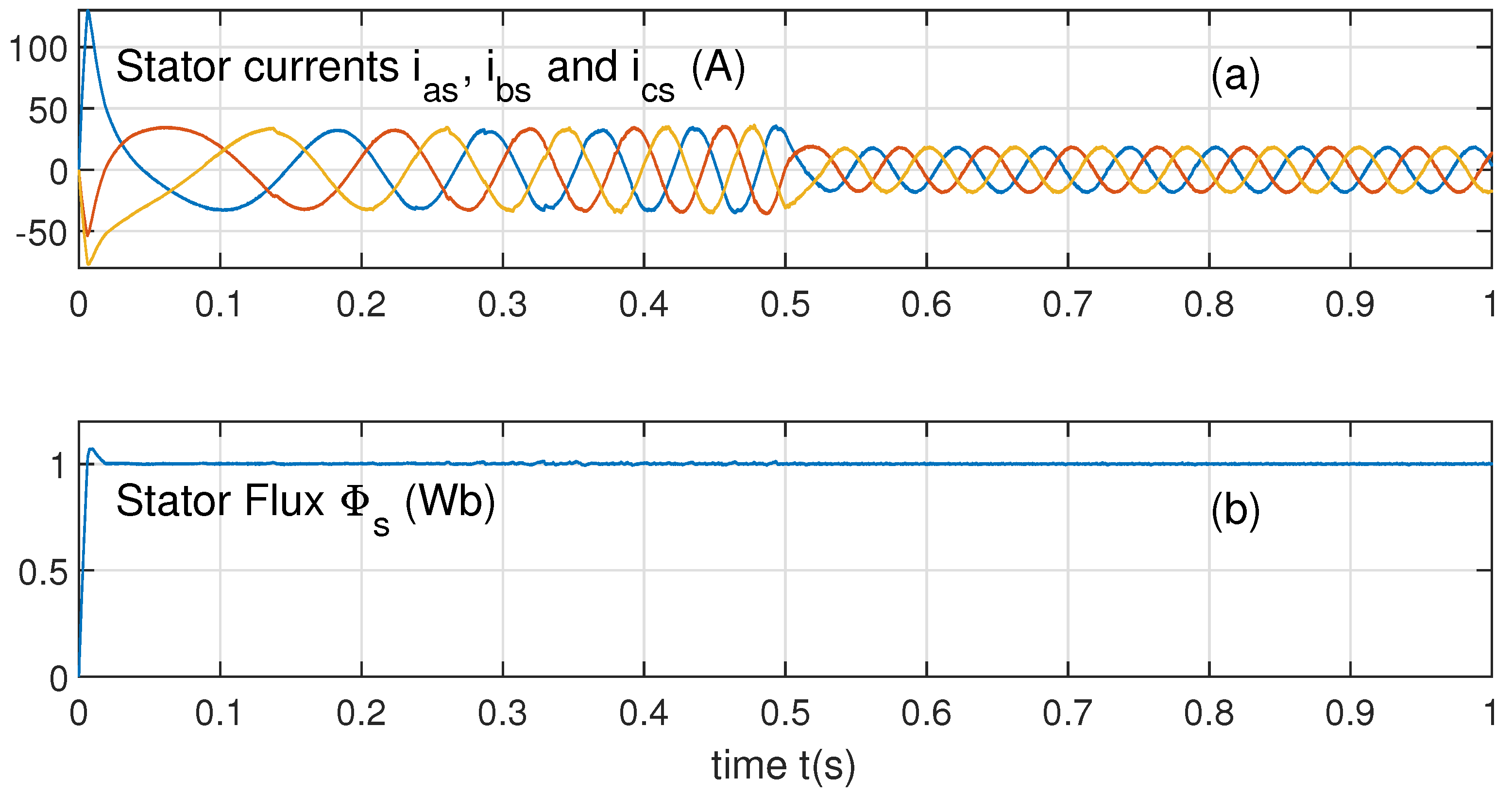
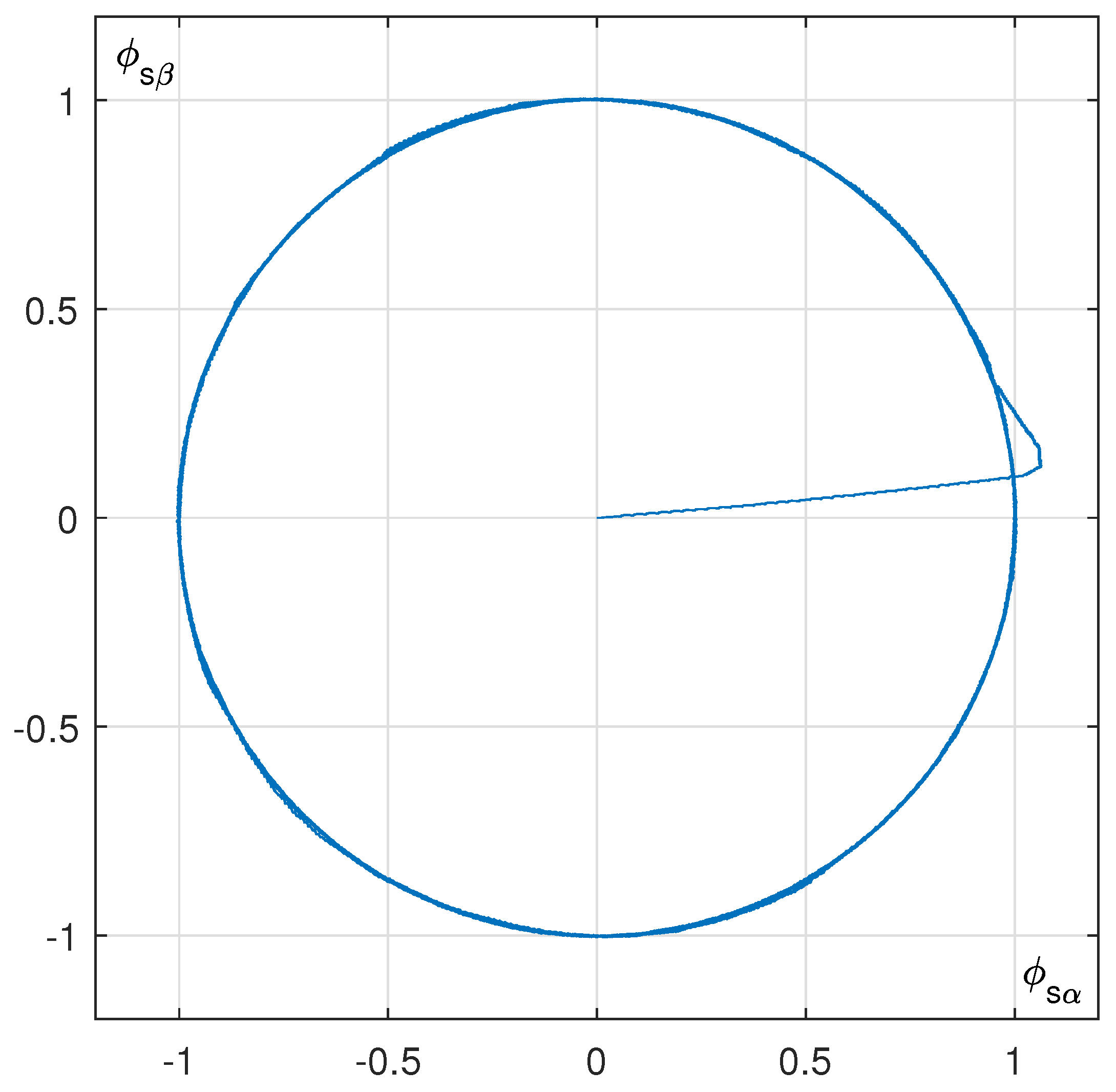
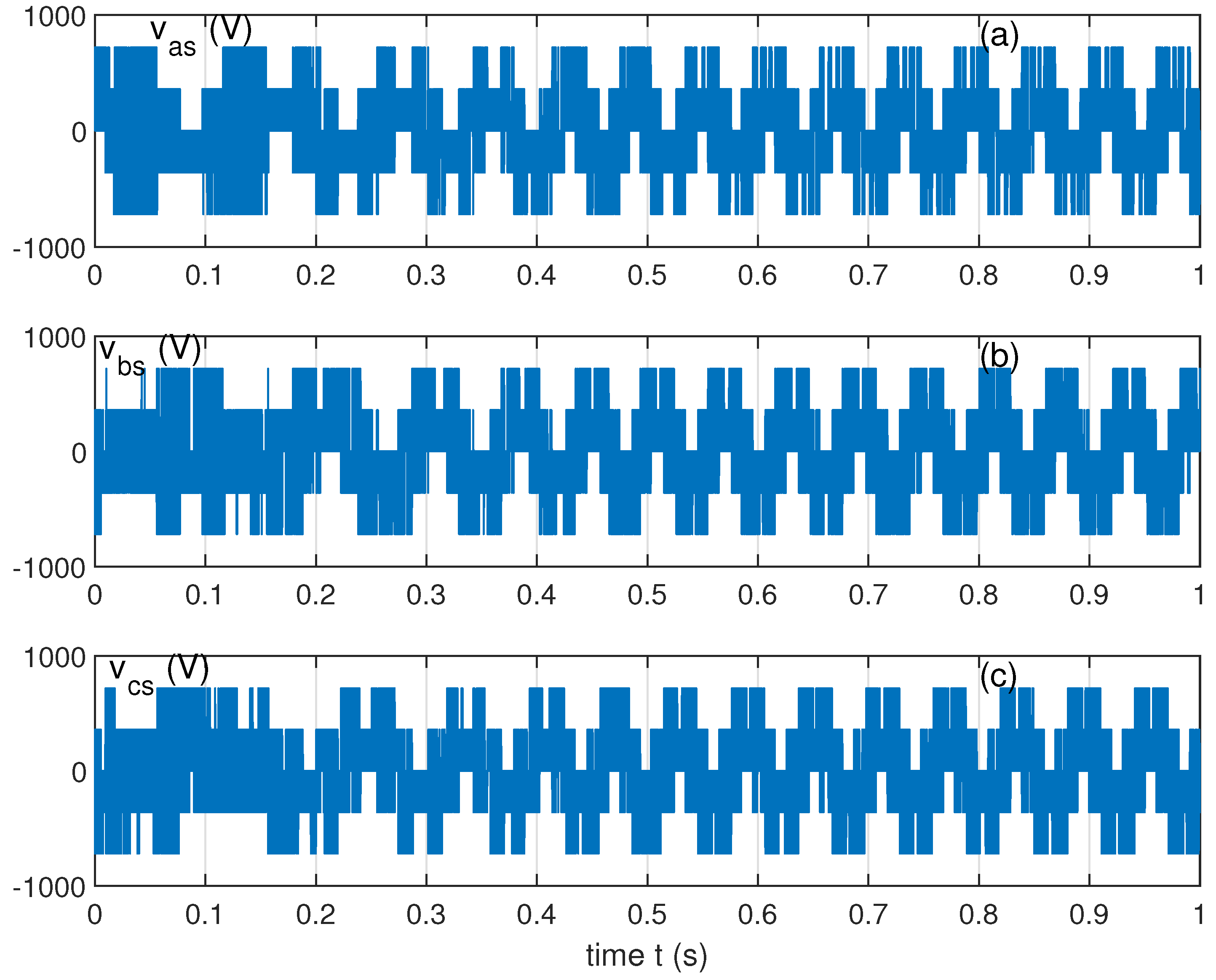
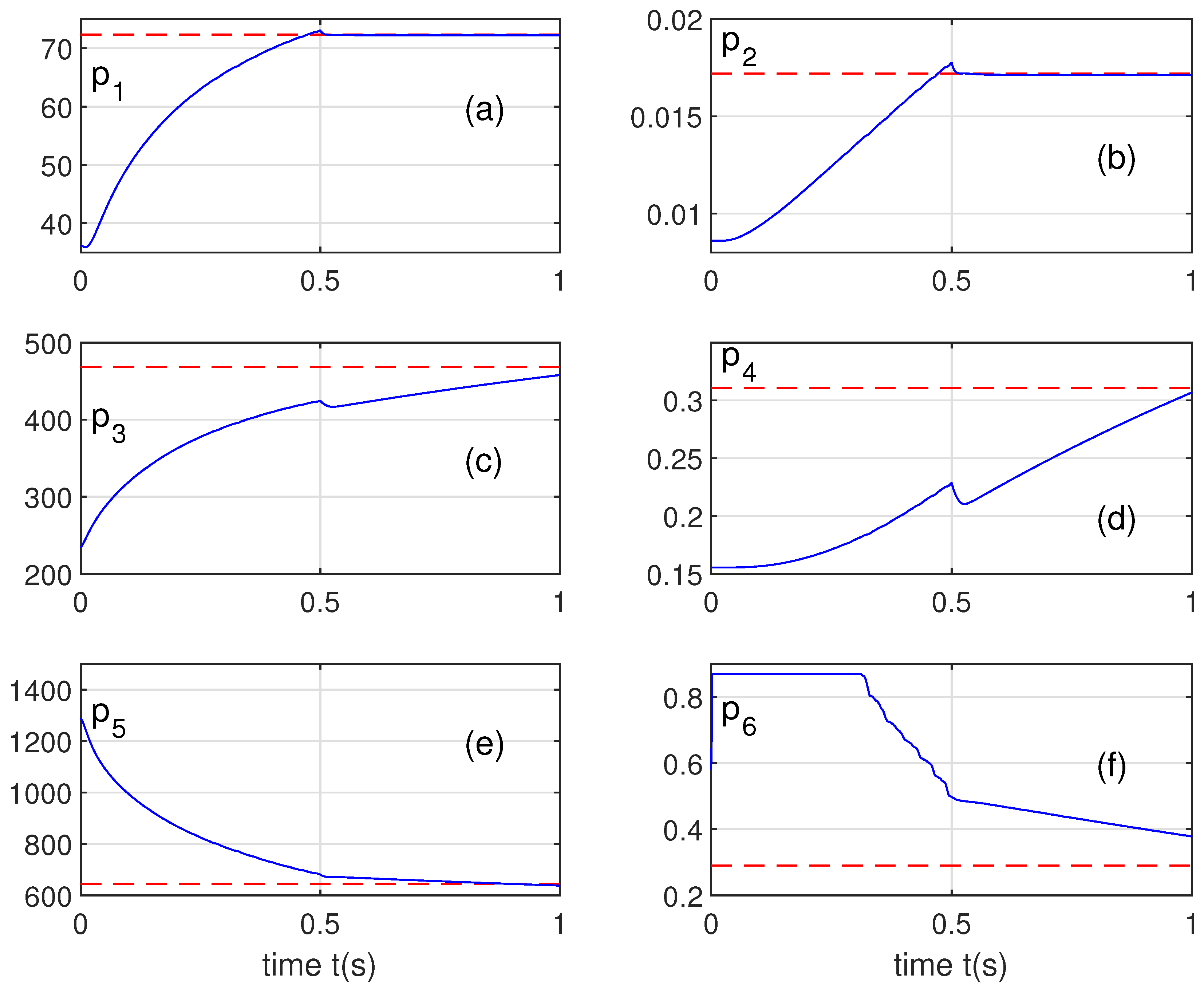
5. Simulation Results
Simulations are performed in the Matlab-Simulink environment. The initial values of parameters are taken with initial errors of , +100%, and +200%.
Figure 3, Figure 4 and Figure 5 showcase the superior performance of the Adaptive FO-SM-DTC-SVM in various aspects. Notably, it exhibits a faster and smoother speed response, significantly reduced torque ripple, a more stable and accurate flux trajectory, and a smoother and more controlled current profile. These findings highlight the effectiveness of the Adaptive FO-SM-DTC-SVM in achieving better dynamic performance, reduced torque fluctuations, improved flux control, and enhanced current waveform quality.
Figure 3.
(a) Continued line: electric vehicle speed. Dashed line: its desired trajectory. (b) Rotor pulsation. (c) Electromagnetic torque.
Figure 4.
(a) Stator currents. (b) Stator flux.
Figure 5.
The part of the stator flux defined by its part.
Figure 3a illustrates the electric vehicle’s speed progression with its desired value (in dashed line). This figure shows that the static and speed errors go to zero. It is obvious that the actual speed tracks its desired trajectory.
Figure 3b shows the evolution of the rotor pulsation control . In this application, a limitation to 0 as a minimum is applied to the control to eliminate the high-value sudden variations of the second derivatives of , representing a Dirac impulsion. This can be eliminated using a filter on the desired trajectory or elimination of the derivative term from the expression of the control because, in our case, is equal to zero, except when the slope of the desired speed changes, where it is a Dirac impulsion.
Figure 3c shows the changes in the electromagnetic torque with low ripples. From s to s, the ripples of can be calculated by
which is adequate for DTC-SVM control.
Figure 4a displays the temporal evolution of the stator currents , , and . They have adequate variations as sinusoidal shapes during steady state in the time interval [0.6, 1] s. They present low total harmonic distortions:
given that is the fundamental’s amplitude and is the harmonic’s.
Figure 4b gives the evolution in time of the stator flux. It is obvious that after 0.02 s, the stator flux keeps a constant size equal 1, with small ripples calculated as
with Wb.
In order to observe the evolution of and , Figure 5 represents the evolution of in terms of . It is clear that in the steady state, this curve is circular. and have sinusoidal shapes in the quadrature.
Figure 6 represents the evolution of the stator voltages , , and with a total harmonic distortion on the voltage equal to 0.5774 caused by the chattering on the control. These harmonics are well filtered while observing the stator current.
Figure 6.
Evolution of the stator voltages (a), (b), and (c).
Figure 7 represents the evolution of the six parameters , . These parameters converge to their actual values.
Figure 7.
Evolution of system parameters , .
Parameter has been limited to three times its actual value because, in the contrary case, the flux presents a high overshoot in its transient phase. If we reduce its maximum value, this overshoot is decreased. In Figure 5, the flux presents an overshoot equal to 7.29%.
We can reduce this overshoot or cancel it by reducing the maximum limitation of the stator resistance, for example, at two times its nominal value. However, we have chosen fact three because the stator resistance can reach three times its value at rest caused by heating the motor.
6. Conclusions
This paper delved into electric vehicle propulsion systems, focusing on the critical role of induction motor control in achieving optimal performance and efficiency. We proposed a novel adaptive FO-SMC strategy for DTC-SVM-based induction motor drives. By combining the strengths of FO-SMC and DTC-SVM, this approach successfully addressed the challenges posed by parameter variations denoted inherent in real-world applications.
The adaptive nature of the proposed control strategy, through real-time parameter adjustments based on system conditions, ensured robust and reliable operation even in the presence of uncertainties. This research demonstrated the effectiveness of the proposed FO-SMC-DTC-SVM approach through rigorous mathematical analysis and simulation results, showcasing its ability to achieve superior performance, reduced torque ripple, and improved efficiency.
Our findings pave the way for advancements in electric vehicle propulsion systems, offering a novel and effective control solution for induction motor drives. This research contributes to developing more robust and efficient electric vehicles, promoting sustainable transportation and a cleaner environment.
Author Contributions
Methodology, F.B.S. and N.D.; Software, M.T.A.; Validation, F.B.S. and N.D.; Formal analysis, M.T.A. and N.D.; Writing—review & editing, F.B.S.; Supervision, N.D.; Funding acquisition, F.B.S. All authors have read and agreed to the published version of the manuscript.
Funding
This research was funded by Prince Sattam bin Abdulaziz University, grant number PSAU/2024/01/29334.
Data Availability Statement
The original contributions presented in the study are included in the article, further inquiries can be directed to the corresponding author.
Acknowledgments
The authors extend their appreciation to Prince Sattam bin Abdulaziz University for funding this research work through the project number (PSAU/2024/01/29334).
Conflicts of Interest
The authors declare no conflict of interest.
References
- Talla, J.; Leu, V.Q.; Šmídl, V.; Peroutka, Z. Adaptive speed control of induction motor drive with inaccurate model. IEEE Trans. Ind. Electron. 2018, 65, 8532–8542. [Google Scholar] [CrossRef]
- Xu, W.; Jiang, Y.; Mu, C.; Blaabjerg, F. Improved nonlinear flux observer-based second-order SOIFO for PMSMsensorless control. IEEE Trans. Power Electron. 2019, 34, 565–579. [Google Scholar] [CrossRef]
- Wang, B.; Luo, C.; Yu, Y.; Wang, G.; Xu, D. Antidisturbance speed control for induction machine drives using high-order fast terminal slidingmode load torque observer. IEEE Trans. Power Electron. 2018, 33, 7927–7937. [Google Scholar] [CrossRef]
- Mwasilu, F.; Jung, J.-W. Enhanced fault-tolerant control of interior PMSMs based on an adaptive EKF for EV traction applications. IEEE Trans. Power Electron. 2016, 31, 5746–5758. [Google Scholar] [CrossRef]
- Du, G.; Xu, W.; Zhu, J.; Huang, N. Effects of design parameters on the multiphysics performance of high-speed permanent magnet machines. IEEE Trans. Ind. Electron. 2020, 67, 3472–3483. [Google Scholar] [CrossRef]
- Mani, P.; Rajan, R.; Shanmugam, L.; Joo, Y.H. Adaptive fractional fuzzy integral sliding mode control for PMSM model. IEEE Trans. Fuzzy Syst. 2019, 27, 1674–1686. [Google Scholar] [CrossRef]
- Xu, D.; Huang, J.; Su, X.; Shi, P. Adaptive command-filtered fuzzy backstepping control for linear inductionmotor with unknown end effect. Inf. Sci. 2019, 477, 118–131. [Google Scholar] [CrossRef]
- Ammar, A.; Benakcha, A.; Bourek, A. Adaptive MRAC-based direct torque control with SVM for sensorless induction motor using adaptive observer. Int. J. Adv. Manuf. Technol. 2017, 91, 1631–1641. [Google Scholar] [CrossRef]
- Du, H.; Chen, X.; Wen, G.; Yu, X.; Lü, J. Discrete-time fast terminal sliding mode control for permanent magnet linear motor. IEEE Trans. Ind. Electron. 2018, 65, 9916–9927. [Google Scholar] [CrossRef]
- Xu, W.; Zou, J.; Mu, C. Improved model predictive current control strategy-based rotor flux for linear inductionmachines. IEEE Trans. Appl. Supercond. 2016, 26, 0608605. [Google Scholar] [CrossRef]
- Yu, J.; Shi, P.; Dong, W.; Chen, B.; Lin, C. Neural network-based adaptive dynamic surface control for permanent magnet synchronous motors. IEEE Trans. Neural Netw. Learn. Syst. 2015, 26, 640–645. [Google Scholar] [CrossRef] [PubMed]
- Sathishkumar, H.; Parthasarathy, S. A novel neural network intelligent controller for vector controlled induction motor drive. Energy Procedia 2017, 138, 692–697. [Google Scholar] [CrossRef]
- Junejo, A.K.; Xu, W.; Hashmani, A.A.; El-Sousy, F.F.; Habib, H.U.R.; Tang, Y.; Shahab, M.B.; Keerio, M.U.; Ismail, M.M. Novel fast terminal reaching law based composite speed control of PMSM drive system. IEEE Access 2022, 10, 82202–82213. [Google Scholar] [CrossRef]
- Liu, J.; Li, H.; Deng, Y. Torque ripple minimization of PMSM based on robust ILC via adaptive sliding mode control. IEEE Trans. Power Electron. 2018, 33, 3655–3671. [Google Scholar] [CrossRef]
- Yin, Z.; Gong, L.; Du, C.; Liu, J.; Zhong, Y. Integrated position and speed loops under sliding-mode control optimized by differential evolution algorithm for PMSM drives. IEEE Trans. Power Electron. 2019, 34, 8994–9005. [Google Scholar] [CrossRef]
- Jiang, Y.; Xu, W.; Mu, C.; Liu, Y. Improved deadbeat predictive current control combined sliding mode strategy for PMSM drive system. IEEE Trans. Veh. Technol. 2018, 67, 251–263. [Google Scholar] [CrossRef]
- Salem, F.B.; Derbel, N. Second-order Sliding-mode Control Approaches to Improve Low-speed Operation of Induction Machine under Direct Torque Control. Electr. Power Components Syst. (EPCS) 2016, 44, 1969–1980. [Google Scholar] [CrossRef]
- Salem, F.B.; Derbel, N. Direct Torque Control of Induction Motors Based on Discrete Space Vector Modulation Using Adaptive Sliding Mode Control. Electr. Power Components Syst. (EPCS) 2014, 42, 1598–1610. [Google Scholar] [CrossRef]
- Mao, J.; Li, H.; Zhou, Y.; Yang, L.; Huang, J. Direct speed composite control of SPMSM drive system. IEEE J. Emerg. Sel. Top. Power Electron. 2023, 11, 5120–5130. [Google Scholar] [CrossRef]
- Zhu, W.; Li, X.; Cao, X.; Li, Y.; Zhou, K. An improved modulation strategy without current zero-crossing distortion and control method for Vienna rectifier. IEEE Trans. Power Electron. 2023, 38, 15199–15213. [Google Scholar] [CrossRef]
- Çavus, B.; Aktas, M. A New Adaptive Terminal Sliding Mode Speed Control in Flux Weakening Region for DTC Controlled Induction Motor Drive. IEEE Trans. Power Electron. 2024, 39, 449–458. [Google Scholar] [CrossRef]
- Zheng, B.-C.; Park, J.H. Slidingmode control design for linear systems subject to quantization parameter mismatch. J. Franklin Inst. 2016, 353, 37–53. [Google Scholar] [CrossRef]
- Argha, A.; Li, L.; Su, S.W.; Nguyen, H. On LMI-based sliding mode control for uncertain discrete-time systems. J. Franklin Inst. 2016, 353, 3857–3875. [Google Scholar] [CrossRef]
- Radwan, A.M.; Mahmoud, A.S.; Emira, A.; Sayed, M.A.E. Fractional-Order Sliding Mode Control; Springer: New York, NY, USA, 2018. [Google Scholar]
- Kumar, S.; Pandey, S.K.; Saxena, A.K. Fractional-Order Sliding Mode Control for Induction Motor Drives; Springer: New York, NY, USA, 2021. [Google Scholar]
- Klerk, M.L.D.; Saha, A.K. Performance analysis of DTC-SVM in a complete traction motor control mechanism for a battery electric vehicle. Heliyon 2022, 8, e09265. [Google Scholar] [CrossRef]
- Gudey, S.; Malla, M.; Jasthi, K.; Gampa, S. Direct torque control of an induction motor using fractional-order sliding mode control technique for quick response and reduced torque ripple. World Electr. Veh. J. 2023, 14, 137. [Google Scholar] [CrossRef]
- Nosheen, T.; Ali, A.; Chaudhry, M.U.; Nazarenko, D.; Shaikh, I.u.H.; Bolshev, V.; Iqbal, M.M.; Khalid, S.; Panchenko, V. A Fractional Order Controller for Sensorless Speed Control of an Induction Motor. Energies 2023, 16, 1901. [Google Scholar] [CrossRef]
- Ben Salem, F.; Turky, M.A.; Derbel, N. Enhanced Control Technique for Induction Motor Drives in Electric Vehicles: A Fractional-Order Sliding Mode Approach with DTC-SVM. Energies 2024, 17, 4340. [Google Scholar] [CrossRef]
- Qing, W.; Pan, B.; Hou, Y.; Lu, S.; Zhang, W. Fractional-Order Sliding Mode Control Method for a Class of Integer-Order Nonlinear Systems. Aerospace 2022, 9, 616. [Google Scholar] [CrossRef]
- Salem, F.B.; Masmoudi, A. A Comparative Analysis of the Inverter Switching Frequency in Takahashi DTC Strategy. Int. J. Comput. Math. Electr. Electron. Eng. (COMPEL) 2007, 26, 148–166. [Google Scholar] [CrossRef]
- Derbel, N.; Zhu, Q. Modeling, Identification and Control Methods in Renewable Energy Systems; Springer Book: New York, NY, USA, 2019. [Google Scholar]
Disclaimer/Publisher’s Note: The statements, opinions and data contained in all publications are solely those of the individual author(s) and contributor(s) and not of MDPI and/or the editor(s). MDPI and/or the editor(s) disclaim responsibility for any injury to people or property resulting from any ideas, methods, instructions or products referred to in the content. |
© 2024 by the authors. Published by MDPI on behalf of the World Electric Vehicle Association. Licensee MDPI, Basel, Switzerland. This article is an open access article distributed under the terms and conditions of the Creative Commons Attribution (CC BY) license (https://creativecommons.org/licenses/by/4.0/).