Abstract
Sensorless control of permanent magnet synchronous motors is preferable in some applications due to cost and mounting space concerns. The performance of most existing position estimation methods greatly depends on the accuracy of the motor inductance. As the estimated position should not be involved in the parameter identification process in a sensorless control system, an online inductance identification method independent of the rotor position information is developed in this paper. The proposed method utilizes the recursive least square algorithm and the particle swarm optimization algorithm to realize real-time identification of the inductance along the direct axis and the quadrature axis, respectively, based on the deduced parametric equations without position information. The proposed method is efficient enough to be implemented within 0.2 ms and does not introduce any additional signal injection. A test bench is built to validate the characteristics of the method, and the experimental results show that the identified inductance can converge to the actual value rapidly and is robust to changes in the initial values and stator current. With the proposed method, accurate estimation of the rotor position and speed can be obtained using traditional model-based position estimators, and the stability of the sensorless control system can be improved significantly.
1. Introduction
Permanent magnet synchronous motors (PMSMs) have been extensively adopted in electric vehicles in recent years due to positive features such as high efficiency, high reliability and high power density [1]. In most applications, the rotor position of the PMSM is obtained using a position sensor for precise control of the motor. However, the position sensor is eliminated in consideration of the cost, mounting space and operating environment in applications like power steering pumps and compressors in electric commercial vehicles [2,3]. And various rotor position estimation methods are substituted for position sensors under these circumstances. Equally, a sensorless control system can be used for fault-tolerant control of the traction motors in electric vehicles.
The existing rotor position estimation methods can be classified into two categories: signal injection methods and model-based methods [4]. Signal injection methods take advantage of the salient effect of PMSMs. The rotor position information can be extracted from the current response after injecting specific high-frequency voltage into the stator windings [5,6]. These methods are effective at standstill and low speeds but give bad performance as the speed increases [7]. Moreover, signal injection methods are not suitable for surface-mounted permanent magnet synchronous motors or negative-saliency permanent magnet synchronous motors. Model-based rotor position estimation methods can be further divided into back electromotive force (EMF)-based methods and active-flux-based methods [8,9]. These methods utilize a mathematical model of the PMSM to construct different kinds of position observers, such as the sliding-mode observer [10], the extended Kalman filter observer [11] and the adaptive observer [12]. The model-based methods can give precise estimation results at nominal and high speeds. And the active flux-based methods have been proved to detect the accurate rotor position at low speeds [13]. It is obvious that model-based methods are indispensable in sensorless control systems of PMSMs, and the position estimation precision greatly depends on the accuracy of the model parameters [14].
Generally, the model parameters of PMSMs refer to the winding phase resistance, the permanent magnet flux linkage and the inductance along the direct axis (d-axis) and the quadrature axis (q-axis). Though the nominal values of these four parameters are available from manufacturers or using offline parameter measurement, these parameters vary with operating environment and the conditions of the PMSMs. More specifically, the winding phase resistance and the permanent magnet flux linkage are mainly affected by the ambient temperature [15]. And variation in the inductance is attributed to the magnetic saturation effect, which is mainly caused by changes in stator current [16]. Apparently, stator current varies much more rapidly than temperature in practice, resulting in more frequent changes in inductance than in the other two parameters. Furthermore, research on parameter mismatching effects on position estimation methods indicates that the inaccuracy of the inductance is the dominant factor in position estimation errors [17]. It is suggested that an inductance lookup table should be mapped offline and stored for reliable control in applications [18]. However, offline calibration is time-consuming and difficult to implement in some situations. As a result, online inductance identification is of great importance for improving the performance of sensorless control systems.
The online inductance identification methods of PMSMs have been intensively studied in recent decades, and the related solutions include numerical methods, observer-based methods and AI-based methods [19]. Most of these methods are used for control systems with position sensors, and the sampled position information is indispensable in the identification process. In recent years, online inductance identification in sensorless control systems has attained more discussion. The traditional solution in sensorless control systems is calculating the current and voltage components in the rotating reference frame using the estimated rotor position instead of the actual rotor position. Then, the current and voltage components can be applied in the identification process [20]. Under this theory, researchers pay more attention to the problem of parameter mismatching but ignore the adverse effect on the parameter identification accuracy caused by position estimation errors. In order to realize online inductance identification independent of position information, several methods have been proposed. One effective method is obtaining the inductance from the current response under high-frequency voltage injection [21]. But the extra excitation voltage may cause torque ripples and power loss, and even not be allowed in some operating conditions [22]. The recursive least square (RLS) method is employed to identify the inductance and resistance simultaneously in [23]. A set of complicated state equations is established, and 10 intermediate variables are identified using RLS to calculate the motor parameters. Though the rotor position is not used, the method may give ill-converged results because of the rank-deficient problem. A multi-parameter identification method is proposed in [24] based on the affine projection algorithm (APA) and multiscale framework. The rank-deficient problem is solved by estimating different parameters in different timescales. However, components of the EMF in the estimated reference frame are used to develop the APA, which contains the position information. In [25], a set of polynomial equations is used to compute the initial values of the motor parameters and the rotor position numerically, while the availability in rotating conditions is not verified. Another solution for online inductance identification in a sensorless control system is state observers. For instance, the sliding-mode observer proposed in [26] can estimate the inductance and rotor position simultaneously. This method is better suited to surface-mounted PMSMs, which have equal inductance along the d-axis and q-axis, because only one parameter is treated as unknown in the observer while the others are taken as constant. Research on applications of AI-based methods in sensorless control systems is reported in [27,28]: these methods can give accurate identification results in different operating conditions but suffer from the calculation burden and a long training process.
In this paper, a novel online inductance identification method independent of the rotor position information is introduced to estimate the inductance along the d-axis and q-axis simultaneously without any extra excitation or rank-deficient problem. Compared with previous studies, the paper provides more detailed analysis of the adverse effect caused by position estimation errors in online inductance identification, drawing the conclusion that the estimated position should not be involved in the parameter identification process of PMSMs. Mathematical models of the PMSM in a stationary reference frame and rotating reference frame are utilized together to deduce parametric equations of inductance which do not contain the rotor position information. Then, the deduced equations are combined with RLS and particle swarm optimization (PSO) to give precise estimation of the inductance. With the proposed method, the estimation results on the inductance will not be affected by the accuracy of the rotor position and can converge to the accurate value rapidly, which will further improve the performance of the sensorless control system. It has to be mentioned that the proposed online inductance identification method is suitable for both surface PMSMs and interior PMSMs and can be applied along with various kinds of model-based position estimators. The proposed method can also benefit field-oriented control and fault diagnosis in various applications of PMSMs. For instance, the proposed method can be used to construct a reliable sensorless control system for traction motors in electric vehicles in case of failures of the position sensors. The effectiveness and feasibility are validated using simulations and experiments.
The rest of the paper is organized as follows. The mathematical model and sensorless control system of the PMSM are introduced in Section 2. The effect on the identification accuracy caused by position estimation errors is analyzed in Section 3. Then, the online inductance identification method independent of the rotor position is proposed in Section 4. The performance of the proposed identification method is verified using the experimental results in Section 5. Finally, the key features of the online inductance identification method are summarized in Section 6.
2. Sensorless Control Systems
2.1. Mathematical Model of PMSMs
Model-based rotor position estimation methods are usually derived from the voltage equations of PMSMs, which can be written as follows in the rotating reference frame [29].
where and are the stator voltage components, stator current components, inductance and flux linkage along the d-axis and the q-axis, is the electrical speed, is the phase winding resistance and is the differential operator. The stator flux linkage can be expressed as:
where is the permanent magnet flux linkage. In order to simplify the model of the PMSM in the stationary frame, the extended back EMF is introduced as:
Then, (1) can be rewritten as:
And (4) can be converted into the stationary reference frame as:
where , , and are the stator voltage components and stator current components in the stationary α-β reference frame, and is the difference between and . and are the α-axis and β-axis components of , which can be expressed as:
where is the electrical rotor position.
Similarly, the concept of active flux is utilized to present the mathematical model in the stationary frame in a simple form. The active flux of the PMSM is defined as [30]:
By combining (6) and (1), the model of the PMSM can be rewritten as:
Furthermore, the α-axis and β-axis components of the active flux are given as:
The stator linkage in the stationary reference frame can be obtained by associating (9) with (2), as in (10).
And (8) can be transformed into the stationary reference frame with the help of (10).
Figure 1 gives a summary of the equations above, including the extended back EMF model and the active flux model. in the diagram is the Park transformation matrix.
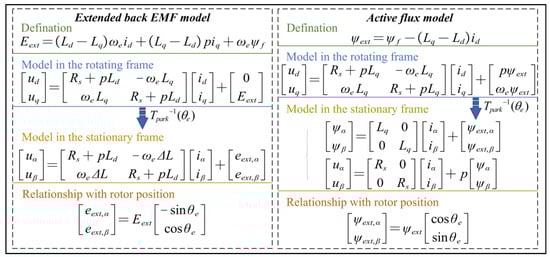
Figure 1.
Illustration diagram of the model equations used in this paper.
2.2. Rotor Position Estimator
Both the extended back EMF and the active flux in the stationary reference frame contain the information on the electrical rotor position. Equations (5) and (11) can be used to construct the back EMF observer and the flux observer, respectively. It has to be noted that the performance of the proposed online inductance identification method will not be affected by the types of used models or observers, so a simple back-EMF-based position estimator is employed in this paper [31]. The extended back EMF observer can be expressed as:
where , , and are the estimated quantities of , , and . The estimated electrical speed is regarded the actual speed, with the assumption that the error between them is sufficiently small. As the stator current components in the stationary reference frame are measured in real time using current sensors, the estimation error of and can be calculated and used as the input to a PI compensator. The PI compensator is regarded to be the substitute for the unknown extended back EMF in (12), as shown in (13).
where and are the gains of the PI compensator. With the estimated extended back EMF, the rotor position can be estimated using the arctangent function and a phase-locked loop (PLL) observer. The structure of this rotor position estimator is given in Figure 2. The estimation accuracy is affected by multiple factors, including but not limited to calculation delay, parameter mismatching, improper gains, etc. The precision of the speed estimation is assured in most position estimators, but position estimation errors seem to be inevitable under different operating environments and conditions. Though the position estimation error will not cause the sensorless control system to malfunction, the accuracy of the traditional online inductance identification will be influenced greatly, which is discussed in detail in Section 3.
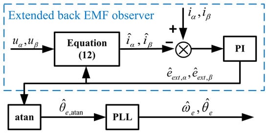
Figure 2.
Structure of the extended back-EMF-based rotor position estimator.
3. Inductance Identification Accuracy Analysis with Position Error
The RLS method with a forgetting factor is widely adopted in the research on online motor parameter identification for its simplicity [32]. The typical system in the RLS can be expressed as:
where Y and X are the output and input of the system, W is the estimated parameter matrix and k represents the number of iterations. The estimated parameter matrix can be obtained recursively as:
The voltage equations in (1) and (2) are commonly utilized to construct the estimated system. The time-derivative terms can be neglected in the steady state, and the identification systems for inductances are given as:
The above utilization of RLS is simple but effective in control systems of PMSMs with position sensors. However, the current and voltage components in the rotating reference frame will deviate from the actual values due to position estimation errors in sensorless control systems. Simulations of the above RLS identification method are executed to analyze its effect on online inductance identification. The motor parameters used in the simulations are given in Table 1. The initial values of the inductance are set to zero, and the motor operates under the rated conditions during the identification period. The online identification process is repeated, respectively, with the actual rotor position and position errors of −0.05 rad, 0.05 rad and 0.1 rad. The simulation results are shown in Figure 3a,b. It can be seen that all of the eight identification results converge to a stable value rapidly, but unbiased estimation can be realized only with the actual rotor position. The simulation results in Figure 3a show that the average relative identification error of is 0.62% compared to the actual rotor position, and increases to 11.29% with an error of −0.05 rad. And a positive position error will lead to negative relative errors, which reach −10.55% with an error of 0.05 rad and −18.04% with an error of 0.1 rad. A similar tendency can also be observed for the identification of , as shown in Figure 3b.

Table 1.
Motor parameters.
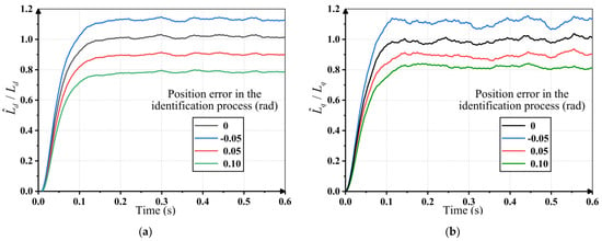
Figure 3.
Inductance identification results using RLS with different rotor position errors: (a) Identification results of d-axis inductance; (b) identification results of q-axis inductance.
4. Proposed Online Inductance Identification Method
4.1. Parametric Equation Derivation of q-Axis Inductance
The most direct approach to eliminating the effect of rotor position errors is finding parametric equations of the inductance which are independent of the position information. In consideration of the change rate and influence factors of the parameter variation, the resistance, the permanent magnet flux linkage and the rotor speed are thought to be of known quantities in the proposed inductance identification method. The estimated electrical speed is regarded the actual rotor speed. The resistance and the permanent magnet flux linkage can be obtained using offline measurement or corresponding online identification methods.
The stator current components can be given as follows in steady operating conditions.
where is the magnitude of the current vector and is the angle between the current vector and α-axis. Then, the stator linkages in the stationary reference frame can be derived by combining (9), (10) and (17).
As the angle between the current vector and d-axis can be considered constant in every identification process, and share the same angular velocity. Taking the derivative of (18), the following equation can be developed:
Then, expressions of the stator linkage are obtained by substituting (19) into (11).
Meanwhile, (10) can be rewritten as:
It is obvious that is not involved in (21). And the rotor position can be removed by calculating the quadratic sum.
Considering the algebraic property of trigonometric functions, the estimated position error will not affect the accuracy of the amplitude of the active flux linkage. It is reasonable to bring the estimated amplitude of the active flux into the identification process without worrying about the effect of position errors. The estimated amplitude is directly available in active-flux-based position estimation methods. And in the extended back-EMF-based methods, the amplitude can be acquired approximately in steady conditions using:
With the help of (20) and (22), a parametric equation of can be derived as follows.
where is the only unknown, and the other quantities can be obtained independently, as mentioned above.
4.2. Online Identification of q-Axis Inductance Using PSO
It is evident that the parametric equation in (24) is a quadratic equation of , which is not applicable in RLS identification methods. In this instance, computational-intelligence-based algorithms are widely adopted because they do not have special requirements in terms of the model structures. Among the general intelligent algorithms, PSO is noted for its simplicity and computational efficiency [33]. However, several iterations of the system model simulations are required in PSO to evaluate the candidate solutions and obtain the satisfactory one. So, most of the existing PSO-based identification methods are implemented offline [34]. Only if the simulations can be finished faster than the execution frequency of identification can online parameter identification using PSO be realized. Fortunately, the model of in (24) is quite simple. And with proper time-saving measures, it is possible to accomplish single-parameter identification in real time.
The PSO algorithm is inspired by the social intelligent behaviour of bird flocks. Assuming an m-dimensional solution space, each particle can be described by the location vector and the velocity vector , where is the sequence number, and is the sum of particles. In the k-th iteration, the locations of the particles are used to calculate fitness. According to the value of fitness, the best location of is marked as , which is also called the particle best location. And the best location in the swarm is marked as , which is also called the global best location. Then, the searching procedure can be executed by updating the velocity and the location as follows.
where is the cognitive acceleration constant and is the social acceleration constant. and are suggested to be set within , and should be less than . and are two random numbers, and is the inertia weight factor, which is a positive number less than 1 and decreasing with iterations. The process of the PSO-based parameter identification method can be illustrated as follows, with Figure 4 as a reference.
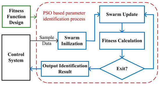
Figure 4.
Block diagram of the PSO (particle swarm optimization)-based parameter identification method.
Step 1: Design the fitness function according to the system model and collect the corresponding sample data.
Step 2: Initialize the swarm randomly and calculate the initial fitness to obtain the initial particle best location and global best location.
Step 3: Update , , and in multiple iterations until the terminate condition is satisfied. The terminate condition can be the number of iterations or the value of fitness.
Step 4: Output the value of as the identification result.
In the case of online inductance identification, the above procedures must be finished in several milliseconds or less to track the rapid variations. In consideration of the computing power of the hardware and the change rate of the inductance, the objective update frequency for the inductance in this paper is 1 kHz. The identification process will be implemented with the sampling process in parallel to the microprocessor as shown in Figure 5. It is obviously important to simplify the operations in every procedure.
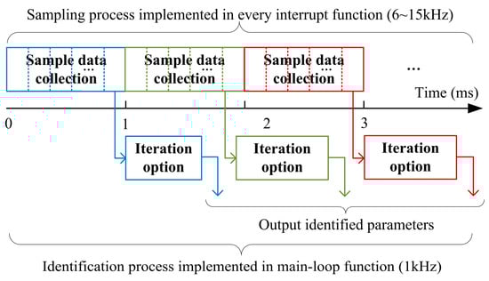
Figure 5.
Implementation of the PSO-based online inductance identification.
Firstly, the fitness function in the identification of is designed as follows according to (24).
Secondly, the sampling frequency is generally the same as the switching frequency of the converter, which is usually 6~15 kHz. That is to say, the sum of sample points is 6~15. However, the current, voltage and flux linkage of the PMSM would not vary dramatically in 1 millisecond, so it is probable that there will be similar sample data values. A pretreatment process is added to avoid repetitive operations caused by similar sample points. Specifically, if the difference in the current, voltage and flux linkage are within 1% of the rated value, these sample points will be regarded as the same.
Furthermore, the actual varying law of can offer help with accelerating the convergence velocity. The initialization of traditional PSO is completely random. However, the variation in the inductance is sequential and bounded. It is reasonable to keep the offline measurement result and the last identification result as two of the initial particle locations. And the searching range is set between 20% and 200% of the offline measurement result. Furthermore, as the inductance is negatively correlated with the stator current, the initial velocity of the particles can be set randomly as a positive value if the stator current decreases and vice versa.
All the above measures can effectively improve the efficiency of PSO, and the modified online identification process based on PSO is described in Figure 6.
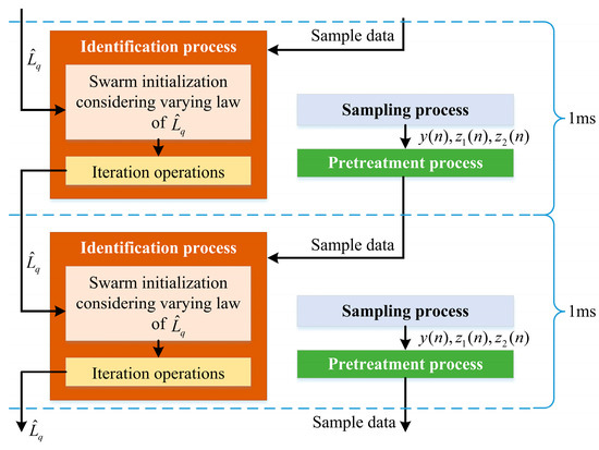
Figure 6.
Modified online identification process of with efficiency promotion measures.
Even with the modified process, it is difficult to guarantee the identification can be finished within 1 millisecond. And the most effective approach is reducing the number of particles and iterations if possible. Simulations of the online identification of with different number of particles and iterations are conducted to evaluate this issue. The number of particles is set to 10 and 20, while the number of iterations is set to 5, 10, 15 and 20, respectively. The simulation results are given in Table 2. It can be found that with more particles and iterations, more accurate and stable identification results are achieved. However, with the mentioned settings for the searching range and methods, the difference in the identification error among different iterations is not very large. More precisely, the average error of 5 iterations only increases by 2% compared with that of 20 iterations. Indeed, Figure 7 shows the identification process with different number of particles, where each identification result is obtained after five iterations. Though the identification process with 20 particles produces better results, the error with 10 particles is not unacceptable in consideration of the reduced computation burden.
Table 2.
Simulation results of the proposed PSO-based identification with 10 particles.
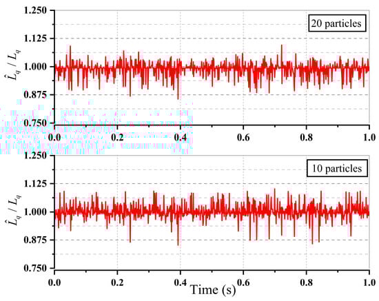
Figure 7.
Simulation results of the proposed PSO-based identification methods using different numbers of particles after five iterations.
4.3. Parametric Iquation Derivation of d-Axis Inductance
The online identification process of is independent of not only the rotor position information but also the d-axis inductance. So, it is reasonable to utilize the identification result of in the identification of . Another rotating reference frame is established based on the estimated rotor position, which is shown as the γ-δ frame in Figure 8. The mathematical model in the actual rotating reference frame can be transformed into the model in the γ-δ frame as follows:
where is the difference between the actual rotor position and the estimated rotor position, and are the voltage components and current components in the estimated rotating frame. The expression of is discretized to the following equation:
where is the sampling period, is the index of sampling instants and is the δ-axis component of the extended back EMF, . And the expression at the last instant is:
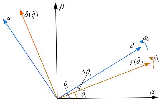
Figure 8.
Rotating reference frame based on the estimated rotor position.
Compared with the voltage and current components, the variation in the electrical speed, extended back EMF and estimated position error in two contiguous sampling periods can be neglected. Based on the above assumption, the following equation can be obtained by taking the difference between (28) and (29).
with:
Equation (31) is the parametric equation of , which is exclusive of rotor position.
4.4. Online Identification of d-Axis Inductance Using RLS
Unlike the parametric equation of , (31) is a simple linear expression. And the RLS method in Section 3 is adopted to smooth the identification results as follows:
It has to be noted that (31) is derived based on the transient model, and the update frequency of is the same as the sampling frequency, which is several times that of the update frequency of . As a result, the identification process of shares the same identification result as between each update. Furthermore, the proposed inductance identification method can be combined with various resistance and permanent flux linkage identification methods with the help of the two-timescale structure proposed in [24]. Furthermore, the identification method can be applied along with all kinds of model-based position estimators to construct the sensorless control system. The overall structure of the sensorless control system with the proposed online inductance identification method can be summarized in Figure 9. It should be noted that the resistance and permanent flux linkage used in this manuscript are obtained using offline measurement under different temperatures. The offline measurement results are made into lookup tables and applied in the inductance identification process.
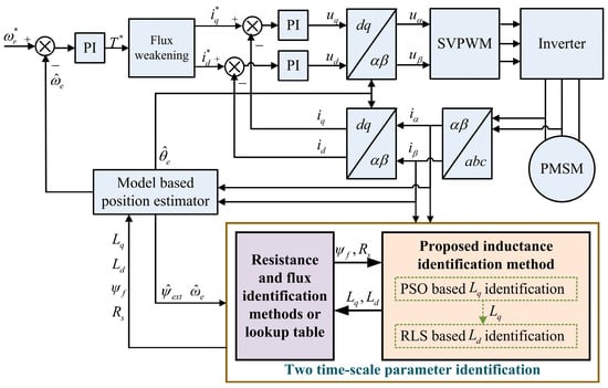
Figure 9.
The structure of the sensorless control system with online inductance identification (where * denotes the reference values).
Simulation is performed to verify the whole inductance identification method and the results are given in Figure 10. The initial value for the motor inductance is set to 60% of its actual value, which is used to realize sensorless control of the motor in the beginning. The motor operates at its rated conditions and the identification process starts at 0.2 s in Figure 10 to display the effectiveness of identification. The simulation results show that both and can converge to the actual value rapidly. The PSO-based identification of converges faster while the RLS-based identification of has better stability. The estimated speed can follow the actual speed correctly even with inaccurate inductance. However, the estimated position error decreases significantly after adopting the identified inductance, which validates the beneficial effect of the proposed method.
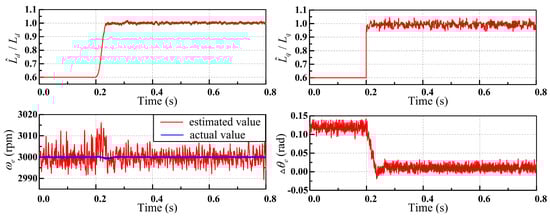
Figure 10.
Simulation results of the proposed method in sensorless control system of PMSM.
5. Experimental Results
The purpose of this section is to verify the properties of the proposed online inductance identification method in a sensorless control system of a PMSM. For the experiments, a homemade three-phase two-level IGBT inverter switching at 5~10 kHz and a DC voltage source of 540 V is applied. The MCU of the inverter is the TC234 by Infineon with a clock speed of 200 MHz. And the proposed inductance identification method is implemented with C language programming based on a product software platform offered by our cooperative enterprise. The tested motor is loaded using a homemade dynamometer. The phase current and voltage are sampled using external LEM LF 1010-S sensors, and the speed and torque of the motor are monitored using a tacho-torquemeter. All the above signals are sent to the Yokogawa WT5000 power analyzer and Yokogawa DLM3024 oscilloscope for further analysis. There is a preassembled resolver in the tested motor, the sampling result of which is sent to the MCU to validate the performance of the proposed method and can used for field-oriented control if necessary. The experimental results from the MCU, oscilloscope and power analyzer are sent to the upper computer through a CAN or Ethernet module. The experimental setup is shown in Figure 11. The parameters of the tested PMSM are the same as those in Table 1.
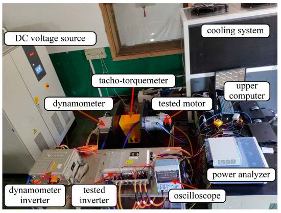
Figure 11.
The experimental setup.
5.1. Execution Time Test
The execution time is always a problem for intelligent algorithms when adopted in online identification methods. As the PSO algorithm is employed in the identification of , it is necessary to evaluate the execution time before the bench test. The RLS-based identification process will not suffer from this problem, so only the PSO-based identification process is discussed in this part. The number of sample points is set to 10, and the sample data are prestored in RAM. Then, the PSO-based identification process with different particle numbers and different iterations is executed in the TC234 once per second. The identification process is repeated at least 20 times for each group and the average execution time is calculated and recorded in Table 3.
Table 3.
Execution time of the proposed PSO-based identification in TC234 by Infineon.
As mentioned in Section 4, the expected execution frequency of the identification process in this paper is 1 kHz. It is obvious that an identification process with more than 20 particles and 20 iterations can not be accomplished every millisecond. Equally, in order not to affect the original control system, an acceptable execution time for the inductance iden-tification, which is an additional function, should be less than 20% of the total duration. After evaluation of the earlier simulation results and the test results on the execution time, 10 particles and 5 iterations are adopted in the practical applications.
5.2. Experiments under Rated Conditions
The proposed online inductance identification method is employed in the sensorless control system under rated conditions of the motor to verify its effectiveness. The identification results for inductance are adopted in the estimation of the rotor position and speed. The initial value of inductance is set as the nominal value in Table 1. Figure 12 shows the experimental results under a steady state. The identified inductance can settle around the actual value with small jitter, which is obtained using offline parameter measurements with the same currents. The maximum identification error of is 0.025 mH and the maximum identification error of is 0.045 mH, both of which are less than 10% of the actual value. With the identified inductance, the average estimation error of the rotor position is only 0.0334 rad and would not exceed 0.06 rad under a steady state. As a result, the output torque of the motor deviates from the theoretical value by about 2 N·m, which is completely acceptable in a sensorless control system.
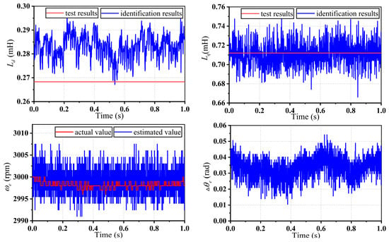
Figure 12.
Experimental results of the proposed inductance identification method under rated conditions of the motor.
5.3. Experiments with Different Initial Values
The inductance identification process is executed with different initial values to verify its convergence situation and speed. The results are given in Figure 13. The identification process starts at 0.1 s. The initial value of the inductance is set to 20%, 50%, 100%, 150% and 200% of the actual value. The identification of would not be affected by the value of , and in the experiments on identification, the value of is set to its actual value. Considering that large errors in the inductance will result in the failure of the position estimation, the actual rotor position and speed from the preassembled resolver will be used in the field-oriented control of the motor in this part.
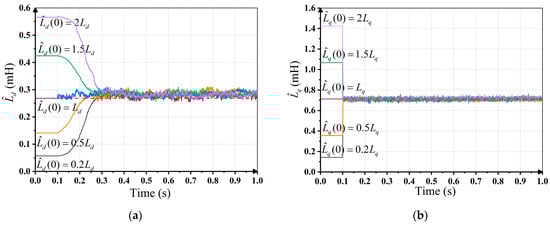
Figure 13.
Identification results with different initial values under rated conditions of the motor: (a) identification results of d-axis inductance; (b) identification results of q-axis inductance.
It can be seen from Figure 13 that all of the identification results can converge to the same value. The PSO-based identification of can converge to the actual value in the first few calculations, while the convergence time of the RLS-based identification of is about 0.15~0.2 s with different initial values, which coincides with the simulations. The maximum identification error is less than 10% of the actual value after convergence, showing a similar performance to the experiments in the previous experiments.
5.4. Experiments with Different Stator Currents
The inductance of the PMSM can change with the stator current due to self-saturation and cross-saturation effects. The experiments in Section 5.2 are repeated with different stator currents under steady states. As the tested motor runs in the torque control model, changes in current are realized by adjusting the output torque of the motor. The output torque is set between 20 N·m and 220 N·m at an interval of 20 N·m. The relationship between the output torque and stator current is given in Figure 14a. And the average value of the inductance identification results is collected in Figure 14b with the offline identification results as a reference. The offline identification results with the same current are obtained using the standstill frequency–response test, which are described as “the test results” for short in the following contents. It can be found that the identification results are quite close to the test results and the maximum relative identification error is still less than 10%. The identification results present similar changing regulation. The d-axis inductance increases with the output torque while the q-axis decrease gradually as the torque becomes larger. It can be inferred that the saturation effect along the q-axis is enhanced with the output torque. Though the weak magnetic current along the d-axis can reduce the corresponding magnetic saturation effect, the d-axis inductance becomes smaller due to the cross-saturation phenomenon.
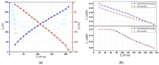
Figure 14.
Inductance identification results with different output torque: (a) corresponding relation between the output torque and the stator current; (b) inductance identification results.
In summary, the proposed online inductance identification method is independent of the rotor position information and can be completed within 200 µs in the TC234. The experimental results indicate that the online identification method can converge to the actual value rapidly under a steady state with a maximum relative identification error of 10%. The robustness of the proposed method is verified using different initial values and different stator currents. With the help of the identification results, accurate estimation of the rotor position and speed can be obtained, and the stability and reliability of the sensorless control system can be guaranteed.
6. Conclusions
A novel online inductance identification method for a PMSM is proposed in this paper, which is independent of the rotor position information. In the proposed identification method, the parametric equations for the inductance without position information are deduced, and advanced PSO and RLS are utilized to realize real-time identification of and , respectively. With the proposed method, accurate inductance identification results can be obtained and employed in the estimation of the rotor speed and position, which further improves the performance of the sensorless control system of the PMSM. The proposed method is efficient enough to be implemented within 200 µs with the help of reasonable simplification. Moreover, the proposed inductance identification method can be adopted in combination with multiple existing resistance and permanent flux linkage identification methods. All the above conclusions have been verified using simulations and experiments. Equally, the experimental results have demonstrated the robustness of the proposed method under different initial values and different stator currents. The proposed online inductance identification method can be employed in sensorless control systems of electric vehicle accessories like pumps, fans and compressors. And it is quite suitable for the fault detection and fault-tolerant control of traction motors in case of the failure of the position sensors in electric vehicles.
Author Contributions
Conceptualization, J.X. and J.Z.; methodology, J.X.; software, J.X.; validation, J.X., X.Z. and Y.X.; formal analysis, J.Z.; writing—original draft preparation, J.X.; writing—review and editing, Y.X.; supervision, J.Z.; funding acquisition, J.Z. All authors have read and agreed to the published version of the manuscript.
Funding
This research was funded by the National Key R&D Program of China sponsored by Ministry of Science and Technology of the People’s Republic of China (MoST), grant number 2022YFB25031013.
Data Availability Statement
The data that support the findings of this study are available on request from the corresponding author. The data are not publicly available due to privacy restrictions.
Conflicts of Interest
The authors declare no conflict of interest. Author Xingming Zhuang was employed by the company BIT HuaChuang Electric Vehicle Technology Co., Ltd. The remaining authors declare that the research was conducted in the absence of any commercial or financial relationships that could be construed as a potential conflict of interest.
References
- Wei, Y.; Ke, D.; Qi, H.; Wang, F.; Rodríguez, J. Multistep Predictive Current Control for Electrical Drives with Adaptive Horizons. IEEE Trans. Ind. Electron. 2024, 71, 250–260. [Google Scholar] [CrossRef]
- Singh, B.; Kashif, M. PF-MRAC-Based Elimination of Sensors in Solar-Powered PMSM Drive-Based Water Pumping System. IEEE Trans. Ind. Electron. 2023, 70, 11390–11400. [Google Scholar] [CrossRef]
- Bariša, T.; Sumina, D.; Pravica, L.; Čolović, I. Flying start and sensorless control of permanent magnet wind power generator using induced voltage measurement and phase-locked loop. Electr. Power Syst. Res. 2017, 152, 457–465. [Google Scholar] [CrossRef]
- Rafaq, M.S.; Jung, J.W. A Comprehensive Review of State-of-the-Art Parameter Estimation Techniques for Permanent Magnet Synchronous Motors in Wide Speed Range. IEEE Trans. Ind. Inform. 2020, 16, 4747–4758. [Google Scholar] [CrossRef]
- Wang, Z.; Yao, B.; Guo, L.; Jin, X.; Li, X.; Wang, H. Initial Rotor Position Detection for Permanent Magnet Synchronous Motor Based on High-Frequency Voltage Injection without Filter. World Electr. Veh. J. 2020, 11, 71. [Google Scholar] [CrossRef]
- Yoon, Y.; Sul, S.; Morimoto, S.; Ide, K. High-Bandwidth Sensorless Algorithm for AC Machines Based on Square-Wave-Type Voltage Injection. IEEE Trans. Ind. Appl. 2011, 47, 1361–1370. [Google Scholar] [CrossRef]
- Jansson, M.; Harnefors, L.; Wallmark, O.; Leksell, M. Synchronization at startup and stable rotation reversal of sensorless non-salient PMSM drives. IEEE Trans. Ind. Electron. 2006, 53, 379–387. [Google Scholar] [CrossRef]
- Kim, Y.W.; Sul, S.K. Stability Analysis of Active Front End and Permanent Magnet Synchronous Generator with Back EMF-Based Sensorless Control for DC Marine Vessels. IEEE Tran. Power Electron. 2023, 38, 5411–5421. [Google Scholar] [CrossRef]
- Boldea, I.; Paicu, M.C.; Andreescu, G.D.; Blaabjerg, F. Active Flux DTFC-SVM Sensorless Control of IPMSM. IEEE Trans. Energy Convers. 2009, 24, 314–322. [Google Scholar] [CrossRef]
- Jukić, F.; Pravica, L.; Sumina, D.; Erceg, I. Framework for Sensorless Control and Flying Start of a Permanent Magnet Generator Based on a Sliding Mode Observer. IEEE Trans. Ind. Electron. 2024, 71, 294–304. [Google Scholar] [CrossRef]
- Quang, N.K.; Hieu, N.T.; Ha, Q.P. FPGA-Based Sensorless PMSM Speed Control Using Reduced-Order Extended Kalman Filters. IEEE Trans. Ind. Electron. 2014, 61, 6574–6582. [Google Scholar] [CrossRef]
- Xu, Y.; Yao, M.; Sun, X. Overview of Position-Sensorless Technology for Permanent Magnet Synchronous Motor Systems. World Electr. Veh. J. 2023, 14, 212. [Google Scholar] [CrossRef]
- Boldea, I.; Paicu, M.C.; Andreescu, G.D. Active Flux Concept for Motion-Sensorless Unified AC Drives. IEEE Trans. Power Electron. 2008, 23, 2612–2618. [Google Scholar] [CrossRef]
- Bolognani, S.; Calligaro, S.; Petrella, R. Design Issues and Estimation Errors Analysis of Back-EMF-Based Position and Speed Observer for SPM Synchronous Motors. IEEE J. Emerg. Sel. Top. Power Electron. 2014, 2, 159–170. [Google Scholar] [CrossRef]
- Nahid-Mobarakeh, B.; Meibody-Tabar, F.; Sargos, F.M. Mechanical sensorless control of PMSM with online estimation of stator resistance. IEEE Trans. Ind. Appl. 2004, 40, 457–471. [Google Scholar] [CrossRef]
- Ahn, H.; Park, H.; Kim, C.; Lee, H. A review of state-of-the-art techniques for PMSM parameter identification. J. Electr. Eng. Technol. 2020, 15, 1177–1187. [Google Scholar] [CrossRef]
- Bolognani, S.; Ortombina, L.; Tinazzi, F.; Zigliotto, M. Model sensitivity of fundamental-frequency-based position estimators for sensorless pm and reluctance synchronous motor drives. IEEE Trans. Ind. Electron. 2018, 65, 77–85. [Google Scholar] [CrossRef]
- Wang, Q.; Zhang, G.; Wang, G.; Li, C.; Xu, D. Offline parameter self-learning method for general-purpose PMSM drives with estimation error compensation. IEEE Trans. Power Electron. 2019, 34, 11103–11115. [Google Scholar] [CrossRef]
- Filho, C.J.V.; Xiao, D.; Vieira, R.P.; Emadi, A. Observers for High-Speed Sensorless PMSM Drives: Design Methods, Tuning Challenges and Future Trends. IEEE Access 2021, 9, 56397–56415. [Google Scholar] [CrossRef]
- Huang, Y.; Zhang, J.; Chen, D.; Qi, J. Model Reference Adaptive Control of Marine Permanent Magnet Propulsion Motor Based on Parameter Identification. Electronics 2022, 11, 1012. [Google Scholar] [CrossRef]
- Wu, C.; Zhao, Y.; Sun, M. Enhancing low-speed sensorless control of PMSM using phase voltage measurements and online multiple parameter identification. IEEE Trans. Power Electron. 2020, 35, 10700–10710. [Google Scholar] [CrossRef]
- Inoue, Y.; Kawaguchi, Y.; Morimoto, S.; Sanada, M. Performance improvement of sensorless IPMSM drives in a low-speed region using online parameter identification. IEEE Trans. Ind. Appl. 2011, 47, 798–804. [Google Scholar] [CrossRef]
- Ichikawa, S.; Tomita, M.; Doki, S.; Okuma, S. Sensorless control of permanent-magnet synchronous motors using online parameter identification based on system identification theory. IEEE Trans. Ind. Electron. 2006, 53, 363–372. [Google Scholar] [CrossRef]
- Rafaq, M.S.; Mwasilu, F.; Kim, J.; Choi, H.H.; Jung, J.-W. Online parameter identification for model-based sensorless control of interior permanent magnet synchronous machine. IEEE Trans. Power Electron. 2017, 32, 4631–4643. [Google Scholar] [CrossRef]
- Colombo, L.; Corradini, M.L.; Cristofaro, A.; Ippoliti, G.; Orlando, G. An embedded strategy for online identification of PMSM parameters and sensorless control. IEEE Trans. Control Syst. Technol. 2019, 27, 2444–2452. [Google Scholar] [CrossRef]
- Ye, S.; Yao, X. A modified flux sliding-mode observer for the sensorless control of PMSMs with online stator resistance and inductance estimation. IEEE Trans. Power Electron. 2020, 35, 8652–8662. [Google Scholar] [CrossRef]
- Gwangmin, P.; Kim, G.; Gu, B. Sensorless PMSM Drive Inductance Estimation Based on a Data-Driven Approach. Electronics 2021, 10, 791–801. [Google Scholar]
- Sun, X.; Zhang, Y.; Tian, X.; Cao, J.; Zhu, J. Speed sensorless control for IPMSMs using a modified MRAS with gray wolf optimization algorithm. IEEE Trans. Transp. Electrif. 2022, 8, 1326–1337. [Google Scholar] [CrossRef]
- Foo, G.; Rahman, M.F. Sensorless Sliding-Mode MTPA Control of an IPM Synchronous Motor Drive Using a Sliding-Mode Observer and HF Signal Injection. IEEE Trans. Ind. Electron. 2010, 57, 1270–1278. [Google Scholar] [CrossRef]
- Hasegawa, M.; Matsui, K. Position sensorless control for interior permanent magnet synchronous motor using adaptive flux observer with inductance identification. IET Electr. Power Appl. 2009, 3, 209–217. [Google Scholar] [CrossRef]
- Chen, Z.; Tomita, M.; Doki, S.; Okuma, S. An extended electromotive force model for sensorless control of interior permanent magnet synchronous motors. IEEE Trans. Ind. Electron. 2003, 50, 288–295. [Google Scholar] [CrossRef]
- Zhang, J.; Peng, F.; Huang, Y.; Yao, Y.; Zhu, Z. Online Inductance Identification Using PWM Current Ripple for Position Sensorless Drive of High-Speed Surface-Mounted Permanent Magnet Synchronous Machines. IEEE Trans. Ind. Electron. 2022, 69, 12426–12436. [Google Scholar] [CrossRef]
- Li, Z.W.; Chen, D.D.; Chen, Y.; Lei, H.D.; Zhu, H.G. PMSM parameter identification based on improved PSO. J. Phys. Conf. Ser. 2021, 1754, 12235. [Google Scholar] [CrossRef]
- Liu, W.; Liu, L.; Chung, I.-Y.; Cartes, D.A. Real-time particle swarm optimization based parameter identification applied to permanent magnet synchronous machine. Appl. Soft. Comput. 2011, 11, 2556–2564. [Google Scholar] [CrossRef]
Disclaimer/Publisher’s Note: The statements, opinions and data contained in all publications are solely those of the individual author(s) and contributor(s) and not of MDPI and/or the editor(s). MDPI and/or the editor(s) disclaim responsibility for any injury to people or property resulting from any ideas, methods, instructions or products referred to in the content. |
© 2024 by the authors. Licensee MDPI, Basel, Switzerland. This article is an open access article distributed under the terms and conditions of the Creative Commons Attribution (CC BY) license (https://creativecommons.org/licenses/by/4.0/).