Article

Research on Metal and Living Foreign Object Detection Method for Electric Vehicle Wireless Charging System

1
School of Electrical Engineering, Shandong University, Jinan 250061, China
2
State Grid Fuzhou Power Supply Company, Fuzhou 350004, China
3
Shandong Provincial Key Laboratory of Biomass Gasification Technology, Energy Institute, Qilu University of Technology (Shandong Academy of Sciences), Jinan 250353, China
*
Author to whom correspondence should be addressed.
World Electr. Veh. J. 2024, 15(1), 34; https://doi.org/10.3390/wevj15010034
Submission received: 14 December 2023 / Revised: 9 January 2024 / Accepted: 10 January 2024 / Published: 22 January 2024
(This article belongs to the Special Issue Wireless Power Transfer Technology for Electric Vehicles)

Abstract

:
In the electric vehicle wireless power transmission system, the high-frequency alternating magnetic field between the transmitter and receiver can have a certain impact on the health of living organisms and may even lead to lesions. In addition, metal foreign objects in an alternating magnetic field can cause their own heating or even cause fires due to the eddy current effect, so foreign object detection is an essential function in the wireless power transmission system of electric vehicles. In order to prevent metals and living organisms from entering the charging area and causing harm to the charging system and living organisms, this paper proposes a method for detecting living organisms and metal foreign objects. Firstly, the equivalent circuits for the detection systems of the living organism foreign objects and metal foreign objects are established, respectively, and the working theory of the detection system is analyzed by deriving equations. Secondly, the comb capacitor simulation model was constructed, and the comb capacitor electrode spacing, wire thickness, and capacitor spacing were designed based on the scale factor γ to explore the effects of the height and bottom area of the living organism’s foreign object on the comb capacitor. We constructed a simulation model of the detection coil and designed the inner diameter D, the number of turns N, and the wire spacing S of the detection coil according to the scale factor β. An arrayed detection coil and comb capacitor combination mode is proposed to realize the function of the simultaneous detection of metal and living organism foreign objects, and a compensation capacitor is introduced to keep the detection system in a resonant state. Lastly, a platform for foreign object detection experiments was set up to detect metal screws and beef chunks compared to the detection area without foreign objects. Metal screws entering the detection area cause a 20% voltage drop in the detection circuit resistor, and beef chunks entering the detection area cause a 30% voltage drop in the detection circuit resistor, so the detection method is effective in detecting both metals and living organisms. The feasibility of the combined mode of arrayed detection coils and comb capacitors was verified.

1. Introduction

Wireless power transmission systems can transmit power from the grid to electrical loads without cable connections. Over the past few decades [1], the research on wireless energy transmission technology has never stopped [2,3]. Wireless power transmission technology is widely used in railway transport, medical equipment, and electric vehicles due to its convenience and low equipment loss rate [4,5,6,7]. During the wireless charging process of electric vehicles, the energy coupling region of the system may be mixed with certain metal or living organism foreign objects, and the presence of these foreign objects can affect the system transmission efficiency and power. More seriously, the eddy current effect of the metal can cause the temperature of the metal itself to rise and, in severe cases, even cause a fire. Electromagnetic radiation generated by coils causes damage to the reproductive, nervous, and immune systems of living organisms. Therefore, research on foreign body detection is particularly important. Current foreign body detection techniques include two main categories: metal foreign object detection and living organism foreign object detection [8,9,10,11,12]. Research on foreign object detection technology for living organisms is still in its infancy [13]. Most studies have also focused on the use of auxiliary sensors, such as thermal cameras, X-rays, pressure sensors, radars, and heat sensors [14,15,16]. However, these methods are difficult to integrate with magnetic couplers and are susceptible to environmental influences that can lead to false positives. In contrast, a structurally simple and cost-effective method for the foreign body detection of living organisms using comb capacitors has been proposed. In high-power wireless power transmission system applications, similar to detection coil arrays, literature [17] and literature [18] introduced a comb capacitor-based living organism detection device and analyzed and designed the comb capacitor structural parameters, capacitance spacing, and so on. According to the effect of living organisms on comb capacitors, corresponding parallel resonant circuits and integral circuits are designed for the detection of living organisms. For metal foreign object detection, detector coil arrays have received much attention due to their low cost and high integration. Most of the research on metal foreign object detection using detector coil arrays has focused on optimizing the coil array layout, eliminating detection blind zones, and improving detection reliability [19,20,21]. Literature [22] proposes an active metal foreign object detection scheme based on impedance change, which solves the problem of a passive detection scheme that cannot achieve the detection under a power-down situation by applying an excitation source to the detection coil, optimizes the coil structure to solve the problem of detecting the blind area, and selects the frequency that deviates from the resonance point with high sensitivity. In practice, spatial misalignment between electric vehicles and ground-mounted power transmitters is inevitable. In order to eliminate this misalignment effect, literature [23] proposes an FOD method based on passive sensing coils using voltage vector decomposition. A non-cooperative MOD (metal object detection) mechanism is proposed in the literature [24] to support the safe operation of WEVC (wireless electric vehicle charging) systems. We designed a unique array of sensing coils to perfectly adapt to the magnetic field characteristics of DD coils. Size-modulated patch coils were created to eliminate detection blind spots by correct polarity configuration. Due to its asymmetric topology, flexible size modulation, and proper polarity configuration, it can effectively detect metallic foreign objects anywhere in the charging area. This research paper introduces and analyzes a method for the detection of living organisms and metal foreign objects based on planar comb capacitors and detection coils. Firstly, the fundamentals of the method for detecting living organisms and metal foreign objects are analyzed separately. Secondly, the comb capacitor and detection coil structural parameters are optimized and designed with the help of a finite element simulation software, Ansys Maxwell-2022R1. Finally, a combined model of the comb capacitor and detection coil is proposed. However, considering the fabrication process, it is difficult for the comb capacitor and the detection coil to reach full resonance, so it is necessary to introduce a compensation capacitor to make the detection circuit work in resonance by matching the appropriate compensation capacitor parameters. By introducing the compensation capacitor, the variation in the impedance parameter is extended to the variation in the parameters of the whole resonant circuit, which improves the sensitivity of foreign object detection. The foreign object detection method used in this paper innovatively fuses a detection coil with a comb capacitor to achieve a system for detecting metal foreign objects and living organisms with high detection accuracy.

2. Principle Analysis of Living Organisms and Metal Foreign Object Detection Technology

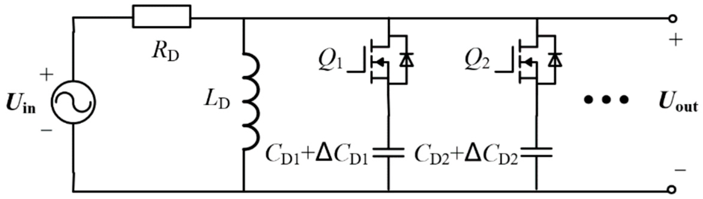
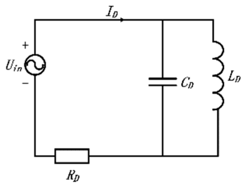
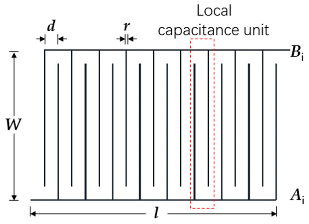
2.1. Principle Analysis of Comb Capacitor-Based Foreign Object Detection Technology for Living Organisms

When a living organism approaches the comb capacitor, the dielectric between the two pole plates of the comb capacitor as well as the capacitance to ground changes and the capacitance value changes accordingly. Thus, the presence of an organism can be demonstrated by comparing the change in the resistance voltage of the detection circuit before and after the living organism enters the detection area. Unlike the capacitors used in the literature, this paper will investigate planar comb capacitors.
The live foreign object detection circuit is shown in Figure 1, where CDi denotes the comb capacitance, ΔCDi denotes the amount of change in the comb capacitance during the invasion of the living organism foreign object, the input voltage is Uin, the external resistor is RD, and the resonance angular frequency is ω. The control switches Qi are connected to the corresponding comb capacitors, respectively. When the system charging area is free of living organisms and foreign objects, each comb capacitor CDi resonates in parallel with the inductor LD, respectively, to satisfy the parallel resonance condition shown in Equation (1). By operating the control switch Qi to ensure that only one comb capacitor is connected to the circuit at the same time, it is possible to realize the function of detecting organisms over the entire charging area when the comb capacitor is sufficient to cover the charging area.
When there is a living organism foreign object in the detection region, the equivalent resistance expression of the parallel branch composed of inductance and comb capacitance is shown in Equation (2). At this time, the output voltage is shown in Equation (3). A scaling factor γ is introduced, which is defined as the ratio of the output voltage in the presence or absence of the living organism foreign object, as shown in Equation (4). From Equation (4), the scaling factor γ is only related to the amount of change in comb capacitance ΔCDi, which is independent of the comb capacitance CDi. However, there are also live-to-ground capacitance, comb capacitance-to-ground capacitance, and the effect of energy transmitting and receiving coils and cores on comb capacitance in wireless power transmission systems. So, when designing the comb capacitor, CDi should be made as large as possible. When there is no living organism in the charging area, the inductor LD resonates in parallel with the comb capacitor CDi, and the output voltage Uout is equal to the input voltage Uin. Therefore, the scaling factor γ is proportional to the system output voltage U o u t during foreign object intrusion of living organisms. The larger the change in comb capacitance ΔCDi and the smaller the scaling factor γ, the smaller the U o u t , the larger the change in system output voltage, and the more sensitive the detection of living organisms.
ω 2 L D C D i = 1
Z s = j ω L D 1 ω 2 L D ( C D i + C D i )
U o u t = U i n 1 + J ω C D i R D
γ = U o u t U o u t = 1 1 + ω 2 R D 2 C D i 2

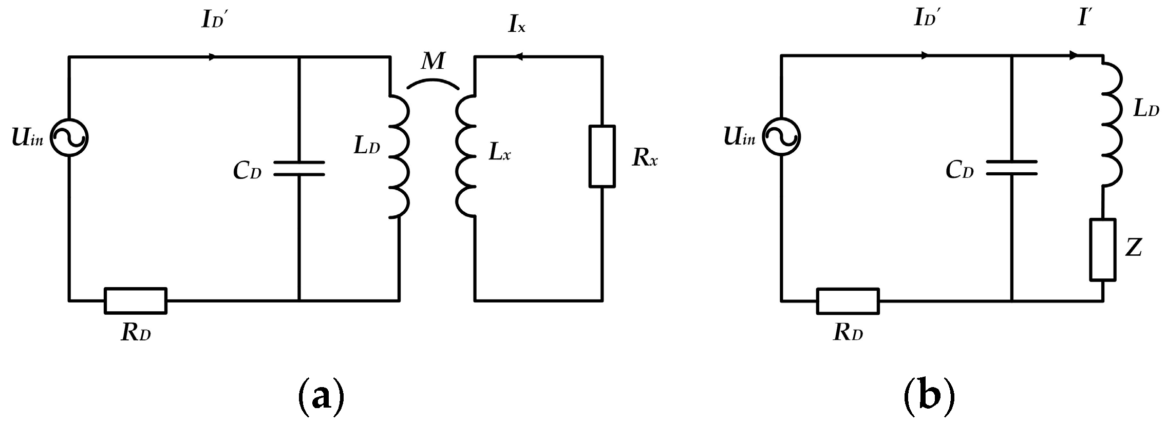
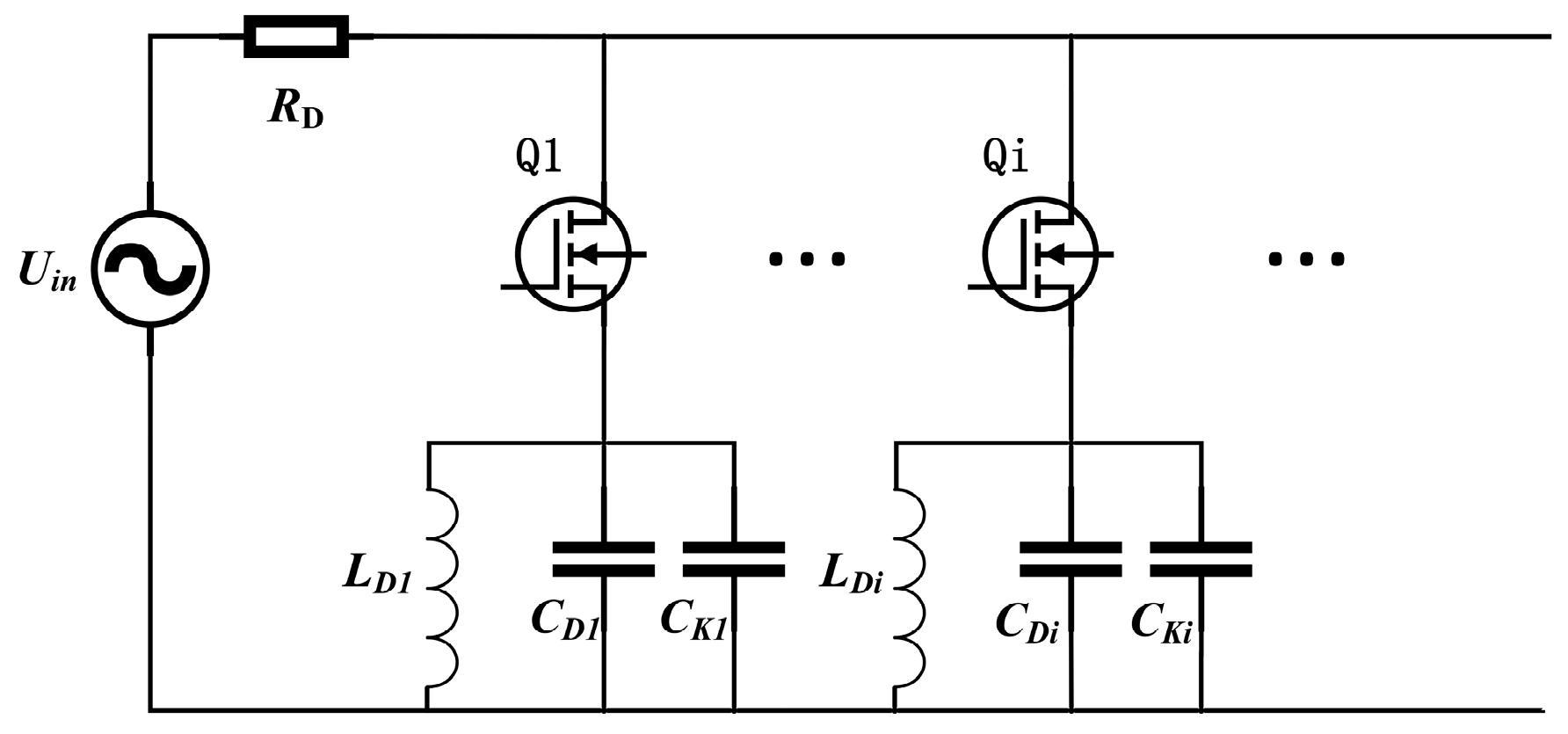
2.2. Principle Analysis of Metal Foreign Object Detection Technology Based on Detection Coil

In the alternating magnetic field, the magnetic effect or eddy current effect caused by the metal substance mistakenly entering the magnetic field will produce an additional field, this additional field will, in turn, affect the detection coil and change the impedance of the detection coil so that the detection coil voltage changes by comparing the detection coil voltage before and after the detection of metal foreign objects in the detection area to determine whether the metal foreign objects exist.
According to Faraday’s law of electromagnetic induction, the metal foreign object can be equivalently modeled as a series connection of resistance and inductance. When the detection area is free of metal foreign objects, the equivalent circuit is shown in Figure 2. Uin is the input voltage, ID is the current flowing through the sampling resistor when there are no metal foreign objects, RD is the testing resistor, LD is the measuring coil’s corresponding inductance, and CD is the parallel resonant capacitance. Since the detection coil is in resonance with the matched capacitor, the detection coil voltage is the input voltage Uin. When the detection area is mixed with metal foreign objects, the equivalent circuit diagram shown in Figure 3a,b is a simplified equivalent circuit diagram. I’D is the current flowing through the sampling resistor in the presence of metal foreign objects. I’ is the current flowing through the detection coil in the presence of metallic foreign matter. Lx is the foreign object equivalent inductance, Rx is the foreign object equivalent resistance, M is the mutual inductance between LD and Lx, and Z is the reflected impedance.
According to Kirchhoff’s voltage law, the following equation is obtained:
U i n = I D R D + ( I D I ) 1 J ω C D 0 = I Z + j ω L D + ( I I D ) 1 J ω C D
where Z = ω M 2 R x 2 + ω L x 2 ( R x J ω L x ) .
The calculation gives the detection coil voltage as follows:
U o u t = j ω L D J ( ω Z C D R D ω L D ) + Z U i n
β = U o u t U o u t = j ω L D J ( ω Z C D R D ω L D ) + Z
The circuit resonance condition is
ω 2 L D C D = 1
From Equation (6), it can be seen that when the metal foreign object enters the detection area, the voltage of the detection coil decreases, according to which it can judge whether there is a metal foreign object mixed in. As shown in Equation (7), the scale factor β is set as the ratio of the voltage of the detection coil with and without foreign objects to characterize the detection effect of the system. The smaller β indicates that the greater the change in detection coil voltage, the more effective the system detection.

3. Foreign Object Detection System Parameter Design

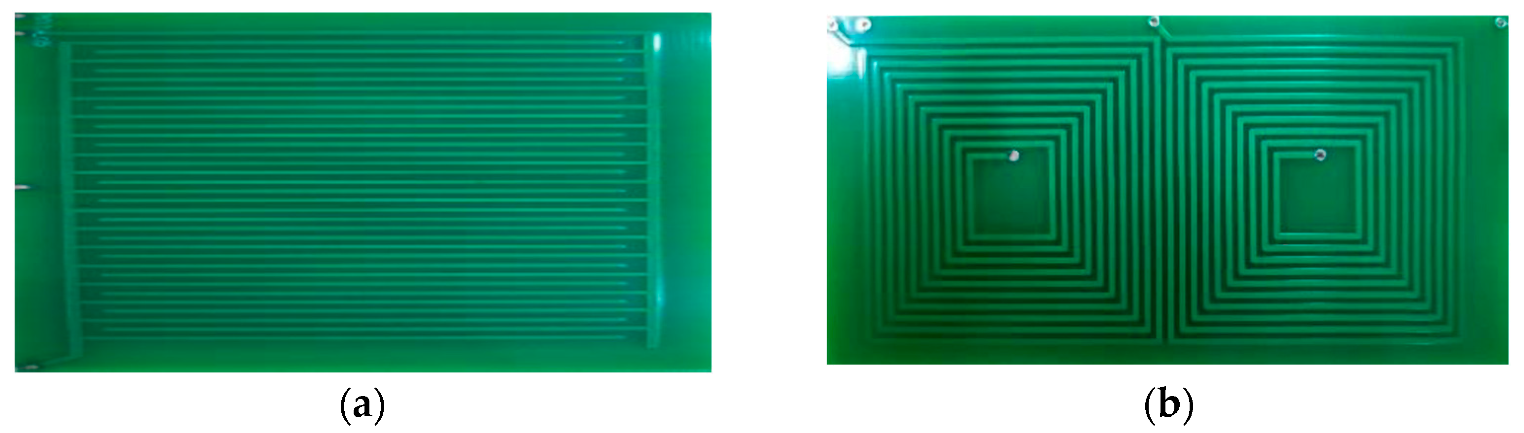
3.1. Parameter Design and Simulation Analysis of Comb Capacitor

In wireless power transmission systems, comb capacitors are generally placed on top of the energy-transmitting coils. Figure 4 shows a top view of the basic structure of a comb capacitor. A single comb capacitor consists of two comb electrodes, Ai and Bi, with the “teeth” of the comb electrodes arranged in a staggered pattern to form a local capacitance cell, where the relevant parameters are defined as length l, width w, electrode spacing d, and electrode thickness r. In this paper, the variation in comb capacitance ΔCi is taken as the reference standard, and the structural parameters of comb capacitance are optimized and designed with the help of the simulation software Ansys Maxwell-2022R1. The comb capacitance simulation model containing the living organism foreign object is shown in Figure 5, where the red part indicates the living organism foreign object, and the yellow part is the comb capacitance simulation model.
A material with a dielectric constant of 400 [25] was used for simulation and analysis in place of the living organism foreign object. The size of the living organism foreign object was chosen to be 50 × 50 × 10 mm3, and the distance of the living organism foreign object from the center of symmetry of the comb capacitor was denoted by h. The comb capacitor is set to have a length l of 100 mm, a width w of 50 mm, an electrode thickness r of 1 mm, and a wire thickness of 0.035 mm. The relationship between comb capacitance CDi and its variation ΔCDi with electrode spacing d, living organism foreign object, and comb capacitance distance h is explored, as shown in Figure 6. From Figure 6a, the smaller the electrode spacing d, the larger the comb capacitance CDi. According to Figure 6b, the comb capacitance variation ΔCDi for different electrode spacing d shows an overall decreasing trend with the increase in the distance h between the living organism foreign object and the comb capacitance. The comb capacitance change ΔCDi is significantly larger for a spacing of 3 mm compared to the case where the electrode spacing d is set to 5 mm and 7 mm. Therefore, 3 mm is selected as the comb capacitor electrode spacing in this paper.
The simulation models of different sizes of living organism foreign objects were established, respectively, to explore the effects of different sizes of living organism foreign objects on comb capacitance, as shown in Figure 7. From Figure 7, the comb capacitance change ΔCDi decreases with the increase in the distance h between the living organism foreign object and the comb capacitance for the same material and thickness. For the same distance h, the relatively large bottom area of the living organism foreign object has a greater effect on the comb capacitance.
For the purpose of analysis, the dimensions of the living organism foreign object simulation model were determined to be 50 × 50 × 10 mm3. Since this paper uses the form of PCB planar capacitors, and the common PCB lead thicknesses are 1 oz (0.035 mm) and 2 oz (0.070 mm), the thickness of the capacitor leads is determined by the simulation analysis below. Figure 8 shows the curves of the variation in comb capacitance change ΔCDi with the distance h between the living organism foreign object and the comb capacitance for different wire thicknesses. According to Figure 8, it can be stated that when a foreign object is influenced by the same live organism, the comb capacitance with 1 oz wire thickness has a greater amount of change and more significant living organism detection than the comb capacitance with 2 oz wire thickness. Therefore, in this paper, a 1 oz thickness of wire is selected.
Considering the presence of a protective enclosure in practical applications, the distance h between the living organism foreign object and the comb capacitor is set to 3 mm in the following. Since the foreign object detection area is much larger than the detection range of a single comb capacitor, the detection system should use multiple comb capacitors to detect living organisms. In this paper, comb capacitors are arrayed, and the parasitic capacitance CS between adjacent comb capacitor pole plates derived therefrom affects the normal operation of comb capacitors. Setting the spacing between two neighboring comb capacitors as g, CSCDi is used as a reference basis to explore the variation in this scaling factor with the spacing g, as shown in Figure 9. (CS is the parasitic capacitance, and ΔCDi is the comb capacitance change when h is 3 mm)
As can be seen in Figure 9, CSCDi becomes progressively smaller with increasing spacing g, and the rate of decrease is progressively retarded. It can be seen that the larger the capacitor spacing, the smaller the effect between neighboring capacitors, in line with the actual situation. The spacing g should not be too large considering the need for foreign object detection in the area between neighboring comb capacitors. Therefore, in this paper, 7 mm is selected as the spacing between two neighboring comb capacitors, when the parasitic capacitance CS is less than one-fifth of the comb capacitance variation.

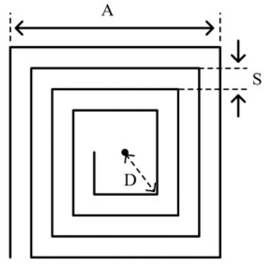
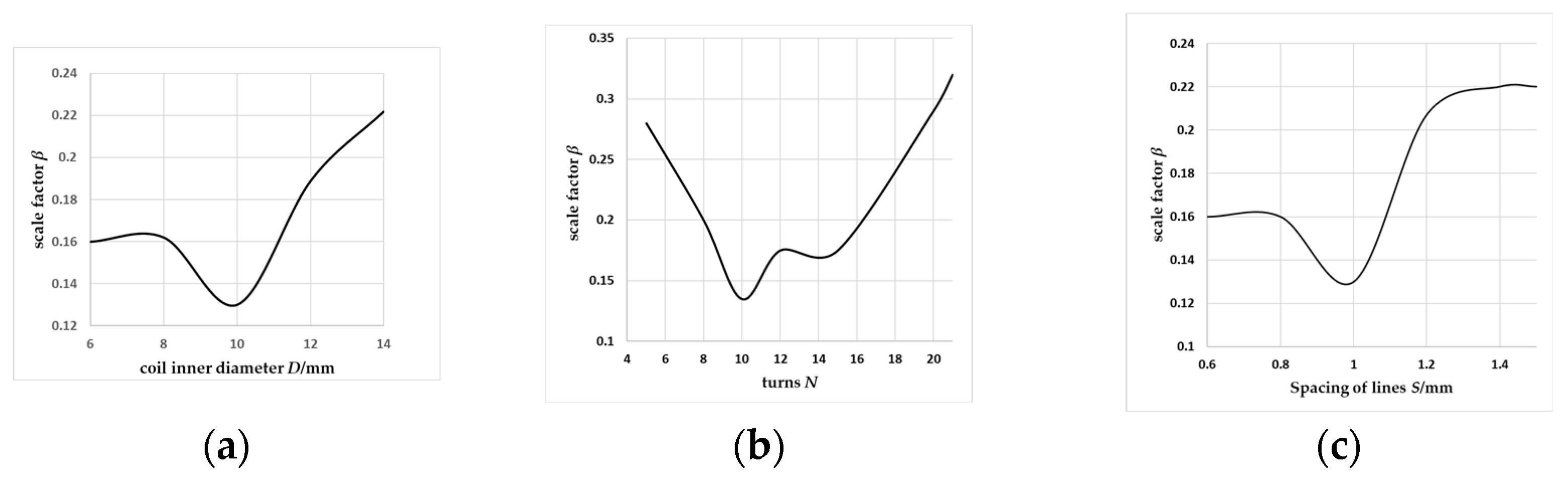
3.2. Detection Coil Parameter Design and Simulation Analysis

The detection coil is a planar square helical coil, and the coil structure is shown in Figure 10. Using Ansys Maxwell to build a simulation model, the optimization objective of the detection coil is the scaling factor β. The relationship between the coil diameter inside D, side length A, and the number of turns N and the scaling factor is investigated to find the optimal detection coil structure parameters. The scale factor β varies with coil diameter inside D, number of turns N, and wire-to-wire spacing S, as shown in Figure 11. Therefore, the selected parameters of the coil structure are coil diameter inside D = 10 mm, number of turns N = 10, and wire-to-wire spacing S = 1 mm.

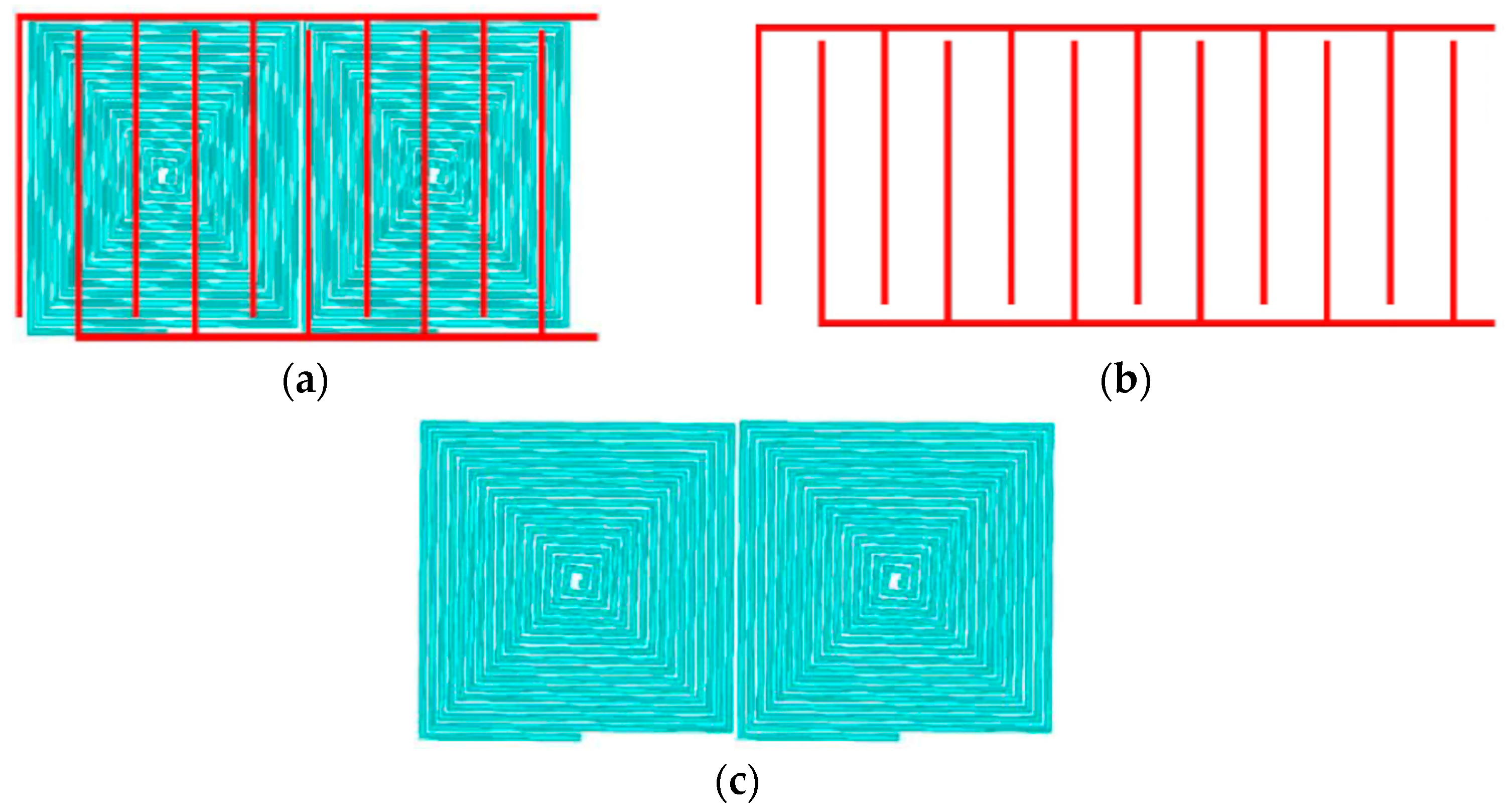
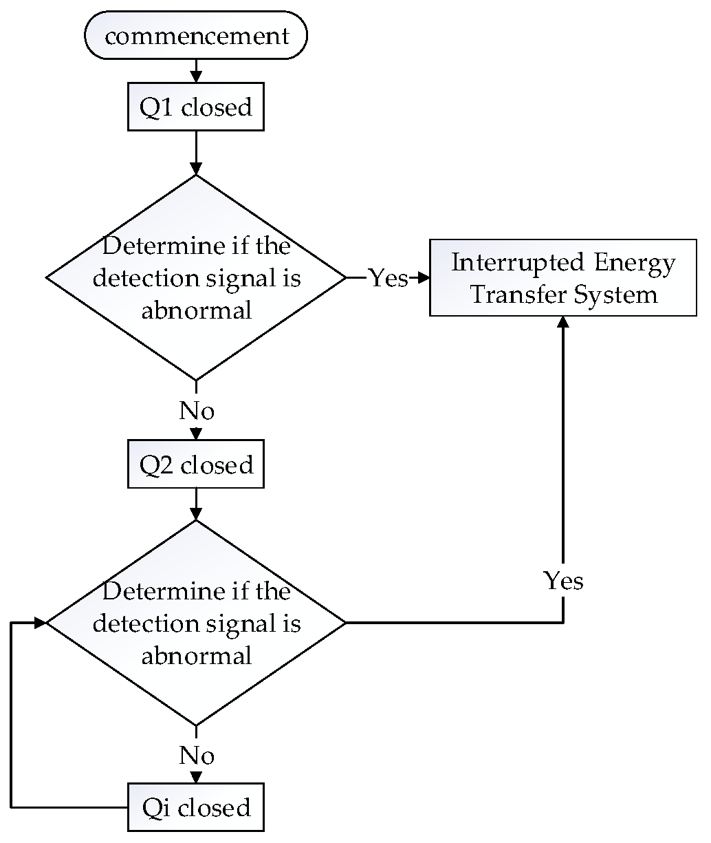
4. Combined Comb Capacitor and Detection Coil Mode

In fact, the mixing of foreign objects into the coupling region is highly random and fortuitous. In the current exploration process of domestic and international research institutes, metal foreign objects are generally equivalent to RL circuits, ignoring the weak eddy current effect that may be generated by body fluids under alternating magnetic fields, and living organism foreign objects are generally equivalent to RC circuits. However, various types of foreign objects are different in terms of material composition, shape, and structure, which makes it impossible to construct accurate circuit models of foreign objects.
In this paper, by placing arrayed detection coils overlapped with comb capacitors, it is possible to achieve the function of detecting both metal and living organism foreign objects at the same time, as shown in Figure 12. Figure 12a shows a model of the detection coil and comb capacitor combination. The red part of this is the comb capacitor model, as shown in Figure 12b. Figure 12c shows the detection coil set, which is a combination of two detection coils connected in reverse series. Since the comb capacitor detection distance is small, this paper places the comb capacitor on the front side of the PCB and the detection coil on the back side of the PCB. Figure 13 shows the foreign object detection system circuit, where LD is the array detection coil, and CDi is the comb capacitor. The circuit is compensated in parallel, with the arrayed detection coil and comb capacitor compensating each other, and the compensation capacitor CKi, which is connected in parallel with the comb capacitor, is added for adjustment so that the detection circuit is in a resonant state. The parameters of the compensation capacitor CKi are matched according to Equation (9) to ensure that the detection system works in resonance when there is no foreign object in the detection area. The detection system makes up for the previous defects that can only detect a single category of foreign objects of metal or organisms and realizes a set of detection systems that can detect both metal and organism foreign objects.
ω 2 L D i ( C D i + C k i ) = 1
Since the detection area is large, multiple groups of detection devices are required in order to achieve full-area detection. Each group of detection devices is controlled to access the detection circuit in time by switch Qi, and the detection flow is shown in Figure 14.

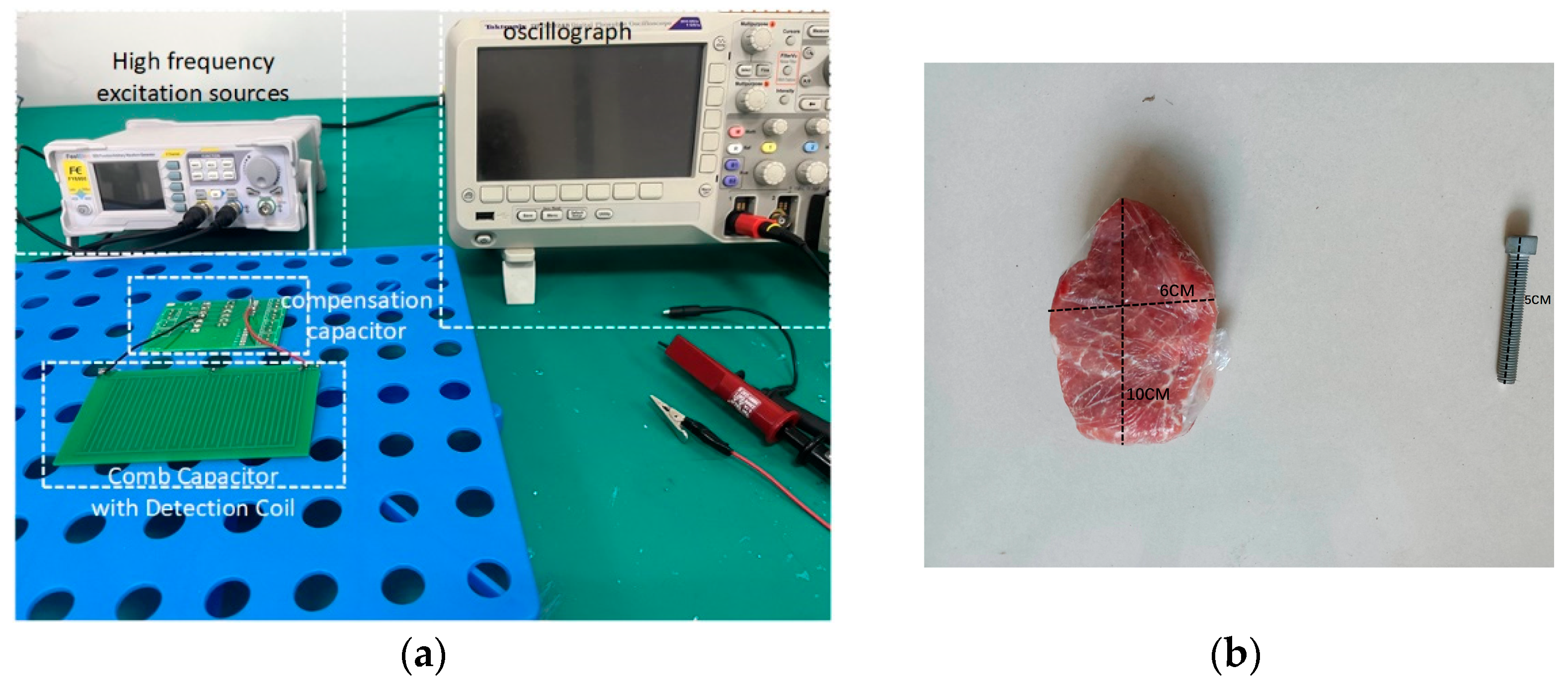
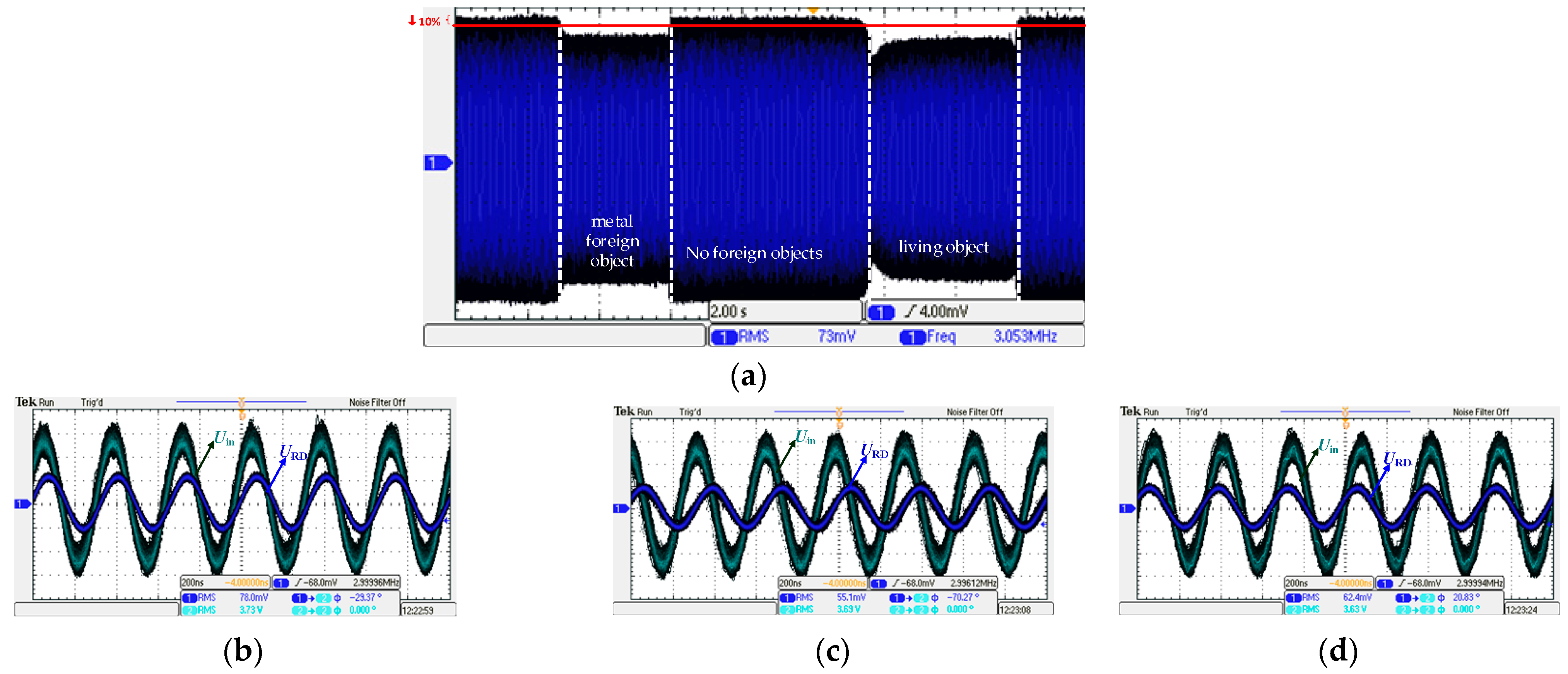
5. Foreign Object Detection System Experiment

In order to improve the sensitivity of the detection of foreign objects in the charging area, this paper adopts the way of mutual compensation between comb capacitors and detection coils and increases the compensation capacitance CKi for circuit state regulation to ensure that the detection circuit is in a resonant state.
The design of the detection coil and comb capacitor based on the optimized structural parameters described in the previous section is shown in Figure 15, with the comb capacitor on the top layer of the combination and the detection coil on the bottom layer. The structural parameters of the comb capacitor and detection coil used in this paper are shown in Table 1.
The detection coil inductance LD was measured as 8.67 μH, and the comb capacitance CD1 was 38.87 pF. The external resistor RD is selected to be 100 kΩ, an AC power signal with a frequency of 3 MHz is applied to the detection circuit, and a compensation capacitor CKi is added to the circuit to bring the circuit to a resonant state by connecting the resonant conditions in parallel. We constructed a foreign object identification experimental apparatus, as depicted in Figure 16, to confirm the viability of the foreign object detection technique suggested in this work.
The presence of foreign matter is determined by comparing the voltage change in the external resistor RD. Figure 17a shows the change in the voltage waveform of resistor RD when metals (metal screws) and living organisms (beef blocks) sequentially enter the detection area. Figure 17b–d shows the waveforms of the input voltage Uin and resistance voltage URD of the foreign object detection circuit when there is no foreign object in the detection area, when there is a beef block in the detection area, and when there is a metal screw in the detection area, respectively. It can be observed that when both metal foreign objects and living organism foreign objects enter the detection area, they both cause a change in the circuit parameters, which leads to a change in the URD. Taking the voltage amplitude change of more than 10% as the criterion for passing the test, upon analyzing Figure 17b–d, it can be found by comparison that the screws lead to an amplitude change of 20% in the resistor voltage of the detection circuit, which is a significant change in amplitude, and it is easy to achieve the effective detection of metals of this size. Testing the beef block as a biosample, as shown in Figure 16b, leads to a 30% amplitude change in the resistance amplitude of the detection circuit. Both methods caused at least a 20% change in amplitude, indicating that the detection method is highly sensitive.
In summary, it is experimentally verified that the foreign object detection method can achieve the detection of metal and living organism foreign objects with high detection sensitivity.

6. Conclusions

First, the circuit models for the detection of metal foreign objects and living organism foreign objects are established in this article. Formulas are derived in order to analyze the design concepts for the structural parameters of the comb capacitor and detection coil. Second, simulation software was used to optimize the comb capacitor’s electrode spacing and wire thickness. This study examined the impacts of a biological foreign item’s size and distance, as well as the distance between neighboring comb capacitors, on the comb capacitor. Parameters such as inner diameter, number of turns, and wire spacing of the detection coil were optimally designed. Finally, a combination model of arrayed detection coil and comb capacitor that can detect both metal and living organism foreign objects is proposed, and a compensation capacitor is introduced to improve the operation of the detection circuit and increase the sensitivity of the detection system.
The presence of metal screws and beef blocks for the detection of foreign objects in the detection area is caused by the detection circuit resistance voltage amplitude changes reduced by 20% and 30%, respectively, to achieve an effective detection of metal and living organisms foreign objects. The experimental results demonstrate the feasibility of the combined mode of detection coil and comb capacitor, which has the dual functions of metal foreign object detection and living organism foreign object detection with high detection sensitivity. The detection of multiple foreign objects of different classes in the detection area at the same time will be a potential area for future research.

Author Contributions

Conceptualization, S.C. and Z.L.; methodology, S.C. and X.L. (Xueqing Luo); software, S.C. and Z.S.; validation, S.C., Y.X. and J.W.; formal analysis, S.C., X.L. (Xianglin Li) and Q.Z.; resources, Z.L.; data curation, S.C. and S.H.; writing—original draft preparation, S.C.; writing—review and editing, S.C.; funding acquisition, Z.L. All authors have read and agreed to the published version of the manuscript.

Funding

This study was co-funded by two projects: Research and Development of Intelligent Sodium Hypochlorite Preparation and Dosing System, Project No. 2022TSGC2075; Research and Development and Application of Intelligent Energy-Saving and Environmentally Friendly Calcining Equipment, Project No. 2022TSGC2350.

Data Availability Statement

The data presented in this study are available upon request from the corresponding author. Due to the privacy of the data, the data are not shared here.

Conflicts of Interest

The authors declare no conflicts of interest. Xueqing Luo and Qingyun Zhao are employees of State Grid Fuzhou Power Supply Company. This paper reflects the views of the scientists and not the company.

References

  1. Xiang, L.; Zhu, Z.; Tian, J.; Tian, Y. Foreign Object Detection in a Wireless Power Transfer System Using Symmetrical Coil Sets. IEEE Access 2019, 7, 44622–44631. [Google Scholar] [CrossRef]
  2. Pahlavan, S.; Ashtiani, S.J. Rotation-Tolerant Wireless Power Transmission Scheme with Smart Positioning for Cognitive Research on Moving Animals. IEEE Trans. Biomed. Circuits Syst. 2023. [Google Scholar] [CrossRef] [PubMed]
  3. Pahlavan, S.; Shooshtari, M.; Maleki, M.; Ashtiani, S.J. Using Overlapped Resonators in Wireless Power Transfer for Uniform Electromagnetic Field and Removing Blank Spots in Free Moving Applications. Electronics 2022, 11, 1204. [Google Scholar] [CrossRef]
  4. Wang, Y. Development Status and Application of Wireless Charging System for Electric Vehicles. Pract. Automot. Technol. 2023, 48, 6–14. [Google Scholar]
  5. Zhang, X.; Fu, Z.; Xue, M.; Ren, N.; Wang, F. Method of detecting metal foreign object in arrayed differential coil for wireless energy transmission. New Technol. Electr. Energy Electr. 2020, 39, 9–17. [Google Scholar]
  6. Du, K.; Zhu, G.; Lu, J.; Pang, M. Detection method of metal foreign object in wireless charging system of electric vehicle. J. Zhejiang Univ. 2022, 56, 56–62, 74. [Google Scholar]
  7. Zhou, Z.; Zhai, Z. Power Loss Based Detection of Metal Foreign Objects in LCC Wireless Energy Transmission System. Electron. Prod. 2022, 30, 18–22. [Google Scholar]
  8. Sun, Y.; Wei, G.; Qian, K.; He, P.; Zhu, C.; Song, K. A Foreign Object Detection Method Based on Variation of Quality Factor of Detection Coil at Multi-frequency. In Proceedings of the 2021 IEEE 12th Energy Conversion Congress & Exposition—Asia (ECCE-Asia), Singapore, 24–27 May 2021; pp. 1578–1582. [Google Scholar]
  9. Wang, J.; Gao, J.; Yang, A.; Zhou, J. Impedance Identification-Based Foreign Object Detection for Wireless Power Transfer System. In Proceedings of the 2022 IEEE 31st International Symposium on Industrial Electronics (ISIE), Anchorage, AK, USA, 1–3 June 2022; pp. 895–898. [Google Scholar]
  10. Su, Y.; Hou, X.; Dai, X. A Review of Foreign Object Detection Techniques for Magnetically Coupled Wireless Energy Transmission Systems. Chin. J. Electr. Eng. 2021, 41, 715–728. [Google Scholar]
  11. Zhang, X.; Xing, Z.; Xue, M.; Yang, Q.; Sun, Y. A Review of Foreign Object Detection Techniques for Wireless Energy Transmission Systems. J. Electrotechnol. 2022, 37, 793–807. [Google Scholar]
  12. Lu, J.; Zhu, G.; Mi, C.C. Foreign Object Detection in Wireless Power Transfer Systems. IEEE Trans. Ind. Appl. 2022, 58, 1340–1354. [Google Scholar] [CrossRef]
  13. Sun, Y.; Song, K.; Zhou, T.; Wei, G.; Cheng, Z.; Zhu, C. A Shared Method of Metal Object Detection and Living Object Detection Based on the Quality Factor of Detection Coils for Electric Vehicle Wireless Charging. IEEE Trans. Instrum. Meas. 2023, 72, 1–17. [Google Scholar] [CrossRef]
  14. Kwon, J.-S.; Lee, J.-M.; Kim, W.-Y. Real-time detection of foreign objects using X-ray imaging for dry food manufacturing line. In Proceedings of the 2008 IEEE International Symposium on Consumer Electronics, Vilamoura, Portugal, 14–16 April 2008; pp. 1–4. [Google Scholar]
  15. Sonnenberg, T.; Stevens, A.; Dayerizadeh, A.; Lukic, S. Combined Foreign Object Detection and Live Object Protection in Wireless Power Transfer Systems via Real-Time Thermal Camera Analysis. In Proceedings of the 2019 IEEE Applied Power Electronics Conference and Exposition (APEC), Anaheim, CA, USA, 17–21 March 2019; pp. 1547–1552. [Google Scholar]
  16. Tian, Y.; Yang, H.; Hu, C.; Tian, J. Detection and tracking of foreign objects in electric vehicle wireless charging motion based on millimetre wave radar. J. Electrotechnol. 2023, 38, 297–308. [Google Scholar]
  17. Thai, V.X.; Park, J.H.; Jeong, S.Y.; Rim, C.T. Multiple Comb Pattern Based Living Object Detection with Enhanced Resolution Design for Wireless Electric Vehicle Chargers. In Proceedings of the PCIM Europe 2018, International Exhibition and Conference for Power Electronics, Intelligent Motion, Renewable Energy and Energy Management, Nuremberg, Germany, 5–7 June 2018; pp. 1–6. [Google Scholar]
  18. Jeong, S.Y.; Kwak, H.G.; Jang, G.C.; Rim, C.T. Living object detection system based on comb pattern capacitive sensor for wireless EV chargers. In Proceedings of the 2016 IEEE 2nd Annual Southern Power Electronics Conference (SPEC), Auckland, New Zealand, 5–8 December 2016; pp. 1–6. [Google Scholar]
  19. Jeong, S.Y.; Kwak, H.G.; Jang, G.C.; Choi, S.Y.; Rim, C.T. Dual-Purpose Nonoverlapping Coil Sets as Metal Object and Vehicle Position Detections for Wireless Stationary EV Chargers. IEEE Trans. Power Electron. 2018, 33, 7387–7397. [Google Scholar] [CrossRef]
  20. Thai, V.X.; Jang, G.C.; Jeong, S.Y.; Park, J.H.; Kim, Y.-S.; Rim, C.T. Symmetric Sensing Coil Design for the Blind-Zone Free Metal Object Detection of a Stationary Wireless Electric Vehicles Charger. IEEE Trans. Power Electron. 2020, 35, 3466–3477. [Google Scholar] [CrossRef]
  21. Thai, V.X.; Park, J.H.; Jeong, S.Y.; Rim, C.T.; Kim, Y.-S. Equivalent-Circuit-Based Design of Symmetric Sensing Coil for Self-Inductance-Based Metal Object Detection. IEEE Access 2020, 8, 94190–94203. [Google Scholar] [CrossRef]
  22. Li, L.; Yang, L.; Cai, C.; Zhang, F.; Chen, H. Impedance variation based metal foreign object detection scheme for active wireless charging system. Electr. Meas. Instrum. 2022, 59, 172–179. [Google Scholar]
  23. Niu, S.; Zhang, C.; Shi, Y.; Niu, S.; Jian, L. Foreign object detection considering misalignment effect for wireless EV charging system. ISA Trans. 2022, 130, 655–666. [Google Scholar] [CrossRef] [PubMed]
  24. Niu, S.; Zhao, Q.; Chen, H.; Niu, S.; Jian, L. Noncooperative Metal Object Detection Using Pole-to-Pole EM Distribution Characteristics for Wireless EV Charger Employing DD Coils. IEEE Trans. Ind. Electron. 2023. [Google Scholar] [CrossRef]
  25. Gabriel, C. Compilation of the Dielectric Properties of Body Tissues at RF and Microwave Frequencies, Report N.AL/OE-TR-1996-0037, Occupational and Environmental Health Directorate, Radiofrequency Radiation Division; Brooks Air Force Base: San Antonio, TX, USA, 1996. [Google Scholar]
Figure 1. Live foreign object detection circuit.
Wevj 15 00034 g001
Figure 2. Foreign object detection circuit in the absence of foreign objects.
Wevj 15 00034 g002
Figure 3. Equivalent circuit model of metal foreign object and detection coil. (a) Coupling model for metal foreign object and detection circuits. (b) Coupled model simplified circuit.
Wevj 15 00034 g003
Figure 4. Basic structure of comb capacitor.
Wevj 15 00034 g004
Figure 5. Finite element simulation model of comb capacitor (living foreign object).
Wevj 15 00034 g005
Figure 6. The variation in CDi and ΔCDi with d and h. (a) CDi. (b) ΔCDi.
Wevj 15 00034 g006
Figure 7. The variation in ΔCDi with h under different living foreign object sizes.
Wevj 15 00034 g007
Figure 8. The variation in ΔCDi with h under different wire thicknesses.
Wevj 15 00034 g008
Figure 9. The variation in CSCDi with g.
Wevj 15 00034 g009
Figure 10. Square detection coil structure.
Wevj 15 00034 g010
Figure 11. Curve of variation in scale factor β with coil diameter inside D and number of turns N, wire-to-wire spacing S. (a) The relationship between β and D. (b) The relationship between β and N. (c) The relationship between β and S.
Wevj 15 00034 g011
Figure 12. Array detection coil and comb capacitor combination mode. (a) Combined array detection coil. (b) Comb capacitor model. (c) Inverse series rectangular coil model.
Wevj 15 00034 g012
Figure 13. Equivalent circuit diagram of foreign object detection system.
Wevj 15 00034 g013
Figure 14. Detection flow chart.
Wevj 15 00034 g014
Figure 15. Combination of a detection coil and a comb capacitor: (a) front side (comb capacitor) and (b) reverse side (detection coil).
Wevj 15 00034 g015
Figure 16. Experimental platform for foreign body detection. (a) Foreign object detection equipment. (b) Metal and living organism foreign objects.
Wevj 15 00034 g016
Figure 17. Waveforms of Uin and URD when metal and living organism foreign objects enter the detection region. (a) Metal and live foreign objects enter the detection area in sequence. (b) No foreign object. (c) Living organism foreign object (beef block). (d) Metal foreign object (metal screw).
Wevj 15 00034 g017
Table 1. Comb capacitor and detection coil structure parameters.
Comb CapacitorDetector Coil
ParametricNumerical ValueParametricNumerical Value
Capacitor length l/mm100Inside warp of the coil D/mm10
Electrode spacing d/mm3Number of turns of coil N10
Capacitance Width w/mm50Spacing of lines S/mm1
Electrode thickness r/mm1
Capacitor spacing g/mm7
Disclaimer/Publisher’s Note: The statements, opinions and data contained in all publications are solely those of the individual author(s) and contributor(s) and not of MDPI and/or the editor(s). MDPI and/or the editor(s) disclaim responsibility for any injury to people or property resulting from any ideas, methods, instructions or products referred to in the content.

