Abstract
An interior permanent magnet synchronous motor (IPMSM) is a kind of drive motor with high power density that is suitable for electric vehicles. In this paper, the dq-axis current reaction time of IPMSM was investigated in order to improve the reaction time of the electric vehicle. Firstly, the mathematical model of the current-loop decoupling of IPMSM was presented. Secondly, the controller design of dq-axis current-loop decoupling of IPMSM was investigated by the methods of proportional integral (PI) and internal model control PI (IMC-PI). Thirdly, based on the methods of PI and IMC-PI, the influence of the inverter switching frequency on the dq-axis current reaction time of IPMSM was analyzed and simulated, and it was found that the inverter switching frequency only had a significant influence on the parameters set of the PI controller. Lastly, compared with the PI method, the results of the simulation and hardware experiment demonstrate that the dq-axis current reaction time of IPMSM was improved by the IMC-PI method, and the IMC-PI method had the advantage of simple parameters setting and was not influenced by the inverter switching frequency.
1. Introduction
IPMSM is a rotor permanent magnet motor with permanent magnets embedded in the rotor [1,2,3]. With the advantages of high power density and high torque/inertia ratio, IPMSM is widely used in high-performance drive systems such as industrial robots, equipment manufacture, and electric vehicles. In order to improve the driving performance of IPMSM, the current-loop control of IPMSM were investigated in some literatures. The current-loop control of IPMSM is an output torque control strategy, which aims to improve the dynamic response capability of IPMSM, including the reaction time of the starting operation state and constant speed performance of the stable operation state [4,5].
Usually, the theoretical modeling and hardware experiment of current loop control of IPMSM are based on the dq synchronous rotating coordinate system [6,7]. In this coordinate system, the amplitudes of coupling voltages of IPMSM are determined by the torque (dq-axis current) and speed of IPMSM [8,9]. The reason is that the high torque or high speed will increase the amplitude of coupling voltages, which will seriously affect the performance of current-loop control of IPMSM. For the traditional controller design of the current loop of the motor, the common practice is to ignore the coupling voltages of dq synchronous rotating coordinate system [10,11,12]. In this condition, if the q-axis current changes, an error will occur in the d-axis current, which will lead to the distortion of the motor’s output torque and dynamic response performance.
With the certain electrical parameters, the dq-axis coupling voltages of IPMSM can be eliminated by voltage feedforward decoupling control (VFDC). However, the electrical parameters of IPMSM depend on its operating conditions and control modes [13,14]. Therefore, the constant values setting of electrical parameters of IPMSM is not beneficial for the voltage decoupling of IPMSM thoroughly.
Based on the Popov hyperstability theory, Qiu T. et al. proposed an adaptive observer to monitor the permanent magnet flux linkage of PMSM, and the experimental results showed that the sensitivity of q-axis inductance of PMSM was decreased by the adaptive observer and adaptation proportional–integral (PI) controller [15,16]. However, with the increase in the PMSM speed, the q-axis inductance errors of the adaptive observer increased. Saleh M. and Hassan M. et al. proposed a comprehensive control method including the fusion of the sliding-mode method and type-2 neuro-fuzzy systems to control the speed of the induction motor (or the doubly fed induction generator). The analysis and comparison results indicated that the adaptive sliding-mode type-2 neuro-fuzzy controller can control the induction motor (or the doubly fed induction generator) with higher performance (compared with type-1 neuro-fuzzy systems) [17,18]. However, the speed fluctuation of the induction motor still existed, and the reaction time of the motor was not analyzed in detail. Xu W. et al. proposed a novel sliding-mode-based extended state observer (SMESO) to improve the dynamic response capability of the permanent magnet synchronous motor (PMSM). After the signal was input into the feed-forward compensation controller, the comprehensive simulation and experiment’s results show that the dynamic response capability of PMSM can be improved [19]. Furthermore, some improved methods based on the field-oriented control (FOC), direct torque control (DTC), and sliding-mode observer (SMO) were proposed to investigate the dynamic response of PMSM [20,21,22,23,24]. Nevertheless, it is necessary to explore a simple method to improve the reaction time of PMSM on the basis of traditional PI control technology.
In order to improve the dq-axis current reaction time of IPMSM with a simplified voltage-decoupling controller, PI and IMC-PI methods were used to investigate the current-loop control of IPMSM in this paper. The main contributions of this paper are as follows. Firstly, the theoretical model of current-loop decoupling of IPMSM was analyzed and presented. Secondly, the controller design of current-loop decoupling of IPMSM was investigated, including the methods of PI and IMC-PI. Thirdly, based on the methods of PI and IMC-PI, the influence of inverter switching frequency on the dq-axis current reaction time of IPMSM was simulated and analyzed. The analysis results showed that the inverter switching frequency had a significant influence on the parameters set of the PI controller. Lastly, the results of the simulation calculation and hardware experiment demonstrated that compared with the PI method, the dq-axis current reaction time of IPMSM was improved by the IMC-PI method, and the IMC-PI method had the advantage of the easy setting of the control parameters.
2. Mathematical Model of the Current Loop of IPMSM
In the dq synchronous rotating coordinate system, if the magnetic saturation, eddy current loss, and copper loss are ignored, then the voltage equation of d-axis and q-axis of IPMSM can be described as
where the subscript symbols and are the d-axis and q-axis, respectively, and are the voltages, and are the currents, and are the inductances, and are the flux linkages, is the resistance of stator phase winding, and is the electric angular velocity of rotor of IPMSM [25,26,27]. In addition, the d-axis flux linkage and q-axis flux linkage can be written as
where is the excitation flux linkage of permanent magnets of IPMSM.
Substitute Equation (2) into Equation (1), then the voltage equation of IPMSM can be rewritten as
Equation (3) indicates that the q-axis coupling term exists in the d-axis voltage , and the d-axis coupling term exists in the q-axis voltage , and thus the couple voltages occurred in the dq synchronous rotating coordinate system of IPMSM. Furthermore, the amplitude of dynamic term is decided by the electric angular velocity (namely the speed of rotor of IPMSM).
In order to design the controller of the current loop of IPMSM, the decoupling of coupling terms and should be completed. Therefore, by adopting the decoupling method that ignores the coupling terms and , and also ignores the dynamic term , Equation (3) can be simplified as
After the Laplace transform [28], the transfer function between IPMSM’s dq-axis current and dq-axis voltage can be described as
Based on Equation (5) and automatic control theory, the traditional PI controller of the current loop of IPMSM can be obtained as
where and are the proportional coefficient and integral coefficient of the d-axis current loop, and and are the set value and feedback value of the d-axis current. In the same way, and are the proportional coefficient and integral coefficient of the q-axis current loop, and and are the set value and feedback value of q-axis current.
3. Controller Design of Current-Loop Decoupling of IPMSM
3.1. PI Controller Design
Considering the transfer function of d-axis voltage and inverter [29], the d-axis PI current-loop structure of IPMSM is shown in Figure 1a. In this paper, the transfer function of d-axis voltage is derived from the mathematical model of the current loop of IPMSM (see Section 2 of this paper), and the transfer function of inverter can be assumed as a pure lag amplification link with delay. Additionally, the transfer function of q-axis voltage is same with the transfer function of d-axis voltage (see Equation (5)), and thus the q-axis PI current-loop structure of IPMSM is the same as Figure 1a, as shown in Figure 1b.
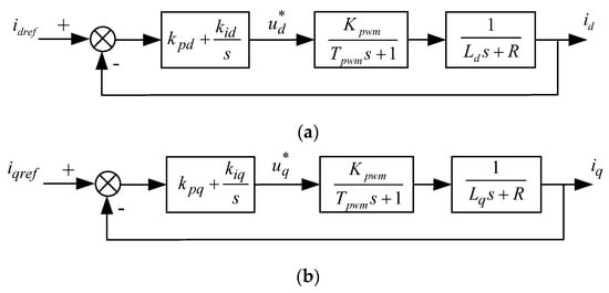
Figure 1.
The PI current-loop structure of IPMSM: (a) d-axis PI current-loop structure; (b) q-axis PI current-loop structure.
In Figure 1, and are the magnification factor and switching cycle of the inverter, respectively. Taking the d-axis PI current-loop structure of IPMSM as an example, the loop transfer function of Figure 1a can be written as
It is assumed that , where is the structure transformation of the PI controller and is the structure transformation of the transfer function of IPMSM; then, the extreme points of the d-axis transfer function of Equation (7) can be eliminated. In this condition, Equation (7) can be regarded as the typical I type system, as shown in Equation (8).
In Equation (8), the parameter is described as . According to the motion control theory of typical I type system [29,30], if the desired overshoot of the d-axis current of IPMSM is less than 5%, then the parameter should be selected as
Under situation of , the proportional coefficient and integral coefficient of the d-axis current loop of IPMSM can be calculated as
In the same way, the proportional coefficient and integral coefficient of the q-axis current loop of IPMSM can be inferred as
In addition, the above PI parameters (, , , and ) of the dq-axis current loop of IPMSM also can be inferred and obtained by the classical automatic control theory. Taking the d-axis PI current-loop structure of IPMSM as an example, based on Equation (8), the d-axis closed-loop transfer function of Figure 1a can be written as
In the classic control theory of some references [31,32], the transfer function of the second-order system can be written as
Therefore, the relationship between the transfer function of the second-order system and typical type I system can be obtained by the comparison of Equations (14) and (15)
After combining Equations (14) and (16), the proportional coefficient and integral coefficient of Equation (14) can be obtained as
If the damping coefficient is (ideal value), then the proportional coefficient and integral coefficient of the d-axis current loop of IPMSM can be further refined as
Similarly, the proportional coefficient and integral coefficient of the q-axis current loop of IPMSM can be inferred as
The comparison of Equations (10)–(13), (19) and (20) indicates that the above two PI parameter tuning results of IPMSM are the same. Actually, the above two PI parameter tuning results of IPMSM all originated from the dynamic performance indicators and empirical formulas of the typical type I system.
3.2. IMC-PI Controller Design
In Section 3.1, the PI parameter tuning result of IPMSM is under the condition of full dq-axis current-loop decoupling. Actually, the existence of salient pole characteristics in IPMSM determines that the dq-axis current loop cannot be fully decoupled. This phenomenon of non-fully decoupled dq-axis current loop is not beneficial to the high-precision and low-sensitivity parameters setting of the controller. In order to ensure the high precision and low sensitivity of the parameters setting of the controller, the IMC method was adopted in this paper to improve traditional PI controller design of the current loop of IPMSM, which is named as the IMC-PI method. Furthermore, it should be noted that the aim of the low-sensitivity parameters setting of the controller is to improve the operational stability (anti-interference ability) of IPMSM. Therefore, there is no contradiction between the high precision and low sensitivity of the parameters setting of the controller.
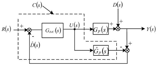
Figure 2.
The structure of IMC.

Table 1.
The parameters of IMC.
According to Equations (21) and (22), the relationship among the system’s output signal , system’s input signal , and interference signal can be expressed as
Based on Equation (23), the structure of IMC (see Figure 2) can be simplified, as shown in Figure 3. In Figure 3, the feedback controller can be described as
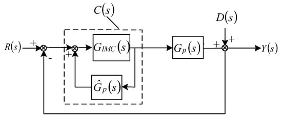
Figure 3.
Equivalent structure simplification of IMC.
If there is no interference signal , and , then the relationship between the system’s input signal and system’s output signal can be expressed as
From Equation (25), it can be concluded that the IMC method is beneficial to ensure the consistence between the system’s input signal and system’s output signal .
Regardless of the interference signal , the d-axis IMC-PI current-loop structure of IPMSM is shown in Figure 4.
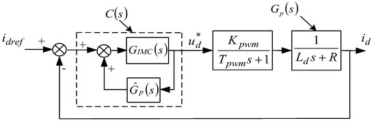
Figure 4.
The d-axis IMC-PI current-loop structure of IPMSM.
It is assumed that , and
where , and is the modulation parameter of the d-axis IMC-PI current-loop structure of IPMSM. On this basis, substitute Equation (26) into Equation (24), then the feedback controller and the parameter tuning results of the d-axis IMC-PI current-loop structure of IPMSM can be obtained as
The comparison results between Equations (19) and (28) indicates that the number of parameter tuning is decreased from two ( and of PI current-loop structure) to one ( of IMC-PI current-loop structure), and thus the difficulty of parameter tuning is also decreased by the IMC-PI current-loop structure of IPMSM.
Similarly, the parameter tuning results of the q-axis IMC-PI current-loop structure of IPMSM can be inferred as
From Equations (28) and (29), it can be concluded that responsiveness of the dq-axis current of IPMSM can be improved by the larger modulation parameter of the IMC-PI current-loop structure. However, the larger modulation parameter will also increase the overshoot and stability time of the dq-axis current. Therefore, the selection of modulation parameter of the IMC-PI current-loop structure should be solved reasonably.
3.3. The Modulation Parameter Selection of IMC-PI
In the practical engineering application, the current loop of IPMSM can be transformed and approximated to one order system. If the inverter transfer function is ignored, then the d-axis open-loop transfer function and d-axis closed-loop transfer function of IPMSM can be described as
Substitute the proportional coefficient and integral coefficient of Equation (28) into Equation (31), then the Equation (31) can be simplified as
where Equation (32) is a closed-loop transfer function with one order system, and its open-loop system is a typical I type system.
According to the definition of bandwidth frequency of typical Type I systems
the modulation parameter of the IMC-PI current-loop structure is also the bandwidth frequency of the closed-loop transfer function of IPMSM. Moreover, the transfer function of the d-axis current loop of IPMSM can be regarded as a system, which is composed of d-axis inductance and resistance . If it is assumed that the parameter , then the modulation parameter of the IMC-PI current-loop structure can be further described as
where the coefficient converts the unit of modulation parameter of the IMC-PI current-loop structure from frequency to radians per second .
Considering that IPMSM has both the d-axis current loop and q-axis current loop, the modulation parameter of the IMC-PI controller is calculated as
4. Simulation Analysis and Experimental Verification
4.1. Simulation Analysis
In order to analyze the difference between the PI method and IMC-PI method, and verify the advantage of the IMC-PI method in improving the dq-axis current reaction time of IPMSM, some simulation analysis is carried out in this section. The electrical parameters of IPMSM are shown in Table 2, and the dq-axis current-loop structure of IPMSM is shown in Figure 5.
Table 2.
Electrical parameters of IPMSM.
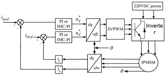
Figure 5.
The dq-axis current-loop structure of IPMSM.
Based on the Equations (19), (20), (28) and (29), and the electrical parameters of IPMSM (see Table 2), the parameter tuning results of the PI method and IMC-PI method are shown in Table 3, and the relevant simulation analysis results of the dq-axis current reaction time of IPMSM are shown in Figure 6, Figure 7 and Figure 8. In the process of simulation analysis, the magnification factor of the inverter is , and the IPMSM’s speed is zero (namely, the IPMSM’s rotor is in the locked condition).
Table 3.
Parameter tuning results of the PI method and IMC-PI method.
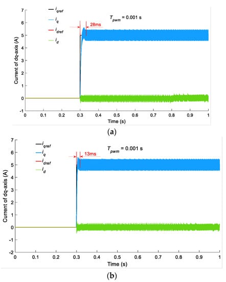
Figure 6.
The simulation analysis results of the dq-axis current reaction time of IPMSM (): (a) PI method; (b) IMC-PI method.
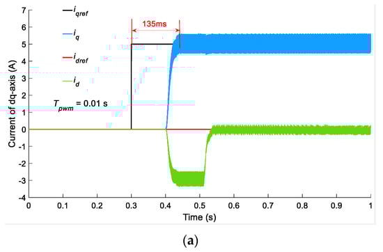
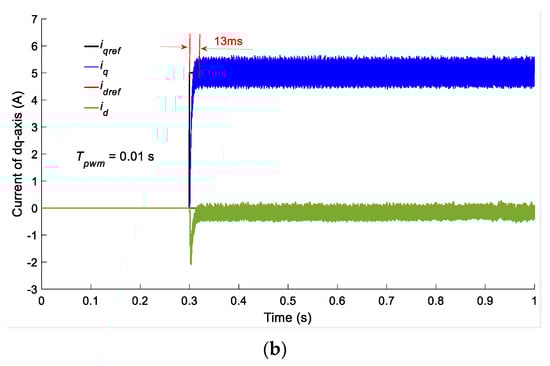
Figure 7.
The simulation analysis results of the dq-axis current reaction time of IPMSM (): (a) PI method; (b) IMC-PI method.
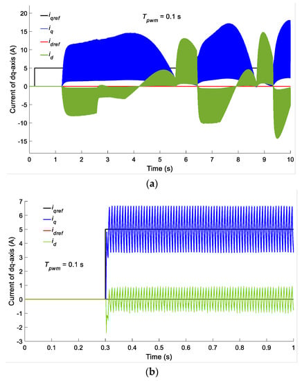
Figure 8.
The simulation analysis results of the dq-axis current reaction time of IPMSM (): (a) PI method; (b) IMC-PI method.
In Figure 6, Figure 7 and Figure 8, the step pulse amplitude of the q-axis target current is , and the d-axis target current is . From Figure 6, Figure 7 and Figure 8, it can be concluded that with the IMC-PI method, the switching cycle of the inverter almost has no impact on the dq-axis current reaction time of IPMSM (, , and , respectively). However, when the switching cycle of the inverter varies from 0.001 s to 0.1 s, the dq-axis current reaction time of IPMSM is decreased by the PI method. For example, based on the PI method and switching cycle , the delay time of the dq-axis current reaction time of IPMSM is approximately 0.1 s, as shown in Figure 7a. What is more important is that when the switching cycle is , the delay time of the dq-axis current reaction time of IPMSM is increased to 1 s (see Figure 8a).
In addition, as the switching cycle increases, the stability of the dq-axis current of IPMSM decreases. For example, the mutual influence between the q-axis feedback current and d-axis feedback current occurs (see Figure 7a and Figure 8a), and even the distortion of the q-axis feedback current and d-axis feedback current occurs (see Figure 8a).
The comparison results among Figure 6, Figure 7 and Figure 8 indicate that by the PI method, the switching cycle of the inverter plays an important role in the dq-axis current reaction time of IPMSM. However, the IMC-PI method can ensure a fine dq-axis current reaction time of IPMSM with a different switching cycle of the inverter. These conclusions are consistent with the above analysis results (the comparison among Equations (19), (20), (28) and (29)).
4.2. Hardware Experimentation
Figure 9 shows the IPMSM’s structure and test platform, where the electrical parameters of IPMSM are the same as Table 2. In Figure 9b, the rotor position of IPMSM is measured by the rotary encoder (2500 lines of resolution ratio), where the rotary encoder is coaxial with the rotor of IPMSM and installated in the back-end department of the rotor. The 2500 lines mean that if the rotor of IPMSM rotates one revolution (360 degrees), the rotary encoder will generate 2500 pulse signals. The more lines of rotary encoder, the more precise the position of the rotor.
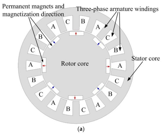
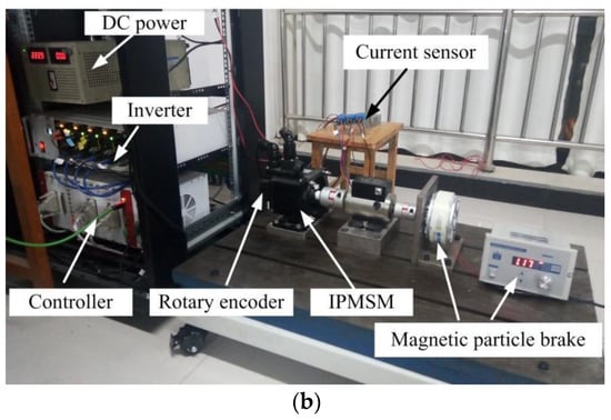
Figure 9.
Experimental test of the dq-axis current reaction time of IPMSM: (a) IPMSM’s structure; (b) test platform.
In order to keep the same operating conditions as the simulation model of Section 4.1, a magnetic particle brake is installed in the test platform of Figure 9b, and the magnetic particle brake is coaxial with the front-end department of the rotor.
During the experimental process, the experimental data were measured by a current sensor and processed by the software of the controller. If the three-phase currents of IPMSM were measured by an oscilloscope, the measured data looks more like the experimental data, but some calculation processes of Park transformation (from three-phase currents to dq-axis currents) should be achieved. Therefore, this paper adopts the current sensor and controller’s software to measure and process the experimental data.
Figure 10 and Figure 11 show the hardware test results of the dq-axis current reaction time of IPMSM by the PI method and IMC-PI method, where the inverter’s switching cycle are 0.001 s and 0.1 s, respectively. With the increase in the inverter’s switching cycle , Figure 10a and Figure 11a indicate that the response time of the q-axis current of IPMSM is 25 ms () and 50 ms (), respectively. However, if the IMC-PI method is adopted, the response time of the q-axis current of IPMSM is nearly stable regardless of whether the inverter’s switching cycle is or , which are shown in Figure 10b and Figure 11b.
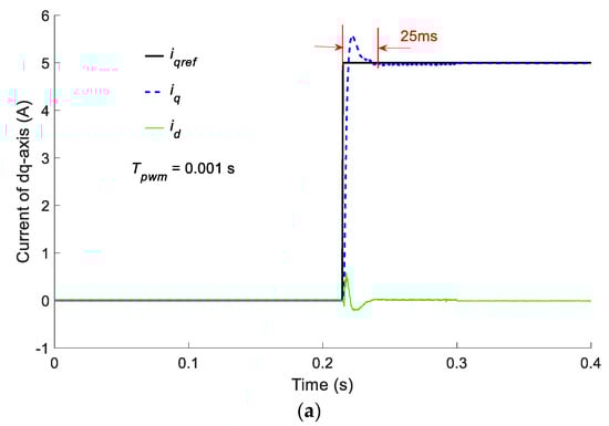
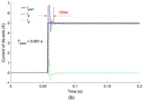
Figure 10.
The hardware test results of the dq-axis current reaction time of IPMSM (): (a) PI method; (b) IMC-PI method.
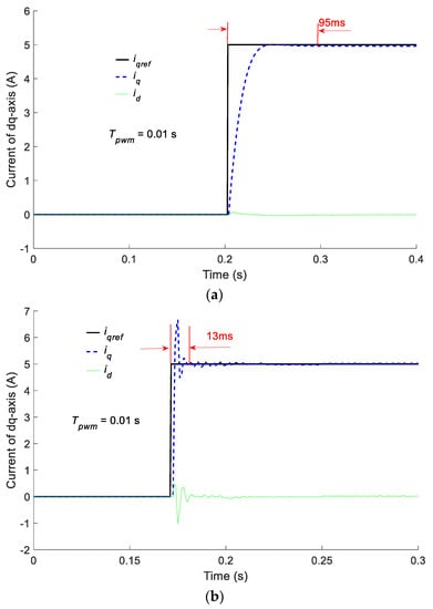
Figure 11.
The hardware test results of the dq-axis current reaction time of IPMSM (): (a) PI method; (b) IMC-PI method.
The comparison between Figure 6 and Figure 10 shows that, in the condition of the inverter’s switching cycle , there is no significant difference in the hardware test result and simulation result. For example, by the PI method, the q-axis current reaction time of the hardware test and simulation are 25 ms and 28 ms, respectively. In another example, the q-axis current reaction time of the hardware test and simulation are 12 ms and 13 ms by adopting the IMC-PI method.
However, with the increasing of the inverter’s switching cycle , a difference in the q-axis current reaction time between the hardware test result and simulation result occurs. Take the inverter’s switching cycle and PI method as an example, the q-axis current reaction time of the hardware test and simulation are 95 ms and 135 ms, respectively. Compared with the PI method, the IMC-PI method still has a good performance, in that the hardware test result (13 ms) agrees with the simulation result (13 ms).
Therefore, the above comparison of the hardware test result and simulation result vividly demonstrates that the dq-axis current reaction time of IPMSM is improved by the IMC-PI method.
Furthermore, because the larger inverter’s switching cycle was not beneficial to the operation of the inverter (such as in the condition of ), the relevant hardware experimental test was not conducted in this paper.
5. Discussion
In Section 4.1 and Section 4.2, the simulation results (see Figure 6 and Figure 7) are compared and verified by hardware experiments (see Figure 10 and Figure 11), and the hardware experiment results indicate that, based on the IMC-PI method, the stability time of the q-axis current start-up response of IPMSM was approximately 12 ms~13 ms, which was better than that of the PI method (25 ms~95 ms). However, the limitations of the proposed IMC-PI method and PI method should be discussed.
Firstly, the dq-axis current start-up response of IPMSM is only an intermediate quantity, and the final dq-axis control effect will be reflected in the speed and torque output of IPMSM.
Secondly, it is not that the shorter the stability time of dq-axis current start-up response of IPMSM the better, because the high overshoot of dq-axis current will cause the severe speed and torque output fluctuation of IPMSM, which is not beneficial to the safe operation and speed change of electric vehicles.
Thirdly, the results of the simulation and hardware experiment also demonstrate that the inverter’s switching frequency has a significant influence on the parameter variation of the PI controller, thus affecting the control performance of the dq-axis current of IPMSM.
Therefore, in the next research work, inverter non-linearities (switching frequency), speed, and torque output of IPMSM should be fully considered, and the parameter variation of the PI method and IMC-PI method should be further researched.
6. Conclusions
Two methods were used in this paper to investigate the dq-axis current reaction time of IPMSM. After the theoretical model and controller design, the current-loop decoupling of IPMSM was presented, and the dq-axis current reaction time of IPMSM was simulated and analyzed. Then, the simulation results were verified by the hardware experiments, and the results of the simulation and hardware experiment indicated that the switching frequency of the inverter had a significant influence on the parameters setting of the PI controller. Lastly, the results of the simulation and hardware experiment demonstrated that, compared with the PI method, the dq-axis current reaction time of IPMSM was improved by the IMC-PI method. In addition, the results of the simulation and hardware experiment also showed that the IMC-PI method had the advantage of the easy setting of the control parameters and was not influenced by the inverter’s switching frequency.
Author Contributions
Conceptualization, A.H. and Z.C.; methodology, A.H. and Z.C.; software, A.H. and J.W.; validation, Z.C.; writing—original draft preparation, Z.C.; writing—review and editing, A.H. All authors have read and agreed to the published version of the manuscript.
Funding
This work was financially supported by the Scientific and Technological Project in Henan Province under Grant No. 232102241024.
Institutional Review Board Statement
Not applicable.
Informed Consent Statement
Not applicable.
Data Availability Statement
Some or all data and models generated or used during the study are available in a repository or online.
Conflicts of Interest
The authors declare no conflict of interest.
References
- Uddin, M.N.; Rahman, M.M.; Patel, B.; Venkatesh, B. Performance of a loss model based nonlinear controller for IPMSM drive incor-porating parameter uncertainties. IEEE Trans. Power Electron. 2019, 34, 5684–5696. [Google Scholar] [CrossRef]
- Shah, S.H.; Wang, X.; Abubakar, U.; Wang, L.; Gao, P. Investigation of noise and vibration characteristics of an IPMSM with modular-type winding arrangements having three-phase sub-modules for fault-tolerant applications. IET Electr. Power Appl. 2022, 16, 248–266. [Google Scholar] [CrossRef]
- Alvaro-Mendoza, E.; Morales JD, L.; Hamida, M.A.; Ghanes, M. Angular position estimation error extraction for speed and angular position estimation of IPMSM using a parameter-free adaptive observer. J. Frankl. Inst. 2022, 359, 7140–7164. [Google Scholar] [CrossRef]
- Zahraoui, Y.; Zaihidee, F.M.; Kermadi, M.; Mekhilef, S.; Mubin, M.; Tang, J.R.; Zaihidee, E.M. Fractional Order Sliding Mode Controller Based on Supervised Machine Learning Techniques for Speed Control of PMSM. Mathematics 2023, 11, 1457. [Google Scholar] [CrossRef]
- Dong, Z.; Liu, C.; Liu, S.; Song, Z. Deadbeat Predictive Current Control for Series-Winding PMSM Drive with Half-Bridge Power Module-Based Inverter. Energies 2021, 14, 4620. [Google Scholar] [CrossRef]
- Shuang, B.; Zhu, Z.Q. A novel method for estimating the high frequency incremental dq-axis and cross-coupling induct-ances in interior permanent magnet synchronous machines. IEEE Trans. Ind. Appl. 2021, 57, 4913–4923. [Google Scholar] [CrossRef]
- Miguel-Espinar, C.; Heredero-Peris, D.; Gross, G.; Llonch-Masachs, M.; Montesinos-Miracle, D. Maximum torque per voltage flux-weakening strategy with speed limiter for PMSM drives. IEEE Trans. Ind. Electron. 2020, 68, 9254–9264. [Google Scholar] [CrossRef]
- Guo, J.; Fan, T.; Li, Q.; Wen, X. Coupling and digital control delays affected stability analysis of permanent magnet synchronous motor current-loop control. In Proceedings of the IEEE Vehicle Power and Propulsion Conference, Hanoi, Vietnam, 14–17 October 2019. [Google Scholar]
- Hernandez, O.S.; Cervantes-Rojas, J.S.; Oliver, J.P.O.; Castillo, C.C. Stator Fixed Deadbeat Predictive Torque and Flux Control of a PMSM Drive with Modulated Duty Cycle. Energies 2021, 14, 2769. [Google Scholar] [CrossRef]
- Xu, L.; Chen, G.; Li, G.; Li, Q. Model Predictive Control Based on Parametric Disturbance Compensation. Math. Probl. Eng. 2020, 2020, 9543928. [Google Scholar] [CrossRef]
- Son, D.-K.; Kwon, S.-H.; Kim, D.-O.; Song, H.-S.; Lee, G.-H. Control Comparison for the Coordinate Transformation of an Asymmetric Dual Three Phase Synchronous Motor in Healthy and Single-Phase Open Fault States. Energies 2021, 14, 1735. [Google Scholar] [CrossRef]
- Yosuke, M.; Shinji, D. High Response Torque Control IPMSM Using State Feedback Control Based N-T Coord. System. Electr. Eng. Jpn. 2019, 206, 51–62. [Google Scholar]
- Zhou, S.; Liu, J.; Zhou, L.; Zhang, Y. DQ current control of voltage source converters with a decoupling method based on preprocessed reference current feed-forward. IEEE Trans. Power Electron. 2017, 32, 8904–8921. [Google Scholar] [CrossRef]
- Ma, Y.; Yang, X.; Zhou, X.; Yang, L.; Zhou, Y. Dual Closed-Loop Linear Active Disturbance Rejection Control of Grid-Side Converter of Permanent Magnet Direct-Drive Wind Turbine. Energies 2020, 13, 1090. [Google Scholar] [CrossRef]
- Qiu, T.; Wen, X.; Zhao, F.; Wang, Y. Permanent magnet flux linkage adaptive observer for permanent magnet synchronous motor. In Proceedings of the IEEE Transportation Electrification Asia-Pacific, Beijing, China, 31 August–3 September 2014. [Google Scholar]
- Qiu, T.; We, X.; Zhao, F. Design strategy of permanent magnet flux linkage adaptive observer for permanent magnet synchronous motor. Proc. Chin. Soc. Electr. Eng. 2015, 35, 2287–2294. [Google Scholar]
- Saleh, M.; Hamid, Y.; Mojtaba, A.K. Adaptive sliding-mode type-2 neuro-fuzzy control of an induction motor. Expert Syst. Appl. 2015, 42, 6635–6647. [Google Scholar]
- Moradi, H.; Yaghobi, H.; Alinejad-Beromi, Y.; Bustan, D. Power-control and speed-control modes of a DFIG using adaptive sliding mode type-2 neuro-fuzzy for wind energy conversion system. IET Renew. Power Gener. 2020, 14, 2946–2954. [Google Scholar] [CrossRef]
- Xu, W.; Junejo, A.K.; Liu, Y.; Hussien, M.G.; Zhu, J. An Efficient Antidisturbance Sliding-Mode Speed Control Method for PMSM Drive Systems. IEEE Trans. Power Electron. 2020, 36, 6879–6891. [Google Scholar] [CrossRef]
- Ahmed, W.A.E.M.; Adel, M.M.; Taha, M.; Saleh, A.A. PSO technique applied to sensorless field-oriented control PMSM drive with discretized RL-fractional integral. Alex. Eng. J. 2021, 60, 4029–4040. [Google Scholar] [CrossRef]
- Eshwar, K.; Kumar, T.V. Reduction of torque and flux ripples in direct torque control for three-level open-end winding PMSM drive. IET Electr. Power Appl. 2020, 14, 2843–2854. [Google Scholar] [CrossRef]
- Heidari, R. Model predictive combined vector and direct torque control of SM-PMSM with MTPA and constant stator flux magnitude analysis in the stator flux reference frame. IET Electr. Power Appl. 2020, 14, 2283–2292. [Google Scholar] [CrossRef]
- Sreejith, R.; Singh, B. Sensorless Predictive Current Control of PMSM EV Drive Using DSOGI-FLL Based Sliding Mode Observer. IEEE Trans. Ind. Electron. 2020, 68, 5537–5547. [Google Scholar] [CrossRef]
- Bensalem, Y.; Kouzou, A.; Abbassi, R.; Jerbi, H.; Kennel, R.; Abdelrahem, M. Sliding-Mode-Based Current and Speed Sensors Fault Diagnosis for Five-Phase PMSM. Energies 2021, 15, 71. [Google Scholar] [CrossRef]
- Zhu, S.; Huang, W.; Lin, X.; Jiang, W.; Dong, D.; Wu, X. Simplified model predictive torque control for permanent magnet synchronous motor in static coordinate system. In Proceedings of the IEEE International Symposium on Predictive Control of Electrical Drives and Power Electronics, Quanzhou, China, 31 May–2 June 2019. [Google Scholar]
- Lemmens, J.; Vanassche, P.; Driesen, J. PMSM Drive Current and Voltage Limiting as a Constraint Optimal Control Problem. IEEE J. Emerg. Sel. Top. Power Electron. 2014, 3, 326–338. [Google Scholar] [CrossRef]
- Yuan, L.; Hu, B.X.; Wei, K.Y.; Chen, S. The Control Principle and MATLAB Simulation of Modern Permanent Magnet Synchronous Motor; Beijing University of Aeronautics and Astronautics Press: Beijing, China, 2016. [Google Scholar]
- Ricardo, H. A Modern Introduction to Differential Equations; Elsevier Press: Amsterdam, The Netherlands, 2015. [Google Scholar]
- Chen, B. Electric Drive Automatic Control System: Motion Control System, 3rd ed.; China Machine Press: Beijing, China, 2007. [Google Scholar]
- Gu, C.; Chen, Z. Electric Drive Automatic System and MATLAB Simulation; Tsinghua University Press: Beijing, China, 2011. [Google Scholar]
- Gene, F.F. Principles and Design of Automatic Control, 8th ed.; Publishing House of Electronics Industry: Beijing, China, 2021. [Google Scholar]
- Hu, S. Automatic Control Principle, 6th ed.; Science Press: Beijing, China, 2015. [Google Scholar]
Disclaimer/Publisher’s Note: The statements, opinions and data contained in all publications are solely those of the individual author(s) and contributor(s) and not of MDPI and/or the editor(s). MDPI and/or the editor(s) disclaim responsibility for any injury to people or property resulting from any ideas, methods, instructions or products referred to in the content. |
© 2023 by the authors. Licensee MDPI, Basel, Switzerland. This article is an open access article distributed under the terms and conditions of the Creative Commons Attribution (CC BY) license (https://creativecommons.org/licenses/by/4.0/).