Article

A Dynamic Cache Allocation Mechanism (DCAM) for Reliable Multicast in Information-Centric Networking

1
National Network New Media Engineering Research Center, Institute of Acoustics, Chinese Academy of Sciences, No. 21, North Fourth Ring Road, Beijing 100190, China
2
School of Electronic, Electrical and Communication Engineering, University of Chinese Academy of Sciences, No. 19(A), Yuquan Road, Beijing 100049, China
*
Author to whom correspondence should be addressed.
Future Internet 2022, 14(4), 105; https://doi.org/10.3390/fi14040105
Submission received: 2 March 2022 / Revised: 12 March 2022 / Accepted: 23 March 2022 / Published: 25 March 2022
(This article belongs to the Special Issue 5G Wireless Communication Networks)

Abstract

:
As a new network architecture, information-centric networking (ICN) decouples the identifiers and locators of network entities and makes full use of in-network cache technology to improve the content distribution efficiency. For reliable multicast, ICN in-network cache can help reduce the loss recovery delay. However, with the development of applications and services, a multicast tree node often serves multiple reliable multicast groups. How to reasonably allocate cache resources for each multicast group will greatly affect the performance of reliable multicast. In order to improve the overall loss recovery performance of reliable multicast, this paper designs a dynamic cache allocation mechanism (DCAM). DCAM considers the packet loss probability, the node depth of the multicast tree, and the multicast transmission rate of multicast group, and then allocates cache space for multicast group based on the normalized cache quota weight. We also explore the performance of three cache allocation mechanisms (DCAM, AARM, and Equal) combined with four cache strategies (LCE, CAPC, Prob, and ProbCache), respectively. Experimental results show that DCAM can adjust cache allocation results in time according to network changes, and its combinations with various cache strategies outperform other combinations. Moreover, the combination of DCAM and CAPC can achieve optimal performance in loss recovery delay, cache hit ratio, transmission completion time, and overhead.

1. Introduction

With the update of applications and the surge in network traffic, data has become the core requirement of network communication. The current TCP/IP network architecture is host-centric, and has a connection-oriented mode [1]. It has inherent defects in data distribution efficiency, mobility, scalability, security, and quality of service (QoS). Researchers are beginning to investigate new network architectures.
As a new network architecture, the information-centric network (ICN) [2,3,4] has received extensive attention. The core idea of the ICN is to separate identification and address [5], and to provide efficient content distribution through technologies such as content-oriented name [6], in-network cache [7], and multicast [8]. On the one hand, ICN effectively supports typical application scenarios such as efficient content distribution, multicast transmission, and mobile handover management. On the other hand, 5G (fifth generation) and future networks have a trend of changing from “best effort” to “deterministic data transmission”. Therefore, researchers consider the integration of ICN technology and 5G network architecture to provide reliable deterministic latency guarantees for typical applications scenarios such as industrial control and Internet of Vehicles, and realize the 5G vision. Some ICN solutions have been proposed, such as NDN [9], SEANet [10], and MobilityFirst [11]. However, it still has some problems [12], such as the reliability of multicast transmission. In ICN, multicast application scenarios with reliability requirements are ubiquitous, such as file transfer, software upgrade, and distribution of key data in the Internet of Things. Although multicast improves network bandwidth utilization by simultaneously sending information from one or more points to a group of other points [13], it does not guarantee reliable and orderly delivery of all data to each multicast receiver [14].
Loss recovery is the core issue of reliable multicast, and the recovery delay seriously affects the performance of reliable multicast applications [15]. The in-network cache capability of the ICN enables multicast tree nodes to cache multicast data and retransmit the requested data immediately after receiving the retransmission request, which greatly reduces the recovery delay. Researchers have proposed several cache strategies for a single multicast group to improve the loss recovery performance. However, a multicast tree node (MTN) often serves multiple multicast groups at the same time, and the multicast traffic flowing through the same multicast tree node may reach different downstream links respectively. The packet loss situation of each multicast group may be different, and the demand for cache resources of multicast tree nodes is different [16].
In the above network scenario, the allocation of cache space of multicast tree nodes has a great impact on the performance of reliable multicast. If the cache space of each multicast tree node in the network is arbitrarily allocated, it is unfair and unreasonable. For example, the multicast group with a small retransmission requirement may cause a waste of cache space; for a multicast group with a large retransmission requirement, the cache quota of the multicast tree node may be insufficient [17], resulting in a large delay in loss recovery. Therefore, it is very important to reasonably allocate the cache space of multicast tree nodes to each multicast group.
In order to optimize the overall loss recovery performance of all multicast groups and improve the utilization of cache resources in the network, this paper comprehensively considers the packet loss probability, node depth, and transmission rate to design a dynamic cache allocation mechanism (DCAM). We also combine the three cache allocation mechanisms (DCAM, AARM [18], Equal [19]) with the four cache strategies (LCE [9], CAPC [20], ProbCache [21], Prob [22]), and conduct experiments to compare their performance. Experiments show that, among all combinations of cache allocation mechanisms and cache strategies, the combination of DCAM and CAPC performs best in terms of loss recovery delay, cache hit ratio, transmission completion time, and overhead.
The remainder of this paper is organized as follows. We review the related work about cache allocation mechanisms in Section 2. Section 3 describes the problem based on the constructed model. Section 4 introduces the proposed dynamic cache allocation mechanism in detail, including the weight definitions corresponding to the three parameters and cache quota calculation method. Then we describe the experiment environment settings, evaluate the performance, and discuss the simulation experiment results in Section 5. Finally, we conclude the work in Section 6.

2. Related Work

In the field of reliable multicast, the design of many router cache management strategies is limited by the network environment with a single multicast group. In a network environment where router cache resources are shared by multiple multicast groups, using such a strategy cannot improve the overall loss recovery performance. Therefore, some related literatures have studied some cache allocation mechanisms in reliable multicast, and the representative works are as follows:
Reference [23] proposed a cache management method called adaptive cache pool (ACP). In ACP, the router calculates the ratio of the number of NACKs received for a multicast group to the total number of NACKs received, and allocates cache space for each multicast group accordingly. It also proposes a “borrow” and “return” policy to allow a multicast group to “borrow” unused cache space in ACP when it runs out of allocated space. When all cache space in active router is used up, ACP will activate the “return” policy. Additionally, it prioritizes the group with the smallest number of NACKs to execute the “return” policy first. However, burst traffic often occurs on the Internet. When the number of multicast groups or group members change, the ACP allocation method has disadvantages such as slow convergence speed and unstable allocation results.
Reference [18] proposed an adaptive and active reliable multicast (AARM) protocol suitable for large-scale multicast networks, in which the cache allocation algorithm is divided into two steps. Step 1 is to estimate the average packet loss rate of the multicast group according to the exponentially weighted moving average of NACK, and pre-allocate cache space according to the ratio of the number of NACK of the multicast group to the total number of NACK. In order to avoid the unfair phenomenon caused by the group with high packet loss rate occupying too much cache space, step 2 performs secondary correction on the group whose cache quota does not meet the retransmission requirement. Although AARM improves bandwidth consumption and network throughput, and decreases recovery delay compared with ACP, AARM does not consider the influence of the relative position of routers on the multicast tree.
In [19], for the cache management problem of reliable multicast, the authors have studied three cache strategies based on timer, simple FIFO (S-FIFO) and probabilistic FIFO (P-FIFO), and three cache allocation mechanisms—namely equal sharing, least requirement first (LRF), and proportional allocation. Then, the authors compared the performance of various combinations of cache strategies and cache allocation mechanisms. In most cases, the combination of proportional allocation and P-FIFO performs the best.
The router cache resource configuration has a great impact on network performance, therefore it has always been a research direction of attention. Different cache allocation mechanisms can be obtained based on different network environments. Under the current complex time-varying network characteristics, the router cache allocation mechanisms need to consider different factors, and dynamically adjust the cache configuration according to network state changes [24]. The following cache allocation mechanisms are considered from different aspects, reflecting some factors that affect the cache demand.
In CCN, a dynamic cache size transfer scheme (DCSTS) [25] based on replacement rate has been proposed. In view of the differences in the usage of cache space, DCSTS allows dynamic loaning of cache resources between nodes. Nodes with large cache demand can use relatively idle resources of other nodes, so the cache performance of overloaded nodes can be improved. However, it also introduces additional overhead.
Additional buffer block allocation (ABBA) on demand is a dynamic allocation mechanism for the buffer space of packet switches or routers. By introducing basic buffer space (working block) and additional space (additional block), the cache space of each (or a certain type of) service flow obtains a dynamic adjustment range to adapt to changes in cache requirements [26]. In order to obtain the best overall packet loss rate performance when the remaining cache space in the system is small, several important factors affecting the dynamic allocation of additional blocks and the corresponding allocation decision functions and allocation algorithms are also discussed in [26].
In order to reasonably configure the cache space for ICN routers, [17] proposed a cache allocation mechanism based on node weights, in which the definition of node weights comprehensively considers degree weights, router compactness, network centrality, and request influence. Compared with the allocation mechanisms based on uniform allocation and uniform request influence, the cache space utilization and cache hit ratio are improved.

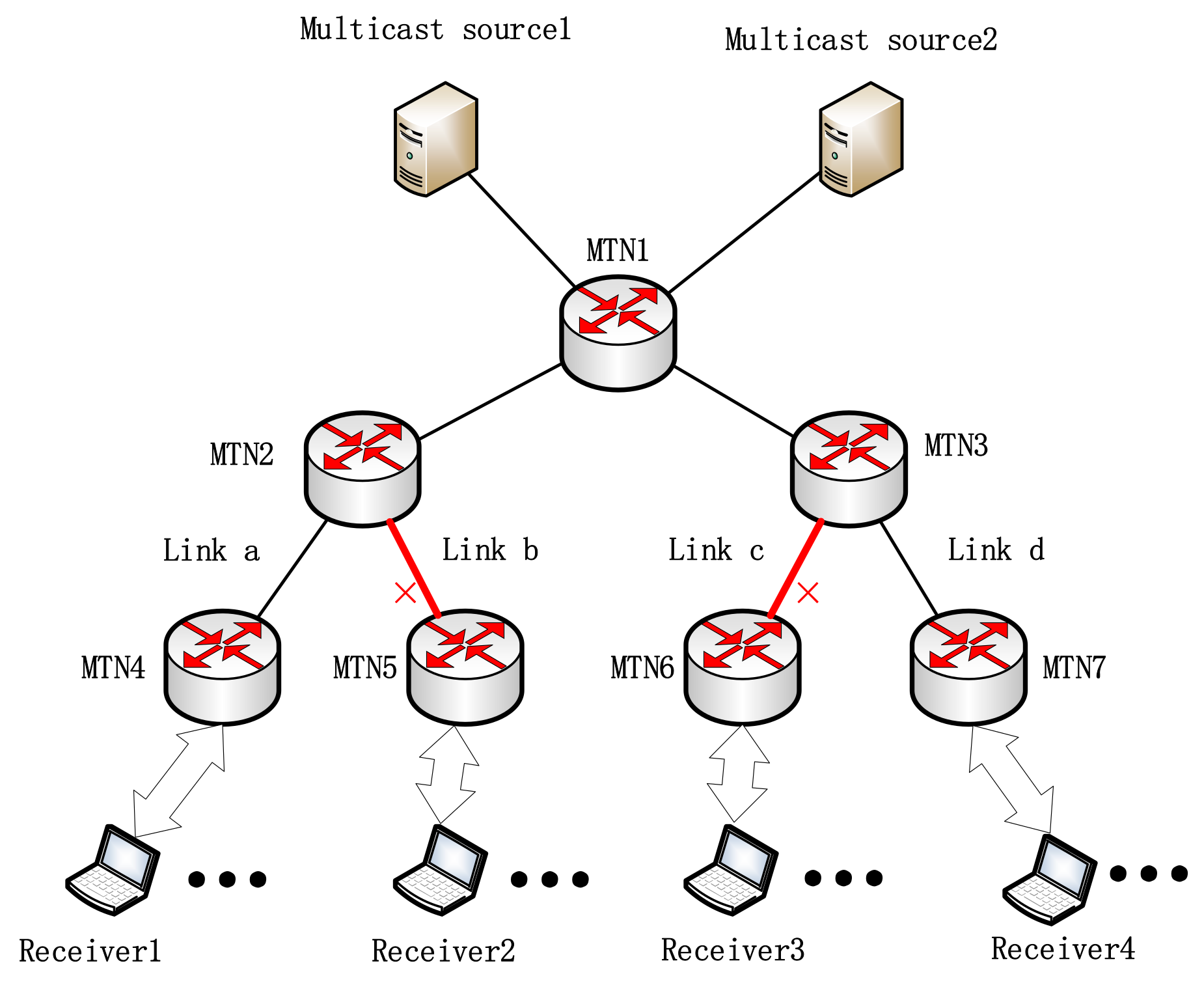
3. Problem Description

The in-network cache capability of the ICN network provides the possibility for the nearest retransmission of reliable multicast. Routers can respond to retransmission requests from multicast receivers by caching recently transmitted chunks to reduce loss recovery delay. However, if there are multiple multicast groups in the network, how to allocate cache space for them affects the loss recovery performance.
In ICN, each multicast group is regard as an entity and is assigned with a globally unique multicast service identifier (GUMSID). As shown in Figure 1, based on the reliable multicast architecture proposed in [20], we illustrate the shortcomings of the existing cache allocation mechanisms through a three-layer multicast tree model. There are two reliable multicast groups in Figure 1, namely GUMSID1 and GUMSID2. An MTN is a router with in-network cache capability. Multicast source1 and multicast source2 are senders of GUMSID1 and GUMSID2 respectively. Receiver1 and receiver3 join GUMSID1, and receiver2 and receiver4 join GUMSID2. Links a and d are reliable links, and links b and c are unreliable links.
Assuming that the packets are not lost in the transmission process of the reliable link, MTN2 will not receive a NACK packet from receiver1 of GUMSID1, but may receive a NACK packet from receiver2 of GUMSID2. Similarly, MTN3 will not receive a NACK packet from receiver4 of GUMSID2, but may receive a NACK packet from receiver3 of GUMSID1. If the cache capacity of MTN2 and MTN3 is infinite, they can cache all the data packets passed by the flow. When receiving a NACK, MTN can always find the corresponding data packets in its cache and forward them as recovery packets. However, in a real network environment, the cache resources of router are limited. Assuming that the cache resources of MTN2 or MTN3 are exhausted, but the data packets of the multicast groups GUMSID1 and GUMSID2 continue to arrive, the data packets arriving later cannot be cached.
If simple FIFO is used as the cache allocation mechanism, when the transmission rates of the multicast groups GUMSID1 and GUMSID2 are the same, the cache space of the router is equally allocated to the two multicast groups. However, when the rate of the multicast group GUMSID1 is much larger than GUMSID2, more cache space is allocated to GUMSID1. When GUMSID2 encounters packet loss, the corresponding data packets can hardly be found in the cache space of the router, and the nearest retransmission cannot be provided for the group. Thus, NACK can only be forwarded to the upstream, which greatly increases the loss recovery delay. In a word, in the scenario where multiple multicast groups exist and their transmission rates are different, the loss recovery performance of simple FIFO is relatively poor.
For the defect of simple FIFO, a possible improvement mechanism is equal allocation; that is, the cache space of the router is evenly allocated to the multicast groups GUMSID1 and GUMSID2. However, MTN2 will never receive a NACK from GUMSID1, and MTN3 will never receive a NACK from GUMSID2. Fifty percent of the cache space of MTN2 and MTN3 is wasted, so this allocation mechanism cannot efficiently utilize cache resources.
From the above discussion of the two traditional methods, it can be seen that when there are multiple multicast groups in the network and the cache resources of multicast tree nodes are shared by those multicast groups, the recovery delay of reliable multicast is related to multiple characteristics of each multicast group. The cache allocation mechanism that only considers a single factor is unreasonable.

4. Design of Dynamic Cache Allocation Mechanism

Aiming at the problem that cache resources in ICN are shared by multiple reliable multicast groups and the existing cache allocation mechanism is not reasonable enough, this section proposes a dynamic cache allocation mechanism (DCAM). DCAM selects three factors including the number of NACKs of multicast groups, the distance from the MTN to the multicast source, and the arrival rate of the multicast group in the network, which respectively reflect the packet loss probability, node depth, and transmission rate of the multicast group. By comprehensively considering these three factors, DCAM evaluates the cache requirements of the multicast group and adjusts the cache quota of the multicast group in time to optimize the overall loss recovery delay and cache resource utilization. This section first defines the above three factors as NACK weight, distance weight, and rate weight, and then gives the calculation method of the normalized cache quota weight and the cache quota. The overall pseudo code of DCAM is shown in Algorithm 1.
Algorithm 1. The Dynamic Cache Allocation Mechanism
Input: C , α , β , γ , θ
Output: C i , n
1: 
    Initialization: α = 0.3 ,   β = 0.3 ,   γ = 0.4 , θ = 0.9
2: 
    In the construction of the multicast tree, each MTN records the number of hops H i , n from itself to each multicast source and calculates the total number of hops by j M   H j , n  
3: 
    Each MTN records the number of NACK N A C K i , n of the multicast group i in the n -th statistical period, and calculates weighted moving average of NACK E W M A _ N A C K i , n using Equation (1), then calculates the total number of NACK by j = 1 M E W M A _ N A C K j , n
4: 
    Each MTN records the number of multicast data packets S i , n of multicast group i in the n-th statistical period, then calculates the total multicast data packets by j M   S j , n  
5: 
    for multicast group i in G U M S I D 1 G U M S I D M do
6: 
              Calculate NACK weight N i , n , distance weight D i , n , and rate weight R i , n using Equations (2)–(4), respectively
7: 
              Calculate cache weight W i , n using Equation (5)
8: 
              Calculate the final cache quota weight Q W i , n using Equation (6)
9: 
              Update the cache quota C i , n of multicast group i in the n -th statistical period using Equation (7)
10: 
   return C i , n

4.1. Weight Definition

Assuming that there are M multicast groups in the current network, the number of NACKs of the multicast group, the distance from the MTN to the multicast source, and the arrival rate of the multicast group are defined as the NACK weight, the distance weight, and the rate weight, respectively. The specific definitions are as follows.

4.1.1. Definition 1: NACK Weight

In reliable multicast, the role of cache is to retransmit lost data as close as possible. The NACKs received by the multicast tree node are more likely to belong to the multicast group with more lossy downstream links in the multicast tree, thus the number of NACKs of the multicast group reflects the packet loss probability of the multicast group. To avoid unreasonable cache reallocation caused by transient changes in the number of NACKs, we adopt a weighted moving average of the number of NACK. As shown in Equation (1), let N A C K i , n be the number of NACK of multicast group i in the n -th statistical period, and the weighted moving average of NACK E W M A _ N A C K i , n is calculated according to [27].
  E W M A _ N A C K i , n = 1 θ × E W M A _ N A C K i , n 1 + θ × N A C K i , n
where, θ ( 0 < θ < 1 ) is a weighting factor.
Then, we calculate the ratio of the number of NACK of each multicast group to the total number of NACK received by the MTN. The higher the NACK ratio of a multicast group is, the higher the packet loss probability of the multicast group is, and the greater the possibility that the multicast group needs to perform retransmission is. At the same MTN, N i , n represents the NACK weight of multicast group i in the n -th statistical period.
N i , n = E W M A _ N A C K i , n / j = 1 M E W M A _ N A C K j , n

4.1.2. Definition 2: Distance Weight

The distance from the MTN to the multicast source is essentially the node depth. If the NACK is not hit in the cache of an MTN, it will be forwarded to the upstream until the multicast source. The farther the current node is from the multicast source, the larger the loss recovery delay is. To reduce the loss recovery delay, the larger the distance between an MTN and a multicast source is, the more cache space should be allocated to the multicast group; otherwise, the smaller cache space should be allocated to it. Let H i , n be the number of hops from the MTN to multicast source i . According to Equation (3), at the same MTN, the distance weight D i , n of the multicast group i in the n -th statistical period can be obtained by
  D i , n =   H i , n   / j M   H j , n  

4.1.3. Definition 3: Rate Weight

The higher the transmission rate of a multicast group is, the more multicast packets arrive per unit time. Therefore, more cache space should be allocated for the multicast group to perform a retransmission response when the NACK is received. The MTN periodically collects statistics on the number of the received multicast data packets. Let S i , n denote the number of multicast data packets of multicast group i received by MTN in the n -th statistical period. According to Equation (4), at the same MTN, the rate weight R i , n of multicast group i in the n -th statistical period can be obtained by
R i , n = S i , n / j M S j , n

4.2. Normalized Weight and Cache Allocation

According to Equation (5), the NACK weight, distance weight, and rate weight are respectively multiplied by the corresponding weight coefficients α , β , and γ , and then they are added together. Then the cache weight W i , n of the multicast group i in the n -th statistical period can be calculated.
W i , n = α × N i , n + β × D i , n + γ × R i , n
where 0   α , β , γ 1 , and α + β + γ = 1 . The size of the weight coefficients reflects the relative importance of the corresponding weight parameters in the reliable multicast cache allocation. Since different multicast applications have different emphasis on network performance indicators, the cache weight corresponding to each multicast group can be calculated by adjusting the weight coefficient corresponding to each weight parameter.
In order to allocate all the available cache space to the multicast group, we normalize the cache weight of each multicast group, and the final weight Q W i , n of the cache quota for multicast group i is
Q W i , n = W i , n / j M W j , n
where, Q W i , n of each multicast group satisfies i M Q W i , n = 1 . Q W i , n reflects the proportion of the cache space that the multicast group can obtain in a multicast tree node.
Let the total available cache resources be C (in units of chunk). According to Equation (7), the cache size allocated to multicast group i in the n -th statistical period (represented by C i , n ) is
C i , n =   Q W i , n × C
where, . represents the floor operator.

5. Evaluation

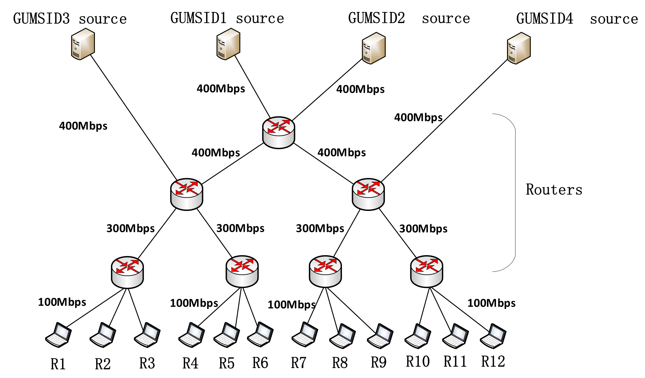
5.1. Simulation Setup

The simulation experiment platform uses NS-2 [28]. In this paper, we verify the proposed mechanism by introducing a three-layer multicast tree structure, and the mechanism is applicable to multicast tree topology of any number of layers. The experimental topology and link bandwidth settings are shown in Figure 2. The propagation delay of the links is set to 10ms. There are four reliable multicast groups in the network, namely GUMSID1, GUMSID2, GUMSID3, and GUMSID4. The multicast source of GUMSID1 and the multicast source of GUMSID2 are far away from the multicast receiver, and the multicast source of GUMSID3 and the multicast source of GUMSID4 are relatively close to the multicast receiver. Receiver1, receiver4, receiver7, and receiver10 join GUMSID1; receiver2, receiver5, receiver8, and receiver11 join GUMSID2; receiver3 and receiver6 join GUMSID3; and receiver9 and receiver12 join GUMSID4. The rates of the multicast sources of the four multicast groups are initialized to 100 Mbps. When the experiment runs to 0.9s, the rates of the multicast source of GUMSID3 and the multicast source of GUMSID4 become 70 Mbps. To accurately evaluate the performance of the proposed mechanism, all packet losses in the experiments are caused by network congestion.
Table 1 shows the parameter settings of our simulation experiments. We compared DCAM with AARM [18] and Equal [19] with regard to loss recovery delay, cache hit ratio, transmission completion time, and overhead under different cache strategies (LCE [9], CAPC [20], ProbCache [21], and Prob [22]). The parameter settings of CAPC, ProbCache, and Prob refer to [20].
One of the most important performance indicators of reliable multicast is the loss recovery delay. In order to evaluate the impact of the setting of the weight coefficients α , β , and γ on the loss recovery delay, we conducted a large number of experiments under different combinations of weight coefficients. In this experiment, DCAM is used with CAPC cache strategy. As shown in the Figure 3, when the values of α , β , and γ are set to 0.3, 0.3, and 0.4, respectively, the DCAM-CAPC combination achieves the smallest normalized loss recovery delay, so all experiments in this paper adopt this setting.

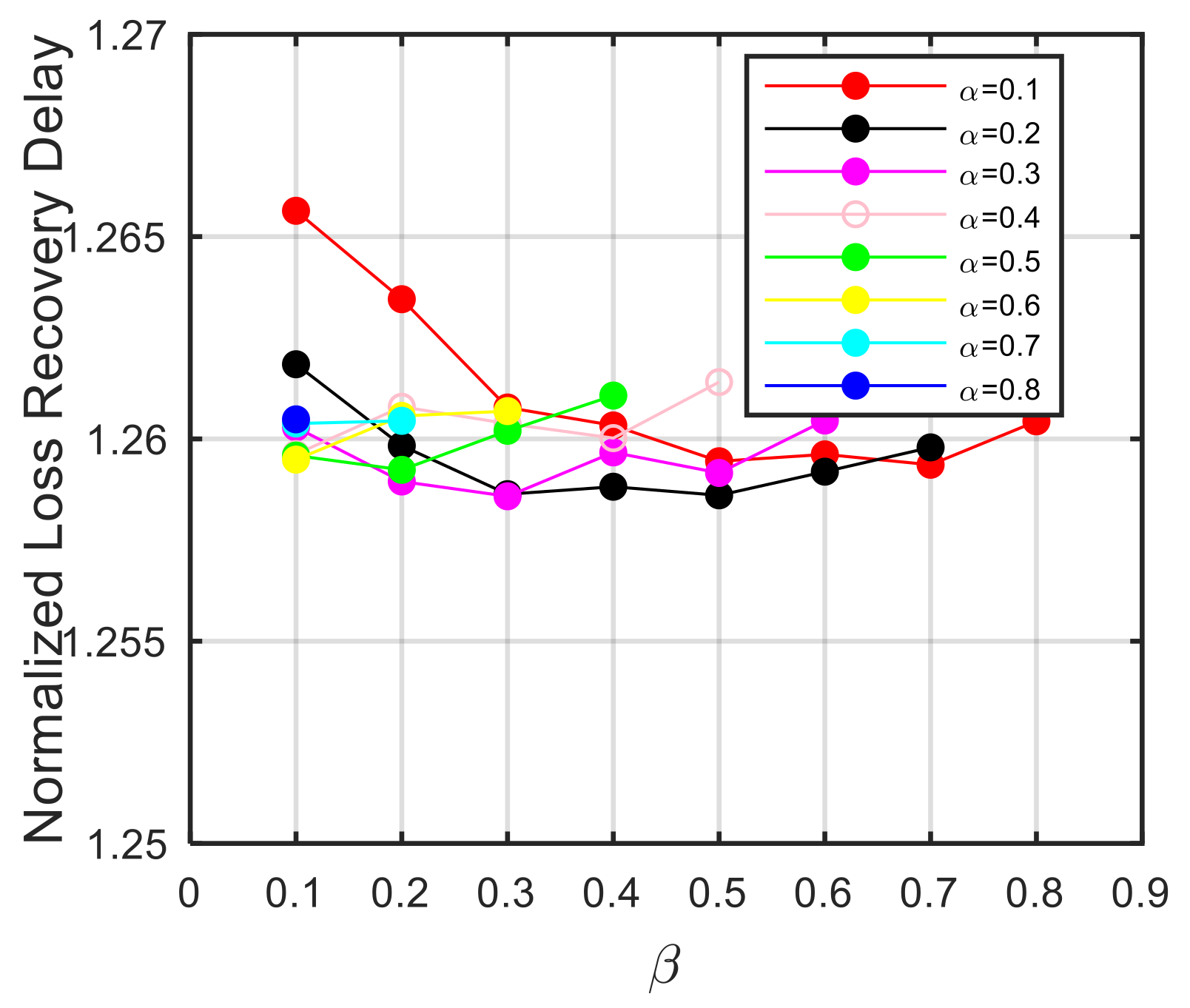
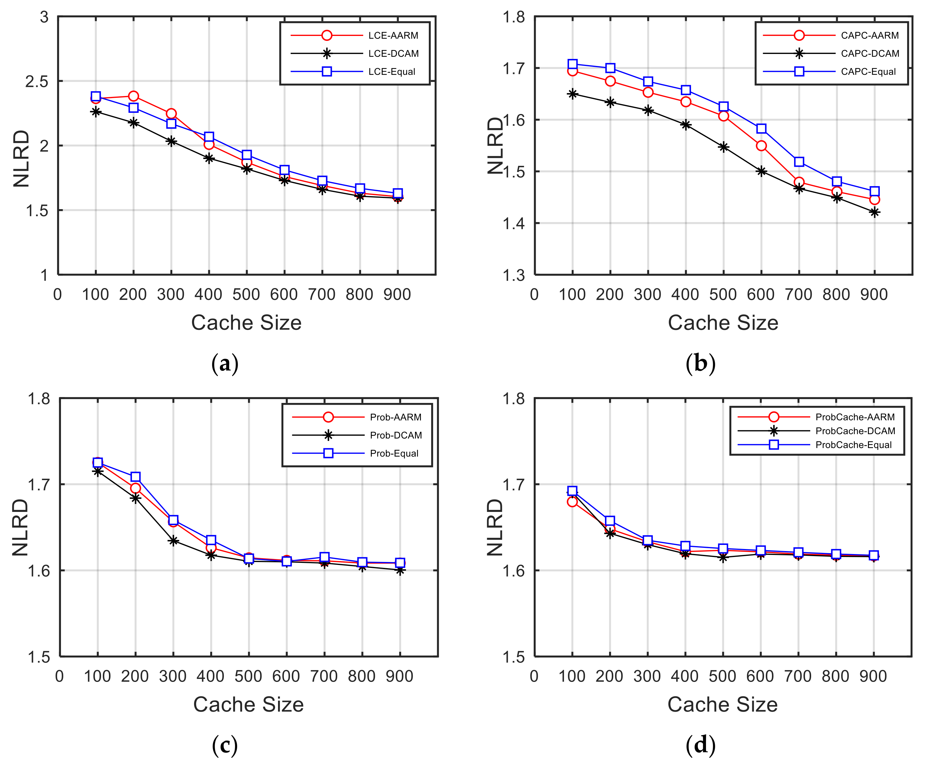
5.2. Loss Recovery Delay

Loss recovery delay is defined as the time interval between the receiver first detecting the packet loss and the receiver receiving the recovery packet. Suppose there are R receivers. Let D ¯ r be the average loss recovery delay of multicast receiver r , and R T T ¯ be the mean round trip time from all multicast sources to all receivers. Then we evaluate the loss recovery delay by the normalized loss recovery delay (NLRD) D ¯ , which is defined in Equation (8).
  D ¯ = 1 R r = 1 R D ¯ r R T T ¯
Figure 4 compares the NLRD achieved by the combinations of four cache strategies and three cache allocation mechanisms under different cache sizes. It can be seen that, as the cache size increases, the NLRD of all combinations becomes smaller. This is because the larger cache space allows more chunks to be cached.
On the one hand, the NLRD achieved by the combinations of DCAM and different cache strategies are smaller than that of other combinations, for example, when the cache size is 600, the NLRD of DCAM-CAPC is 3.18% and 5.21% lower than that of AARM-CAPC and Equal-CAPC, respectively. When the cache size is 300, the NLRD of DCAM-LCE is 9.52% and 6.27% lower than that of AARM-LCE and Equal-LCE, respectively. This is because DCAM comprehensively considers factors such as packet loss probability, node depth, transmission rate to calculate the cache allocation result. DCAM can quickly respond and adjust cache quota for each multicast group with network changes. AARM first estimates the cache quota of a multicast group based on the ratio of weighted moving average of NACK of the multicast group to total number of NACK, and then adjusts for the group whose quota is lower than the number of packets arriving per unit time. In fact, only two factors, such as packet loss rate and transmission rate, are considered in AARM, therefore the NLRD achieved by various cache strategies based on the AARM allocation results is greater than that achieved by various cache strategies based on the DCAM allocation results. The NLRD achieved by the combinations of Equal and the four cache strategies are the largest. This is because Equal simply distributes the MTN’s cache space evenly to all multicast groups, resulting in low cache resource utilization.
On the other hand, as seen from Figure 4a,b, the NLRD achieved by the combinations of CAPC and all allocation mechanisms is the smallest, while the NLRD achieved by the combinations of LCE and all allocation mechanisms is the largest when the cache space is small. This is because CAPC takes into account the congestion condition and the location of cache nodes on the multicast tree, so that CAPC can provide better loss recovery services. The advantages of CAPC have been demonstrated in [20]. However, LCE caches all chunks along the way. Due to limited cache space, cache replacement occurs frequently. The requested chunks are likely to have been replaced before the corresponding retransmission requests arrive. As the cache space becomes larger, LCE can cache more chunks, so NLRD is relatively small. ProbCache and Prob randomly cache the passing chunks. Some chunks that do not experience loss will occupy the cache space, so that only a small number of lost packets are recovered through multicast tree nodes. Therefore, the NLRD achieved by ProbCache and Prob in combination with various cache allocation mechanisms is relatively large. When the cache size is 900, based on the cache allocation results of DCAM, the NLRD of CAPC is reduced by 10.78%, 11.21%, and 12.06% compared with LCE, Prob, and ProbCache, respectively.
In conclusion, among all combinations, DCAM combined with CAPC can achieve the smallest NLRD, and the DCAM-CAPC can reduce NLRD by up to 31.44%, 27.07%, 30.71%, 3.2%, 5.2%, 11.65%, 11.21%, 11.67%, 12.11%, 12.06%, and 12.14% compared with AARM-LCE, DCAM-LCE, Equal-LCE, AARM-CAPC, Equal-CAPC, AARM-Prob, DCAM-Prob, Equal-Prob, AARM-ProbCache, DCAM-ProbCache, and Equal-ProbCache, respectively.

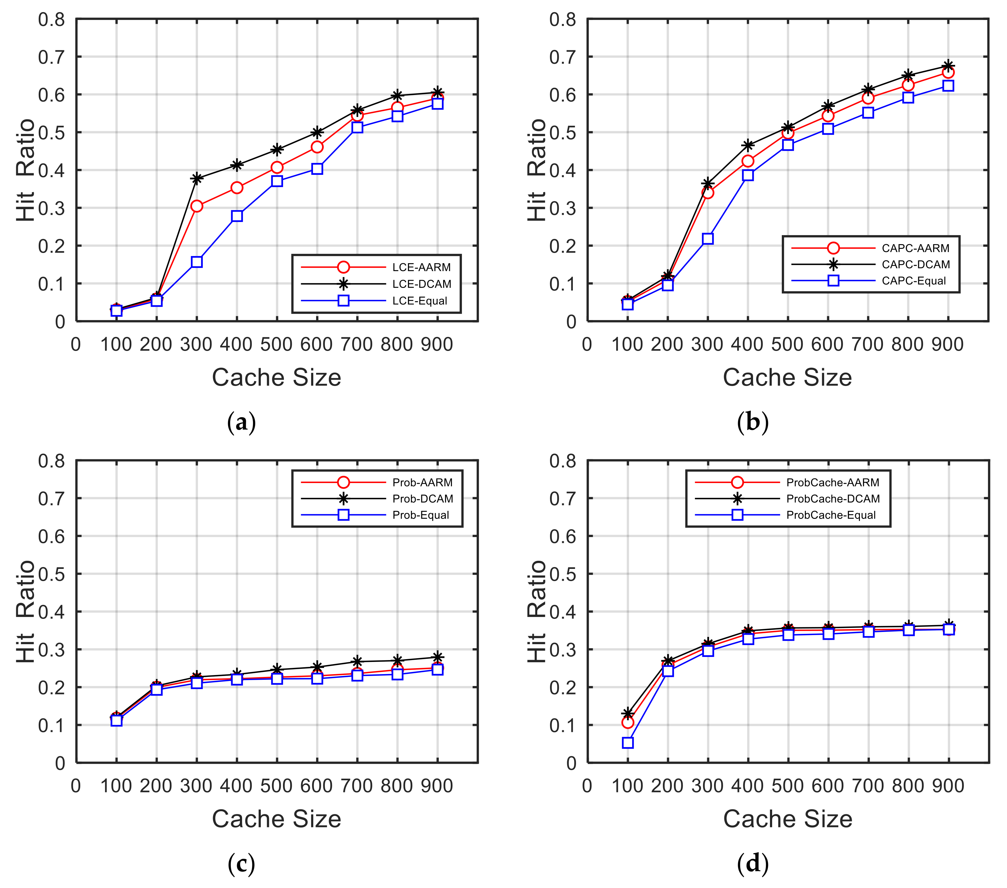
5.3. Average Cache Hit Ratio

After a cache hit, the cache node immediately retransmits the lost data. The cache hit ratio is defined as the number of NACKs recovered divided by the total number of NACKs received in a cache node, which reflects the overall cache resource utilization of the multicast tree nodes. Figure 5 shows the variation of the average hit ratios of all MTNs against different cache space sizes in the combinations of different cache allocation mechanisms and different cache strategies.
As can be seen from Figure 5, the cache hit ratios of all combinations become greater with the cache size increasing, which is in line with the expectation that more chunks can be cached in larger cache space. Among them, the combinations of DCAM and all cache strategies achieve the highest cache hit ratio, because the DCAM evaluates the cache requirements of the multicast group according to the change of the packet loss probability, node depth, and transmission rate, and can adjust the allocation results in time. Based on the allocation result of AARM, the cache hit ratios achieved by each cache strategy are the second. The cache hit ratios achieved by each cache strategy based on the allocation result of Equal are the worst.
Based on the same cache quota, LCE shows the same trend as CAPC, but it has a lower cache hit ratio. ProbCache and Prob have the worst performance because they just randomly cache chunks and do not care if cached chunks will be lost. Under the same cache quota, CAPC can cache chunks that experience congestion loss with a high probability, and most of the lost data can be recovered through MTNs instead of multicast source. Therefore, CAPC has the highest cache hit ratio.
Therefore, this section verifies the effectiveness of DCAM in the scenario where multiple multicast groups share cache resources, and the combination of DCAM and CAPC can achieve optimal cache resource utilization.

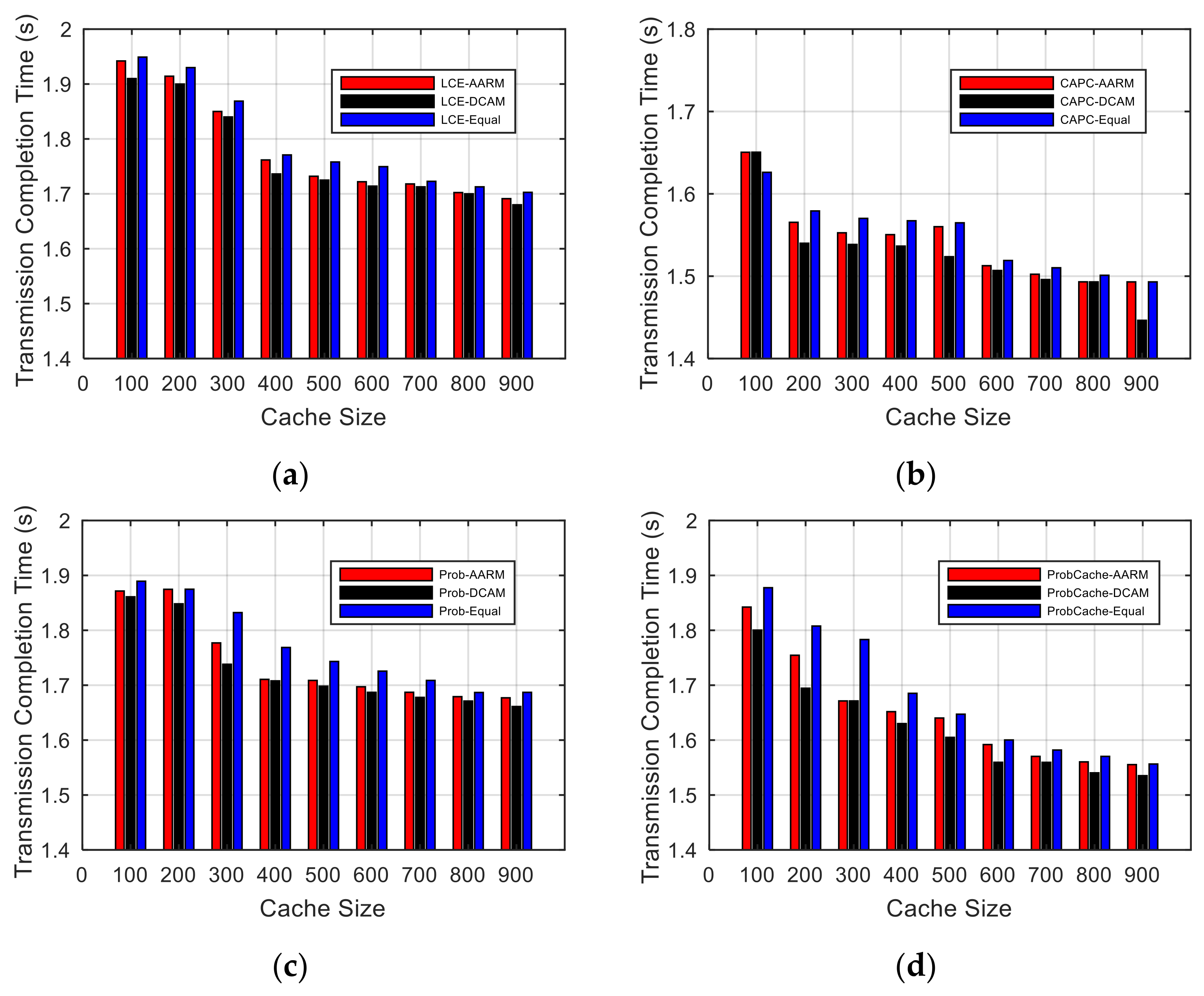
5.4. Average Transmission Completion Time

In this section, we count the average transmission completion time achieved by the combinations of each cache allocation mechanism and each cache strategy, including the time spent in the recovery phase. Graphics given in Figure 6 illustrate the variation of average transmission completion time against different cache size.
As the cache size increases, more chunks are cached by the MTNs, and the loss recovery delay decreases, so the average transmission completion time achieved by various combinations decreases. Under the same cache strategy, the DCAM can achieve a lower average transmission completion time than other cache allocation mechanisms, which shows that the DCAM is more reasonable. In addition, in Figure 6b, when the cache allocation mechanism adopts DCAM and the cache strategy adopts CAPC, the lowest average transmission completion time can be achieved. It can be seen that this performance comparison result is consistent with the conclusion of the NLRD comparison.

5.5. Overhead Evaluation

The reliable multicast loss recovery process includes the feedback and retransmission stages, which cause extra processing overhead to the MTNs. The cache allocation result will affect the overall recovery process of the reliable multicast groups. Therefore, we measure the reasonableness of the cache allocation mechanism in terms of request overhead and recovery overhead. In this paper, the NACK feedback aggregation and recovery isolation mechanism proposed by [20] is used in the implementation of the reliable multicast loss recovery method. We separately count the number of upstream and downstream packets (excluding original multicast data packets) processed by each MTN, and calculate the average of all MTNs. Let the ratio of the above average number of processed packets to the number of original multicast packets sent by the source denote the upstream overhead and the downstream overhead, respectively. This result represents the number of upstream and downstream packets required to reliably deliver a certain number of original multicast packets to the multicast group, respectively.

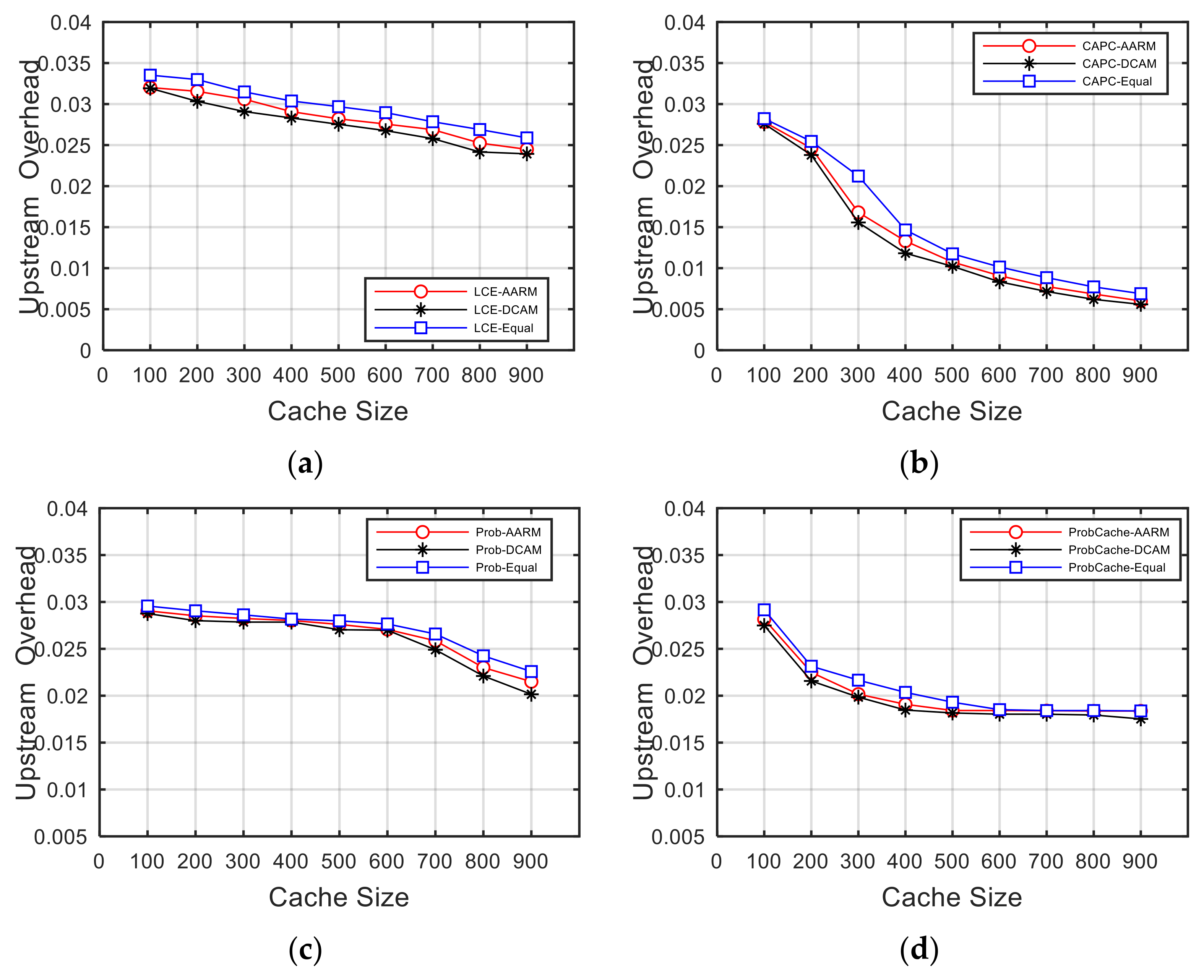
5.5.1. Upstream Overhead

In the case of packet loss, the packets sent upstream by the MTNs and the receivers are NACK packets. As shown in Figure 7, all the upstream overhead curves show a downward trend with increasing cache size, because more and more recovery packets are retransmitted by MTNs. It is worth noting that when the cache size is larger than 600, the upstream overhead curve in Figure 7c starts to drop significantly. When the cache size is less than 500, the upstream overhead curve in Figure 7d decreases significantly, while when the cache size is greater than 500, the curve is in a stable state. The upstream overhead curve in Figure 7b has the largest drop, which shows that caching chunks of each multicast group based on the DCAM allocation result can achieve the lower upstream overhead in the process of reliable multicast loss recovery.

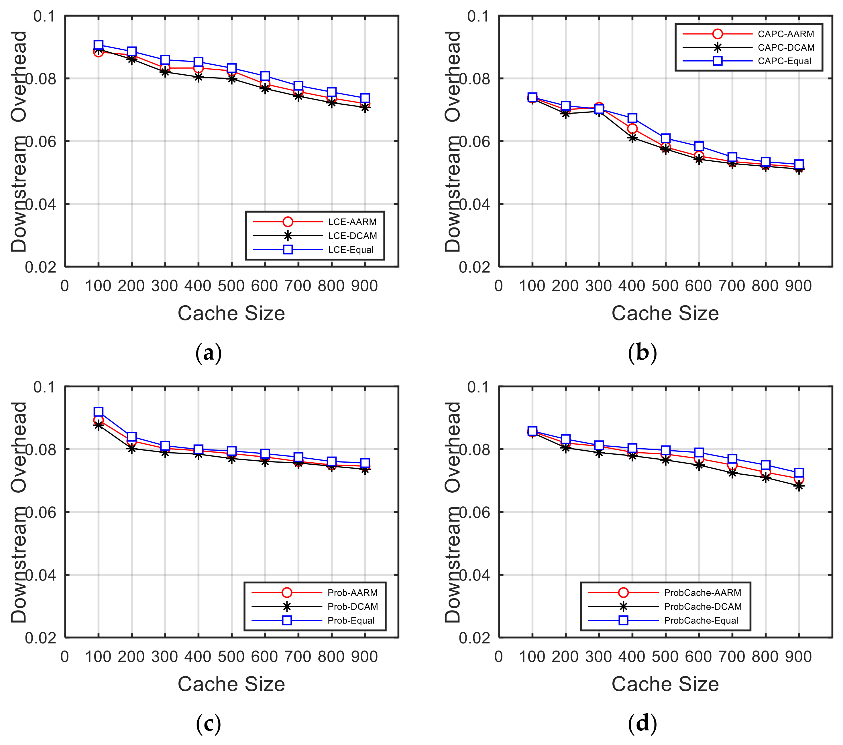
5.5.2. Downstream Overhead

In the case of loss recovery, the packets sent downstream by the MTNs are recovery packets. As shown in Figure 8, as the cache size increases, more chunks are cached, and the downstream overhead generated by all combinations decreases. Under the same cache strategy, compared with AARM and Equal, using DCAM to allocate the cache resources of the MTNs can achieve smaller downstream overhead. Among them, the DCAM-CAPC combination is always more advantageous than other combinations. For example, when the cache size is 900, the downlink overhead achieved by the DCAM-CAPC combination is 27.75%, 30.56% and 25.19% lower than that of DCAM-LCE, DCAM-Prob, and DCAM-ProbCache, respectively.
The experiment results in this section reflect the advantages of DCAM in reducing the overall overhead in the process of reliable multicast loss recovery, and reflect that the allocation mechanism is more reasonable than AARM and Equal.

6. Conclusions

For the scenario where there are multiple reliable multicast groups in ICN and the cache resources of multicast tree nodes are shared by those groups, this paper designs a dynamic cache allocation mechanism (DCAM) to reduce the overall loss recovery delay of reliable multicast. DCAM considers three factors such as packet loss probability, node depth, and transmission rate, and defines them as NACK weight, distance weight, and rate weight, and finally allocates cache space for multicast groups according to the normalized cache quota weight. We implement this mechanism in NS-2 and evaluate its performance. Combining the DCAM, AARM, and Equal cache allocation mechanisms with LCE, CAPC, ProbCache, and Prob cache strategies respectively, we compare and analyze the loss recovery delay, cache hit ratio, transmission completion time, and overhead. Experimental results show that DCAM can adjust cache allocation results in time according to network changes, and its combinations with various cache strategies outperform other combinations. Based on the cache allocation results of DCAM, the optimal results can be achieved by using CAPC cache strategy, and its recovery delay is 3.2–31.44% lower than other combinations.

Author Contributions

Conceptualization, Y.D., H.N. and X.Z.; Methodology, Y.D., H.N. and X.Z.; Software, Y.D.; Writing—original draft preparation, Y.D.; Writing—review and editing, Y.D., H.N. and X.Z.; Supervision, X.Z.; Project administration, X.Z.; Funding acquisition, H.N. All authors have read and agreed to the published version of the manuscript.

Funding

This work was funded by Strategic Leadership Project of Chinese Academy of Sciences: SEANET Technology Standardization Research System Development (project no. XDC02070100).

Institutional Review Board Statement

Not applicable.

Informed Consent Statement

Not applicable.

Data Availability Statement

Data sharing not applicable.

Acknowledgments

We would like to express our gratitude to Jinlin Wang and Rui Han for their meaningful support of this work.

Conflicts of Interest

The authors declare no conflict of interest.

References

  1. Pan, J.; Paul, S.; Jain, R. A survey of the research on future internet architectures. IEEE Commun. Mag. 2011, 49, 26–36. [Google Scholar] [CrossRef]
  2. Xylomenos, G.; Ververidis, C.N.; Siris, V.A.; Fotiou, N.; Tsilopoulos, C.; Vasilakos, X.; Katsaros, K.V.; Polyzos, G.C. A survey of information-centric networking research. IEEE Commun. Surv. Tutor. 2013, 16, 1024–1049. [Google Scholar] [CrossRef]
  3. Ahlgren, B.; Dannewitz, C.; Imbrenda, C.; Kutscher, D.; Ohlman, B. A survey of information-centric networking. IEEE Commun. Mag. 2012, 50, 26–36. [Google Scholar] [CrossRef]
  4. Jiang, X.; Bi, J.; Nan, G.; Li, Z. A survey on information-centric networking: Rationales, designs and debates. China Commun. 2015, 12, 1–12. [Google Scholar] [CrossRef]
  5. Liao, Y.; Sheng, Y.; Wang, J. Summary of Research on ICN Name Resolution Technology. J. Netw. New Media. 2020, 9, 9. [Google Scholar]
  6. Adhatarao, S.S.; Chen, J.; Arumaithurai, M.; Fu, X.; Ramakrishnan, K.K. Comparison of naming schema in ICN. In Proceedings of the 2016 IEEE international symposium on local and metropolitan area networks (LANMAN), Rome, Italy, 13–15 June 2016; pp. 1–6. [Google Scholar]
  7. Yamamoto, M. A survey of caching networks in content oriented networks. IEICE Trans. Commun. 2016, 99, 961–973. [Google Scholar] [CrossRef] [Green Version]
  8. Yang, B.; Chen, X.; Xie, J.; Li, S.; Zhang, Y.; Yang, J. Multicast Design for the MobilityFirst Future Internet Architecture. In Proceedings of the 2019 International Conference on Computing, Networking and Communications (ICNC), Honolulu, HI, USA, 18–21 February 2019; pp. 88–93. [Google Scholar]
  9. Zhang, L.; Afanasyev, A.; Burke, J.; Jacobson, V.; Claffy, K.C.; Crowley, P.; Papadopoulos, C.; Wang, L.; Zhang, B. Named data networking. ACM SIGCOMM Comp. Commun. Rev. 2014, 44, 66–73. [Google Scholar] [CrossRef]
  10. Wang, J.; Chen, G.; You, J.; Sun, P. SEANet: Architecture and Technologies of an On-site, Elastic, Autonomous Network. J. Netw. New Media 2020, 9, 8. [Google Scholar]
  11. Raychaudhuri, D.; Nagaraja, K.; Venkataramani, A. Mobilityfirst: A robust and trustworthy mobility-centric architecture for the future internet. ACM SIGMOBILE Mob. Comput. Commun. Rev. 2012, 16, 2–13. [Google Scholar] [CrossRef]
  12. AbdAllah, E.G.; Hassanein, H.S.; Zulkernine, M. A survey of security attacks in information-centric networking. IEEE Commun. Surv. Tutorials 2015, 17, 1441–1454. [Google Scholar] [CrossRef]
  13. Chakraborty, D.; Chakraborty, G.; Shiratori, N. A dynamic multicast routing satisfying multiple QoS constraints. Int. J. Netw. Management. 2003, 13, 321–335. [Google Scholar] [CrossRef]
  14. Kawasumi, R.; Hirota, Y.; Murakami, K.; Tode, H. Multicast distribution system with functions of time-shift and loss-recovery based on in-network caching and openflow control. In Proceedings of the 8th International Conference on P2P, Parallel, Grid, Cloud and Internet Computing, Compiegne, France, 28–30 October 2013; pp. 641–646. [Google Scholar]
  15. Whetten, B.; Vicisano, L.; Kermode, R.; Handley, M.; Floyd, S.; Luby, M. Reliable multicast transport building blocks for one-to-many bulk-data transfer. RFC 3048. Available online: https://tools.ietf.org/html/rfc3048 (accessed on 1 January 2020).
  16. Zhang, J.; Li, Z.; Chen, Y.; Cheng, Y.; Ding, G. AACP: Adaptive Active Cache Management Protocol in Reliable Multicast Networks. J. Sichuan Univ. 2010, 42, 179–184. [Google Scholar]
  17. Xu, C.; Lv, S. Research on Cache Size Allocation Scheme Based on Node Weight in ICN. Res. Comput. Appl. 2017, 34, 214–216. [Google Scholar]
  18. Zhang, J.; Li, Z.; Chen, L. Dynamic cache allocation algorithm and replacement policy for reliable multicast network. In Proceedings of the 5th International Conference on Wireless Communications, Networking and Mobile Computing, Beijing, China, 24–26 September 2009; pp. 1–5. [Google Scholar]
  19. Yeung, K.L.; Wong, H.-L.T. Caching policy design and cache allocation in active reliable multicast. Comput. Netw. 2003, 43, 177–193. [Google Scholar] [CrossRef]
  20. Duan, Y.; Ni, H.; Zhu, X. Reliable Multicast Based on Congestion-Aware Cache in ICN. Electronics 2021, 10, 1579. [Google Scholar] [CrossRef]
  21. Psaras, I.; Chai, W.K.; Pavlou, G. Probabilistic in-network caching for information-centric networks. In Proceedings of the 2nd Edition of the ICN Workshop on Information-Centric Networking, Helsinki, Finland, 17 August 2012; pp. 55–60. [Google Scholar]
  22. Laoutaris, N.; Syntila, S.; Stavrakakis, I. Meta algorithms for hierarchical web caches. In Proceedings of the IEEE International Conference on Performance, Computing, and Communications, Phoenix, AZ, USA, 15–17 April 2004; pp. 445–452. [Google Scholar]
  23. Feng, G.; Zhang, J.; Xie, F.; Siew, C.K. Buffer management for local loss recovery of reliable multicast. In Proceedings of the IEEE Global Telecommunications Conference, Dallas, TX, USA, 29 November–3 December 2004; pp. 1152–1156. [Google Scholar]
  24. Wang, J.; Li, C.; Huang, J. A Survey of Research on the Strategies for Setting the Cache Size of Routers. Comput. Sci. 2009, 36, 12–16. [Google Scholar]
  25. Ge, G.; Guo, Y.; Lan, J.; Liu, C. Dynamic Secondment Mechanism of Cache Space Based on Replacement Rate in CCN. J. Commun. 2015, 36, 120. [Google Scholar]
  26. Cheng, D.; Liu, Z. A New Cache Space Dynamic Allocation Mechanism and Its Packet Loss Rate Analysis. Electron. J. 2001, 29, 634. [Google Scholar]
  27. Maravelakis, P.E.; Castagliola, P. An EWMA chart for monitoring the process standard deviation when parameters are estimated. Comput. Stat. Data Anal. 2009, 53, 2653–2664. [Google Scholar] [CrossRef]
  28. NS-2 Simulator [EB/OL]. Available online: https://www.isi.edu/nsnam/ns/ns-build.html (accessed on 1 March 2022).
Figure 1. A three-layer multicast tree model.
Futureinternet 14 00105 g001
Figure 2. The simulation topology.
Futureinternet 14 00105 g002
Figure 3. Experiments on the setting of weight coefficients values.
Futureinternet 14 00105 g003
Figure 4. Comparison of normalized loss recovery delay (NLRD). (a) Comparison of NLRD under LCE; (b) comparison of NLRD under CAPC; (c) comparison of NLRD under Prob; (d) comparison of NLRD under ProbCache.
Futureinternet 14 00105 g004
Figure 5. Comparison of average cache hit ratio. (a) Comparison of average cache hit ratio under LCE; (b) comparison of average cache hit ratio under CAPC; (c) comparison of average cache hit ratio under Prob; (d) comparison of average cache hit ratio under ProbCache.
Futureinternet 14 00105 g005
Figure 6. Comparison of average transmission completion time. (a) Comparison of average transmission completion time under LCE; (b) comparison of average transmission completion time under CAPC; (c) comparison of average transmission completion time under Prob; (d) comparison of average transmission completion time under ProbCache.
Futureinternet 14 00105 g006
Figure 7. Comparison of upstream overhead. (a) Comparison of upstream overhead under LCE; (b) comparison of upstream overhead under CAPC; (c) comparison of upstream overhead under Prob; (d) comparison of upstream overhead under ProbCache.
Futureinternet 14 00105 g007
Figure 8. Comparison of downstream overhead. (a) Comparison of downstream overhead under LCE; (b) comparison of downstream overhead under CAPC; (c) comparison of downstream overhead under Prob; (d) comparison of downstream overhead under ProbCache.
Futureinternet 14 00105 g008
Table 1. Experiment parameters.
ParameterValue
The   maximum   queue   length   ( Q m a x )700 packets
The   upper   threshold   for   queue   length   (   Q h i g h ) 0.75 × Q m a x
The   lower   threshold   for   queue   length   (   Q l o w ) 0.25 × Q max
Cache size100–900
Chunk size10 packets
Packet size1032 bytes
Weighting   factor   θ for DCAM0.9
The cache allocation cycle0.07 s
Cache   probability   threshold   ( P t h ) for CAPC0.4
Publisher’s Note: MDPI stays neutral with regard to jurisdictional claims in published maps and institutional affiliations.

