Abstract
In previous investigations, controllers for the track-keeping of ships were designed with the assumption of constant ship speed. However, when navigating in a fairway area, the ship’s speed is usually decreased to prepare for berthing. The existing track-keeping systems, which are applied when the ship navigates in the open sea with a constant ship speed, cannot be used to navigate the ship in the fairway. In this article, a support system is proposed for ship navigation in the fairway. This system performs three tasks. First, the ship is automatically controlled by regulating the rudder to follow planned tracks. Second, the ship’s speed is reduced step by step to approach the berth area at a low speed. Finally, at low speed, when the ship’s rudder is not effective enough to control the ship’s heading to a desired angle, the ship’s heading is adjusted appropriately by the bow thruster before changing the control mode into the automatic berthing system. By the proposed system, the automatic systems can be combined to obtain a fully automatic system for ship control. To validate the effectiveness of this proposed system for automatic ship navigation in the fairway, numerical simulations were conducted with a training ship model.
1. Introduction
Marine navigation plays an important role in maritime transportation and sea environment protection. To ensure ships’ operation safely and effectively from berth to berth, modern equipment has been produced to assist the deck officers in ship control and maneuvering. In fact, the ship navigation process includes three stages. First, the ship is navigated by autopilot to keep the ship heading on the desired course, and the autopilot is usually adjusted manually to track the planned route; this stage is conducted in open sea at the full speed of the main engine and is subject to an insignificant effect of waves. Second, the ship is controlled by the helmsmen in the fairway of the port area to continue on the planned track. In this stage, the ship’s speed is decreased at an appropriate time so that the ship is led to a certain area. In the last step of this stage, the ship heading is brought into the desired one before performing the berthing process. Finally, the ship is maneuvered into the berth by changing the rudder angle and propeller revolution simultaneously. In the second and third stages, the control process for ship navigation is fully operated by the navigators. With the development of a global economy, new requirements have been introduced into shipping transport, such as the optimization of the amount of crew on board, energy saving, and cost reductions in ship operation. For that purpose, the automation of ship operation is a feasible solution to reduce the amount of crew and operation cost. To date, many reports have been undertaken regarding the automation of the issues of ship motion control, such as ship course keeping, track-keeping, automatic berthing, automatic collision avoidance, and so on. This research is seen as the basis for automatic machines and systems in the real world for maritime applications.
The first automatic steering mechanism for ships was introduced by Sperry in 1911 [1], and the proportional-integral-derivative (PID)-based autopilot was constructed in 1922 by Minorski [2]. The task of this autopilot is the course-keeping control of ships. To enhance the performance of this function, different theories of control engineering were proposed, such as artificial neural networks, fuzzy logic, the back-stepping algorithm, sliding mode control, adaptive control, optimal control, and so on. However, these course-keeping systems have no ability to track a predetermined route, especially under strong external disturbance. In fact, navigators have to set a new course for the autopilot manually rather than automatically. To obtain the track-keeping ability from the course-keeping function for ship control systems, the drift distance determined from the ship to the route needs to be described when designing the controller. In addition, this function was also developed for unmanned surface vehicles. However, when designing the controller, these control systems either simplified ship dynamic models or considered the ship speed as a constant value. Therefore, these systems are only employed to follow a ship’s route in open sea, and they have difficulty in satisfying the demand of track-keeping systems of ships in maritime practice when ships navigate in a fairway area. On the other hand, since the ship motion is complex at low speed, the berthing control system needs exact controllers to regulate the rudder and propeller simultaneously. To assist the ship in maneuvering processes at low speed, auxiliary devices, such as bow thrusters and azimuth propellers are installed in ships to increase their maneuverability.
As summarized above, there are two main systems proposed to navigate the ship automatically; these are the track-keeping control system of a ship in the open sea and the automatic berthing system of the ship. The ship’s speeds in the automatic berthing system are absolutely different to those in the track-keeping system in the open sea. Therefore, to achieve a fully automatic system for ship navigation in future, an automatic navigation system of a ship in the fairway is needed in combination with the above-mentioned systems, which is proposed in this study. This system, is illustrated as in Figure 1, performs three tasks: First, the ship’s rudder is automatically controlled by a fuzzy logic controller to track the planned route; second, the ship’s speed is decreased by the PID controller to approach the berth area at a low speed; finally, when the ship’s rudder is not effective enough at a low speed to change the ship’s heading to the desired angle, the ship heading is adjusted appropriately by the bow thruster before berthing maneuvering. The bow thruster is also regulated by a second fuzzy controller. To illustrate the effectiveness of this system, numerical simulations were conducted with training ship of Mokpo Maritime University. The results showed that the proposed system has the performance necessary for automatic ship navigation in the fairway area.
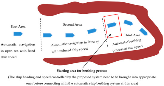
Figure 1.
Automatic navigation system of a ship in a fairway.
2. Literature
Since the PID algorithm-based autopilot was proposed in 1922 by Minorski [2], many different autopilots have been studied using modern control theories to improve the course-keeping quality. For example, the autopilots were considered based on fuzzy set theory [3], the neural networks combined with back-stepping algorithm [4,5,6], adaptive control [7], disturbance rejection control [8], and optimal control [9]. Course-keeping autopilots with the function of ship collision avoidance was suggested in References [10,11]. However, when there are external disturbances acting on the ship like wind, current and waves, course keeping autopilots have difficulties tracking the planned route, especially in strong disturbances. With the development of satellite guidance technology, track-keeping functions can be developed from course-keeping autopilots. For this purpose, the cross tracking error needs to be considered in the controllers. In research [12,13], precision maneuvering and adaptive autopilots were introduced for track-keeping. In References [14,15,16,17], the authors used neural networks to approach this problem. In studies [18,19,20], a sliding mode technique was applied through combination with a pre-filter and a high gain observer for damping the disturbance. In research [21,22], the controllers were enhanced to perform both track-keeping and roll reduction functions in ocean waves.
In comparison with others, fuzzy logic is considered a suitable approach because it has the ability to perform the wheel alteration of ship as helmsman’s action with the perception and inference of input levels. As suggested in research [23], the authors proposed the fuzzy track-keeping system by suggesting the use of two sub-autopilots. In this system, first the fuzzy controller is used to control the ship course, and a second one is employed to regulate the distance off-set. For more confidence, the track-keeping of the ship was, as shown in the experiment model [24]. To enhance the adaptive nature of the fuzzy system, the research shown in Reference [25] developed a track-keeping system with a Sugeno-type and adjustable scaling factors mechanism. Recently, the authors in Reference [26] also employed fuzzy track-keeping control in ship maneuvering systems. Although the above-mentioned systems obtained significant results for track-keeping, they were only constructed under the assumption that the ship’s speed is constant. This means that these track-keeping systems are only suitable on the open ocean – not for inland waterways or channels.
Concurrently, many studies regarding automatic berthing systems have been published based on intelligent control theory. The process of ship berthing is carried out at low speed, when ship maneuverability is reduced significantly. Automatic ship berthing is therefore usually regarded as a difficult issue in the field of ship control. One of the most promising applications to berthing automation is neural networks, which has the ability to perform the berthing steps similarly to how it is done by the human brain. Results in automatic berthing with parallel structures were proposed in Reference [27]. Later on, ship berthing was proposed with the assistance of bow thrusters and tugboats [28]. As developed by the authors in Reference [29], a virtual window was used to create instructive data for the controller. Berthing at different ports is recorded in References [30,31]. Another approach, which examined via the research in Reference [32], used an adaptive back-stepping control for a cruise ship under wind power. However, using a neural network or another approach for automatic ship berthing requires the ship’s speed to be necessarily low. Therefore, in order to adapt to automatic ship berthing systems and track-keeping systems on the open ocean, an automatic ship navigation system in the fairway environment is necessary. The proposed system has three tasks: (1) Tracking of the ship’s route in a fairway, (2) decreasing the ship’s speed, and (3) bringing the ship’s heading to the desired heading before starting the ship berthing process.
3. Mathematical Model of Ship Motion
3.1. Ship Kinematics
To determine the state of dynamic ship movement (position, heading, and velocity), kinematics equations are applied. These equations show the relationship of ship parameters in two reference frames: The Earth-fixed reference frame O-ηξ and the body-fixed reference frame G-xy. The origin of the body-fixed reference frame is placed at the center of gravity of the ship, as described in Figure 2. By neglecting ship motions in directions, such as heave, pitch, and roll, the transformation between these reference frames is expressed by Equation (1) as follows:
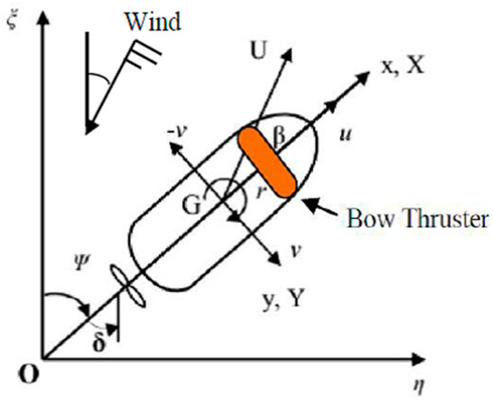
Figure 2.
Ship dynamic in Cartesian reference frame.
3.2. Ship Dynamic Model
To solve the problems of ship maneuvering or ship control systems, the mathematical model of the ship needs to be described first. This model has to represent the precise characteristics of the ship in the real world. Ship motions, such as surge, sway and yaw are enough to express the dynamic characteristics of the ship on the Cartesian coordinate system.
The Maneuvering Modeling Group (MMG) model has been employed in this research to show ship motion during the berthing process, in which the hydrodynamic components (forces and moments acting on the ship) were divided into separate modules, such as the hull, rudder, propeller, tugboat and thruster. According to MMG model, the maneuvering equation of the ship is shown as follows:
where u, v, and r are the ship’s velocity in the surge, sway and yaw directions, respectively; XH, YH, and NH are the hydrodynamic forces and moments acting on the ship’s hull. They are defined by the Kijima equations [33], employed as in Equation (3):
where are hydrodynamic coefficients which are assumed as the method described by the authors [33].
The longitudinal force of the propeller is determined as follows:
The hydrodynamic forces and moment by the rudder are expressed as:
where
Considering the dynamic model of the bow thruster on ship maneuvering, the method of Hawkins et al. [34] was proposed. This model was also employed in the research of Tran and Im [28]. The expression is shown as follows:
where T is the total lateral thrust of impeller and surface forces; wo and L are the rate of turn and length on the load water line; H is the ship’s draft; Mo is the rotation rate constant. Tf and TS are the outputs from the bow and stern thrusters, respectively, making the forces in the y-axis and moments in the z-axis yielded by the side thrusters expressed as:
In this research, the thruster is only used in bow positioning and the tugboat is made fast astern. Thus, the components and become zero in Equations (7) and (8), respectively.
In this study, in order to predict the hydrodynamic coefficients, the training ship (named SAENURI) of Mokpo National Maritime University was employed as the model ship. The particulars of this ship are shown in Table 1. Hydrodynamic coefficients predicted by the Kijima model are presented in Table 2.

Table 1.
Principle ship particulars.
Table 2.
Ship hydrodynamic coefficients.
3.3. The Effect of Wind
In a study performed by Isherwood [35], the effect of wind on merchant ships was carried out at different laboratories. Empirical formulas were derived in order to calculate the force and the moment on any merchant ship induced by wind. By applying these formulas, the coefficients are determined as follows:
where is the coefficient of the longitudinal component of the wind force; is the coefficient of the lateral component of the wind force; and is the coefficient of the wind-induced yawing moment. (~, ~, ~) are Isherwood’s coefficients in the above equations.
In order to define the wind-induced forces and moments acting on the ship, the following equations are used:
where, is the longitudinal component of wind force; is the lateral component of wind force; is the yawing moment; is the relative wind speed on the ship; and LOA is the overall length of ship.
In this research, ship motion is assumed to be affected by wind alone. However, in reality there are a number of different disturbances at work, such as currents and waves. Because the ship is navigating in a fairway, and free board is significantly more than the ship’s draft, the effects of current and waves can be ignored. In cases of tankers or bunker vessels, the effects of current and waves should be taken into account in the ship dynamic model. To determine the effects of current and waves on ship motion, one must calculate the forces and moments induced by these disturbances. They would then be placed into the right side of Equation (2).
4. Automatic Navigation System of a ship in a Fairway
4.1. The Concept of this System
In this research, the automatic ship navigation system is proposed to perform three tasks. First, the ship’s rudder is automatically controlled to keep it tracking the planned route. To carry out this task, the fuzzy logic controller is fed with two inputs and one output. The structure of the track-keeping system proposed in this research is the same as that of others in previous studies.
Second, ship speed is automatically controlled by a PID controller, and is decreased when the ship approaches the berthing area. The desired speed of the ship in each track is predetermined to ensure that the ship approaches the berthing area with the desired speed. PID algorithms will calculate the input signal to control propeller RPM.
Finally, to confirm the feasibility of such an automatic ship berthing system, the ship heading line needs to be adjusted to the appropriate direction concurrently with the adjustment of ship speed. Because the ship’s rudder is ineffective at low speed, the bow thruster is used for directional control instead of the ship’s rudder. The fuzzy logic is also designed with this in mind.
The system includes the following components: Ship Route Generator, Navigation Algorithms, a Decision-Making Block, and the Control System. The aim of these components is presented in the following section. The architecture of the automatic ship navigation system is shown in Figure 3.
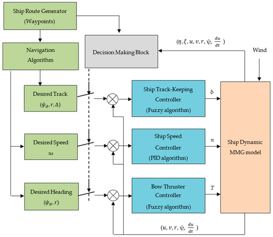
Figure 3.
The operational area of the automatic navigation system.
4.2. Ship Route Generator
Before beginning a voyage, deck officers must establish an optimal route for the whole voyage. Nowadays, with the development of science and technology, route planning for ship navigation can be conducted automatically when the navigators enter the departure and destination points in a personal computer. The role of this function is to create the waypoints (WPs) for of route. From these known waypoints, the desired course and speed are easily calculated. Then, in combination with track-keeping algorithms, the necessary rudder angles and ship speeds are captured in each segment of the planned route. In this research, this automatic navigation process for a ship in a fairway was performed by numerical simulations on a computer. Specifically, a fairway in the Mokpo area of South Korea was applied. For this purpose, a route with ten waypoints was created (waypoint No 1 (WP1) to waypoint No 10 (WP10)), as shown in Figure 4.
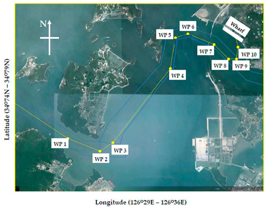
Figure 4.
The designed route of ship in fairway.
To be suitable for use in berthing, the ship’s speed must be reduced gradually to avoid damaging the main engine. In this study, the initial speed of the ship chosen in the numerical simulation was 8 knots, with a corresponding propeller index of 2.75 (round per second). From WP1 to WP4, the ship speed is maintained at 8 knots. From WP5 to WP8, the propeller index is decreased to 1.0 rps (as was of the actual aboard the T/S SAE NURI). Then, the ship’s propeller is stopped to affect the approach toward the WP10 area for berthing.
4.3. Navigation Algorithm and Decision Making Block
As shown in Figure 5, the task here is to calculate the desired variables, such as course (, distance between the ship and the relevant waypoint (d), and the distance from the ship to the current segment of the planned route (∆). The ship moves ahead on each segment from waypoint WPi-1(xd-1, yd-1) to waypoint WPi(xd, yd),. It is assumed that ship position at current time (t) is equal to OS(xt, yt). In this segment, the desired course angle () between the two waypoints WPi-1(xd-1, yd-1) and WPi(xd, yd) is:
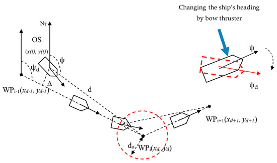
Figure 5.
The heading angle from ship to waypoint.
The cross track error from the ship to the current segment of the planned route (∆) is given by:
where x(t), y(t) are the ship position; a, b, c are coefficients of the line constructed by waypoints (WPi-1(xd-1, yd-1) and WPi(xd, yd)). The coefficients are defined as:
The distance between the ship and waypoint WPi(xd, yd) is calculated as follows:
The ship reaches the current waypoint (WPi) with a certain remaining distance (d). The distance (d0) determines the margin for the course change to the next waypoint. If the distance (d) is less than the fixed distance (d0), then the controller will alter the ship rudder angle to change the ship heading toward the next waypoint (WPi+1). By applying this rule, the ship course controller will change the ship course to the new waypoint.
To change the operating modes of the proposed system, the decision-making block is used. According to the correlation of ship position and ship track, this block chooses the corresponding controllers. For example, in (Figure 4), from waypoint No.1 to waypoint No. 6, only the track-keeping controller is used to control the ship with the rudder. From way-point No.6 to waypoint No. 9, the track-keeping controller and the speed controller are operated simultaneously. On the segment between way-point No.9 to waypoint No. 10, the heading stabilizing controller is activated to bring the ship heading to the desired angle for the berthing process.
4.4. Control System
4.4.1. Ship Track-Keeping Controller
For the track-keeping purpose of the ship, the fuzzy logic controller is designed using a Mamdani-type and bisector method. The proposed controller includes four sets of membership functions: Three for input signals and one for the output signal. The three inputs consist of the cross track error, the heading error, and the yaw rate of the ship. The output is the ship rudder angle. The parameters of this controller are shown in Table 3.
Table 3.
The parameters of track-keeping controller.
Input set 1: +VB (−VB) signifies a very big error from the route to the left (right); +B (−B): is big error; +M (−M): is medium error; Zero: is small error, see Figure 6a.
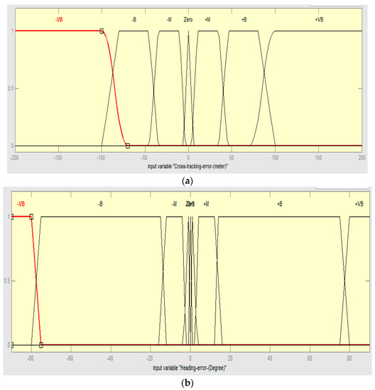
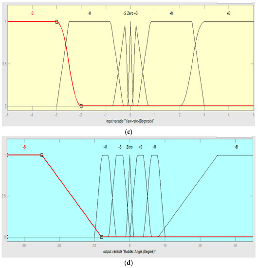
Figure 6.
Membership functions of three inputs and one output of track-keeping controller: (a) Cross tracking error; (b) heading error; (c) yaw rate; (d) rudder angle.
Input set 2: +VB (−VB) signifies as very big heading error to the port (starboard) side; +B (−B): is big heading error; +M (−M): is medium heading error; +S (−S): is small heading error; Zero: is very small heading error, see Figure 6b.
Input set 3: +B (−B) signifies a fast yaw rate to the starboard (port); +M (−M): is slow yaw rate; +S (−S): is very slow yaw rate; Zero: is small error, see Figure 6c.
Output set: +B (−B) signifies a big rudder angle to the starboard (port); +M (−M): is medium rudder angle; +S(−S): is small rudder angle; Zero: is rudder angle set to zero, see Figure 6d.
The inference knowledge of the track-keeping controller is established based on reasoning rules between the inputs and the output. These rules take the form of: IF…THEN…, for example:
IF (Cross track error is +VB) and (Heading error is +VB) and (Yaw-rate is −B)
THEN (Ship rudder angle is +B)
In this example, these rules can be understood as follows: When the ship is on left of the planned route with very big distance, and ship heading error is very large toward port side, and a fast ship yaw rate to port, then the ship’s rudder needs to be altered to hard starboard to bring the ship back onto the planned route as fast as possible and stabilize the ship’s heading on the route. In this study, 441 rules were constructed to perform the inference of the controller.
4.4.2. Ship Speed Controller
The aim of this controller is to gradually decrease the ship’s speed in each segment of the planned track. By using the PID (Proportional-Integral-Derivate) algorithm, as shown in Figure 7, the controller calculates the propeller signal for the ship dynamic model to obtain ship speed. According to the PID control theory, the error between the desired and actual speed is used as the input signal for the PID controller. The control signal (n) is the ship’s propeller RPM, and will be calculated and fed into the ship dynamics. By choosing suitable parameters for the controller (KP, Ki, Kd), PID control law ensures that the actual speed of the ship always follows the desired value.
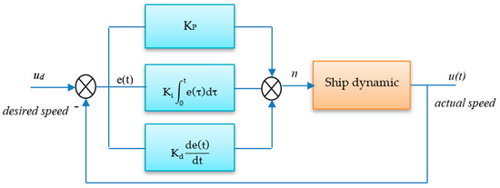
Figure 7.
The scheme of ship’s speed control using proportional-integral-derivative (PID) algorithm.
The error between the desired speed and actual one is defined as follows:
The PID control law is given as follows:
To determine the PID control parameters, several methods exist. The manual method, Nichols-Ziegler, genetic algorithm, etc. is one of them. Ship dynamics studied in this research has a high nonlinear in a 3DOF system, so the manual turning method is applied to determine the PID parameters.
In this research, Kp = −1; Ki = −0.05; Kd = −0.6 were determined by the manual method for gains of P, I, and D elements, respectively.
4.4.3. Heading Stabilizing Controller
Because the rudder at low speed is ineffective, the bow thruster is used to bring the ship’s heading onto the desired angle. To automatically control the ship’s heading by the bow thruster, a second fuzzy controller is also proposed. This controller includes two inputs and one output. The inputs consist of heading error and yaw rate while the output is the pushing force by the bow thruster. Each variable of the controller has seven membership function sets with variables: −B, −M, −S, Zero, +S, +M, and +B. The membership functions for these parameters are shown in Table 4. The membership functions of the controller are presented in Figure 8.
Table 4.
The parameters of heading controller.
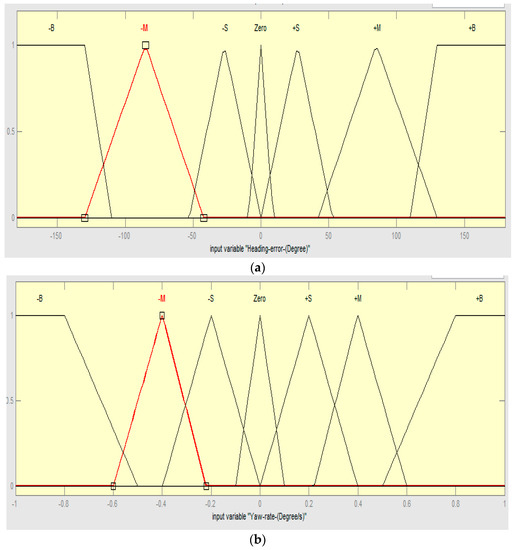
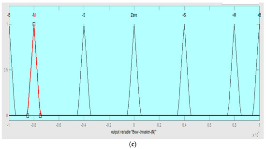
Figure 8.
The membership functions of the controller: (a) Heading error; (b) yaw rate; (c) bow thruster.
Input set 1: +B (−B) signifies a big heading error to the starboard (port) side; +M (−M): is medium heading error; +S (−S): is small heading error; Zero: is very small heading error, see Figure 8a.
Input set 2: +B (−B) signifies a fast yaw rate to the starboard (port); +M (−M): is slow yaw rate; +S (−S): is very slow yaw rate; Zero: is small error, see Figure 8b.
Input set 3: +B (−B) signifies a big force by bow thruster to push the ship’s bow from the port (starboard) to opposite side; +M (−M): is medium pushing force; +S (−S): is small pushing force; Zero: is pushing force set to zero, see Figure 8c.
Output set: Heading error range is limited from −180 to +180 degrees. The yaw rate is bounded from −1.0 degree/s2 to 1.0 degree/s2, and the output is determined from −10,000 N to 10,000N. In the membership functions for the pushing force of the bow thruster, there are seven triangle zones which are distributed symmetrically across a “0” value. Three zones at the negative axis are used to push the ship’s bow from starboard to port. To complete the design of the controller, 49 inference rules were built as Table 5.
Table 5.
The reasoning rules of heading controller.
5. Numerical Simulation and Result Discussion
5.1. The Conditions and Requirements of the Simulation
In this section, numerical simulations were carried out in MATLAB to verify the effectiveness of the proposed system for automatic ship navigation in a fairway environment. For simulation purposes, the latitude and longitude of the Mokpo area were normalized into non-dimensional units by using the equations given in (17):
Because the dimensions of the port area (longitude and latitude) and the length of the ship are shortened in computer simulations, the port area and ship length must be normalized into a non-dimensional form by dividing the latitude and longitude to the length of the ship (L). The geographical coordinates of Mokpo fairway area (Figure 4) and the ship position were normalized to non-dimensional form (non-dimensional unit) as the following form:
The non-dimensional area of the Mokpo fairway is shown in Figure 9. The planned route for ship navigation included waypoints which were marked by “plus” symbols.
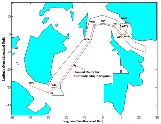
Figure 9.
Mokpo fairway simulation planned route after normalizing the latitude and longitude.
The details of these points are as follows: Waypoints (non-dimensional latitude, non-dimensional longitude) = (−29, −40); (−33, −30.3); (−30, −26); (−3, −7.3); (5.5, −5); (6.3, 0.5); (5, 6); (0, 10.5); (0, 12.5); and (4, 13.5). The initial position of the ship is located at a point having the coordinates (−48, −15) with 4 (m/s) in surge velocity and a propeller rev/sec of 2.75 (the effect of wind disturbance is assumed to be 5 knots in velocity from North (N) to South (S).
The proposed system consists of three functions with respect to ship control: First, the ship is brought to first waypoint WP1 to start the track-keeping process. The first fuzzy controller is activated to regulate the ship’s rudder and control the ship to track along the planned route from (WP1) to (WP10). Second, the propeller’s PRM is decreased from 2.75 to 0 (rps) by the PID controller when the ship arrives at waypoints (WP6, WP7, WP8, WP9), respectively. At waypoint (WP9), the ship’s engine is stopped so that the ship approaches (WP10) on only its own residual inertia. Finally, the heading stabilizing controller is employed to bring the ship’s heading onto 346.5 degrees (this direction is appropriate for approaching the wharf point from (WP9)). In this stage, the rudder’s effectiveness is not sufficient to turn the ship’s heading independently. Therefore, the bow thruster is proposed as an effective solution when the ship is difficult to control by rudder alone. After completing tasks of automatic ship navigation, this system can be combined with an automatic ship berthing system to bring the ship from area WP10 to the wharf point.
5.2. Automatic Ship Navigation in Fairway with the Proposed System
The results of the numerical simulation of the proposed system are shown in Figure 10, and the time history of the ship control process is presented in Figure 11. The ship at the start is very far from the first waypoint (WP1), so the ship’s heading was kept steady until the ship is at the first waypoint. For track-keeping via the proposed system, at the points (WP1), (WP2), the rudder was altered to port (−35°) to keep the ship on the route while the rudder was also changed to (+35°) to starboard at (WP5) and (WP7). In the segment between (WP3) and (WP4), the rudder was steady kept amidships by the track-keeping function of the system. At the waypoints (WP1), (WP2), (WP3), and (WP4), the yaw rate had negative values at these waypoints. At three times between (WP5) and (WP8), the yaw rate had positive values. The track cross error is maximum at the waypoints because the ship’s rudder is altered to the next waypoint when the ship is near to the current waypoint. With the ship is stable on the route, the track cross error converged to zero, (Figure 10). Meanwhile, for the function of speed reduction, from the sixth waypoint (at time = 1818 s), the propeller revolution was reduced to slow down the ships’ speed, and the main engine of the ship was stopped at the ninth waypoint (WP9). At the ninth waypoint (WP9), because the ship’s speed was low, the cross track error tended to increase even if the rudder was effective and was set to its maximum angle (−35°). It was difficult to keep the ship on this track (from (WP9 to WP10). In order to avoid a loss of control in this case, the bow thruster was activated by the heading stabilizing controller. The pushing force of the bow thruster was calculated based on the heading error and yaw rate. At time (2516 s), the heading error was a maximum (102°) to starboard, the yaw rate was −0.05 (°/s), and the bow thruster force was set to −8000 (N) to push the ship’s bow from starboard to port until the heading error converged to zero.
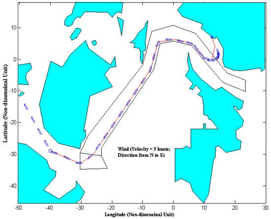
Figure 10.
The track of ship controlled by an automatic navigation system under the wind disturbance (velocity 5 knots, direction from N to S).
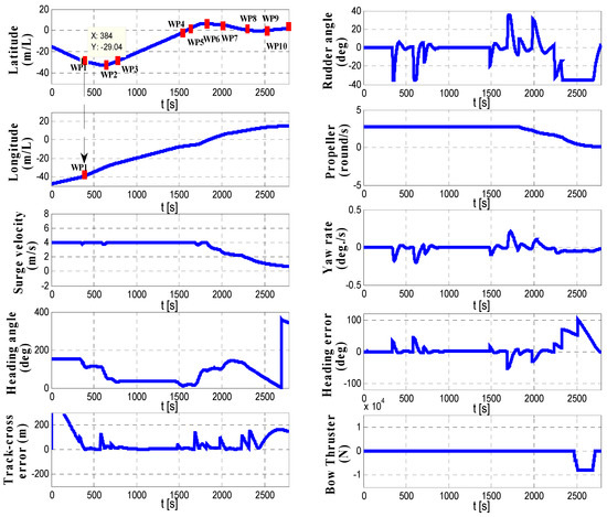
Figure 11.
The time history of ship motion controlled by the automatic ship navigation system.
After completing the automatic navigation process, the ship is brought to (WP10). At this point, the ship control process is changed into automatic berthing mode with low speed ship motion. The berthing problem noted in researches [27,28,29,30,31] can adapt to the proposed navigation system. In Figure 12, the automatic berthing process described in References [27,28,29,30,31] uses a neural network controller to regulate the rudder angle and the propeller revolution simultaneously.
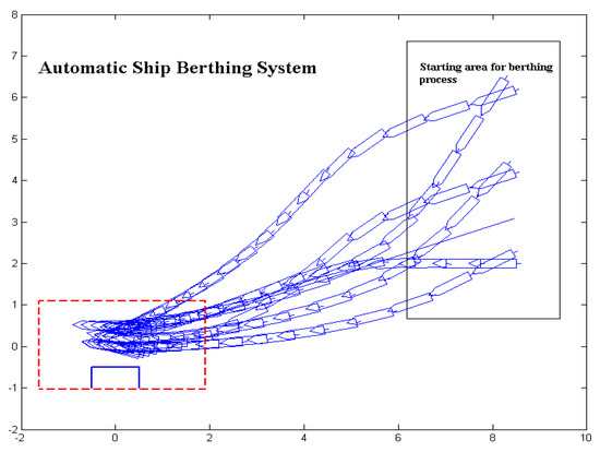
Figure 12.
The automatic ship berthing system using neural network controller.
5.3. Automatic Ship Navigation in a Fairway without the Heading Stabilizing Controller
As illustrated in Figure 13, the simulation was also carried out without the heading stabilizing function active. The performance of controlled ship motion from WP1 to WP9 is acceptable. However, the track cross error between (WP9 and WP10) is large when compared with Figure 10, and the ship exhibits an increased risk of collision with the wharf. In addition, the ship’s heading cannot track toward the wharf in this situation. In this case, it would be necessary to employ tugboats for ship berthing. Additionally, if the propeller revolution is not reduced when navigating in the fairway, the navigation process also exhibits an inability to approach the wharf area.
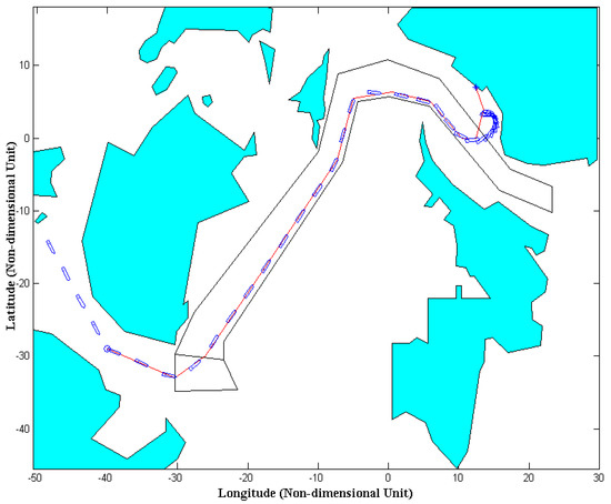
Figure 13.
The track of ship controlled by an automatic navigation system without the heading stabilizing controller.
6. Conclusions
In this investigation, the support system for automatic ship navigation in a fairway environment was proposed. Conclusions can be summarized as follows:
- This system is employed after the ship enters the fairway area and before the berthing process. This system is responsible for three tasks. The first task is automatically controlling the rudder to follow pre-planned tracks. The second is to decrease the ship’s speed to adapt to the automatic ship berthing system. Third, the ship’s heading is adjusted appropriately before the process.
- The proposed system includes two fuzzy controllers and one PID controller. The first fuzzy controller is applied to maintain ship track by changing the rudder angle while the second one is to stabilize the heading error. The PID controller is responsible for decreasing the ship’s speed by reducing propeller RPM. By this proposed system, the automatic control systems of the ship can be combined to obtain a fully automatic system for ship motion control.
- Numerical simulations were performed with the training ship from Mokpo Maritime University to validate the effectiveness of this system. The results showed the system yields acceptable performance for automatic ship navigation in a fairway area.
In the future, automatic functions for ship collision avoidance will be investigated and combined for this system.
Funding
This research received no external funding.
Acknowledgments
The author thanks the editors and three anonymous reviewers for their constructive comments, which helped us to improve the manuscript.
Conflicts of Interest
The author declares no conflict of interest.
References
- Sperry, E.A. Automatic steering. Trans. Soc. Nav. Archit. Mar. Eng. 1922, 30, 53–61. [Google Scholar]
- Minorski, N. Directional stability of automatically steered bodies. J. Am. Soc. Nav. Eng. 1922, 34, 280–309. [Google Scholar] [CrossRef]
- Amerongen, J.V.; Naute Lenke, H.R.; Veen der Van, J.C.T. An autopilot for ships designed by with fuzzy sets. In Proceedings of the IFAC Conference on Digital Computer Applications to Process Control, The Hague, The Netherland, 14–17 June 1997; pp. 479–487. [Google Scholar]
- Witkowska, A.; Smierzchalski, R. Designing a ship course controller by applying the adaptive backstepping method. Int. J. Appl. Math. Comput. Sci. 2012, 22, 985–997. [Google Scholar] [CrossRef]
- Witkowska, A.; Tomera, M.; Smierzchalski, R. A backstepping approach to ship course control. Int. J. Appl. Math. Comput. Sci. 2007, 17, 73–85. [Google Scholar] [CrossRef]
- Zhang, Q.; Jiang, N.; Hu, Y.; Pan, D. Design of course-keeping controller for a ship based on backstepping and neural networks. Int. J. e-Navig. Marit. Control 2017, 7, 34–41. [Google Scholar] [CrossRef]
- Du, J.; Abraham, A.; Yu, S.; Zhao, J. Adaptive dynamic surface control with Nussbaum gain for course keeping of ships. Eng. Appl. Artif. Intell. 2014, 27, 236–240. [Google Scholar] [CrossRef]
- Liu, S.; Xu, C.; Wang, J. Disturbance rejection control for the course keeping of the fully submerged hydrofoil craft. In Proceedings of the 35th Chinese Control Conference (CCC), Chengdu, China, 27–29 July 2016; pp. 747–751. [Google Scholar]
- Olsder, G.J. On the time optimal course changing of ships. J. Eng. Math. 1969, 3, 137–150. [Google Scholar] [CrossRef]
- Hasegawa, K.; Kouzuki, A. Automatic Collision avoidance system for ships using fuzzy control. In Proceedings of the 8th Ship Control System Symposium, The Hague, The Netherlands, 6–9 October 1987; Volume 2, pp. 34–58. [Google Scholar]
- Hwang, C. The Integrated Design of Fuzzy Collision-Avoidance and H∞-Auto pilots on Ships. J. Navig. 2002, 55, 117–136. [Google Scholar] [CrossRef]
- Bertin, D. Track-keeping controller for a precision maneuvering autopilot. In Proceedings of the IFAC Conference Control Application in Marine Systems, Fukuoka, Japan, 27–30 October 1998; pp. 155–160. [Google Scholar]
- Borkowski, P. Adaptive system for steering a ship along the desired route. Mathematics 2018, 6, 196. [Google Scholar] [CrossRef]
- Chen, M.; Ge, S.S.; Choo, Y.S. Neural network tracking control of ocean surface vessels with input saturation. In Proceedings of the IEEE International Conference on Automation and Logistics, Shenyang, China, 5–7 August 2009; pp. 85–89. [Google Scholar]
- Liu, Y.C.; Liu, S.Y.; Wang, N. Fully-tuned fuzzy neural network based robust adaptive tracking control of unmanned underwater vehicle with thruster dynamics. Neurocomputing 2016, 196, 1–3. [Google Scholar] [CrossRef]
- Zhang, G.; Zhang, X.; Zheng, J. Adaptive neural path following control for underactuated ships in fields of marine practice. Ocean Eng. 2015, 104, 558–567. [Google Scholar] [CrossRef]
- Zhang, Y.; Hearn, G.; Sen, P. A neural network approach to ship track-keeping control. IEEE J. Ocean Eng. 1996, 21, 513–527. [Google Scholar] [CrossRef]
- Cheng, J.; Yi, J.; Zhao, D. Design of a sliding mode controller for trajectory tracking problem of marine vessels. IET Control Theory Appl. 2007, 1, 233–237. [Google Scholar] [CrossRef]
- Perera, L.; Soares, C.G. Pre-filtered sliding mode control for nonlinear ship steering associated with disturbances. Ocean Eng. 2012, 51, 49–62. [Google Scholar] [CrossRef]
- Qin, Z. Sliding-mode control of path following for underactuated ships based on high gain observer. J. Central South Univ. 2016, 23, 3356–3364. [Google Scholar] [CrossRef]
- Ming-Chung, F.; Jhih-Hong, L. On the track keeping and roll reduction of the ship in random waves using different sliding mode controllers. Ocean Eng. 2007, 34, 479–488. [Google Scholar]
- Ming-Chung, F.; Yu-Hsien, L.; Bo-Jhe, W. Applying the PD controller on the roll reduction and track keeping for the ship advancing in waves. Ocean Eng. 2012, 54, 13–25. [Google Scholar]
- Omerdic, E.; Roberts, G.N.; Vukic, Z. A fuzzy track-keeping autopilot for ship steering. J. Mar. Eng. Technol. 2003, 2, 23–35. [Google Scholar] [CrossRef]
- Morawski, L.; Pomirski, J. Ship track-keeping: Experiments with a physical tanker model. Control Eng. Pract. 1998, 6, 763–769. [Google Scholar] [CrossRef]
- Velagic, J. Adaptive fuzzy ship autopilot for Track-keeping. Control Eng. Pract. 2003, 11, 433–443. [Google Scholar] [CrossRef]
- Gierusz, W.; Nguyen, C.V.; Rak, A. Maneuvering control and trajectory tracking of very large crude carrier. Ocean Eng. 2007, 34, 932–945. [Google Scholar] [CrossRef]
- Im, N.K.; Hasegawa, K. A study on automatic ship berthing using parallel neural controller. J. Kansai Soc. Nav. Archit. Jpn. 2001, 2011, 65–70. [Google Scholar]
- Tran, V.L.; Im, N.K. A study on automatic berthing with assistance of auxiliary devices. Int. J. Nav. Archit. Ocean Eng. 2012, 4, 199–210. [Google Scholar] [CrossRef]
- Ahmed, Y.A.; Hasegawa, K. Automatic Ship Berthing using Artificial Neural Network Trained by Consistent Teaching Data using Non-Linear Programming Method. J. Eng. Appl. Artif. Intell. 2013, 26, 2287–2304. [Google Scholar] [CrossRef]
- Im, N.K.; Nguyen, V.S. Artificial neural network controller for automatic ship berthing using head-up coordinate system. Int. J. Nav. Archit. Ocean Eng. 2018, 10, 235–249. [Google Scholar] [CrossRef]
- Nguyen, V.S.; Do, V.C.; Im, N.K. Development of automatic ship berthing system using artificial neural network and distance measurement system. Int. J. Fuzzy Log. Intell. Syst. 2018, 18, 41–49. [Google Scholar] [CrossRef]
- Park, J.Y.; Kim, N. Design of an adaptive backstepping controller for auto-berthing a cruise ship under wind loads. Int. J. Nav. Archit. Ocean Eng. 2014, 6, 347–360. [Google Scholar] [CrossRef]
- Kijima, K.; Katsuno, T.; Nakiri, Y.; Furukawa, Y. On the maneuvering performance of a ship with the parameter of loading condition. J. Soc. Nav. Archit. Jpn. 1990, 168, 141–148. [Google Scholar] [CrossRef]
- Hawkins, S.; Taggart, R.; Hoyt, E.D. The Use of Maneuvering Propulsion Devices on Merchant Ships; Report RT-8518; Contract MA-3293; Robert Taggart, Inc.: Washington, DC, USA, 1965. [Google Scholar]
- Isherwood, R.M. Wind Resistance of Merchant Ship. Trans. RINA 1972, 115, 327–338. [Google Scholar]
© 2019 by the author. Licensee MDPI, Basel, Switzerland. This article is an open access article distributed under the terms and conditions of the Creative Commons Attribution (CC BY) license (http://creativecommons.org/licenses/by/4.0/).