You are currently viewing a new version of our website. To view the old version click .
Materials
  • Article
  • Open Access

2 January 2025

Enhancement of Air-Entrained Grout-Enriched Vibrated Cemented Sand, Gravel and Rock (GECSGR) for Improving Frost and Thawing Resistance in CSGR Dams

,
,
,
,
and
1
State Key Laboratory of Simulation and Regulation of Water Cycle in River Basin, China Institute of Water Resources and Hydropower Research (IWHR), Beijing 100038, China
2
School of Civil Engineering, Beijing Jiaotong University, Beijing 100044, China
3
State Key Laboratory of Hydraulic Engineering Simulation and Safety, Tianjin University, Tianjin 300072, China
*
Author to whom correspondence should be addressed.
This article belongs to the Special Issue Advanced Cement-Based Composite Materials and Composite Intelligent Design

Abstract

Cemented Sand, Gravel, and Rock (CSGR) dams have traditionally used either Conventional Vibrated Concrete (CVC) or Grout-Enriched Roller Compacted Concrete (GERCC) for protective and seepage control layers in low- to medium-height dams. However, these methods are complex, prone to interference, and uneconomical due to significant differences in the expansion coefficient, elastic modulus, and hydration heat parameters among CSGR, CVC, and GERCC. This complexity complicates quality control during construction, leading to the development of Grout-Enriched Vibrated Cemented Sand, Gravel, and Rock (GECSGR) as an alternative. Despite its potential, GECSGR has limited use due to concerns about freeze–thaw resistance. This project addresses these concerns by developing an air-entrained GECSGR grout formulation and construction technique. The study follows a five-phase approach: mix proportioning of C1806 CSGR; optimization of the grout formulation; determination of grout addition rate; evaluation of small-scale lab samples of GECSGR; and field application. The results indicate that combining 8–12% of 223 kg/m3 cement grout with 2–2.23 kg/m3 of admixtures, mud content of 15%, a marsh time of 26–31 s. and a water/cement ratio of 0.5–0.6 with the C1806 parent CSGR mixture achieved a post-vibration in situ air content of 4–6%, excellent freeze–thaw resistance (F300: mass loss <5% or initial dynamic modulus ≥60%), and permeability resistance (W12: permeability coefficient of 0.13 × 10⁻¹⁰ m/s). The development of a 2-in-1 slurry addition and vibration equipment eliminated performance risks and enhanced efficiency in field applications, such as the conversion of the C1804 CSGR mixture into air-entrained GECSGR grade C9015W6F50 for the 2.76 km Qianwei protection dam. Economic analysis revealed that the unit cost of GECSGR production is 18.3% and 6.33% less than CVC and GERCC, respectively, marking a significant advancement in sustainable cement-based composite materials in the dam industry.

1. Introduction

Based on the concept of Hardfill Dam and Trapezoidal Cemented Sand and Gravel (CSG) Dam, the concept of Cemented Sand Gravel and Rock Dam (CSGRD), a new type of dam, was proposed by Jinsheng Jia of China in 2004 [,,,]. CSGRD is an economical and sustainable type of dam with a character between an embankment (soil-rock) dam and a gravity dam [,,,,]. The technique further expands on the sizes of the local aggregates in trapezoidal CSG Dam by Japanese Engineers from 80 mm to 150 mm in dams and up to 300 mm in coffer dams with little or no screening increasing construction efficiency and saving cost relative to the former. Again, Cemented Artificial Sand, Gravel, and Rock (CASR), a subcategory of CSGRD, can be built in conditions for steep riverbeds or when local aggregates are not available and proven to be 10% more economical than CSGRD [,,].
According to SL674-14, the technical guidelines for Cemented Granular Materials issued by the Ministry of Water Resources of the Peoples’ Republic of China, the CSGR material is produced by achieving certain shear strength through the minimal cementation of sand, gravel, and rock aggregates in their rightful proportions. Through that, the compressive strength classes C1804, C1806, C1808, and C18010 for the dam body and C18015 and C18020 for Rich-Mix and Rich Slurry CSGR, respectively, can be produced successfully to meet project requirements [,,].
Unlike the Concrete dam, in which the body is designed to be watertight, the body of the CSGRD is similar to the Faced-Symmetrical Hardfill Dam (FSHD), and the CSG Dam is designed to provide structural support but has the potential to develop into seepage along its compacted layers just like Roller Compacted Concrete (RCC). Hence, it requires upstream protection and a watertight layer in conjunction with the grouting curtains, drain holes, cushion layers, etc., which control the seepage under the dam [,,].
The FSHD by France, the CSG Dam by Japanese Engineers, and the CSGRD by Jinsheng Jia of China form the new classification known as HCC, with each letter representing a dam in the order mentioned above []. The FSHD considers the usage of precast concrete and geomembranes to construct the upstream watertight layer, whilst the CSG is known for using Conventional Vibrated Concrete (CVC) [,]. CSGRD has also previously employed either CVC or Grout-enriched Roller Compacted Concrete (GERCC) with Grout-enriched Vibrated CSGR (GECSGR) or Rich-slurry CSGR sandwiched between the former layer and body of the dam in medium-height dams [,].
However, the construction of this structure is complex and has potential interferences. This complexity arises due to notable differences between CSGR and CVC or GERCC in the expansion coefficient, elastic modulus, and hydration heat parameters. Consequently, ensuring quality control during construction is often a cause for concern [,,].
Fortunately, in the search for methods to improve GECSGR, a previous study by Hazaree et al. (2011) demonstrated that it is possible to entrain air in standard Roller-Compacted Concrete (RCC) and achieve adequate freeze–thaw resistance. However, efforts by researchers and contractors to incorporate air-entraining admixtures into Grout-Enriched RCC (GERCC) to improve freeze–thaw resistance have been unsuccessful [,].
In addition, earlier research highlighted an early attempt at the Horseshoe Bend dam in New Zealand, where a freeze–thaw resistant facing was desired. To achieve this, the grout was heavily dosed with an air-entraining admixture to obtain 3–4% residual air in the GERCC facing. However, the initial trials failed because the grout became excessively foamy and could not penetrate the spread RCC layer [].
Furthermore, one of the most detailed studies on air-entrained GERCC, involving laboratory tests and field trials, was reported in a previous study. The laboratory tests evaluated grout formulations, dosage rates, and methods for combining the grout with RCC. These tests revealed that achieving a homogeneous mixture by placing the grout on the top or bottom of the RCC is very challenging. Additionally, when internal vibrators were used to mix the grout and RCC, the air content, and thus the freeze–thaw resistance, significantly decreased. Similar results were observed in field trials and separate field trials conducted by Tatro et al. (2008). These findings underscore the challenge of using air-entrained GERCC; current construction techniques require substantial vibration to ensure a homogeneous mixture. However, this vibration removes much of the entrained air from the grout, reducing its freeze–thaw resistance [,,].
According to Musselman et al. (2016), organic and synthetic air-entraining admixtures successfully achieved air contents between 15% and 25% at their maximum recommended dosages, with the synthetic admixture providing the most stable air content and superior freeze–thaw resistance. While the water-reducing admixture helped reduce bleed and permeability, it caused greater variability in air content, making it unsuitable for air-entrained grout-encapsulated RCC (GERCC). Water-repelling and efflorescence-controlling admixtures improved performance, with the saline-based version showing better freeze–thaw resistance, whereas the powder water-resisting admixture negatively affected air entrainment and was not recommended for GERCC [].
Because the cons of the previously adopted materials outweighed the pros, research is needed to evaluate various construction techniques to determine their impact on grout distribution within the CSGR and freeze–thaw resistance of air-entrained GECSGR. Another reason was to identify an optimum placement technique and vibration level that balances these factors. Researchers of RCC therefore suggested future studies exploring these parameters for different RCC mixtures. Additionally, the development of automated processes for grout placement, mixing with RCC, and consolidating the mixture to enhance the quality and consistency of GERCC was recommended [,].
Jia et al. (2016), after laboratory investigations, put forward that Rich-Mix CSGR and GECSGR of permeability grade and Frost resistance up to W12 (equivalent to a permeability coefficient of 0.13 × 10⁻³ m/s) and F300 (300 freeze–thaw cycles with mass loss less than 5% and initial modulus of 60%), respectively, can be employed for frost/thawing resistance, anti-seepage control, and anti-carbonation zones in CSGRD based on the project’s actual requirement. A novel approach was suggested based on the experiences from previous CSGR projects and GERCC, which is incorporating vibrated grout-enriched CSGR in constructing the protection and seepage control layer of the low-height (h < 15 m) CSGR dam for the first time. In that work, a slurry addition rate of 8–12% was proposed and tested, and a new 2-in-1 grout addition and vibratory equipment were developed with a grouting capacity of 12 m2/h alongside a new surface water stop structure for the structural joints (i.e., T-shaped waterstop structure with boding strength and water-pressure resistance of 1.8 MPa and 1.6 MPa, respectively, for the layer). This reduced the cost of the layer to 50% relative to CVC and GERCC previously employed in CSGRD construction [,].
To build on the milestone of the GECSGR, the next goal of the project was to develop a grout mixture and construction method that enables the creation of air-entrained GECSGR in situ. This section of the research consists of five phases to systematically accomplish this goal: (i) development of mix proportion for parent CSGR; (ii) optimizing the grout mixture, including the type and quantity of chemical admixtures; (iii) assessing small-scale lab samples of CSGR and grout mixed in a laboratory mixer; (iv) evaluating large-scale lab samples of CSGR and grout combined using real-world construction methods; (v) carrying out field application. The findings shall be compared to the performances when CSGR and grout are mixed in a lab mixer, considering a strong freeze–thaw resistance. The caution is in field applications, as the level of vibration needs to be carefully managed to maintain performance using the 2-in-1 grouting and vibrating equipment to yield air-entraining and excellent field results [,].
The Qianwei Navigation and Hydropower Hub Project is located in Sichuan Province, China, in the lower Minjiang River. It is part of a larger shipping and hydropower plan for the Leshan–Yibin region and is classified as a second-class, large-scale project. The project’s main objective is navigation while also supporting power generation, water supply, and irrigation for local development. The hub’s water level is 335 m, with a 228 million cubic meters reservoir capacity. A protection dam (a dike as shown in Figure 1) 2.76 km long and up to 15 m high is located 2 km upstream of the hub and is designed to withstand a 20-year flood. It is built on a 13 m thick layer of sand and gravel bed.
Figure 1. Cross-section of Qianwei CSGR Dike with GECSGR layer (courtesy of Wu et al., 2024) [].
Initially, a geotextile membrane core wall and rockfill dam were planned, but concerns about leakage and overtopping led to an alternative design: a Cemented Sand, Gravel, and Rock (CSGR) dam with a trapezoidal cross-section. The upstream slope ratio is 1:0.5 and the downstream slope is 1:0.7. The dam’s main body has a 180-day compressive strength of 4 MPa (C1804) of CSGR material, while the upstream protective layer, designed to resist seepage, has a 90-day compressive strength of 15 MPa (C9015W6F50), along with impermeability of W6 (permeability coefficient of 0.42 × 10⁻¹⁰ m/s) and frost resistance grade of F50 (50 Freeze–thawing cycles). T-shaped surface water stops are used for joint sealing between the dam and its foundation, which is composed of sand and gravel with drainage capacity, eliminating the need for a separate drainage layer. This innovation and application of air-entrained GECSGR to the Qianwei Dike has enhanced construction efficiency significantly while simultaneously reducing project costs [,]. It is worth noticing that the results discussed in this project will provide a reference for constructing more sustainable and economical CSGR dams and hydraulic structures in the future.

2. Materials and Methods

2.1. Raw Materials

2.1.1. Cement

The cement is P.O 42.5 ordinary Portland cement produced by Sichuan Qianwei Baoma Cement Co., Ltd., located in Leshan, Sichuan Province of China. The cement quality and chemical test results are listed in Table 1 and Table 2, respectively, and the cement mortar strength test results are shown in Table 3. It can be seen from both tables that the test results of the inspected properties meet the technical requirements specified in GB175-2020 “General Purpose Portland Cement” [] (ASTM C150 equivalent) [].
Table 1. Cement quality test results.
Table 2. Cement chemical analysis.
Table 3. Cement mortar strength test results.

2.1.2. Fly Ash

The fly ash is grade II ash provided by Leshan Runsen Waste Recycling Co., Ltd. in Leshan, a community in China. The physical and chemical characteristics are shown in Table 4 and Table 5, respectively. In Table 4, the fineness is determined by screening fly ash through a 45 µm square hole sieve, and the fineness of the fly ash samples is expressed by the mass percentage of the sieve residue on the sieve. The water demand ratio is the ratio of the water demand of CSGR materials prepared with fly ash compared to specimens without fly ash (control) (ASTM C618) []. The strength activity index was also obtained by the measurement of the compressive strength of the test mortar and the control mortar after 28 days, and finally, the activity of the test mortar was determined by the ratio of the compressive strength of the two. The tables show that the test results of the tested performance comply with GB/T1596-2017 []. Class II fly ash coal ash requirements (ASTM C618 equivalent) [].
Table 4. Fly ash performance test results.
Table 5. Fly ash chemical analysis.

2.1.3. Chemical Admixtures

The six admixtures including organic air-entraining admixture (OAEA), synthetic AEA (SAEA), polycarboxylate-based water-reducing agent (WR), latex-based water-repelling and efflorescence-controlling admixture (LW), saline-based efflorescence-reducing and water-repelling admixture (SW) and a powdered water-resisting and superplasticizing admixture (PW) in Table 6 were provided by Shijiazhuang Mayor An Yucai Building Materials Co., Ltd. in Shijiazhuang, China. The performance test was carried out using the cement in Table 1. In Table 3, the results indicate that the admixture from the company and cement exhibited good compatibility. Also, in Table 6, the difference in setting time refers to the difference between the setting time of the CSGR with admixture and the control (i.e., those without admixtures) []. The ratio of compressive strength refers to the ratio between the compressive strengths of samples with admixture to those without admixture at different ages []
Table 6. Chemical and physical properties of admixtures.

2.1.4. Natural Aggregates

Riverbed sand, gravel, and rock aggregate from the upstream section of the Qianwei Navigation and Hydropower Hub Project were selected for particle screening tests. A total of 22 gradation tests were conducted on the aggregates, with particle sizes ranging from 150 to 80 mm, 80–40 mm, 40–20 mm, 20–5 mm, and below 5 mm. The gradation envelope for the gravel aggregate is shown in Figure 2, where G1 to G9 represent the different material gradations. For the composition of the gradation, the proportion of extra-large stones (80–150 mm) ranged between 16% and 32%, with an average of 22.3%. The proportion of large stones (40–80 mm) varied from 23% to 33%, with an average of 28.9%. Medium stones (20–40 mm) made up 17% to 19% of the total, averaging 18.9%. Small stones (5–20 mm) ranged from 7% to 14%, averaging 11.1%. Sand particles (less than 5 mm) varied from 10% to 29%, averaging 18.8%. Within the gradation envelope, the coarsest gradation had a sand content of 10.3%, while the finest gradation contained 28.1% sand. The average fineness modulus of the sand was 1.44, classifying it as super-fine sand, with an average mud content of 15% (% of natural aggregate passing sieve no. 200; plasticity (PI) < 17)% [,].
Figure 2. Particle size distribution curve of aggregates.

2.2. Methods

2.2.1. Phase 1: The Mix Proportion of CSGR

Based on the “double gradation and double strength” [,] principle proposed by Jinsheng Jia, the mixing material was prepared and controlled accordingly. The maximum coarse aggregate particle size was limited to 150 mm, while the cementitious material content was maintained at 80 kg/m3. The vibrating-compacted (VC) time at the mixer’s discharge was controlled between 2 and 8 s without admixture use. Detailed parameters are presented in Table 7, where schemes A1, B2, and C3 correspond to X1 aggregate (finest gradation with a sand ratio of 28.1%, and a distribution of extra-large stones/large stones/medium stones/small stones = 27.5:35.6:23.3:13.6), Y2 aggregate (average gradation with a sand ratio of 18.8%, and a distribution of extra-large stones:large stones:medium stones:small stones = 22.9:33.0:25.2:18.9) and Z3 aggregate (coarsest gradation with a sand ratio of 23.2%, and a distribution of extra-large stones:large stones:medium stones:small stones = 20.5:32.3:35.2:28.7), respectively. The gradation that produced Cemented Sand and Gravel (CSGR) laboratory compressive samples with a strength grade of C1806 (CSGR of compressive strength of 6 MPa after 180 days) at an 80–90% confidence rate was selected for the next phase.
Table 7. Mix proportion for C1806 CSGR production.

2.2.2. Phase 2: Grout Optimization

A standardized grout mixing procedure was implemented to assess the impact of chemical admixtures on the properties of grout. All grout formulations’ water-to-cement (w/c) ratio was fixed at 0.5–0.6 6. This w/c ratio was suggested considering previous experience with Grout Enriched Roller Grout Enriched CSGR and Compacted Concrete (GERCC). The chemical admixtures were initially mixed with water briefly before the gradual addition of cement. A paddle mixer, driven by a 1680 RPM drill, ensured consistent agitation during cement incorporation. Once all the cement had been added, the drill was operated at maximum speed for four (4) minutes to achieve a homogenous mix.
Upon completion of the four-minute mixing phase, the fluidity of each grout mixture was measured using the standard Marsh Funnel test according to ASTM D6910 [], and the time required for 946 mL of grout to pass through the funnel was noticed and recorded. Following the Marsh Funnel test, the air content of each mix was measured by ASTM C231/C231M [] using the Type-B pressure meter. A slight modification to the standard testing procedure was made to improve the accuracy of air content measurement by reducing foam presence in the pressure meter. Specifically, the grout was allowed to overflow the container slightly to eliminate excess foam, and a steel rod was used to strike off any remaining foam. This procedure was performed twice for each sample, followed by testing as per ASTM standards.
The remaining grout from each batch was allowed to sit undisturbed for 30 min. After this resting period, the grout was placed on a vibration table and subjected to one minute (60 s) of maximum intensity vibration, simulating the internal vibration of GECSGR during placement. The air content was then re-measured using the identical pressure method.
Six (6) Admixtures including organic air-entraining admixture (OAEA), synthetic AEA (SAEA), polycarboxylate-based water-reducing agent (WR), latex-based water-repelling and efflorescence–controlling admixture (LW), saline-based efflorescence–reducing and water-repelling admixture (SW), and a powdered water-resisting and superplasticizing admixture (PW). The water-repelling admixtures were specifically included to assess their influence on the stability of the air void system, as reducing permeability is a strategy to enhance freeze–thaw resistance. Initially, each admixture was evaluated independently at varying dosage levels, followed by combinations of admixtures to examine their interactions and effects on air matrix stability. A total of 37 grout formulations were tested, but 11 conditions of admixtures passed the above grout properties test using the methodology discussed above. The 11 with grout identity (ID) SL1 to SL11 are provided in Table 8 and proceeded for the GECSGR test [].
Table 8. Grout performance evaluations.

2.2.3. Phase 3: Determination of Grout Addition Rate

The grout addition rate was determined for grout formulated from Table 8 before application for both small and large-scale applications to determine the quantity of grout addition with respect to kg per m3 of CSGR. The performance indices for the selection were slump, compressive strength development, impermeability, and frost resistance. The mix for the grout is shown in Table 9.
Table 9. Grout formulated from Table 7 for grout addition rate test.

2.2.4. Phase 4: Small-Scale Laboratory GECSGR

In Phase 4, various fresh and hardened properties of CSGR, grout, and Grout-Enriched Vibrated CSGR (GECSGR) were analyzed. Tests included flow, air content, bleed, and compressive strength. Additionally, freeze–thaw resistance tests were conducted. Seven (7) chemical admixture combinations were evaluated for grout, including one grout mix without admixtures. These combinations were chosen based on Phase 2 and 3 results.
The CSGR mix was produced according to ACI 211.1 [] and fine-tuned through trial mixes, targeting a Vebe time of not exceeding 25 s (SL-678-14) []. Two 150 mm by 150 mm cubes were cast per mix for 28-day compressive strength tests after wet screening to remove aggregate greater than 40 mm, with compaction simulated by filling in thirds and compacting using a Hilti TE 805 hammer drill, as per ASTM C1435 []. A 75 mm by 100 mm by 400 mm rectangular prism was also cast for freeze–thaw resistance tests, compacted with a steel block struck with a rubber mallet.
The grout was mixed using a ChemGrout CG-600 colloidal grout plant, with 42.6 kg of cement per batch. After four minutes of mixing, the grout was transferred for testing. Immediate and 30 min delayed tests were performed for flow (ASTM D6910) [], specific gravity, and air content (ASTM C231) []. A Marsh Funnel test determined initial flow, while a mud balance measured specific gravity. Air content was checked using a Type B meter, and bleed stability was assessed using ASTM C1741 [], where air was pumped into a filtration funnel at 172 kPa to collect bleed water.
After 30 min, the grout was placed on a shake table and tested again for specific gravity and air content. Simulated field conditions involved circulating grout through the plant, constricting the valve to reach 345 kPa, and re-testing the material.
Grout-enriched CSGR was produced by adding grout to the remaining 79.4 kg of CSGR mix and mixing in a batch mixer. A Vebe test and unit weight measurement were conducted, and two cubes were cast. Freeze–thaw samples were prepared and tested as per ASTM C666 []. These samples, three enriched with grout and one standard CSGR, were cured for 14 days in lime water, then weighed and tested for fundamental transverse frequency every 30 freeze–thaw cycles [].

2.2.5. Phase 5: Field Application of GECSGR

The newly developed GECSGR was applied on a large scale for the time on the Tangba protection dam (the 2.76 km long Qianwei Dike in Sichuan Province of China). The usage of the newly developed 2-in-1 grouting addition and vibration equipment as a substitute for manual grouting and vibration helped control the post-vibration air content and improved the overall efficiency in the field application. The specialized equipment (shown in Figure 3) for this technique has a capacity of 12 m2/h [].
Figure 3. Newly developed 2-in-1 grouting and vibration equipment for GECSGR production.

2.2.6. Limitations of the Research Methodology

The grout design and GECSGR technique did not consider silica fume in the grout preparation because silica fume increases the grout’s viscosity according to the ambient temperature, consequently creating difficulties with grout penetration into parent materials as reported from GERCC preparation from RCC. Therefore, special quality control measures with respect to the w/c ratio, slurry addition rate, and marsh time are essential to achieve the desirable outcome [,].

3. Results and Discussion

3.1. Results

3.1.1. Phase 1: The Mix Proportion of CSGR

Table 10 and Figure 4 present the results of the compressive strength test of the CSGR materials. Since C1806 is the requirement as the strength class at an 80–90% confidence level for the production of the GECSGR in this project, the Y2 mix ratio corresponding to the medium gradation met this criterion and was selected to be added to the grout formulations for the GECSGR test.
Table 10. Lengshuihe auxiliary CSGRD.
Figure 4. Compressive strength of CSGR using the varieties of aggregate gradations.

3.1.2. Phase 2: Grout Optimization

Mixtures without water-reducing admixtures had consistent flow times, ranging from 26 to 38 s, aligning with the target of 30 s. Mixtures with higher air content generally exhibited longer flow times, as increased air content reduces the unit weight and pressure of the grout, thereby slowing its velocity through the funnel.
For grout mixtures containing water reducers, flow times varied more until optimal dosages were determined. The final mix achieved flow times between 34 and 38 s, depending on the admixtures used. Figure 5a,b provide average air content results, highlighting key findings.
Figure 5. (a) Average air content for the grout containing organic air-entraining admixture; (b) average air content for grout containing synthetic air-entraining admixture.
Figure 5 shows the air content of grout samples containing the organic air-entraining agent (OAEA) and Synthetic air-entraining agent (SAEA) at their optimal dosage, which produced prost-vibration air contents between 15 and 20%. This target was based on two factors: the foam stability during testing and calculations from previous studies. Figure 5a illustrates the effect of various chemical admixtures on the organic AEA, indicating that the latex-based water-repelling admixture enhanced the AEA’s stability, while the powder-based water-repelling admixture had a detrimental impact.
Similarly, Figure 5b presents the results for the synthetic AEA at its optimum dosage. The data revealed that water reducers and powder water-repelling admixtures decreased the stability of the air void system, whereas the latex-based admixture had minimal effect. Comparatively, the synthetic AEA was slightly more stable and maintained its performance at higher air contents. Consequently, in the next phases, more focus was placed on the synthetic AEA, and the powder-based water-repelling admixture was excluded due to its negative interaction with both AEAs [].

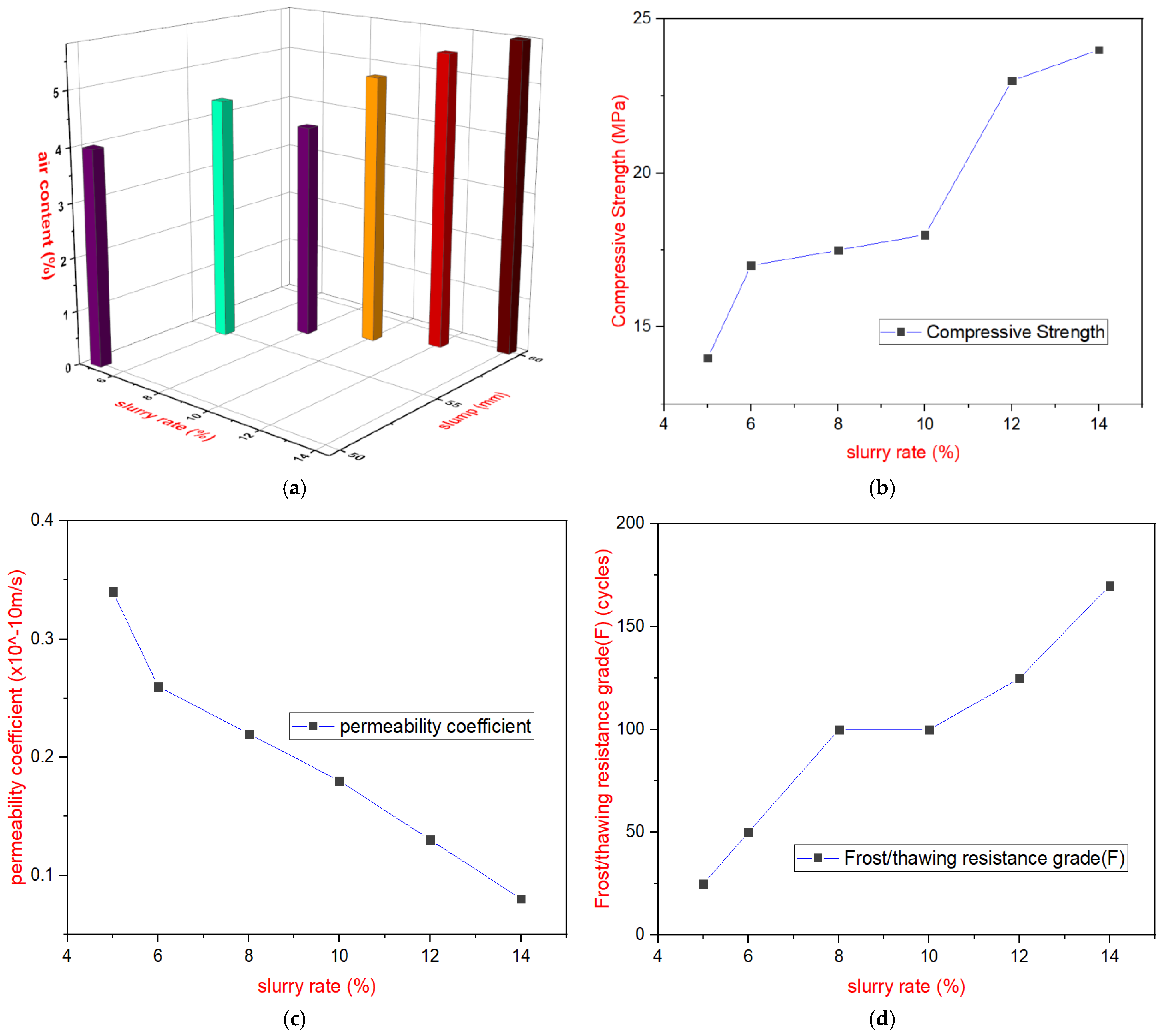
3.1.3. Phase 3: Determination of Grout Addition Rate

The slurry material needed optimal rheological properties to permit optimum penetration into the compacted cemented sand, gravel, and rock (CSGR). This will facilitate adequate compaction to meet the protection and anti-seepage design criteria. While a higher water/cement ratio was found to enhance rheological performance, it also increased the volume of slurry necessary to achieve the design specifications. To address this, Feng et al. [] proposed a method that refines the slurry mix ratio by reducing the water/binder ratio while still ensuring efficient diffusion throughout the mixture and even distribution across the vibrating surface. The optimal slurry mix ratio and characteristics are detailed in Table 11. The rheological performance was regulated through marsh flow time, which was maintained between 26 and 31 s. Additionally, specific gravity, measured with a specific gravity meter, controlled the water/cement ratio during the mixing process [].
Table 11. Slurry mix design and characteristics.
A new formulation of cement slurry in Table 11 (based on experience and design practice) was selected as the grouting material and combined with the Y2 CSGR (C1806) from Table 10 for the slurry rate studies, six different slurry addition rates were tested: 5%, 6%, 8%, 10%, 12%, and 14%. The prepared grout-enriched CSGR mixtures were labeled as GEY2 (GECSGR prepared from the average gradation termed Y2 in Table 7; phase 1). Following the “Test Code for Hydraulic Concrete” (SL/T 352-2020) [], the indoor mixing and forming method for GERCC was applied using a vibrating table. The slurry, according to Table 11, was added to the machine-mixed CSGR, followed by three rounds of manual mixing before specimen formation. Wet sieving was performed to remove particles larger than 40 mm, and the specimens were tested for slump and air content.
The test results are shown in Figure 6 above. Figure 6a reveals that the slump of the mixture after slurry addition ranges from 10 to 60 mm, while the air content ranges between 4% and 5.8%, indicating enhanced workability. Figure 6b also demonstrates that the compressive strength of the GECSGR increases with higher slurry rates. At an 8% slurry addition, with a total cement content of 176 kg/m3, the 90-day compressive strength exceeds 15 MPa for the GECSGR from GEY2, meeting design requirements for the field application (Qianwei dike) with an 80–90% confidence level. The impermeability grade reaches W8 (i.e., permeability coefficient of 0.26 × 10⁻¹⁰ m/s), and the frost resistance grade is F100, as shown in Figure 6c,d, making the material suitable for dams under 30 m in height (i.e., minimum impermeability grade W4 equivalent to permeability coefficient of 0.78 × 10⁻¹⁰ m/s).
Figure 6. Effect of slurry rate on GECSGR performance. (a) Effect of slurry rate, slump, and air content. (b) Effect of slurry rate on compressive strength. (c) Effect of slurry rate on permeability coefficient. (d) Effect of slurry rate on frost/thawing resistance.
At a 12% slurry addition rate, the cementitious content increases to 223 kg/m3, resulting in a 90-day compressive strength exceeding 20 MPa. The impermeability grade improves to W11 (equivalent to a permeability coefficient of 0.16 × 10⁻¹⁰ m/s), and the frost resistance grade rises to F125, fulfilling the design criteria for dams between 30 and 70 m height (minimum impermeability grade W6 or permeability coefficient of 0.42 × 10⁻¹⁰ m/s). However, at a 14% slurry addition rate, the cementitious material reaches 247 kg/m3, significantly raising the costs of GECSGR production due to the large amount of cement and admixture requirement and increasing the risk of crack development. As a result, this higher rate was eliminated [].

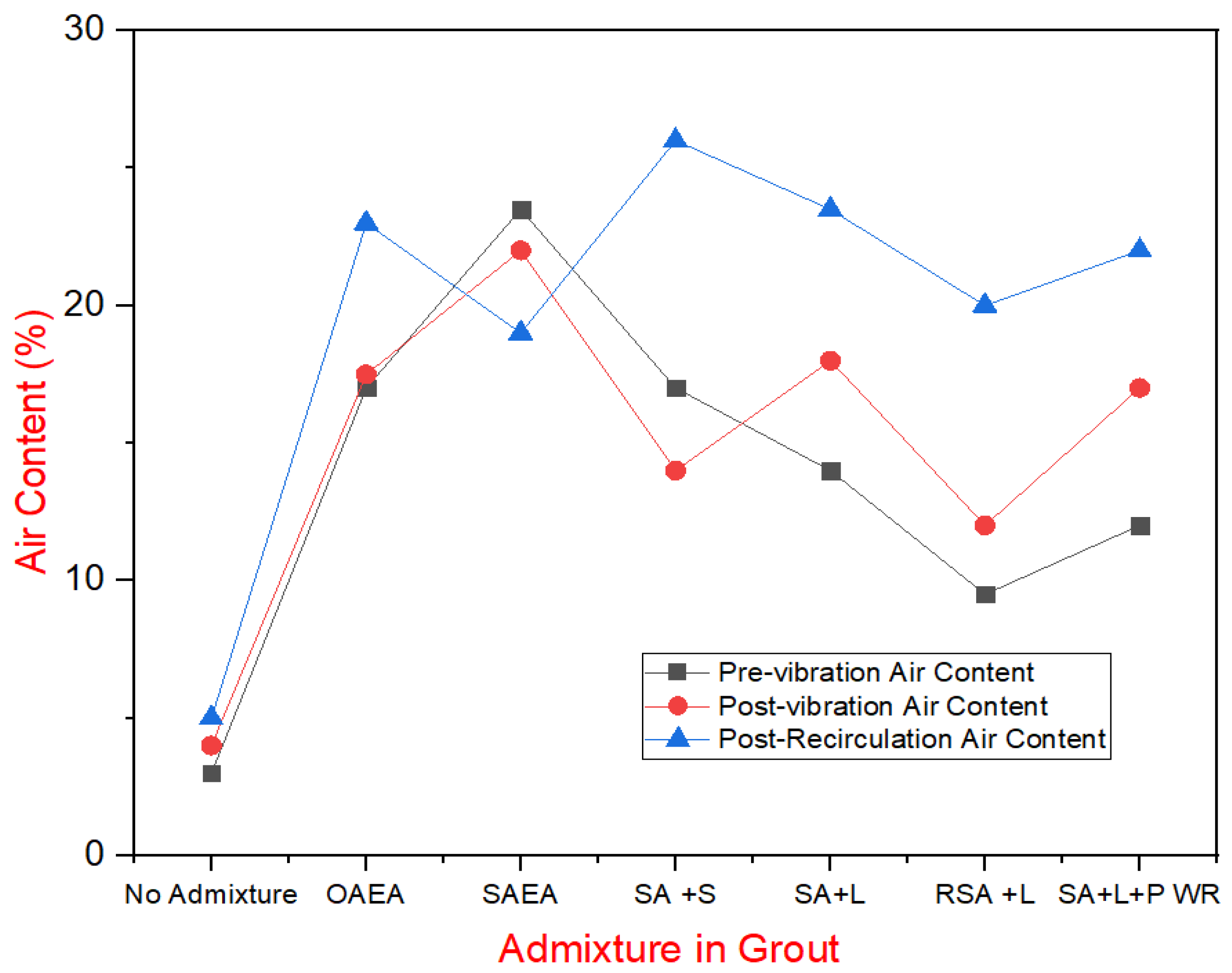
3.1.4. Phase 4: Small-Scale Laboratory GECSGR

During Phase 4, key properties of the grout, CSGR and GECSGR were measured. The flow times for the grout were recorded immediately after mixing and ranged between 26 and 38 s for most mixes. However, the grout containing a water-reducing admixture (WRA) had a significantly longer flow time. This extended flow time is likely due to the thixotropic behavior of the grout when a WRA is added, which increases flow resistance during measurement using the marsh funnel method.
Bleed measurements indicated substantial bleed across the grouts due to their high water-to-cement ratios, with an average of 84 mL. The lowest bleed volume, 39 mL, was observed in the grout with WRA, attributed to its reduced water-to-cement ratio.
Air content was measured at three stages: immediately after mixing, after 30 min of rest followed by one minute of vibration, and after 3 min of recirculation under pressure through the pump. These results are displayed in Figure 7, showcasing the behavior of the grout under varying admixture conditions.
Figure 7. Air content in grout under varying admixture conditions.
Several key observations emerged from the Phase 4 air content data. Notably, the recirculation of grout through the pump did not negatively impact air content; instead, it often increased it. This rise in air content is likely due to the reintroduction of the pumped grout into the holding tank, where it splashed, incorporating more air. Additionally, since the pump drew material from the bottom of the tank, the lighter, more air-entrained grout at the top could have been used for recirculation testing, contributing to the higher air content readings. This also explains why grout samples that rested for 30 min before vibration generally had slightly higher air content.
The synthetic air-entraining agent (AEA) demonstrated superior performance, showing the highest and most consistent initial air contents, which indicates the mixture’s ability to remain homogeneous. This justified the use of synthetic AEA in evaluating other admixtures. Most other admixtures negatively affected the initial air content, with saline having the least impact. One sample, labeled “Reduced Synthetic AEA + Latex”, included a reduced dose of AEA to test if a high air content was necessary for achieving freeze–thaw resistance.
Air content measurements for the GECSGR, shown in Figure 8, corresponded well with expected values based on grout air content and dosage, achieving the target air content of 4–6% required for freeze–thaw resistance. The only exception was the grout with the water-reducing admixture, which had a much higher air content than expected. This could be due to the significantly higher flow time, indicating the grout was less fluid, potentially leading to poor compaction and artificially high air content measurements in the meter, which records all voids, including those from poor compaction.
Figure 8. Air content in GECSGR under varying admixture conditions.
The freeze–thaw test results, as presented in the order of Table 12, Figure 9, and Table 13 and Figure 10, reveal important findings regarding the durability of the tested samples. Table 12 and Figure 9a illustrate the change in modulus of elasticity over the number of freeze–thaw cycles. The only samples to fail the test—defined as a drop in dynamic modulus below 60% of the original—were samples (shown in black) without admixtures. In contrast, all samples containing an air-entraining agent (AEA) retained at least 75% of their initial modulus.
Table 12. Frost and thawing resistance (dynamic modulus of elasticity).
Figure 9. Freeze–thaw resistance of GECSGR. (a) Percentage of initial dynamic modulus of GECSGR. (b) Freeze–thaw samples after 300 cycles.
Table 13. Average values of performance for frost and thawing resistance of GECSGR.
Figure 10. Average performance values of freeze–thaw resistance of GECSGR. (a) Average value of % of initial dynamic modulus of GECSGR. (b) Average value of mass loss of GECSGR after 300 cycles per admixture condition.
Table 13 and Figure 10 summarize the average mass loss and percentage of the original dynamic modulus for each sample set, indicating the threshold values. The highest freeze–thaw resistance was observed in the synthetic AEA sample with the saline water-repelling admixture, which retained 97.9% of its initial modulus, which correlates well with Musselman et al. (2016) results of 96.8% on GERCC under similar conditions []. The remaining mixtures performed similarly well, all meeting satisfactory criteria for freeze–thaw resistance. Figure 9b visually compares the durability of samples with synthetic AEA and saline water-repelling admixtures against the corresponding plain CSGR (i.e., CSGR with no admixture) sample after 300 cycles, demonstrating a significant improvement in durability when air-entrained grout is used.

3.2. Discussion

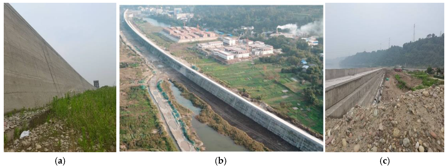
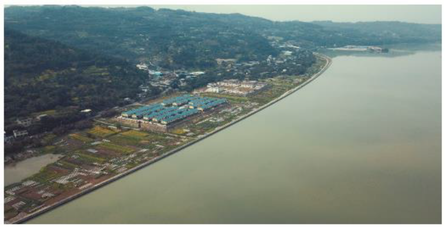
3.2.1. Phase 5: Large-Scale Field Application of GECSGR to Qianwei Dike

Project Requirements for Protect and Seepage Layer and Construction
The Qianwei Dike spans a total length of 2.76 km, featuring a crest elevation of 336.10 m, with a filling volume of 373,000 m3 of CSGR material []. During the design, the protection and seepage control layer made of GECSGR was required for the dam. Therefore, GECSGR of design specification C9015W6F50 was chosen after a series of laboratory and field tests meeting the project requirements (i.e., GECSGR sample of 90-day design compressive strength of 15 MPa, long-term permeability resistance grade of W6, equivalent to 0.24 × 10⁻¹⁰ m/s and could withstand long-term 50 cycles of frost/thawing with average relative dynamic modulus and average mass loss 60% and 5%, respectively).
To create the protection and seepage control layers in both the upstream and downstream regions, GECSGR, with a slurry rate of 9%, was utilized. The construction was executed through sequential rolling and layer-by-layer techniques, resulting in a total of 20,867 m3 of GECSGR used. Figure 11 depicts the construction process of the body, the protection and seepage control layer, and the T-shaped waterstop simultaneously. The T-shaped surface water stop measures a total of 10,163 m and was installed and secured with ease, facilitating rapid construction and simplifying future replacement and repair efforts (see Figure 11b,c). Figure 12 represents the completion of the protection dam before impoundment [].
Figure 11. (a) Construction of the dam body and GECSGR; (b,c) upstream face T-shaped waterstop structure.
Figure 12. The completion of Qianwei Dike: (a) upstream face showing hardened GECSGR; (b) aerial view of the dike and nearby settlement after completing before impoundment; (c) downstream cascaded face of hardened GECSGR.
Quality Test
The quality test results from the construction process are detailed in Table 14. The upstream protection and seepage control layer of the dam adheres to the design specifications of C9015W6F50 [].
Table 14. Quality test results of the GECSGR [].
Performance Test
The first phase of water storage was completed from May 15 to 16, 2020, raising the water level from 326 m to 330 m. Following this, the second phase of water storage was finalized from September 15 to 16, 2021, resulting in an increase in the water level from 330 m to 335 m (see Figure 13). Water storage operations have been ongoing for nearly five (5) years. Importantly, optical fiber leakage measurement devices installed downstream of the transverse joint have shown no signs of leakage, demonstrating the dam’s excellent overall anti-seepage capabilities. Additionally, during the impoundment period, the levee withstood the catastrophic flood in 2020. Despite the severe impact of this disaster on Leshan and Qianwei, the dam effectively managed the flood, protecting the lives and property of over 11,000 residents and more than ten major enterprises in the Tangba Township. Overall, the dam’s safety and reliability have consistently met the expected standards [].
Figure 13. Qianwei Dike under successful full operation with the Tangba community downstream.
Comparison of GECSGR, CVC, and GERCC in CSGRD Applications
GECSGR is created by grouting and vibrating directly onto pre-paved CSGR material. Unlike CVC, it plays a critical role in accommodating transitional deformations at the interface between the impermeable layer and the main body of the dam. This process enhances the continuity and integrity of the dam structure while reducing local damage and delamination caused by sudden changes in material properties. Additionally, GECSGR minimizes the diversity of materials needed at batching plants, thereby improving production efficiency and minimizing construction disruptions. Consequently, it is an ideal choice for future CSGRDs’ protection and seepage control layers as, aside from being a sustainable material, its unit production is also economical compared to CVC and GERCC (shown in Table 15) []. The environmental impacts of the three materials have been compared in Table 16, reinforcing the superiority of the adoption of GECSGR for CSGRD application [].
Table 15. Comparison of the cost of GECSGR, CVC, and GERCC in CSGR application [].
Table 16. Environmental impacts of CVC, GERCC, and GECSGR production.
This study explored the potential for producing air-entrained Grout-Enriched Vibrated CSGR and its application in low dams (dikes or levees). The research has reached a significant milestone; however, additional investigations are needed to thoroughly understand its long-term material performance in engineering applications, particularly for the exclusive use of GECSGR in medium-height dams (30–70 m) and higher dams. The successful implementation of air-entrained vibrated grout-enriched CSGR at the Qianwei Protection Dam provides a valuable case study for similar projects.

4. Conclusions

This paper introduces the successful development and application of air-entrained Grout-Enriched Vibrated CSGR (GECSGR) to the Qianwei protection low dam (dike). The following conclusions are therefore drawn:
  • Grout-enriched vibrated CSGR, if it meets the permeability and frost resistance grade of W12 (permeability coefficient of 0.13 × 10 m/s) and F300 (300 cycles of freeze and thawing with mass loss of <5% or relative dynamic modulus >60% of original), respectively, can be used for the construction of the protection and impermeable layer in CSGRD. These conditions are relaxed based on actual design and project requirements, as seen in the field application.
  • Employing a 223 kg/m3 cement slurry with a water-to-cement ratio of 0.5–0.6, an admixture of 2.23 kg/m3 and grouting rates of 8% and 12%, the C1804 or C1806 dry-hard cemented sand, gravel, and rock characterized by a Vibrating-Compacted (VC) of 25 s can be converted into GECSGR exhibiting a slump range of 10–60 mm, VC 2–8 s, corresponding to grades C9015W8F100 and C9020W11F125, respectively.
  • The organic and synthetic air-entraining admixtures successfully achieved air contents between 13 and 15% and 23–25% when used at their maximum recommended dosages during field applications. However, the synthetic air-entraining agent proved to be the most effective, exhibiting the most stable air content readings and providing superior freeze–thaw resistance when used with appropriate water-resisting admixtures. It can achieve an air content of 4–6%, making it the preferred choice for enhancing durability in GECSGR applications.
  • While the water-reducing admixture effectively reduced bleed and permeability, its inclusion led to significant variability in air content. As a result, the dosage of a water-reducing admixture should be controlled in air-entrained GECSGR for field applications due to its negative impact on maintaining consistent air content.
  • Both water-repelling and efflorescence–controlling admixtures improved the performance of air-entrained grout, with the saline-based admixture demonstrating superior freeze–thaw resistance. However, the powder-based water-resisting admixture negatively affected air entrainment, which required more future research; until then, the dosage should be controlled critically in air-entrained GECSGR.
The ongoing research focuses on optimizing CSGR paste and mortar margins (α and β) and grout mixing techniques, including variations in mud content, sand ratio, different water-reducing agents, and water-repelling powder admixtures. The goal is to establish precise limit criteria for enhancing the performance of CSGR and GECSGR. Also, to gain a comprehensive understanding of its long-term material performance and engineering applications related to CSGRD.

Author Contributions

Formal analysis and Investigation, Y.W. (Yangfeng Wu), B.J. and W.A.B.; Methodology, W.A.B. and C.Z.; Resources, B.J.; Writing—original draft, W.A.B.; Writing—review and editing, W.A.B., J.J. and Y.W. (Yue Wang); Supervision, J.J., C.Z., B.J. and Y.W. (Yue Wang); Funding acquisition, J.J. and B.J. All authors have read and agreed to the published version of the manuscript.

Funding

This research is financially supported by the National Key Research and Development Plan of China under Grant No. 2018 YFC0406801. The State Key Laboratory of Simulation and Regulation of Water Cycles in River Basins also supported this study.

Institutional Review Board Statement

Not applicable.

Data Availability Statement

The original contributions presented in this study are included in the article. Further inquiries can be directed to the corresponding author.

Conflicts of Interest

The authors declare no conflicts of interest.

Abbreviations

The following abbreviations are used in the manuscript:
CSGRCemented Sand, Gravel, and Rock
CSGRDCemented Sand, Gravel, and Rock Dam
CMDCemented Material Dam
C18020Rich-Mix (High Cementitious) CSGR with Compressive Strength of 20 MPa at 180 days
SL678-2014Technical Guideline for Cemented Granular Materials issued by the Ministry of Water Resources of China in 2014
C9015W6F50GECSGR of 15 MPa design Compressive strength after 90 days with permeability resistance grade of W6 (equivalent to 0.42 × 10⁻¹⁰ m/s) and withstand 50 cycles of frost/thawing
C9020W11F125GECSGR of 20 MPa design Compressive strength after 90 days with permeability resistance grade of W11(equivalent to 0.16 × 10⁻¹⁰ m/s) and withstand 125 cycles of frost/thawing
VC Vibrating-Compacted Value
CSGCemented Sand and Gravel
FSHDFaced-Symmetrical Hardfill Dam
RCCRoller Compacted Concrete
MSAMaximum Size of Aggregate
CVCConventional Vibrated Concrete
ICOLDInternational Committee on Large Dams

References

  1. Jia, J.; Lino, M.; Jin, F.; Zheng, C. The Cemented Material Dam: A New, Environmentally Friendly Type of Dam. Engineering 2016, 2, 490–497. [Google Scholar] [CrossRef]
  2. Jia, J.; Wang, S.; Zheng, C.; Chen, Z.; Wang, Y. FOSM-based shear reliability analysis of CSGR dams using strength theory. Comput. Geotech. 2018, 97, 52–61. [Google Scholar] [CrossRef]
  3. Liu, Z.; Jia, J.; Feng, W.; Ma, F.; Zheng, C. Shear Strength of Cemented Sand Gravel and Rock Materials. Sains Malays. 2017, 46, 2101–2108. [Google Scholar] [CrossRef]
  4. Jia, J.; Baah, W.A.; Zheng, C.; Ding, L.; Wu, Y. New stress–strain model and intelligent quality control technology for cemented material dam. J. Intell. Constr. 2024, 2, 9180033. [Google Scholar] [CrossRef]
  5. Wu, Y.; Jia, J.; Zheng, C.; Jia, B.; Wang, Y.; Baah, W.A. A New Method for Constructing the Protection and Seepage Control Layer for CSGR Dam and Its Application. Appl. Sci. 2024, 14, 5423. [Google Scholar] [CrossRef]
  6. Mahmoodi, K.; Noorzad, A.; Mahboubi, A.; Alembagheri, M. Seismic performance assessment of a cemented material dam using incremental dynamic analysis. Structures 2021, 29, 1187–1198. [Google Scholar] [CrossRef]
  7. Yuan, P.; He, Y.; Wang, Y. Study on seismic safety of Poshitougou flood intercepting dam. IOP Conf. Ser. Earth Environ. Sci. 2021, 861, 072073. [Google Scholar] [CrossRef]
  8. Feng, W.; Jia, J.; Liu, Z.; Wang, Y. Study on quantification method for aggregate gradation of discrete Cemented Sand Gravel and Rock. IOP Conf. Ser. Earth Environ. Sci. 2019, 330, 042031. [Google Scholar] [CrossRef]
  9. Jia, J.; Zheng, C.; Li, S.; Ding, L.; Wu, Y. Optimising structural function designing and new practices of cemented material dams in China. Hydropower Dams 2020, 27. [Google Scholar]
  10. Chinese Standard SL678-2014; Technical Guideline for Cemented Granular Material Dams. Chinese National Committee on Large Dams: Beijing, China, 2014.
  11. Chen, J.; Liu, P.; Xu, Q.; Li, J. Seismic analysis of hardfill dams considering spatial variability of material parameters. Eng. Struct. 2020, 211, 110439. [Google Scholar] [CrossRef]
  12. Guo, L.; Zhang, J.; Guo, L.; Wang, J.; Shen, W. Research on profile design criteria of 100 m CSG dams. Case Stud. Constr. Mater. 2022, 16, e01137. [Google Scholar] [CrossRef]
  13. Zhao, X.; He, Y. The Permeable Character of CSG Dams and Their Seepage Fields. Complexity 2018, 2018, 1–14. [Google Scholar] [CrossRef]
  14. Yoshimura, S.; Takasugi, S. Construction of Apporo Trapezoidal CSG Dam. In Innovative Technologies for Dams and Reservoirs toward the Future Generations; Asia-Pacific Group/ICOLD: Tokyo, Japan, 2012; pp. 13–18. [Google Scholar]
  15. Jia, J.; Liu, Z.; Feng, W.; Ma, F.; Zheng, C.; Wang, Y. Water Pressure Induced Corrosion of Cemented Sand, Gravel, and Rock (CSGR). Arab. J. Sci. Eng. 2018, 43, 2083–2092. [Google Scholar] [CrossRef]
  16. Cai, X.; Zhang, Y.; Guo, X.; Zhang, X.; Li, F.; Zhang, T. Review on research progress of cemented sand and gravel dam. Sci. Eng. Compos. Mater. 2022, 29, 438–451. [Google Scholar] [CrossRef]
  17. Ayagh, A.G.; Mohammadian, A. Optimum characteristic compressive strength for cmds (case study: Dasht-e-palang dam). Long-Term Behav. Environ. Friendly Rehabil. Technol. Dams 2017, 243–250. [Google Scholar] [CrossRef]
  18. Cannon, W.R. Air-entrained roller compacted concrete. Concr. Int. 1993, 15, 49–54. [Google Scholar]
  19. Hazaree, C.; Ceylan, H.; Wang, K. Influences of mixture composition on properties and freeze–thaw resistance of RCC. Constr. Build. Mater. 2011, 25, 313–319. [Google Scholar] [CrossRef]
  20. Forbes, B.A. Grout enriched RCC: A History and Future. Int. Water Power Dam Constr. J. 1999, 51, 4. [Google Scholar]
  21. Tatro, S.B.; Hinds, J.K.; West, J.L. Final Report: Properties of Air Entrained Grout Enriched Roller Compacted Concrete. In Proceedings of the United States Society on Dams Annual Conference, Portland, OR, USA, 29 June 2008; pp. 197–211. [Google Scholar]
  22. McDonald, J.E. Grout Enriched Roller-Compacted Concrete—Phase I Investigation; High-Performance Materials and Systems Research Program, US Army Corps of Engineers, Research and Development Center: Vicksburg, MS, USA, 2002. [Google Scholar]
  23. Fitzgerald, T.; Basinger, D.; Cannon, R.; Rogers, G. Grout Enriched RCC at Deep Creek. Int. Water Power Dam Constr. Mag. 2013, 65, 30–33. [Google Scholar]
  24. Musselman, E.; Flynn, R.; Zimmer, G.; Young, J. Optimization of Air Entrained Grout Enriched Roller Compacted Concrete for Improving Freeze-Thaw Resistance of Hydraulic Structures. In Hydraulic Structures and Water System Management, Proceedings of the 6th IAHR International Symposium on Hydraulic Structures, Portland, OR, USA, 27–30 June 2016; Crookston, B., Tullis, B., Eds.; Utah State University: Logan, UT, USA, 2016; pp. 536–545. ISBN 978-1-884575-75-4. [Google Scholar] [CrossRef]
  25. Chinese Standards GB 175-2020; General Purpose Portland Cement GB 175. China Water & Power Press: Beijing, China, 2020. (In Chinese)
  26. AASTM C150/C150M-20; Standard Specification for Portland Cement. ASTM: West Conshohocken, PA, USA, 2022. [CrossRef]
  27. ASTM C618; Standard Specification for Coal Fly Ash and Raw or Calcined Natural Pozzolan for Use in Concrete. ASTM: West Conshohocken, PA, USA, 2019. [CrossRef]
  28. Chinese Standards GB/T1596-2017; Fly Ash Used for Cement and Concrete GB/T1596. China Water & Power Press: Beijing, China, 2020. (In Chinese)
  29. ASTM C403/C403M; Standard Test Method for Time of Setting of Concrete Mixtures by Penetration Resistance. ASTM International: West Conshohocken, PA, USA, 2016.
  30. ASTM C39/C39M; Standard Test Method for Compressive Strength of Cylindrical Concrete Specimens. ASTM International: West Conshohocken, PA, USA, 2021.
  31. ASTM D6910/D6910M; Standard Test Method for Marsh Funnel Viscosity of Construction Slurries. ASTM International: West Conshohocken, PA, USA, 2019.
  32. ASTM C231/C231M; Standard Test Method for Air Content of Freshly Mixed Concrete by the Pressure Method. ASTM International: West Conshohocken, PA, USA, 2022.
  33. ACI 211.1; Standard Practice for Selecting Proportions for Normal, Heavyweight, and Mass Concrete (ACI 211.1-22). American Concrete Institute: Detroit, MI, USA, 2022.
  34. ASTM C1435/C1435M; Standard Practice for Molding Roller-Compacted Concrete in Cylinder Molds Using a Vibrating Hammer. ASTM International: West Conshohocken, PA, USA, 2020.
  35. ASTM C1741; Standard Test Method for Bleed Stability of Cementitious Post-Tensioning Tendon Grout. ASTM International: West Conshohocken, PA, USA, 2018.
  36. ASTM C666; Standard Test Method for Resistance of Concrete to Rapid Freezing and Thawing. ASTM International: West Conshohocken, PA, USA, 2017.
  37. Feng, W.; Jia, J.; Ma, F. Study on durability of dam materials and new-type protective materials for cemented sand and gravel dam. Shuili Xuebao 2013, 44, 500–504. (In Chinese) [Google Scholar]
  38. Chinese Standards SL/T 352-2020; Test Code for Hydraulic Concrete SL/T 352. China Water & Power Press: Beijing, China, 2020. (In Chinese)
Disclaimer/Publisher’s Note: The statements, opinions and data contained in all publications are solely those of the individual author(s) and contributor(s) and not of MDPI and/or the editor(s). MDPI and/or the editor(s) disclaim responsibility for any injury to people or property resulting from any ideas, methods, instructions or products referred to in the content.

Article Metrics

Citations

Article Access Statistics

Multiple requests from the same IP address are counted as one view.