
Additive Manufacturing Post-Processing Treatments, a Review with Emphasis on Mechanical Characteristics

 ,
,  ,
,  , , and
Abstract
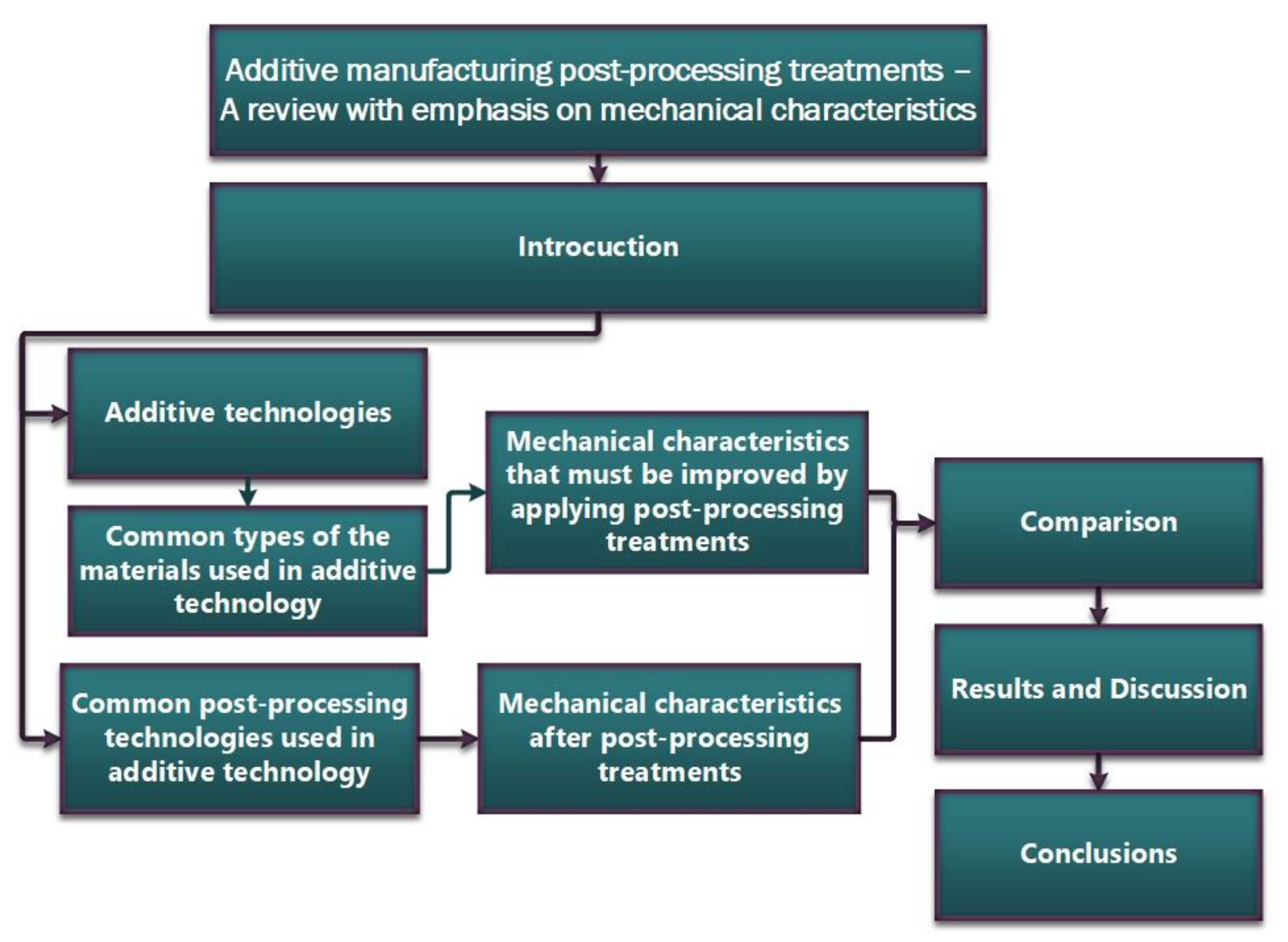
1. Introduction
- Healthcare
- Aerospace
- Manufacturing
- Architecture and construction
- Education
- PLA (Polylactic Acid)
- ABS (Acrylonitrile Butadiene Styrene)
- PETG (Glycol-Modified Polyethylene Terephthalate)
- UV resin
- Flexible resin
- Castable resin
- Titanium
- Stainless steel
- Aluminum
- Inconel
- Cobalt Chromium
- Copper
- Gold
- Nickel
- Bronze
- Silver
- Surface finish
- Strength and durability
- Accuracy
- Costs
- Heat treatment temperature
- Duration of heat treatment
- Atmosphere in the heat treatment furnace
- Cooling rate
- Equipment (furnace for heat treatment)
- Post-processing operations
- Improved mechanical properties of additive parts, including hardness and strength. Additive parts can have internal stresses and micro-cracks that can affect their strength and durability. Heat treatments can reduce these stresses and harden the material, improving part strength and durability;
- Elimination of internal stresses. The 3D printing process can create internal stresses in parts, and heat treatments can help eliminate these stresses, reducing the risk of parts breaking or cracking. The process can also reduce thermal distortion and shrinkage that occurs during the manufacturing process, improving the dimensional stability of parts;
- Improved geometric accuracy. Heat treatment can help reduce non-uniform deformation and shrinkage during the production process, which can improve the geometric accuracy of parts;
- Uniformity/homogeneity of part structure. The 3D printing process can produce parts with a porous structure, and heat treatments can help strengthen the structure by eliminating porosity and voids, thus increasing the homogeneity of the materials used in 3D printing, which can lead to better quality printed parts;
- Impurity removal. The 3D printing process can introduce impurities into the material used, and heat treatments can help remove these impurities;
- Improved adhesion between layers. Heat treatments can increase adhesion between layers of material, which can lead to better stability and strength of printed parts;
- Reduced brittleness. Some materials used in 3D printing can be brittle, and heat treatments can help reduce brittleness by improving hardness and strength;
- Improved ductility. Heat treatments can increase the ductility of some materials, resulting in a better ability to deform under stress;
- Increased corrosion resistance. Parts produced by additive technology can be more susceptible to corrosion than parts produced by other methods. Heat treatments can increase the corrosion resistance of materials, which can extend the life of printed parts;
- Improved surface finish. Heat treatments can also provide the appropriate surface roughness required for certain technical applications, improving the quality and appearance of parts;
- Improved ductility. Parts produced by additive technology can be more brittle than parts produced by other methods. Heat treatments can improve the ductility of the material, making it less susceptible to cracking or fracture;
- Increased thermal and electrical conductivity. Parts produced by additive technology may have lower thermal and/or electrical conductivity than parts produced by other methods. Heat treatments can increase the thermal and/or electrical conductivity of parts, improving their ability to transfer heat;
- Part distortion. If inappropriate temperature regimes are used, they can lead to deformation of additive manufactured parts;
- Undesirable changes in mechanical properties. Additive technology is a manufacturing process that involves the variation of many specific factors that give parts certain mechanical properties. Heat treatments can affect these properties, often in unexpected ways, which can lead to reduced performance;
- Increased porosity. Post-treatment heat treatments can lead to increased porosity in additive manufactured parts, which can adversely affect both the strength and durability of the parts;
- Irregularities on part surfaces. Heat treatments applied to parts produced by additive technology can cause irregularities on the surface of the parts, which can affect their accuracy and quality;
- Increased production time. The length of heat-treatment cycles often involves additional heating, holding, and cooling time, which can significantly increase the production time of parts;
- Higher production costs. Due to the high consumption of equipment/tools, energy, consumables, and labor, heat treatment involves additional costs that can significantly increase the production cost of parts;
- Creation of critical situations in the production process. Heat treatments can be difficult to apply during the part production process, which can lead to complications and delays;
- Increased risk of damage. Both high temperatures and sudden temperature changes can cause damage to parts during heat treatment, resulting in rejection;
- Dimensional limitations. Due to the volume of the furnaces, part dimensions can be limited to small values, which can restrict design and manufacturing options;
- Inherent risks of failure in service. If not carried out correctly, heat treatments can cause parts to fail in service, which can be dangerous in critical applications;
2. Studied Additive Technologies
2.1. Laser Powder Bed Fusion (L-PBF)
- Homogenization, microstructural refinement, and martensite-to-austenite reversion [9];
- Parts distortion [6];
- Heterogeneous microstructure [10];
- Coarse plate martensite with uneven distribution [11];
- Anisotropic microstructures [12];
- Low material density [13];
- Stress-induced cracks and residual porosity [19];
- Intermetallic precipitates [20];
- Internal defects, such as entrapped-gas-pores or lack-of-fusion [21];
- High nitrogen content [22];
2.2. Material Extrusion (ME)
- Need for controllable crystallinity and deterioration phenomenon of polymer materials [28];
- Improving composite flexural properties [36];
- Increasing fracture toughness [51];
- Reducing anisotropy [54];
- Behavior study of annealed defect parts [55];
- Eliminating the warpage of semi-crystalline polymer [56];
- Increasing the dynamic flexural properties [57];
- Poor interfacial bond formation [58].
2.3. Laser Engineered Net Shaping (LENS)
2.4. Directed Energy Deposition (DED)
2.5. Direct Metal Laser Sintering (DMLS)
- ○
- Laser Scanning: In L-PBF, a laser scans the entire surface of the powder bed, melting and fusing the particles together to create a solid part. In contrast, DL-PBF uses a multi-fiber laser head with multiple beams to selectively melt and fuse the powder particles. This allows for greater control over the heat input and leads to a more uniform temperature distribution;
- ○
- Precision: Due to the use of multiple lasers in DL-PBF, the process is generally more precise than L-PBF. This is especially true for parts with fine features or high aspect ratios;
- ○
- Build Time: DL-PBF typically has a faster build time than L-PBF, as the multiple lasers can cover more surface area at once;
- ○
- Materials: L-PBF is generally more versatile in terms of the range of materials that can be processed, including some ceramics and plastics. DL-PBF, on the other hand, is primarily used for metal alloys;
- ○
- Cost: DL-PBF systems tend to be more expensive than L-PBF systems due to the use of multiple lasers and the associated equipment required to control them.
2.6. Metal Binder Jetting (MJB)
2.7. Wire-Arc Additive Manufacturing (WAAM)
3. Used 3D Printing Materials
3.1. Materials Studied and Their Specific Mechanical Behavior with Emphasis on Areas to Improve by Applying Post-Processing Treatments
- PLA (polylactic acid)
- ABS (acrylonitrile-butadiene-styrene)
- PETG (polyethylene terephthalate glycol)
- Nylon (polyamide)
- PEEK (polyether ether ketone)
- TPE (thermoplastic elastomer)
- TPU (thermoplastic polyurethane)
- PVA (polyvinyl alcohol) support material
- PC (polycarbonate)
- PEI (polyetherimide)
- PPS (polyphenylsulfone)
3.2. General Characteristics of Polymers Materials Used in Additive Technologies
3.2.1. Polylactic Acid (PLA)
3.2.2. Acrylonitrile-Butadiene-Styrene (ABS)
3.2.3. Nylon (Polyamide)
3.2.4. Polyethylene terephthalate glycol (PETG)
3.2.5. Thermoplastic Elastomer (TPE)
3.2.6. Thermoplastic Polyurethane (TPU)
3.2.7. Polyvinyl Alcohol (PVA) Support Material
3.2.8. Polycarbonate (PC)
3.2.9. Polyetherimide (PEI)
3.2.10. Polyphenylsulfone (PPS)
3.3. General Characteristics of Metal Materials Used in Additive Technologies
3.4. General Characteristics of Composite Materials Used in Additive Technologies
4. Common Post-Processing Technologies Used in Additive Technology
5. The Influence of Post-Processing Treatments on the Mechanical Properties of 3D Printed Parts
6. Conclusions
Author Contributions
Funding
Institutional Review Board Statement
Informed Consent Statement
Data Availability Statement
Conflicts of Interest
Abbreviations
| AM | Additive Manufacturing |
| RM | Rapid Manufacturing |
| CAD | Computer-Aided Design |
| SS | Stainless Steel |
| FCG | Fatigue Crack Growth |
| PH | Precipitation Hardening |
| PLA | Polylactic Acid |
| PHB | Poly(3-HydroxyButyrate) |
| EVA | Ethylene Vinyl Acetate |
| ABS | Acrylonitrile Butadiene Styrene |
| ME | Material extrusion |
| ASA | Acrilonitril Stiren Acrilat |
| PEEK | Poly-Ether-Ether-Ketone |
| CNF | Cellulose Nanofibers |
| ME | Material extrusion |
| HEAs | High Entropy Alloys |
| HIP | Hot Isostatic Pressing |
| DED | Direct Energy Deposition |
| LDED | Laser Direct Energy Deposition |
| SMAs | Shape Memory Alloys |
| EB-DED | Electron Beam Directed Energy Deposition |
| L-PBF | Laser beam bed fusion |
| SEBM | Selective Electron Beam Melting |
| PETG | PolyEthylene Terephthalate Glycol |
| CFPETG | Carbon Fibers PETG reinforced |
| KFPETG | Kevlar Fibers (Aramid Fibers) PETG reinforced |
| MJF | Multi Jet Fusion |
| HEA | High Entropy Alloy |
| C-HEA | Carbon-High Entropy Alloy |
| LENSTM | Laser Engineered Net Shaping |
| L-PBF | Laser Powder Bed Fusion |
| LDW | Laser Deposition Welding |
| CLAM | China Low Activation Martensitic steel |
| SHT | Standard Heat Treatment |
| DMLS | Direct Metal Laser Sintering |
| PPS | PolyPhenylene Sulfide |
| PA 6 | Polyamide 6 (Nylon 6) |
| PEEK151 | Poly Ether Ketone |
| PAEK | Poly Acryl Ether Ketone |
| LAT | Low Annealing Temperature |
| HAT | High Annealing Temperature |
| WAAM | Wire-Arc Additive Manufacturing |
| CASE® | Chemical Assisted Surface Enhancement |
| SP | Shot Peening |
| LP | Laser Peening |
| HTSN | High Temperature Solution Nitriding |
| PEP | Plasma Electrolytic Polishing |
| EP | Electrochemical Polishing |
| BJP | Binder Jet Printed |
| DLC | Diamond-Like Carbon |
| DA | Direct Aging |
| SR | Stress Relief |
| CCNFs | Carbonized Cellulose Nanofibers |
| PEI | PolyEtherImide |
References
- Zhang, W.; Chabok, A.; Kooi, B.J.; Pei, Y. Additive Manufactured High Entropy Alloys: A Review of the Microstructure and Properties. Mater. Des. 2022, 220, 110875. [Google Scholar] [CrossRef]
- Lin, D.; Xu, L.; Jing, H.; Han, Y.; Zhao, L.; Zhang, Y.; Li, H. A Strong, Ductile, High-Entropy FeCoCrNi Alloy with Fine Grains Fabricated via Additive Manufacturing and a Single Cold Deformation and Annealing Cycle. Addit. Manuf. 2020, 36, 101591. [Google Scholar] [CrossRef]
- Song, B.; Dong, S.; Liu, Q.; Liao, H.; Coddet, C. Vacuum Heat Treatment of Iron Parts Produced by Selective Laser Melting: Microstructure, Residual Stress and Tensile Behavior. Mater. Des. 2014, 54, 727–733. [Google Scholar] [CrossRef]
- Aviles, D.A. Metals An Investigation of the Microstructure and Fatigue Behavior of Additively Manufactured AISI 316L Stainless Steel with Regard to the Influence of Heat Treatment. Metals 2018, 8, 220. [Google Scholar]
- Zhai, Y.; Huang, B.; Mao, X.; Zheng, M. Effect of Hot Isostatic Pressing on Microstructure and Mechanical Properties of CLAM Steel Produced by Selective Laser Melting. J. Nucl. Mater. 2019, 515, 111–121. [Google Scholar] [CrossRef]
- Salman, O.O.; Gammer, C.; Chaubey, A.K.; Eckert, J.; Scudino, S. Effect of Heat Treatment on Microstructure and Mechanical Properties of 316L Steel Synthesized by Selective Laser Melting. Mater. Sci. Eng. A 2019, 748, 205–212. [Google Scholar] [CrossRef]
- Liverani, E.; Lutey, A.; Ascari, A.; Fortunato, A. The Effects of Hot Isostatic Pressing (HIP) and Solubilization Heat Treatment on the Density, Mechanical Properties, and Microstructure of Austenitic Stainless Steel Parts Produced by Selective Laser Melting (SLM). Int. J. Adv. Manuf. Technol. 2020, 107, 109–122. [Google Scholar] [CrossRef]
- Hu, Y.; Chen, H.; Jia, X.; Liang, X.; Lei, J. Heat Treatment of Titanium Manufactured by Selective Laser Melting: Microstructure and Tensile Properties. J. Mater. Res. Technol. 2022, 18, 245–254. [Google Scholar] [CrossRef]
- Conde, F.F.; Escobar, J.D.; Oliveira, J.P.; Béreš, M.; Jardini, A.L.; Bose, W.W.; Avila, J.A. Effect of Thermal Cycling and Aging Stages on the Microstructure and Bending Strength of a Selective Laser Melted 300-Grade Maraging Steel. Mater. Sci. Eng. A 2019, 758, 192–201. [Google Scholar] [CrossRef]
- Zhu, Z.; Li, W.; Nguyen, Q.B.; An, X.; Lu, W.; Li, Z.; Ng, F.L.; Ling Nai, S.M.; Wei, J. Enhanced Strength–Ductility Synergy and Transformation-Induced Plasticity of the Selective Laser Melting Fabricated 304L Stainless Steel. Addit. Manuf. 2020, 35, 101300. [Google Scholar] [CrossRef]
- Tan, C.; Zhou, K.; Ma, W.; Zhang, P.; Liu, M.; Kuang, T. Microstructural Evolution, Nanoprecipitation Behavior and Mechanical Properties of Selective Laser Melted High-Performance Grade 300 Maraging Steel. Mater. Des. 2017, 134, 23–34. [Google Scholar] [CrossRef]
- Bormann, T.; Müller, B.; Schinhammer, M.; Kessler, A.; Thalmann, P.; de Wild, M. Microstructure of Selective Laser Melted Nickel–Titanium. Mater. Charact. 2014, 94, 189–202. [Google Scholar] [CrossRef]
- Haberland, C.; Elahinia, M.; Walker, J.; Meier, H.; Frenzel, J. On the Development of High Quality NiTi Shape Memory and Pseudoelastic Parts by Additive Manufacturing. Smart Mater. Struct. 2014, 23, 104002. [Google Scholar] [CrossRef]
- Mutua, J.; Nakata, S.; Onda, T.; Chen, Z.-C. Optimization of Selective Laser Melting Parameters and Influence of Post Heat Treatment on Microstructure and Mechanical Properties of Maraging Steel. Mater. Des. 2018, 139, 486–497. [Google Scholar] [CrossRef]
- Bodziak, S.; Al-Rubaie, K.S.; Valentina, L.D.; Lafratta, F.H.; Santos, E.C.; Zanatta, A.M.; Chen, Y. Precipitation in 300 Grade Maraging Steel Built by Selective Laser Melting: Aging at 510 °C for 2 h. Mater. Charact. 2019, 151, 73–83. [Google Scholar] [CrossRef]
- Saedi, S.; Saghaian, S.E.; Jahadakbar, A.; Shayesteh Moghaddam, N.; Taheri Andani, M.; Saghaian, S.M.; Lu, Y.C.; Elahinia, M.; Karaca, H.E. Shape Memory Response of Porous NiTi Shape Memory Alloys Fabricated by Selective Laser Melting. J. Mater. Sci. Mater. Med. 2018, 29, 40. [Google Scholar] [CrossRef] [PubMed]
- Saedi, S.; Turabi, A.S.; Andani, M.T.; Moghaddam, N.S.; Elahinia, M.; Karaca, H.E. Texture, Aging, and Superelasticity of Selective Laser Melting Fabricated Ni-Rich NiTi Alloys. Mater. Sci. Eng. A 2017, 686, 1–10. [Google Scholar] [CrossRef]
- The Influence of Heat Treatment on the Thermomechanical Response of Ni-Rich NiTi Alloys Manufactured by Selective Laser Melting-ScienceDirect. Available online: https://www.sciencedirect.com/science/article/pii/S0925838816307459 (accessed on 30 March 2023).
- Li, S.; Hassanin, H.; Attallah, M.M.; Adkins, N.J.E.; Essa, K. The Development of TiNi-Based Negative Poisson’s Ratio Structure Using Selective Laser Melting. Acta Mater. 2016, 105, 75–83. [Google Scholar] [CrossRef]
- Yin, S.; Chen, C.; Yan, X.; Feng, X.; Jenkins, R.; O’Reilly, P.; Liu, M.; Li, H.; Lupoi, R. The Influence of Aging Temperature and Aging Time on the Mechanical and Tribological Properties of Selective Laser Melted Maraging 18Ni-300 Steel. Addit. Manuf. 2018, 22, 592–600. [Google Scholar] [CrossRef]
- Effect of HIP Post-Processing at 850 °C/200 MPa in the Fatigue Behavior of Ti-6Al-4V Alloy Fabricated by Selective Laser Melting. Available online: https://www.x-mol.net/paper/article/1541103637099290624 (accessed on 2 April 2023).
- Funch, C.V.; Somlo, K.; Christiansen, T.L.; Somers, M.A.J. Thermochemical Post-Processing of Additively Manufactured Austenitic Stainless Steel. Surf. Coat. Technol. 2022, 441, 128495. [Google Scholar] [CrossRef]
- Pei, C.; Shi, D.; Yuan, H.; Li, H. Assessment of Mechanical Properties and Fatigue Performance of a Selective Laser Melted Nickel-Base Superalloy Inconel 718. Mater. Sci. Eng. A 2019, 759, 278–287. [Google Scholar] [CrossRef]
- Bean, G.E.; McLouth, T.D.; Witkin, D.B.; Sitzman, S.D.; Adams, P.M.; Zaldivar, R.J. Build Orientation Effects on Texture and Mechanical Properties of Selective Laser Melting Inconel 718. J. Mater. Eng. Perform. 2019, 28, 1942–1949. [Google Scholar] [CrossRef]
- Butt, J.; Bhaskar, R. Investigating the Effects of Annealing on the Mechanical Properties of FFF-Printed Thermoplastics. JMMP 2020, 4, 38. [Google Scholar] [CrossRef]
- Nassar, A.; Younis, M.; Elzareef, M.; Nassar, E. Effects of Heat-Treatment on Tensile Behavior and Dimension Stability of 3D Printed Carbon Fiber Reinforced Composites. Polymers 2021, 13, 4305. [Google Scholar] [CrossRef]
- Influence of Thermal Annealing Temperatures on Powder Mould Effectiveness to Avoid Deformations in ABS and PLA 3D-Printed Parts-PubMed. Available online: https://pubmed.ncbi.nlm.nih.gov/35808650/ (accessed on 30 March 2023).
- Yang, C.; Tian, X.; Li, D.; Cao, Y.; Zhao, F.; Shi, C. Influence of Thermal Processing Conditions in 3D Printing on the Crystallinity and Mechanical Properties of PEEK Material. J. Mater. Process. Technol. 2017, 248, 1–7. [Google Scholar] [CrossRef]
- Slavković, V.; Grujović, N.; Disic, A.; Radovanović, A. Influence of Annealing and Printing Directions on Mechanical Properties of PLA Shape Memory Polymer Produced by Fused Deposition Modeling. In Proceedings of the 6th International Congress of Serbian Society of Mechanics Mountain Tara, Mountain Tara, Serbia, 19–21 June 2017. [Google Scholar]
- Arjun, P.; Bidhun, V.K.; Lenin, U.K.; Amritha, V.P.; Pazhamannil, R.V.; Govindan, P. Effects of Process Parameters and Annealing on the Tensile Strength of 3D Printed Carbon Fiber Reinforced Polylactic Acid. Mater. Today Proc. 2022, 62, 7379–7384. [Google Scholar] [CrossRef]
- Yadav, P.; Angajala, D.K.; Singhal, I.; Sahai, A.; Sharma, R.S. Evaluating Mechanical Strength of Three Dimensional Printed PLA Parts by Free Form Fabrication. Mater. Today Proc. 2021, 46, 9498–9502. [Google Scholar] [CrossRef]
- Szust, A.; Adamski, G. Using Thermal Annealing and Salt Remelting to Increase Tensile Properties of 3D FDM Prints. Eng. Fail. Anal. 2022, 132, 105932. [Google Scholar] [CrossRef]
- Rane, R.; Kulkarni, A.; Prajapati, H.; Taylor, R.; Jain, A.; Chen, V. Post-Process Effects of Isothermal Annealing and Initially Applied Static Uniaxial Loading on the Ultimate Tensile Strength of Fused Filament Fabrication Parts. Materials 2020, 13, 352. [Google Scholar] [CrossRef] [PubMed]
- Zhang, Y.; Roch, A. Fused Filament Fabrication and Sintering of 17-4PH Stainless Steel. Manuf. Lett. 2022, 33, 29–32. [Google Scholar] [CrossRef]
- The Effect of Annealing on Additive Manufactured ULTEMTM 9085 Mechanical Properties-PMC. Available online: https://www.ncbi.nlm.nih.gov/pmc/articles/PMC8199117/ (accessed on 30 March 2023).
- Dong, J.; Mei, C.; Han, J.; Lee, S.; Wu, Q. 3D Printed Poly(Lactic Acid) Composites with Grafted Cellulose Nanofibers: Effect of Nanofiber and Post-Fabrication Annealing Treatment on Composite Flexural Properties. Addit. Manuf. 2019, 28, 621–628. [Google Scholar] [CrossRef]
- Valvez, S.; Silva, A.P.; Reis, P.N.B.; Berto, F. Annealing Effect on Mechanical Properties of 3D Printed Composites. Procedia Struct. Integr. 2022, 37, 738–745. [Google Scholar] [CrossRef]
- Augmenting Effect of Infill Density and Annealing on Mechanical Properties of PETG and CFPETG Composites Fabricated by FDM-ScienceDirect. Available online: https://www.sciencedirect.com/science/article/pii/S2214785320376458 (accessed on 30 March 2023).
- Bhandari, S.; Lopez-Anido, R.A.; Gardner, D.J. Enhancing the Interlayer Tensile Strength of 3D Printed Short Carbon Fiber Reinforced PETG and PLA Composites via Annealing. Addit. Manuf. 2019, 30, 100922. [Google Scholar] [CrossRef]
- de Bruijn, A.C.; Gómez-Gras, G.; Pérez, M.A. Thermal Annealing as a Post-Process for Additively Manufactured Ultem 9085 Parts. Procedia Comput. Sci. 2022, 200, 1308–1317. [Google Scholar] [CrossRef]
- Papon, E.A.; Haque, A.; Spear, S.K. Effects of Functionalization and Annealing in Enhancing the Interfacial Bonding and Mechanical Properties of 3D Printed Fiber-Reinforced Composites. Mater. Today Commun. 2020, 25, 101365. [Google Scholar] [CrossRef]
- Prajapati, H.; Chalise, D.; Ravoori, D.; Taylor, R.M.; Jain, A. Improvement in Build-Direction Thermal Conductivity in Extrusion-Based Polymer Additive Manufacturing through Thermal Annealing. Addit. Manuf. 2019, 26, 242–249. [Google Scholar] [CrossRef]
- Ferreira, I.; Melo, C.; Neto, R.; Machado, M.; Alves, J.; Mould, S. Study of the Annealing Influence on the Mechanical Performance of PA12 and PA12 Fibre Reinforced FFF Printed Specimens. Rapid Prototyp. J. 2020, 20, 1761–1770. [Google Scholar] [CrossRef]
- Wang, S.; Daelemans, L.; Fiorio, R.; Gou, M.; D’hooge, D.R.; De Clerck, K.; Cardon, L. Improving Mechanical Properties for Extrusion-Based Additive Manufacturing of Poly(Lactic Acid) by Annealing and Blending with Poly(3-Hydroxybutyrate). Polymers 2019, 11, 1529. [Google Scholar] [CrossRef]
- Wach, R.A.; Wolszczak, P.; Adamus-Wlodarczyk, A. Enhancement of Mechanical Properties of FDM-PLA Parts via Thermal Annealing. Macromol. Mater. Eng. 2018, 303, 1800169. [Google Scholar] [CrossRef]
- Kishore, V.; Chen, X.; Hassen, A.A.; Lindahl, J.; Kunc, V.; Duty, C. Post-Process Annealing of Large-Scale 3D Printed Polyphenylene Sulfide Composites. Addit. Manuf. 2020, 35, 101387. [Google Scholar] [CrossRef]
- Yi, N.; Davies, R.; Chaplin, A.; McCutchion, P.; Ghita, O. Slow and Fast Crystallising Poly Aryl Ether Ketones (PAEKs) in 3D Printing: Crystallisation Kinetics, Morphology, and Mechanical Properties. Addit. Manuf. 2021, 39, 101843. [Google Scholar] [CrossRef]
- Ivey, M.; Melenka, G.; Carey, J.; Ayranci, C. Characterizing Short-Fiber-Reinforced Composites Produced Using Additive Manufacturing. Adv. Manuf. Polym. Compos. Sci. 2016, 3, 81–91. [Google Scholar] [CrossRef]
- Dong, J.; Huang, X.; Muley, P.; Wu, T.; Barekati-Goudarzi, M.; Tang, Z.; Li, M.; Lee, S.; Boldor, D.; Wu, Q. Carbonized Cellulose Nanofibers as Dielectric Heat Sources for Microwave Annealing 3D Printed PLA Composite. Compos. Part B Eng. 2020, 184, 107640. [Google Scholar] [CrossRef]
- An Experimental Study of Nozzle Temperature and Heat Treatment (Annealing) Effects on Mechanical Properties of High-Temperature Polylactic Acid in Fused Deposition Modeling-Akhoundi-2020-Polymer Engineering & Science-Wiley Online Library. Available online: https://4spepublications.onlinelibrary.wiley.com/doi/full/10.1002/pen.25353 (accessed on 30 March 2023).
- Hart, K.R.; Dunn, R.M.; Sietins, J.M.; Hofmeister Mock, C.M.; Mackay, M.E.; Wetzel, E.D. Increased Fracture Toughness of Additively Manufactured Amorphous Thermoplastics via Thermal Annealing. Polymer 2018, 144, 192–204. [Google Scholar] [CrossRef]
- Kumar Jain, P.A.; Sattar, S.; Mulqueen, D.; Pedrazzoli, D.; Kravchenko, S.G.; Kravchenko, O.G. Role of Annealing and Isostatic Compaction on Mechanical Properties of 3D Printed Short Glass Fiber Nylon Composites. Addit. Manuf. 2022, 51, 102599. [Google Scholar] [CrossRef]
- van de Werken, N.; Koirala, P.; Ghorbani, J.; Doyle, D.; Tehrani, M. Investigating the Hot Isostatic Pressing of an Additively Manufactured Continuous Carbon Fiber Reinforced PEEK Composite. Addit. Manuf. 2021, 37, 101634. [Google Scholar] [CrossRef]
- Park, S.J.; Park, S.J.; Son, Y.; Ahn, I.H. Reducing Anisotropy of a Part Fabricated by Material Extrusion via Warm Isostatic Pressure (WIP) Process. Addit. Manuf. 2022, 55, 102841. [Google Scholar] [CrossRef]
- Khosravani, M.; Božić, Ž.; Zolfagharian, A.; Reinicke, T. Failure Analysis of 3D-Printed PLA Components: Impact of Manufacturing Defects and Thermal Ageing. Eng. Fail. Anal. 2022, 136, 106214. [Google Scholar] [CrossRef]
- Geng, P.; Zhao, j.; Wu, W.; Wang, Y.; Wang, B.; Wang, S.; Li, G. Effect of Thermal Processing and Heat Treatment Condition on 3D Printing PPS Properties. Polymers 2018, 10, 875. [Google Scholar] [CrossRef]
- Chikkanna, N.; Krishnapillai, S.; Ramachandran, V. Static and Dynamic Flexural Behaviour of Printed Polylactic Acid with Thermal Annealing: Parametric Optimisation and Empirical Modelling. Int. J. Adv. Manuf. Technol. 2022, 119, 1179–1197. [Google Scholar] [CrossRef]
- Rheology, Crystallinity, and Mechanical Investigation of Interlayer Adhesion Strength by Thermal Annealing of Polyetherimide (PEI/ULTEM 1010) Parts Produced by 3D Printing|SpringerLink. Available online: https://link.springer.com/article/10.1007/s11665-022-07049-z (accessed on 30 March 2023).
- Marattukalam, J.J.; Balla, V.K.; Das, M.; Bontha, S.; Kalpathy, S.K. Effect of Heat Treatment on Microstructure, Corrosion, and Shape Memory Characteristics of Laser Deposited NiTi Alloy. J. Alloy. Compd. 2018, 744, 337–346. [Google Scholar] [CrossRef]
- Available online: https://www.Manufacturingguide.Com/En/Laser-Engineered-Net-Shaping-Lens-0 (accessed on 13 March 2023).
- Carrozza, A.; Aversa, A.; Mazzucato, F.; Bassini, E.; Manfredi, D.; Biamino, S.; Valente, A.; Fino, P. An Investigation on the Effect of Different Multi-Step Heat Treatments on the Microstructure, Texture and Mechanical Properties of the DED-Produced Ti-6Al-4V Alloy. Mater. Charact. 2022, 189, 111958. [Google Scholar] [CrossRef]
- Zhang, G.; Li, N.; Gao, J.; Xiong, H.; Yu, H.; Yuan, H. Wire-Fed Electron Beam Directed Energy Deposition of Ti–6Al–2Zr–1Mo–1V Alloy and the Effect of Annealing on the Microstructure, Texture, and Anisotropy of Tensile Properties. Addit. Manuf. 2022, 49, 102511. [Google Scholar] [CrossRef]
- Wang, C.; Tan, X.P.; Du, Z.; Chandra, S.; Sun, Z.; Lim, C.W.J.; Tor, S.B.; Lim, C.S.; Wong, C.H. Additive Manufacturing of NiTi Shape Memory Alloys Using Pre-Mixed Powders. J. Mater. Process. Technol. 2019, 271, 152–161. [Google Scholar] [CrossRef]
- AlMangour, B.; Yang, J.-M. Improving the Surface Quality and Mechanical Properties by Shot-Peening of 17-4 Stainless Steel Fabricated by Additive Manufacturing. Mater. Des. 2016, 110, 914–924. [Google Scholar] [CrossRef]
- Tillmann, W.; Lopes Dias, N.F.; Stangier, D.; Schaak, C.; Höges, S. Heat Treatment of Binder Jet Printed 17–4 PH Stainless Steel for Subsequent Deposition of Tribo-Functional Diamond-like Carbon Coatings. Mater. Des. 2022, 213, 110304. [Google Scholar] [CrossRef]
- Ali, M.; Sari, R.; Sajjad, U.; Sultan, M.; Ali, H. Effect of Annealing on Microstructures and Mechanical Properties of PA-12 Lattice Structures Proceeded by Multi Jet Fusion Technology. Addit. Manuf. 2021, 47, 102285. [Google Scholar] [CrossRef]
- Elmer, J.W.; Fisher, K.; Gibbs, G.; Sengthay, J.; Urabe, D. Post-Build Thermomechanical Processing of Wire Arc Additively Manufactured Stainless Steel for Improved Mechanical Properties and Reduction of Crystallographic Texture. Addit. Manuf. 2022, 50, 102573. [Google Scholar] [CrossRef]
- Zhang, Z.; Wang, L.; Zhang, R.; Yin, D.; Zhao, Z.; Bai, P.; Liu, B.; Wang, F. Effect of Solution Annealing on Microstructures and Corrosion Behavior of Wire and Arc Additive Manufactured AZ91 Magnesium Alloy in Sodium Chloride Solution. J. Mater. Res. Technol. 2022, 18, 416–427. [Google Scholar] [CrossRef]
- Arana, M.; Ukar, E.; Rodriguez, I.; Aguilar, D.; Álvarez, P. Influence of Deposition Strategy and Heat Treatment on Mechanical Properties and Microstructure of 2319 Aluminium WAAM Components. Mater. Des. 2022, 221, 110974. [Google Scholar] [CrossRef]
- Zhang, L.; Cao, W.; Zhang, Y.; Jiang, R.; Li, X. Microstructure Evolution and Enhanced Mechanical Properties of Additive Manufacturing Al-Zn-Mg-Li Alloy via Forging and Aging Treatment. J. Mater. Res. Technol. 2022, 18, 4965–4979. [Google Scholar] [CrossRef]
- da Silva Barbosa Ferreira, E.; Luna, C.B.B.; Siqueira, D.D.; Araújo, E.M.; de França, D.C.; Wellen, R.M.R. Annealing Effect on Pla/Eva Blends Performance. J. Polym. Environ. 2022, 30, 541–554. [Google Scholar] [CrossRef]
- Park, J.M.; Kim, E.S.; Kwon, H.; Sathiyamoorthi, P.; Kim, K.T.; Yu, J.-H.; Kim, H.S. Effect of Heat Treatment on Microstructural Heterogeneity and Mechanical Properties of 1%C-CoCrFeMnNi Alloy Fabricated by Selective Laser Melting. Addit. Manuf. 2021, 47, 102283. [Google Scholar] [CrossRef]
- Hamilton, R.F.; Bimber, B.A.; Palmer, T.A. Correlating Microstructure and Superelasticity of Directed Energy Deposition Additive Manufactured Ni-Rich NiTi Alloys. J. Alloys Compd. 2018, 739, 712–722. [Google Scholar] [CrossRef]
- Lin, D.; Xu, L.; Jing, H.; Han, Y.; Zhao, L.; Minami, F. Effects of Annealing on the Structure and Mechanical Properties of FeCoCrNi High-Entropy Alloy Fabricated via Selective Laser Melting. Addit. Manuf. 2020, 32, 101058. [Google Scholar] [CrossRef]
- Zhang, M.; Sun, C.-N.; Zhang, X.; Goh, P.; Wei, J.; Li, H.; Hardacre, D. Elucidating the Relations Between Monotonic and Fatigue Properties of Laser Powder Bed Fusion Stainless Steel 316L. JOM 2017, 70, 390–395. [Google Scholar] [CrossRef]
- Nezhadfar, P.D.; Shrestha, R.; Phan, N.; Shamsaei, N. Fatigue Behavior of Additively Manufactured 17-4 PH Stainless Steel: Synergistic Effects of Surface Roughness and Heat Treatment. Int. J. Fatigue 2019, 124, 188–204. [Google Scholar] [CrossRef]
- Nezhadfar, P.D.; Burford, E.; Anderson-Wedge, K.; Zhang, B.; Shao, S.; Daniewicz, S.R.; Shamsaei, N. Fatigue Crack Growth Behavior of Additively Manufactured 17-4 PH Stainless Steel: Effects of Build Orientation and Microstructure. Int. J. Fatigue 2019, 123, 168–179. [Google Scholar] [CrossRef]
- Cheruvathur, S.; Lass, E.A.; Campbell, C.E. Additive Manufacturing of 17-4 PH Stainless Steel: Post-Processing Heat Treatment to Achieve Uniform Reproducible Microstructure. JOM 2016, 68, 930–942. [Google Scholar] [CrossRef]
- Chmielewska, A.; Wysocki, B.; Kwaśniak, P.; Kruszewski, M.J.; Michalski, B.; Zielińska, A.; Adamczyk-Cieślak, B.; Krawczyńska, A.; Buhagiar, J.; Święszkowski, W. Heat Treatment of NiTi Alloys Fabricated Using Laser Powder Bed Fusion (LPBF) from Elementally Blended Powders. Materials 2022, 15, 3304. [Google Scholar] [CrossRef]
- Simmons, H.; Tiwary, P.; Colwell, J.E.; Kontopoulou, M. Improvements in the Crystallinity and Mechanical Properties of PLA by Nucleation and Annealing. Polym. Degrad. Stab. 2019, 166, 248–257. [Google Scholar] [CrossRef]
- Baran, A.; Polanski, M. Microstructure and Properties of LENS (Laser Engineered Net Shaping) Manufactured Ni-Ti Shape Memory Alloy. J. Alloys Compd. 2018, 750, 863–870. [Google Scholar] [CrossRef]
- Muñoz, J.A.; Elizalde, S.; Komissarov, A.; Cabrera, J.M. Effect of Heat Treatments on the Mechanical and Microstructural Behavior of a Hypoeutectic Al Alloy Obtained by Laser Powder Bed Fusion. Mater. Sci. Eng. A 2022, 857, 144091. [Google Scholar] [CrossRef]
- Salarvand, V.; Sohrabpoor, H.; Mohammadi, M.A.; Nazari, M.; Raghavendra, R.; Mostafaei, A.; Brabazon, D. Microstructure and Corrosion Evaluation of As-Built and Heat-Treated 316L Stainless Steel Manufactured by Laser Powder Bed Fusion. J. Mater. Res. Technol. 2022, 18, 4104–4113. [Google Scholar] [CrossRef]
- Carrozza, A.; Aversa, A.; Fino, P.; Lombardi, M. Towards Customized Heat Treatments and Mechanical Properties in the LPBF-Processed Ti-6Al-2Sn-4Zr-6Mo Alloy. Mater. Des. 2022, 215, 110512. [Google Scholar] [CrossRef]
- Xu, J.; Brodin, H.; Peng, R.L.; Luzin, V.; Moverare, J. Effect of Heat Treatment Temperature on the Microstructural Evolution of CM247LC Superalloy by Laser Powder Bed Fusion. Mater. Charact. 2022, 185, 111742. [Google Scholar] [CrossRef]
- Poulin, J.-R.; Kreitcberg, A.; Brailovski, V. Effect of Hot Isostatic Pressing of Laser Powder Bed Fused Inconel 625 with Purposely Induced Defects on the Residual Porosity and Fatigue Crack Propagation Behavior. Addit. Manuf. 2021, 47, 102324. [Google Scholar] [CrossRef]
- Ardi, D.T.; Guowei, L.; Maharjan, N.; Mutiargo, B.; Leng, S.H.; Srinivasan, R. Effects of Post-Processing Route on Fatigue Performance of Laser Powder Bed Fusion Inconel 718. Addit. Manuf. 2020, 36, 101442. [Google Scholar] [CrossRef]
- du Plessis, A.; Macdonald, E. Hot Isostatic Pressing in Metal Additive Manufacturing: X-Ray Tomography Reveals Details of Pore Closure. Addit. Manuf. 2020, 34, 101191. [Google Scholar] [CrossRef]
- Wang, H.; Chen, L.; Dovgyy, B.; Xu, W.; Sha, A.; Li, X.; Tang, H.; Liu, Y.; Wu, H.; Pham, M.-S. Micro-Cracking, Microstructure and Mechanical Properties of Hastelloy-X Alloy Printed by Laser Powder Bed Fusion: As-Built, Annealed and Hot-Isostatic Pressed. Addit. Manuf. 2021, 39, 101853. [Google Scholar] [CrossRef]
- Grech, I.; Sullivan, J.; Lancaster, R.; Plummer, J.; Lavery, N. The Optimisation of Hot Isostatic Pressing Treatments for Enhanced Mechanical and Corrosion Performance of Stainless Steel 316L Produced by Laser Powder Bed Fusion. Addit. Manuf. 2022, 58, 103072. [Google Scholar] [CrossRef]
- Alagha, A.N.; Hussain, S.; Zaki, W. Additive Manufacturing of Shape Memory Alloys: A Review with Emphasis on Powder Bed Systems. Mater. Des. 2021, 204, 109654. [Google Scholar] [CrossRef]
- Bimber, B.A.; Hamilton, R.F.; Keist, J.; Palmer, T.A. Anisotropic Microstructure and Superelasticity of Additive Manufactured NiTi Alloy Bulk Builds Using Laser Directed Energy Deposition. Mater. Sci. Eng. A 2016, 674, 125–134. [Google Scholar] [CrossRef]
- Elangeswaran, C.; Cutolo, A.; Muralidharan, G.K.; de Formanoir, C.; Berto, F.; Vanmeensel, K.; Van Hooreweder, B. Effect of Post-Treatments on the Fatigue Behaviour of 316L Stainless Steel Manufactured by Laser Powder Bed Fusion. Int. J. Fatigue 2019, 123, 31–39. [Google Scholar] [CrossRef]
- Kamariah, M.S.I.N.; Harun, W.S.W.; Khalil, N.Z.; Ahmad, F.; Ismail, M.H.; Sharif, S. Effect of Heat Treatment on Mechanical Properties and Microstructure of Selective Laser Melting 316L Stainless Steel. IOP Conf. Ser. Mater. Sci. Eng. 2017, 257, 012021. [Google Scholar] [CrossRef]
- Gruber, K.; Szymczyk-Ziółkowska, P.; Dziuba, S.; Duda, S.; Zielonka, P.; Seitl, S.; Lesiuk, G. Fatigue Crack Growth Characterization of Inconel 718 after Additive Manufacturing by Laser Powder Bed Fusion and Heat Treatment. Int. J. Fatigue 2023, 166, 107287. [Google Scholar] [CrossRef]
- Afkhami, S.; Javaheri, V.; Dabiri, E.; Piili, H.; Björk, T. Effects of Manufacturing Parameters, Heat Treatment, and Machining on the Physical and Mechanical Properties of 13Cr10Ni1.7Mo2Al0.4Mn0.4Si Steel Processed by Laser Powder Bed Fusion. Mater. Sci. Eng. A 2021, 832, 142402. [Google Scholar] [CrossRef]
- Navickaitė, K.; Nestler, K.; Böttger-Hiller, F.; Matias, C.; Diskin, A.; Golan, O.; Garkun, A.; Strokin, E.; Biletskiy, R.; Safranchik, D.; et al. Efficient Polishing of Additive Manufactured Titanium Alloys. Procedia CIRP 2022, 108, 346–351. [Google Scholar] [CrossRef]
- Zhang, X.X.; Lutz, A.; Andrä, H.; Lahres, M.; Gong, W.; Harjo, S.; Emmelmann, C. Strain Hardening Behavior of Additively Manufactured and Annealed AlSi3.5Mg2.5 Alloy. J. Alloys Compd. 2022, 898, 162890. [Google Scholar] [CrossRef]
- Pacheco, J.T.; Meura, V.H.; Bloemer, P.R.A.; Veiga, M.T.; de Moura Filho, O.C.; Cunha, A.; Teixeira, M.F. Laser Directed Energy Deposition of AISI 316L Stainless Steel: The Effect of Build Direction on Mechanical Properties in as-Built and Heat-Treated Conditions. Adv. Ind. Manuf. Eng. 2022, 4, 100079. [Google Scholar] [CrossRef]
- Zhang, S.; Zhang, Y.; Qi, J.; Zou, Z.; Qian, Y. Effect of Heat Treatment on the Microstructure and Mechanical Properties of Additive Manufactured Ti-6.5Al-2Zr-1Mo-1V Alloy. Materials 2023, 16, 160. [Google Scholar] [CrossRef] [PubMed]
- Aguado-Montero, S.; Navarro, C.; Vázquez, J.; Lasagni, F.; Slawik, S.; Domínguez, J. Fatigue Behaviour of PBF Additive Manufactured TI6AL4V Alloy after Shot and Laser Peening. Int. J. Fatigue 2022, 154, 106536. [Google Scholar] [CrossRef]
- Zhang, B.; Wei, W.; Shi, W.; Guo, Y.; Wen, S.; Wu, X.; Gao, K.; Rong, L.; Huang, H.; Nie, Z. Effect of Heat Treatment on the Microstructure and Mechanical Properties of Er-Containing Al–7Si–0.6 Mg Alloy by Laser Powder Bed Fusion. J. Mater. Res. Technol. 2022, 18, 3073–3084. [Google Scholar] [CrossRef]


| Category | Examples |
|---|---|
| Polymers | Acrylonitrile Butadiene Styrene (ABS), Polylactic Acid (PLA), Polyethylene Terephthalate Glycol (PETG), Nylon |
| Metals | Stainless Steel, Titanium, Aluminum, Copper |
| Ceramics | Zirconia, Alumina, Silicon Carbide |
| Composites | Carbon Fiber, Glass Fiber, Kevlar |
| Biomaterials | Collagen, Chitosan, Alginate |
| Category | Tensile Strength (MPa) | Elastic Modulus (GPa) | Density (g/cm³) | Typical Uses | Ref. |
|---|---|---|---|---|---|
| Polymers Polymers are the most commonly used 3D printing materials due to their low cost and ease of use. However, their mechanical properties can vary greatly depending on the specific material and printing parameters used. Generally, polymers have lower tensile strength and stiffness compared to metals and ceramics, but they can still be used for a wide range of applications, including prototyping, consumer products, and packaging. | 25–70 | 1–5 | 0.9–1.4 | Consumer products, toys, prototyping, packaging | [38,42,43,52,71] |
| Metals Metal 3D printing is a rapidly growing field due to the high strength and durability of metal parts. However, metal 3D printing is generally more expensive and complex than polymer printing. Metal parts can be printed with a range of tensile strengths, from around 400 MPa for aluminum to over 1200 MPa for titanium. Metal parts also tend to have higher elastic moduli and densities compared to polymers. | 400–1200 | 100–200 | 6–19 | Aerospace, medical implants, automotive parts | [2,4,5,6,7,8,9,10,11,12,13,14] |
| Ceramics Ceramic 3D printing is used for applications that require high temperature resistance, chemical resistance, and wear resistance. Ceramic parts can have tensile strengths ranging from 100 to 400 MPa, and elastic moduli ranging from 100 to 400 GPa. Ceramic parts also tend to have low densities, which makes them useful for aerospace and other weight-sensitive applications. | 100–400 | 100–400 | 2.5–7.5 | Dental implants, aerospace, high-temperature parts | [16,27] |
| Composites Composite materials are made by combining two or more materials to create a new material with enhanced properties. Composites can have tensile strengths ranging from 500 to 2000 MPa, and elastic moduli ranging from 50 to 100 GPa. Composites are used in a wide range of applications, including aerospace, automotive, and sports equipment. | 500–2000 | 50–100 | 1.5–2.5 | Aerospace, automotive, sports equipment | [26,41,49,52,53] |
| Biomaterials Biomaterials are used in 3D printing to create tissue and organ replacements, as well as drug delivery systems. Biomaterials tend to have lower mechanical properties compared to other 3D printing materials, with tensile strengths typically in the range of 1–5 MPa, and elastic moduli in the range of 0.01–0.1 GPa. However, biomaterials have unique properties that make them useful for medical applications, such as biocompatibility and bioresorbability. | 1–5 | 0.01–0.1 | 1–1.5 | Tissue engineering, drug delivery | [1] |
| Property | Value |
|---|---|
| Tensile Strength PLA’s tensile strength typically ranges from 25 to 70 MPa. This is lower than some other 3D printing materials such as ABS and nylon, which can have tensile strengths exceeding 100 MPa. However, PLA can be stiffened by increasing its density through annealing or other post-processing techniques. | 25–70 MPa |
| Young’s Modulus PLA’s Young’s modulus, a measure of its stiffness, typically ranges from 2.7 to 4 GPa. This is higher than some other 3D printing materials such as TPU, but lower than materials such as carbon fiber-reinforced polymers. | 2.7–4 GPa |
| Elongation at Break PLA’s elongation at break, a measure of its ability to stretch before breaking, is typically between 2 and 10%. This is lower than some other materials such as TPU, which can have elongations at break exceeding 500%. | 2–10% |
| Flexural Strength PLA’s flexural strength, a measure of its ability to resist bending, typically ranges from 50 to 100 MPa. This is lower than some other materials such as polycarbonate, which can have flexural strengths exceeding 150 MPa. | 50–100 MPa |
| Density PLA has a density of 1.24–1.27 g/cm3, which is similar to or slightly lower than other common 3D printing materials such as ABS and PETG. | 1.24–1.27 g/cm3 |
| Glass Transition Temp PLA’s glass transition temperature, the temperature at which it transitions from a hard, glassy state to a soft, rubbery state, is typically around 55–60 °C. This can make it unsuitable for use in high-temperature applications. | 55–60 °C |
| Melting Temperature PLA’s melting temperature can vary depending on the specific grade and manufacturer, but is typically between 160 and 220 °C. This relatively low melting temperature, combined with PLA’s low tendency to warp and its ability to produce high-detail prints, makes it a popular material for use in desktop 3D printers. | 160–220 °C (depending on grade) |
| Property | Value |
|---|---|
| Tensile Strength ABS typically has a tensile strength of 40–50 MPa, making it stronger than PLA but weaker than materials such as nylon and polycarbonate. | 40–50 MPa |
| Young’s Modulus ABS has a Young’s modulus of around 2 GPa, making it stiffer than materials such as TPU but less stiff than materials such as polycarbonate. | 2 GPa |
| Elongation at Break ABS typically has an elongation at break of 10–50%, making it more flexible than PLA but less flexible than materials such as TPU. | 10–50% |
| Flexural Strength ABS typically has a flexural strength of 60–100 MPa, making it stronger than PLA but weaker than materials such as polycarbonate. | 60–100 MPa |
| Density ABS has a density of around 1.04–1.05 g/cm3, making it slightly less dense than PLA. | 1.04–1.05 g/cm3 |
| Glass Transition Temperature ABS has a glass transition temperature of around 100 °C, making it more heat-resistant than PLA. | 100 °C |
| Melting Temperature ABS has a melting temperature of around 210–250 °C, making it similar to PLA in terms of print temperature. | 210–250 °C |
| Property | Value |
|---|---|
| Tensile Strength | 90–100 MPa (13,000–15,000 psi) |
| Young’s Modulus | 3.6–4.1 GPa (522,000–594,000 psi) |
| Elongation at Break | 20–50% |
| Flexural Strength | 140–160 MPa (20,000–23,000 psi) |
| Compressive Strength | 120–150 MPa (17,000–22,000 psi) |
| Hardness | 88–90 Shore D |
| High thermal stability: PEEK can withstand continuous exposure to temperatures up to 250 °C (482 °F), with short-term exposure up to 310 °C (590 °F). This makes it suitable for use in high-temperature applications where other materials would break down. | |
| Chemical resistance: PEEK is highly resistant to a wide range of chemicals, including acids, bases, and organic solvents. This makes it ideal for use in harsh environments where exposure to chemicals is a concern. | |
| Biocompatibility: PEEK is biocompatible and has been used in medical implants, such as spinal implants and dental implants. Its biocompatibility makes it an attractive material for medical applications. | |
| Electrical properties: PEEK has excellent electrical insulation properties, making it suitable for use in electrical and electronic applications. | |
| Mechanical Property | Nylon 6 | Nylon 12 |
|---|---|---|
| Tensile strength | 50–80 MPa | 40–50 MPa |
| Nylon has a high tensile strength and high Young’s modulus, which means it can withstand a lot of stress without breaking or deforming. However, it can be prone to warping and shrinking during the printing process, especially if the printer is not well-calibrated or the part design is not optimized for 3D printing. | 7250–11,600 psi | 5800–7250 psi |
| Young’s modulus | 2.5–3.5 GPa | 1.2–2.8 GPa |
| 360,000–507,500 psi | 174,000–406,000 psi | |
| Elongation at break Nylon is also known for its high elongation at break, which means it can stretch quite a bit before breaking. This property can be useful for creating parts that need to flex or bend, such as hinges or springs. | 100–200% | 200–300% |
| Flexural strength | 80–120 MPa | 60–70 MPa |
| In addition to its high tensile strength, nylon also has good flexural and compressive strength. This makes it a good choice for parts that need to support weight or resist deformation under load. | 11,600–17,400 psi | 8700–10,150 psi |
| Compressive strength | 60–80 MPa | 50–70 MPa |
| 8700–11,600 psi | 7250–10,150 psi | |
| Hardness Nylon is a relatively hard material, with a high Shore D hardness rating. This means it can resist scratching and other surface damage but may also make it more difficult to print fine details or intricate shapes. | 80–110 Shore D | 70–80 Shore D |
| Mechanical Property | Value |
|---|---|
| Tensile strength PETG has a relatively high tensile strength for a 3D printing material, making it strong and durable. | 50–70 MPa (7250–10,150 psi) |
| Young’s modulus PETG has a relatively low Young’s modulus compared to some other 3D printing materials, such as PLA or ABS. This means that PETG is more flexible and less brittle, making it less likely to break under stress. | 2.0–3.0 GPa (290,000–435,000 psi) |
| Elongation at break PETG has a relatively high elongation at break, indicating that it can stretch and bend without breaking. | 70–130% |
| Flexural strength PETG has a relatively high flexural strength, making it resistant to bending or flexing. | 80–90 MPa (11,600–13,050 psi) |
| Compressive strength PETG has a relatively high compressive strength, making it able to withstand heavy loads. | 60–80 MPa (8700–11,600 psi) |
| Hardness PETG has a moderate hardness, making it durable and resistant to wear and tear. | 68–72 Shore D |
| Material | Extrusion Temperature (°C) | Speed (mm/s) | Layer Height (mm) | Infill (%) | |
|---|---|---|---|---|---|
| PETG | 265 | 20 | 0.4 | 100 | |
| PETG CF | 195 | 60 | 0.52 | 100 | |
| PETG KV | 265 | 20 | 0.35 | 100 | |
| Samples Group | Temperature (°C) | Time (min) | Samples Group | Temperature (°C) | Time (min) |
| 1 | 90 | 30 | 2 | 90 | 240 |
| 3 | 90 | 480 | 4 | 110 | 30 |
| 5 | 110 | 240 | 6 | 110 | 480 |
| 7 | 130 | 30 | 8 | 130 | 240 |
| 9 | 130 | 480 | |||
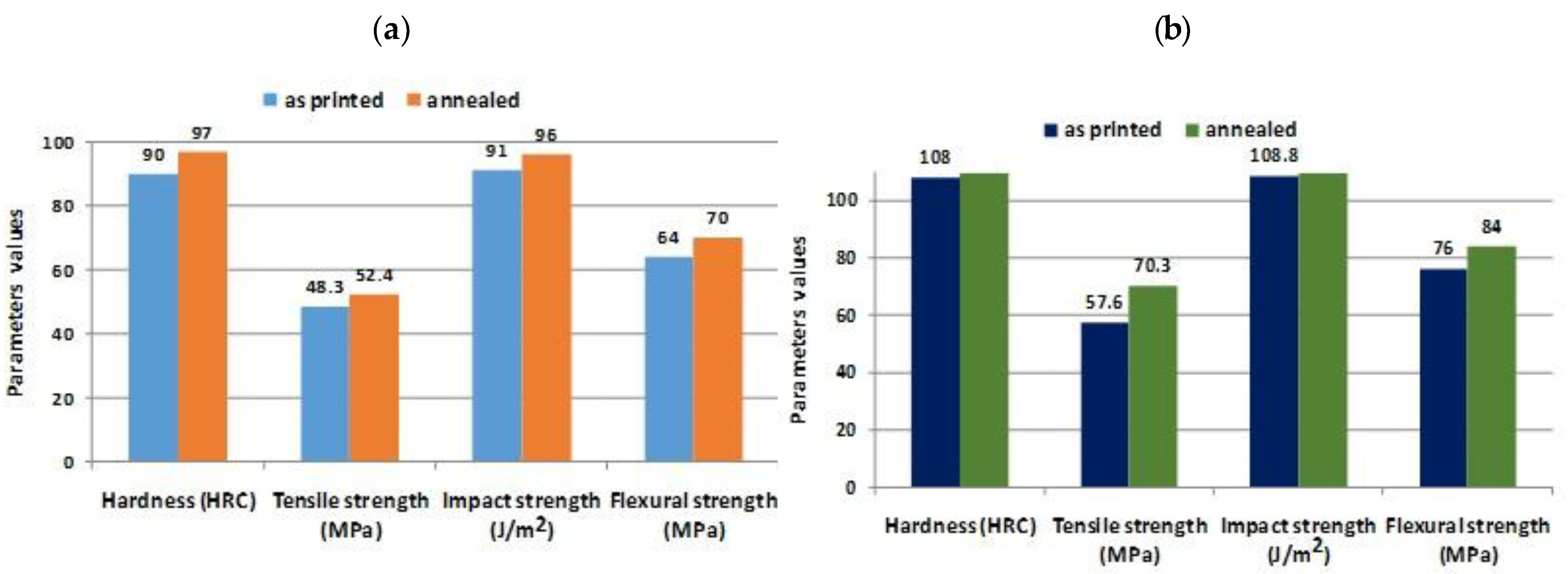
| Material/Post Process | Infill Density | Hardness (HRC) | Tensile Strength (MPa) | Impact Strength (J/m2) | Flexural Strength (MPa) |
|---|---|---|---|---|---|
| Annealed PETG | 25% | 69 | 38 | 68 | 51 |
| 50% | 77 | 41 | 74 | 59 | |
| 75% | 90 | 47 | 88 | 65 | |
| 100% | 97 | 52.4 | 96 | 70 | |
| Annealed CFPETG | 25% | 93 | 53 | 89 | 67 |
| 50% | 106 | 59 | 101 | 71 | |
| 75% | 119 | 64 | 113 | 78 | |
| 100% | 124 | 70.3 | 122 | 84 |
| Parameter | Value | Parameter | Value |
|---|---|---|---|
| Nozzle Diameter | 0.8 mm | Extruder Temperature | 250 °C (PETG and PETG-CF) |
| 210 °C (PLA and PLA-CF) | |||
| Retraction distance | 1.5 mm | Bed Temperature | 90 °C (PETG and PETG-CF) 55 °C (PLA and PLA-CF) |
| Retraction speed | 60 mm/s | Printing speed | 30 mm/s |
| Layer height | 0.36 mm | Printing speed for first layer | 15 mm/s |
| Outline perimeters/shells | 2 | Movement speed | 60 mm/s |
| Top/ bottom solid layers | 0 | Layer cooling fan | Off |
| Infill | None |
| Parameter | Value | Parameter | Value | |
|---|---|---|---|---|
| Speed | 60 mm/s | Layer thickness | 0.2 mm | |
| Bed temperature | 60 °C | 0.3 mm | ||
| Number of shells | 3 | 0.4 mm | ||
| Air gap | 0 | |||
| Infill pattern | Rectilinear | Annealing Temperature | 80 °C | 120 °C |
| Nozzle temperature | 210 °C | Infill density | 60% | 90% |
| Parameter | Value | Parameter | Value |
|---|---|---|---|
| Nozzle diameter (mm) | 0.35 | Layer thickness (mm) | 0.15 |
| Printing bed material | Kapton | Shell thickness (mm) | 1.05 |
| Printing bed temperature, Tbed (°C) | 55 | Infill rate (%) | 100 |
| Nozzle temperature, Nozzle (°C) | 190—PLA with PHB, 210—PLA | Strand orientation (◦) | 45 |
| Printing speed (mm s−1) | 50 | ||
| Materials | Drying Protocol | Annealing Conditions (For Pellets and Part) |
|---|---|---|
| Neat PPS | 120 °C, 3 h (Vacuum) | 250 °C, 18 h, Air 250 °C |
| PPS 40CF | 130 °C, 4 h (Vacuum) | 18 h, Air |
| PPS 50CF | 130 °C, 4 h (Vacuum) | 250 °C, 18 h, Air |
| PPS 60CF | 130 °C, 4 h (Vacuum) | 250 °C, 18 h, Air |
| Post fabrication Treatment | Parameters |
|---|---|
| Annealing (AN) | 150 °C for 4 h 170 °C for 4 h 200 °C for 30 min |
| Annealing with Compaction (AN-C) | 150 °C for 4 h at 0.55 MPa 170 °C for 4 h at 0.55 MPa Step 1: 200 °C for 30 min at 0.55 MPa Step 2: 150 °C for 2 h (without pressure) |
| Material | Tm (°C) | Tg (°C) | Shear Viscosity (Pa.s) | Filament Diameter (mm) |
|---|---|---|---|---|
| Victrex PEEK 151 | 346 | 140 | 130 | 1.75 |
| Victrex AM 200 | 304 | 156 | 250 | 1.75 |
| Material | Printing Bed °C | Printing Nozzle °C | Printing Chamber °C | Build Orientation | Annealing Temperature | Time h | |
|---|---|---|---|---|---|---|---|
| LAT * | HAT ** | ||||||
| Victrex PEEK151 | 100 | 410 | 60 | Flat, Side, Vertical | 156 | 200 | 2, 4 |
| Victrex AM 200 | 100 | 380 | 60 | Flat, Side, Vertical | 170 | 200 | 2, 4 |
| Filament Type | Density g/cc | Tensile Strength (MPa) | Tensile Modulus (MPa) | Tensile Elongation (%) | Flexural Strength (MPa) | Extrusion Temp | Glass Transition Temperature |
|---|---|---|---|---|---|---|---|
| PLACF | 1.29 | 48 | 4950 | 2 | 89 | 215 °C | 60 °C |
| ABSCF | 1.11 | 46 | 5210 | 2 | 76 | 230 °C | 105 °C |
| Property | CF15 | FX256 |
|---|---|---|
| Material density (g/cm3) | 1.08 | 1.01 |
| Melt flow index (g/10 min) | 9.92 | 95 |
| Tensile strength (MPa) | 54.50 | 45.00 |
| Tensile modulus (MPa) | 500 | 1400 |
| Melting temperature (8 °C) | 160 | 178 |
| Print temperature (8 °C) | 235–260 | 235–260 |
| Nozzle Diameter | 0.4 mm |
|---|---|
| Nozzle material | brass/A2 steel |
| Layer height | 0.3 mm |
| Number of perimeters per layer | 2 |
| Infill percentage | 100% |
| Infill pattern | Rectilinear 645 |
| Skirt outlines | 7 |
| Extrusion temperature | 260 °C |
| Bed temperature | 90 °C |
| Bed surface | Tempered glass |
| Printing speeds | 40 mm/s |
| Extrusion multiplier | 1.04 |
| Parameter | Value |
|---|---|
| Density | 1.27 g/cm3 |
| Molecular formula | C37H24O6N2 |
| Glass transition temperature (Tg) | 215 °C |
| Extrusion tip temperature | 400 °C |
| Max. build platform temperature | 190 °C |
| Layer thickness | 330 µm |
| Infill density | 100% |
| Raster angle | 0/90 |
| Materials | Additive Manufacturing Technology | Post- Processing | Investigated Properties |
|---|---|---|---|
| Nickel-based superalloy | L-PBF | Stress-relief heat treatment | Microstructural evolution Elemental segregation Ubiquitous to AM process |
| Ti–6Al–4V TiB/Ti–6Al–4V composite | L-PBF | Annealing heat treatment | Microstructures’ evolution Mechanical properties |
| Inconel 718 | L-PBF | Annealing heat treatment | Dislocation structures Chemical segregation and Precipitates/Laves phase |
| Ti6Al4V | L-PBF | Hot isostatic pressing | Building orientation Mechanical properties Microstructures |
| AlSi10Mg | L-PBF | Solution heat-treated Annealing process | Microstructures Mechanical properties |
| Ti2AlNb | L-PBF | Solution-treated Water quenching Aging-treated | Microstructure Mechanical Properties |
| IN738LC superalloy | L-PBF | Solid-solution artificial aging treatment | Microstructure evolution High temperature oxidation |
| Titanium Alloy | L-PBF | Annealing heat treatment | Microstructural Mechanical Properties |
| AlSi10Mg | L-PBF | Annealing heat treatment | Thermal conductivity Porosity measurement Microstructure |
| AlSi10Mg | L-PBF | Annealing heat treatment | Mechanical properties |
| Low-carbon steel Austenitic-stainless steel | WAAM | Annealing heat treatment Water quenching | Microstructure Mechanical behavior |
| Ti6Al4V | L-PBF | Hot isostatic pressing Annealing heat treatment | Microstructure Mechanical properties |
| Polymer | ME | Temperature change hot chamber | Thermal performance |
| Ti6Al4V | EBM | Super β transus treatment | Compressive strength |
| Ti-6A1–4V | EBM | Vacuum heat treatment | Mechanical properties Microstructure |
| Ti-6Al-4V | LMD | Vacuum solution and aging heat treatment | Fatigue crack growth |
| Element% | Fe | Co | Ni | Cr | Si | C |
|---|---|---|---|---|---|---|
| FeCoCrNi HEA powder | 24.47 | 24.66 | 24.47 | 26.24 | 0.12 | 0.06 |
| HEAs Systems | Additive Technology | Phase Compositions (Detailed HEA Compositions) | |
|---|---|---|---|
| AlCoCrCuFeNi | L-PBF | FCC + BCC (AlCoCrCuFeNi) | |
| LMD | BCC + B2 (Al1.5CoCrCuFeNi) | ||
| FCC + BCC (AlCoCrCuFeNi) | |||
| AlCoCrCuFeNiTi | LMD | BCC + L21 (AlCo0.5CrCu0.5FeNi1.5Ti0.4) | |
| AlCoCrCuFeNi + WC | L-PBF | FCC + WC + W2C + g-carbide (20% AlCoCrCuFeNi + 80% WC) | |
| AlCoCrFeMnNi | L-PBF | FCC (AlCo0.9CrFeMn0.9Ni), FCC + BCC + B2 + Oxides (AlCoCrFeMnNi) | |
| LMD | FCC (Al0.1CoCrFeMnNi), FCC + BCC (Al0.26CoCrFeMnNi, Al0.43CoCrFeMnNi) | ||
| AlCoCrFeMoNiW | L-PBF | FCC + B2 (Al18Co30Cr10Mo1Ni30W1) | |
| AlCoCrFeNi | L-PBF | FCC (Al0.1CoCrFeNi) | |
| FCC (Al0.3CoCrFeNi) | |||
| FCC (Al0.5CoCrFeNi) | |||
| FCC + BCC (Al0.5CoCrFeNi) | |||
| BCC (AlCoCrFeNi) | |||
| BCC + B2 (AlCoCrFeNi) | |||
| A2 + B2 (AlCoCrFeNi) | |||
| BCC + Oxides (AlCoCr1.3FeNi1.3) | |||
| LMD | FCC (Al0.3CoCrFeNi), FCC + BCC (Al0.6CoCrFeNi), BCC (Al0.85CoCrFeNi) | ||
| FCC (Al0.3CoCrFeNi), FCC + BCC + B2 (Al0.6CoCrFeNi), BCC + B2 (Al0.85CoCrFeNi) | |||
| FCC (Al0.2CoCrFeNi), FCC + BCC (Al0.45CoCrFeNi, Al0.7CoCrFeNi), BCC + B2 (AlCoCrFeNi) | |||
| FCC (Al0.3CoCrFeNi1.7), FCC + B2 (Al0.7CoCrFeNi1.3), A2 + B2 + L12 (AlCoCrFeNi), A2 + B2 (Al1.7CoCrFeNi0.3) | |||
| FCC (Al0.3CoCrFeNi), FCC + BCC (Al0.7CoCrFeNi) | |||
| FCC (Al0.3CoCrFeNi) | |||
| FCC + B2 (Al0.3CoCrFeNi) | |||
| FCC + B2 (AlxCoCrFeNi2.1, 0.6 x 1.1) BCC (AlCoCrFeNi) | |||
| BCC + B2 (AlCoCrFeNi) | |||
| BCC + B2 (AlCoxCr1-xFeNi, 0 < x < 1) | |||
| FCC + B2 (AlCoCrFeNi1.2) | |||
| FCC + BCC (AlCoCrFeNi2.1) | |||
| FCC + BCC (AlCo2.2CrFeNi, AlCo2.8CrFeNi) | |||
| FCC + B2 (Al18Co30Cr10Fe10Ni32) | |||
| FCC + L12 (Al7.1Co14.2Cr14.2Fe14.2Ni50), FCC + L12 + BCC (Al12.5Co12.5Cr12.5Fe12.5Ni50, | |||
| Al16.7Co1.1Cr11.1Fe11.1Ni50) | |||
| EBM | FCC + BCC + B2 (AlCoCrFeNi) | ||
| WAAM | FCC + BCC (Al2Co1.8Cr0.3Fe2.7Ni3.2) | ||
| A2 + B2 (Al2.1Co0.3Cr0.5FeNi2.1) | |||
| Al3Ni+(Ni, Co)3Al4 (Al2.1Co0.3Cr0.5FeNi2.1) | |||
| AlNi + CrFe + Al2FeCo (Al36.5Co4.9Cr8.6Fe16.4Ni33.7) | |||
| AlCoCrFeNi/CoCrFeNi laminated structure | LMD | FCC + BCC (AlCoCrFeNi + CoCrFeNi) | |
| AlCoCrFeNiTi | L-PBF | FCC (AlCoCrFeNiTi), FCC + BCC + B2 (AlCo0.8CrFeNiTi) | |
| LMD | FCC + Oxides (Al0.2Co1.5CrFeNi1.5Ti0.3) | ||
| A2 + B2 (AlCoCrFeNiTi0.5) | |||
| FCC + BCC + AlNi3 intermetallic (AlCoCrFeNiTi) | |||
| FCC (Al4(CoCrFeNi)94Ti2) | |||
| (AlCoCrFeNiTi) | |||
| AlCoCrFeNiTi/CoCrFeMnNi laminated structure | LMD | FCC + BCC (AlCoCrFeNiTi0.5 + CoCrFeMnNi) | |
| AlCoCrFeNiV | L-PBF | FCC (Al0.5CoCr0.8FeNi2.5V0.2) | |
| AlCoCuFeNi | L-PBF | BCC (AlCoCuFeNi) | |
| BCC + B2 (AlCoCuFeNi) | |||
| LMD | FCC (Al0.25CoCu0.75FeNi, Al0.5CoCu0.5FeNi), FCC + BCC (Al0.75CoCu0.25FeNi) | ||
| AlCoFeMnNi | L-PBF | FCC (Al0.26CoFeMnNi) | |
| AlCoFeMnNi + C | L-PBF | (Al0.26C0.12CoFeMnNi) | |
| AlCoFeNi AlCoFeNiSmTiV | LMD L-PBF | BCC + B2 (AlCoxCr1-xFeNi, 0 x 1) FCC (AlCoFeNiSm0.1TiV0.9) | |
| AlCoFeNiSmTiVZr | L-PBF | Several intermetallic such as Al-Sm, Al3V, Al3Zr, (Fe, Al)2Zr (AlCoFeNiSm0.05TiV0.95Zr) | |
| AlCoFeNiSmV | L-PBF | FCC (AlCoFeNiSm0.1V0.9) | |
| AlCoFeNiTi | L-PBF | Al7(CoFeNi)86Ti7 | |
| AlCoFeNiTiVZr | L-PBF | FCC (AlCoFeNiTiVZr) | |
| AlCrCuFeNbNi | LMD | FCC + BCC (AlCrCuFeNbxNi, x = 0.05, 0.16, 0.26) | |
| AlCrCuFeNi | L-PBF | BCC + B2 (AlCrCuFeNi) | |
| FCC (Al0.5CrCuFeNi2), FCC + BCC + B2 (Al0.75CrCuFeNi2, Al1.0CrCuFeNi2) | |||
| FCC + BCC + B2 (AlCrCuFeNix, x = 2.0, 2.5, 2.75, 3.0, 3.5) | |||
| LMD | FCC + L12 + BCC + B2 (Al0.8CrCuFeNi2, Al1.0CrCuFeNi2), FCC + BCC + B2 (Al1.3CrCuFeNi2, Al1.5CrCuFeNi2) | ||
| FCC + BCC (AlCrCuFeNi) | |||
| AlCrCuFeNiW | LMD | FCC + BCC (AlCrCuFeNiWx, x = 1% and 3%) | |
| AlCrFeMoV | LMD | BCC (AlCrFeMoVx, 0 < x < 1) | |
| AlCrFeNi | L-PBF | FCC + BCC + B2 (AlCrFe2Ni2) | |
| LMD | BCC + B2 (AlCrFeNi) | ||
| FCC + BCC + B2 (AlCrFe2Ni2) | |||
| lCrFeNiV | L-PBF | FCC + L12 (Al0.5Cr0.9FeNi2.5V0.2) | |
| (Al0.5CrFeNi2.5V0.2) | |||
| AlCrMoNbTa | EBM | BCC (Al0.5CrMoNbTa0.5) | |
| BCC + Cr2Nb intermetallic phases (Al0.5CrMoNbTa0.5) | |||
| CoCrCuFeNi | LMD | (CoCrCu0.5FeNi) | |
| CoCrCuFeMnSi | L-PBF | FCC + HCP (Co20Cr15Cu1.5Fe38.5Mn20Si5) | |
| CoCrFeMn | L-PBF | FCC + HCP (Co10Cr10Fe50Mn30) | |
| LMD | FCC + HCP (Co10Cr10Fe50Mn30) | ||
| CoCrFeMn + C | L-PBF | FCC (Co10Cr10Fe49.5Mn30C0.5) | |
| LMD | FCC (Co10Cr10Fe49.5Mn30C0.5) | ||
| CoCrFeMnNbNi | LMD | ((CoCrFeMnNi)1-xNbx, 0 < x < 0.3) | |
| CoCrFeMnNi | L-PBF | FCC (CoCrFeMnNi) | |
| FCC + r (CoCrFeMnNi) | |||
| FCC + HCP (CoCrFeMnNi) | |||
| FCC + Oxides (CoCrFeMnNi) | |||
| FCC + x (CoCr1.3FeMnNi0.7) | |||
| (CoCrFeMnNi) | |||
| LMD | FCC (CoCrFeMnNi) | ||
| FCC + BCC (CoCrFeMnNi) | |||
| FCC ((CoCrFeMnNi)1-xFex, x = 0.1, 0.2, 0.3, 0.4, 0.5), FCC + BCC ((CoCrFeMnNi)0.4Fe0.6) | |||
| (CoCrFeMnNi) | |||
| EBM | FCC (CoCrFeMnNi) | ||
| CoCrFeMnNi + C | L-PBF | FCC (CoCrFeMnNi + 1% C) | |
| FCC (CoCrFeMnNi + 0.2% C) | |||
| FCC ((CoCrFeMnNi)100-xCx, x = 0.5, 1.0, 1.5) | |||
| CoCrFeMnNi + CeO2 | LMD | FCC + Oxides (CoCrFeMnNi + 1% CeO2) | |
| CoCrFeMnNi + Fe-based metallic glass | L-PBF | FCC + amorphous phase (CoCrFeMnNi + x% (Fe43.7Co7.3Cr14.7Mo12.6C15.5B4.3Y1.9), x = 5, 10, 20, 30) | |
| CoCrFeMnNi + N | L-PBF | FCC (CoCrFeMnNi + 50% N2 mixed with Ar) | |
| CoCrFeMnNi-(N, Si) | L-PBF | FCC + amorphous phase (Co20.26Cr19.43Fe21.69Mn16.83Ni20.45N0.92Si0.42) | |
| CoCrFeMnNiTa | LMD | ((CoCrFeMnNi)1-xTax, 0 < x < 0.9) | |
| CoCrFeMnNiTi | EBM | FCC + CrFe + Cr2Ti + Ni3Ti (CoCrFeMn0.18NiTi), BCC + CrFe + Cr2Ti + Ni3Ti (CoCrFeMn0.5NiTi, CoCrFeMn2NiTi) | |
| CoCrFeMnNi + TiAlV | LMD | ((CoCrFeMnNi)1-x(TiAl6V4)x, 0 < x < 1) | |
| CoCrFeMnNi + TiB2 | LMD | FCC + TiB2 (CoCrFeMnNi + 5% TiB2) | |
| CoCrFeMnNi + TiC | L-PBF | FCC + TiC (CoCrFeMnNi + 1% TiC) | |
| LMD | FCC + TiC (CoCrFeMnNi + x% TiC, x = 2.5, 5) | ||
| CoCrFeMnNi + TiN | L-PBF | FCC + TiN (CoCrFeMnNi + 5% TiN) | |
| FCC + TiN (CoCrFeMnNi + 12% TiN) | |||
| CoCrFeMnNi + WC | LMD | FCC + M23C6 (CoCrFeMnNi + x% WC, x = 5, 10) | |
| CoCrFeMnSi | L-PBF | FCC + HCP (Co20Cr15Fe40Mn20Si5) | |
| FCC + HCP ((Co10Cr10Fe50Mn30)100-xSix, x = 1, 3, 5) | |||
| CoCrFeMoNi | LMD | FCC (CoCrFeMo0.2Ni) | |
| CoCrFeMoNiTi | L-PBF | FCC + HCP (Co1.5CrFeMo0.1Ni1.5Ti0.5) | |
| FCC (Co27Cr16Fe18Mo28Ni8Ti3) | |||
| EBM | FCC + Ni3Ti (Co1.5CrFeMo0.1Ni1.5Ti0.5) | ||
| CoCrFeNbNi | LMD | FCC + Laves (CoCrFeNbxNi, x = 0.1, 0.15, 0.2) | |
| FCC + Laves + Cubic Nb-rich phase (CoCrFe Nb0.2Ni2.1) | |||
| CoCrFeNi | L-PBF | FCC (CoCrFeNi) | |
| FCC (CoCr0.5FeNi) | |||
| FCC + BCC + d (Co23Cr21Fe21Ni35) | |||
| FCC (CoCrFeNi3) | |||
| FCC (Co15Cr10Fe60Ni15) | |||
| (CoCrFeNi) | |||
| LMD | FCC (CoCrFeNi) | ||
| FCC (Cox1Crx2Fex3Nix4, x1 = 7~44, x2 = 5~32, x3 = 5~45, x4 = 19~58) | |||
| CoCrFeNi + Al alloy | LMD | (12 % CoCrFeNi + AA5083 composite) | |
| CoCrFeNi + C | L-PBF | FCC (CoCrFeNiC0.05) | |
| FCC + M23C6 (CoCrFeNiC0.05) | |||
| CoCrFeNi + N | L-PBF | FCC (CoCrFeNi + 1.8% N) | |
| CoCrFeNi + Diamond | L-PBF | FCC + Diamond + Cr7C3 (CoCrFeNi / diamond composite) | |
| CoCrFeNi + Ti-coated diamond | L-PBF | FCC + Diamond (CoCrFeNi / Ti-coated diamond composite) | |
| CoCrFeNiSi | L-PBF | FCC (CoCrFeNiSi0.05) | |
| CoCrFeNiTiW | L-PBF | BCC (CoCr2.5FeNi2TiW0.5) | |
| BCC + TiN (CoCr2.5FeNi2TiW0.5, under N2 protective gas) | |||
| CoCrFeNiW | L-PBF | FCC + W (CoCrFeNiW0.2) | |
| CoFeNiTi | LMD | FCC ((CoFeNi)100-xTix, x = 0, 1, 2, 3, 4) | |
| CrCuFeNi | L-PBF | FCC (CrCuFeNi2) | |
| CrCuFeTiV | LMD | FCC + BCC (CrCuFeTiV) | |
| CrFeMnNi | L-PBF | FCC (CrFeMnNi) | |
| CrFeMoNiTi | LMD | FCC + r + Ni3Ti + Ti nitride ((CrFeNi)90Mo5Ti5), r + C14 Laves + Chi phase + Ni3Ti + TiN ((CrFeNi)80Mo10Ti10), | |
| CrFeNiTiVZr | LMD | FCC + r + C14 Laves + Ni3Ti + TiN ((CrFeNi)80Mo15Ti5) | |
| C14 Laves + aTi-rich phase (CrFeNiTiVZr) | |||
| CrFeNiTiW | L-PBF | FCC (Cr4Fe9Ni5TiW) | |
| FCC + Unknown phase (Cr4Fe9Ni6TiW) | |||
| CuNbNiTiZrFeLaMnNiV | LMD | ((CuNbTiZr)65Ni35) | |
| r + La(Ni,Mn)5 (Fe0.2La0.03Mn0.4Ni0.17V0.2, Fe0.3 La0.03Mn0.2Ni0.17V0.3, Fe0.16La0.06Mn0.33Ni0.28V0.16, Fe0.2La0.07Mn0.2Ni0.33V0.2), FCC + La(Ni,Mn)5 (Fe0.1La0.07Mn0.4Ni0.33V0.1, Fe0.1La0.1Mn0.2Ni0.5V0.1) | |||
| HfNbTaTiZr | LMD | BCC (HfNbTaTiZr) | |
| MoNbNiTa | L-PBF | BCC (MoNbNiTa) | |
| MoNbNiTaTi | L-PBF | BCC (MoNbNi0.5TaTi0.5) | |
| MoNbTaTi | L-PBF | BCC (MoNbTaTi) | |
| MoNbTaTiZr | L-PBF | BCC (Mo0.6Nb0.6Ta0.6Ti1.4Zr1.4) | |
| MoNbTaVW | L-PBF | BCC (MoNbTaVW) | |
| MoNbTaW | L-PBF | BCC (MoNbTaW) | |
| LMD | BCC (MoNbTaW) | ||
| BCC (MoNbTaWx, x = 0, 0.16, 0.33, 0.53) | |||
| BCC (MoNbTaW, (MoNbTa)xW1-x, (MoTaW)xNb1-x, 0 < x < 0.9) | |||
| (MoNbTaW) | |||
| MoNbTaWTi | WAAM | BCC (MoNbTaWTi) | |
| MoNbTiVZr | LMD | BCC + NbTi4-type phase + aZr-rich phase (MoNbTiVZr) | |
| NbTaTiZr | LMD | BCC (NbTaTiZr) | |
| BCC (NbxTa25Ti25Zr50-x, 0 x 50) | |||
| Al | Zr | Mo | V | Si | Fe | N | H | O |
|---|---|---|---|---|---|---|---|---|
| 6.46 | 1.96 | 1.12 | 1.59 | 0.01 | 0.03 | 0.004 | 0.0012 | 0.11 |
| Material | Extrusion Temperature (°C) | Speed (mm/s) | Layer Height (mm) | Infill (%) |
|---|---|---|---|---|
| PETG | 265 | 20 | 0.4 | 100 |
| PETG CF | 195 | 60 | 0.52 | 100 |
| PETG KV | 265 | 20 | 0.35 | 100 |
| Samples Group | Temperature (°C) | Time (min) |
|---|---|---|
| 1 | 90 | 30 |
| 2 | 90 | 240 |
| 3 | 90 | 480 |
| 4 | 110 | 30 |
| 5 | 110 | 240 |
| 6 | 110 | 480 |
| 7 | 130 | 30 |
| 8 | 130 | 240 |
| 9 | 130 | 480 |
| Material/ Postprocess | Infill Density | Hardness (HRC) | Tensile Strength (MPa) | Impact Strength (J/m2) | Flexural Strength (MPa) |
|---|---|---|---|---|---|
| Annealed PETG | 0.25 | 69 | 38 | 68 | 51 |
| 0.5 | 77 | 41 | 74 | 59 | |
| 0.75 | 90 | 47 | 88 | 65 | |
| 1 | 97 | 52.4 | 96 | 70 | |
| Annealed CFPETG | 0.25 | 93 | 53 | 89 | 67 |
| 0.5 | 106 | 59 | 101 | 71 | |
| 0.75 | 119 | 64 | 113 | 78 | |
| 1 | 124 | 70.3 | 122 | 84 |
| Post-Processing Treatments | Authors | Source | Technology | Material | Post-Processing Parameters | Scope |
|---|---|---|---|---|---|---|
| Annealing | Eduardo da Silva Barbosa Ferreira, Carlos Bruno Barreto Luna, Danilo Diniz Siqueira, Edcleide Maria Araújo, Danyelle Campos de França, Renate Maria Ramos Wellen | [71] | ME | PLA and EVA blends | 90 °C, for 5 h in a vacuum oven | Investigation of the effects of EVA blends with PLA and annealing with the aforementioned primers on the increase in crystallinity, modulus of elasticity (tensile strength), resilience to impact bending test, impact strength, HDT, VST, Shore D hardness, and contact angle. |
| Javaid Butt, Raghunath Bhaskar | [25] | ME | ABS, PLA, copper-enhanced PLA and aluminum-enhanced ASA (acrylonitrile styrene acrylate) | 70, 80, 90 °C for 3D FilaPrint PLA 70, 80, 90 °C for FilaPrint metal copper PLA 105, 115, 125 °C for 3D FilaPrint ABS 70, 80, 90, 105, 115 °C for ASA extra fill aluminum | Effects of annealing at different temperatures on the mechanical properties of two commonly used polymeric materials (ABS and PLA) compared with those of two metal-infused thermoplastics (copper-enhanced PLA and aluminum-enhanced ASA). | |
| Vukašin Slavković, Nenad Grujović, Aleksandar Dišić, Andreja Radovanović | [29] | ME | Thermoplastics shape memory material | 75 °C, 2 h, then cooled down to the ambient temperature at a rate not exceeding 6–30 °C/h. | Identification of the mechanical properties of PLA in terms of the influence of the direction of printing and of post-production annealing on the stiffness and on the tensile and compressive strength. | |
| Ju Donga, Changtong Meib, Jingquan Hanb, Sunyoung Leec, Qinglin Wua | [36] | ME | PLA and CNF mixture | 120 °C for 12 h in a vacuum oven, followed by a 24 h period in which the samples are cooled in an oven without heating | Dynamic mechanical analysis, including temperature ramp, frequency sweep, and creep for annealed samples. | |
| Danyang Lin, Lianyong Xu, Hongyang Jing, Yongdian Han, Lei Zhao, Yankun Zhang, Huan Li | [2] | L-PBF process | FeCoCrNi high-entropy alloy | Compressed samples (50% reduction) are annealed at 500, 700, 900, or 1100 °C for 2 h | Influence of the annealing process after cold forming on the recrystallization and the mechanical properties of the alloy. | |
| C. Wanga, X.P. Tana, Z. Dub, S. Chandraa, Z. Suna, C.W.J. Lima, S.B. Tora, C.S. Limc, C.H. Wonga | [63] | DED, L-PBF, SEBM | NiTi Alloys | Solution Heat Treatment (annealing) in a furnace with flowing argon gas at 1000 °C for 6 h, and subsequently quenched in water. | Comparative investigation of the in situ alloy formation of Ni-Ti SMA by DED, L-PBF and SEBM. | |
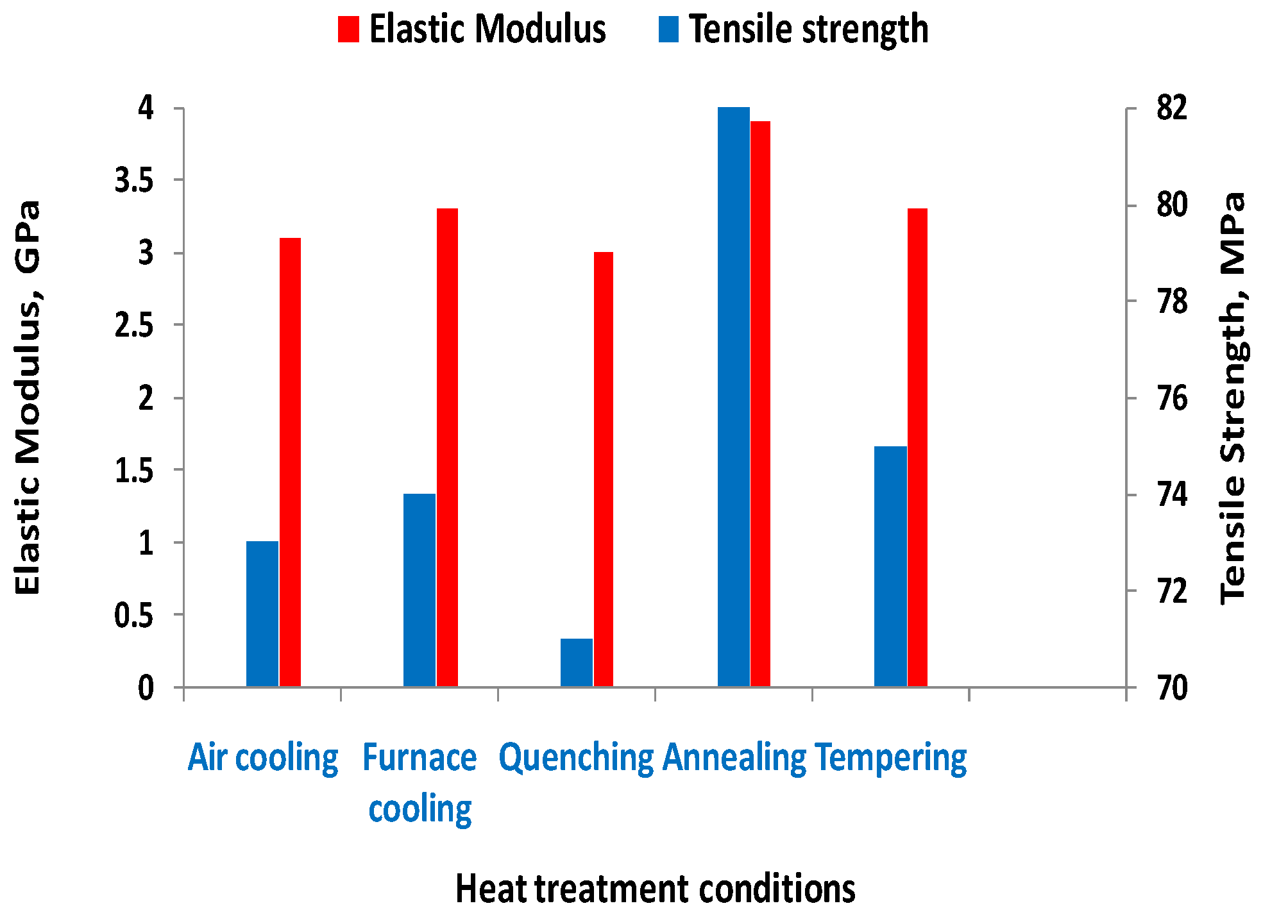
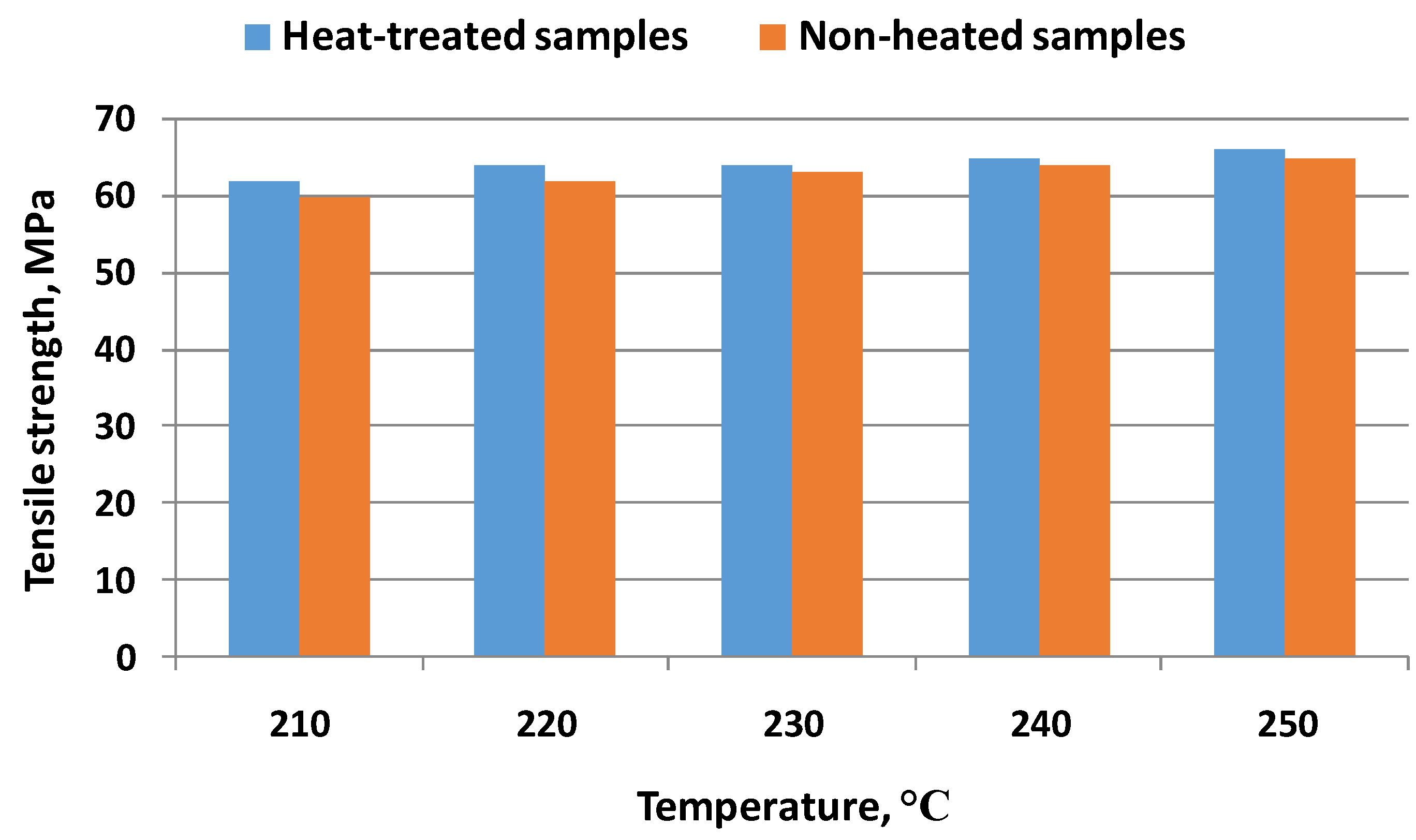
| S. Valvez, A.P. Silva, P.N.B Reis, F. Berto | [37] | ME | PETG, CFPETG, and KFPETG | 90 °C, 110 °C, and 130 °C and 30 min, 240 min, and 480 min annealing times | Evaluate the behavior of specimens in terms of geometric parameters, hardness, and elastic properties. | |
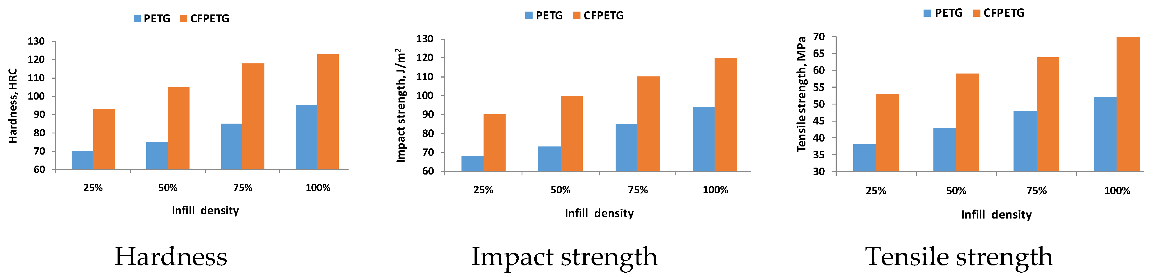
| Beth A. Bimber, Reginald F. Hamilton, Jayme Keist, Todd A. Palmer | [38] | ME | PETG and CFPETG | Heat above 5 °C above the glass transition temperature (95 °C) for 60 min, then cool to room temperature. | Study of the effect of ME packing density on the mechanical properties of PETG- and CFPETG-printed samples with different packing densities, such as 25%, 50%, 75%, and 100%, respectively, and with process parameters kept constant at the optimum value. | |
| Reginald F. Hamilton, Beth A. Bimber, Todd A. Palmer | [73] | LDED | NiTi—SMAs | A solution treatment (annealing) of 950 °C for 24 h followed by aging of the treated material as a solid solution | Deformation analysis at the microstructure scale to investigate the influence of solution and aging heat treatments on the mechanical properties and in particular the superelastic behavior and martensitic transformation morphologies of NiTi alloys produced by additive technology. | |
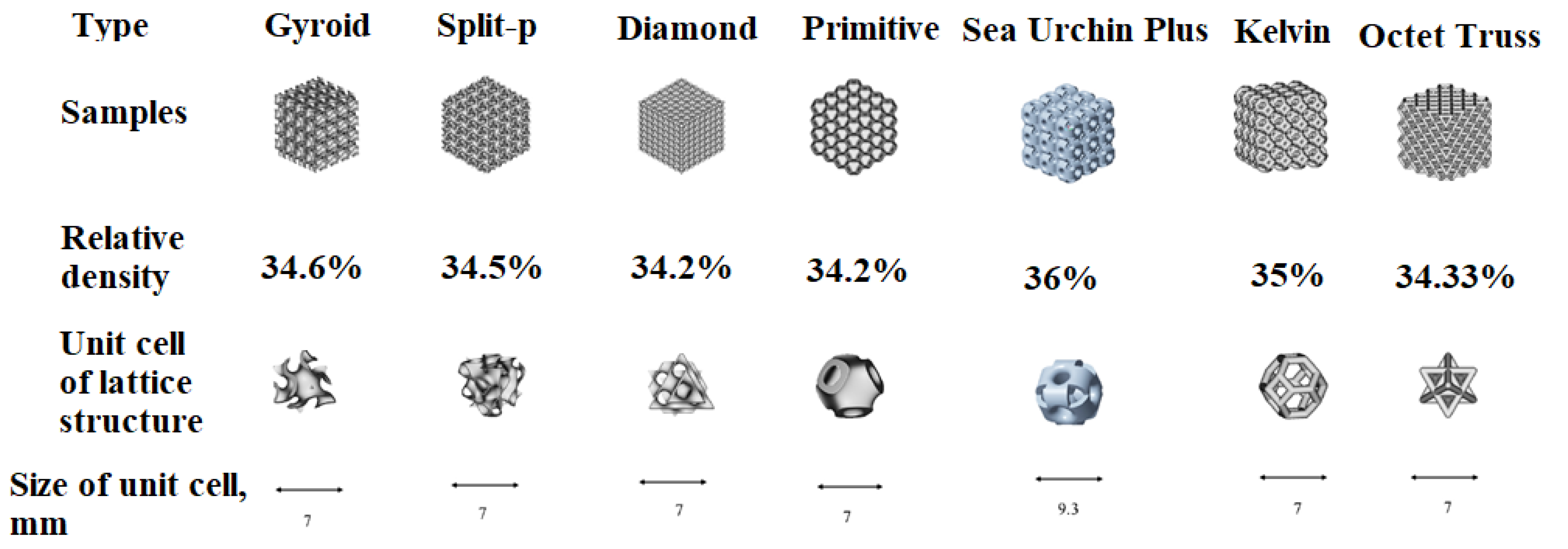
| Mubasher Ali, Resy Kumala Sari, Uzair Sajjad, Muhammad Sultan, Hafiz Muhammad Ali | [66] | MJF | Polyamide Plastic (PA-12) | 110 °C and 130 °C for a constant time period 2 h. | Study of surface roughness and mechanical strength for seven different lattice polymer structures, namely Diamond, Gyroid, Kelvin, Split-P, SUP, Primitive, and Octet. | |
| Jeong Min Park, Eun Seong Kim, Hyeonseok Kwon, Praveen Sathiyamoorthi, Kyung Tae Kim, Ji-Hun Yu, Hyoung Seop Kim | [72] | L-PBF | 1%C-CoCrFeMnNi High-Entropy Alloy (C-HEA) | 800 °C and 900 °C for 10 min, followed by water quenching. | Study of the effect of heat treatment on the evolution of the microstructure and the mechanical properties of a C-HEA material processed by means of L-PBF. | |
| Jithin J. Marattukalam, Vamsi K. Balla, Mitun Dasc, Srikanth Bontha, Sreeram K. Kalpathy | [59] | LENSTM | NiTi Alloy | 30 min at 500 °C and 1000 °C in flowing argon, followed by furnace-cooling to room temperature. | Analysis of the effect of heat treatment on the microstructure, phase transition formation, shape memory properties, and corrosion behavior of laser deposited equiatomic NiTi. | |
| Danyang Lina, Lianyong Xua, Hongyang Jing, Yongdian Han, Lei Zhao, Fumiyoshi Minami | [74] | L-PBF | FeCoCrNi—HEAs | 500–1300 °C for 2 h | Evaluation of the impact of different annealing temperatures in the evolution of dislocation network under and the resulting effects on the mechanical properties. | |
| P. Arjun, V.K. Bidhun, U.K. Lenin, V.P. Amritha, Ribin Varghese Pazhamannil, P. Govindan | [30] | ME | 20% carbon-infused PLA | 65 °C, 95 °C, 125 °C, and 155 °C considering the glass-transition temperature and melting point for a duration of 30, 60, 120, and 240 min | Study on the impact of process variables and thermal annealing on the tensile strength of carbon fiber and polylactic acid composite thermoplastics. | |
| Bastian Blinn, Marcus Klein, Christopher Gläßner, Marek Smaga, Jan C. Aurich, Tilmann Beck | [4] | L-PBF, LDW, Continuous Casted | AISI 316L Stainless Steel | 1070 °C for 2 h and afterwards cooling in H2O | Analysis of the complex relationships between additive manufacturing processes, the resulting microstructure, and the mechanical properties of materials and components. | |
| O.O. Salman, C. Gammerb, A.K. Chaubey, J. Eckertb, S. Scudino | [6] | L-PBF | AISI 316L Stainless Steel | 300 °C, 600 °C, 1000 °C, 1100 °C and 1400 °C for 6 h | Investigation of the influence of annealing at different temperatures on the phase stability, composition, and microstructure of 316L stainless steel produced by L-PBF, in order to understand the corresponding changes in the mechanical properties of specimens under tensile loading. | |
| Meng Zhang, Chen-Nan Sun, Xiang Zhang, Phoi Chin Goh, Jun Wei, Hua Li, David Hardacre | [75] | L-PBF | Stainless Steel 316L. | Heat treatment in accordance with AMS2750 at two different holding temperatures, i.e., 982 °C and 1093 °C, for 25 min followed by gas quenching to prevent carbide precipitation. | Examination of the monotonic and fatigue properties of L-PBF stainless steels in the as-rolled and heat-treated condition 316L. | |
| Zhiguang Zhu, Weilin Li, Quy Bau Nguyen, Xianghai An, Wenjun Lu, Zhiming Li, Fern Lan Ng, Sharon Mui Ling Nai, Jun Wei | [10] | L-PBF | 304L Stainless Steel | - | Systematic study of the microstructure, mechanical behavior and deformation mechanisms of L-PBF-processed 304L stainless steel. | |
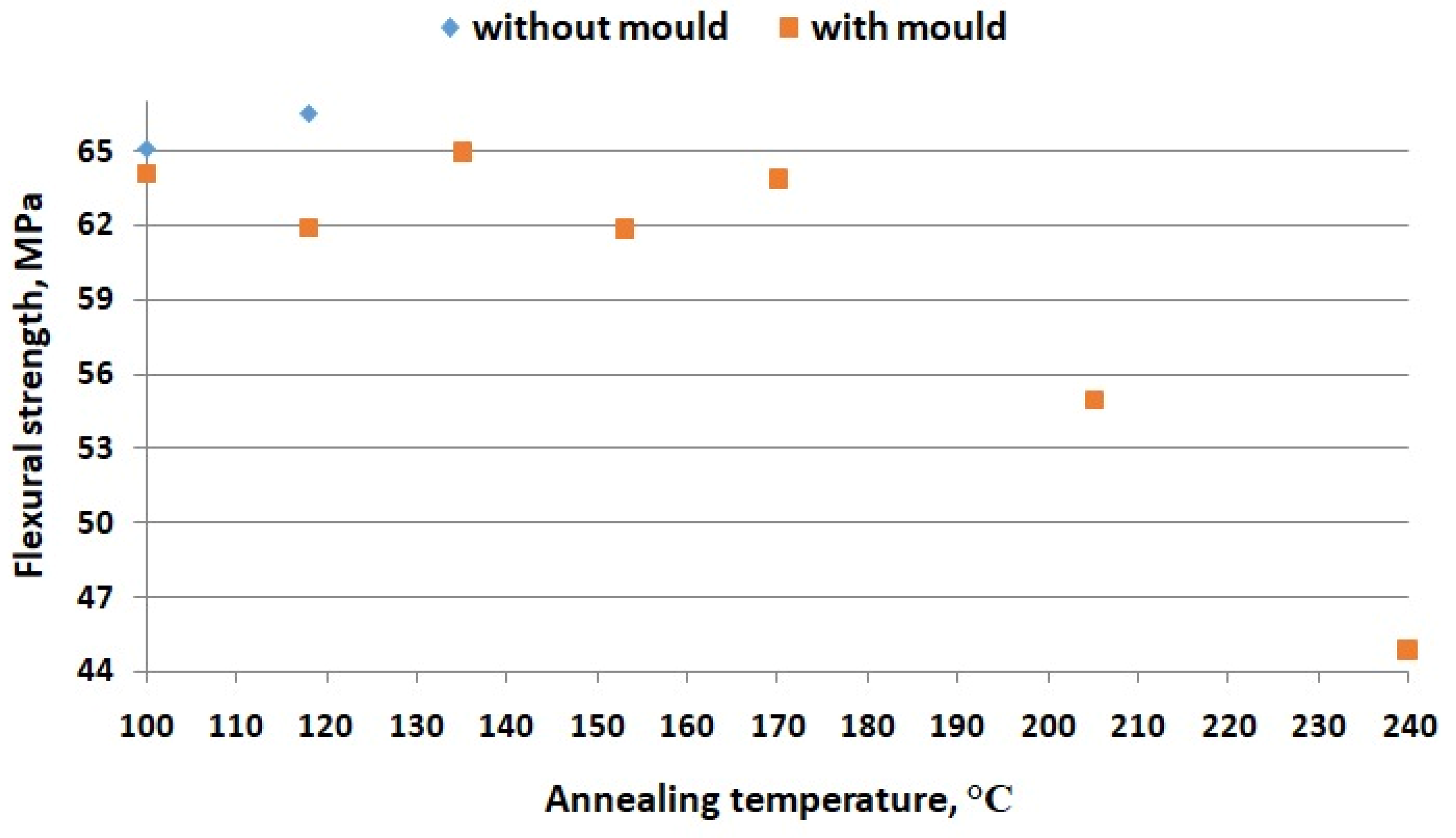
| Sunil Bhandari, Roberto A. Lopez-Anido, Douglas J. Gardner | [39] | ME | PETG and a semi-crystalline PLA | PETG—120 °C—0, 30, 240, 480 min. PETG-CF—120 °C—0, 30, 240, 480 min PLA—120 °C—0, 30, 240, 480 min PLA-CF—120 °C—0, 30, 240, 480 min PLA—90 °C—30, 240, 480 min PLA-CF—90 °C—30, 240, 480 min | Study to improve the interlayer tensile strength of 3D-printed extrusion-based composites using post-process annealing heat treatment. | |
| Pushpendra Yadav, Dheeraj Kumar Angajala, Ishant Singhal, Ankit Sahai, Rahul Swarup Sharma | [31] | ME | PLA | 80 °C and 120 °C and left in the oven for cooling down | Investigation of the effect of infill density and annealing temperature on mechanical properties of polylactic acid (PLA)-based 3D-printed parts. | |
| P.D. Nezhadfar, Rakish Shrestha, Nam Phan, Nima Shamsaei | [76] | L-PBF | 17-4 PH stainless steel | Procedures based on ASTM A693: H900—482 °C, 1 h, Air cooled H1025 + 552 °C, 4 h, Air cooled CA-H900—1050 °C, 0.5 h, Air cooled CA-H900—482 °C, 1 h, Air cooled CA-H1025—1050 °C, 0.5 h, Air cooled CA-H1025—552 °C, 4 h, Air cooled CA-H1150—1050 °C, 0.5 h, Air cooled CA-H1150—621 °C, 4 h, Air cooled | Synergistic effects, under monotonic tensile and fatigue loading, of annealing heat treatment and surface roughness on the microstructure and mechanical properties of L-PBF precipitation hardening (PH) 17-4 stainless steel (SS). | |
| P.D. Nezhadfar, Emma Burford, Kathryn Anderson-Wedge, Bin Zhang, Shuai Shao, S.R. Daniewicz, Nima Shamsaei | [77] | L-PBF | 17-4 PH stainless steel | CA-H900 includes two steps, first step Condition A (CA), solution heat treatment at 1050 °C for 0.5 h followed by air cooling to room temperature and second step (H900), specimens were held at 482 °C for 1 h followed by air cooling. H1025 condition, only heat treated at 552 °C for 4 h followed by air cooling to room temperature without performing CA step. | Study of the fatigue crack growth (FCG) behavior of precipitation hardening (PH) 17-4 stainless steel (SS) fabricated using the laser powder bed fusion (L-PBF) process and compare it with that of the forged counterpart. | |
| Sudha Cheruvathur, Eric A. Lass, Carelyn E. Campbell | [78] | L-PBF | 17-4 PH stainless steel | The temperatures and times of heat treatment were selected as 650 °C and 1050 °C for 1 h and 1150 °C for 2 h, respectively, to comply with the EOS technical specification, wrought solution heat treatment, condition A, and AMS 5355 homogenizing heat treatment. | Study of the effects of annealing heat treatment and surface roughness on the microstructure and mechanical properties of L-PBF precipitation hardened (PH) 17-4 stainless steel (SS). | |
| Agnieszka Chmielewska, Bartłomiej Wysocki, Piotr Kwasniak, Mirosław Jakub Kruszewski, Bartosz Michalski, Aleksandra Zielinska, Bogusława Adamczyk-Cieslak, Agnieszka Krawczynska, Joseph Buhagiar, Swįeszkowski | [79] | L-PBF | Ni55.7Ti44.3 SMAs | Heat treatment 1—1100 °C, 10 h Heat treatment 2—900 °C, 24 h Heat treatment 3—900 °C, 24 h + 1150 °C, 24 h | Analysis of the influence on chemical and phase composition heterogeneity of annealing treatments with different parameters. | |
| Hardikkumar Prajapati, Divya Chalise, Darshan Ravoori, Robert M. Taylor, Ankur Jain | [42] | ME | ABS | 135 °C for 96 h. | Study of the effect of annealing temperature and time on the increase in thermal conductivity, investigated experimentally. | |
| Heather Simmons, Praphulla Tiwary, James E. Colwell, Marianna Kontopoulou | [80] | Melting and Shaping | ABS | Temperatures between 80 °C and 120 °C. | Investigation of strategies to improve the crystallinity and mechanical properties of PLA without compromising its hydrolytic degradation behavior. | |
| Sisi Wang, Lode Daelemans, Rudinei Fiorio, Maling Gou, Dagmar R. D’hooge, Karen De Clerckm Ludwig Cardon | [44] | ME | PLA/PHB blend | 80 °C and 100 °C for 0.5 h, 1 h, and 2 h. | Analysis of gap-bridging strategies to apply conventional processing optimizations to the 3D printing domain and to specifically enhance the mechanical performance of additive extrusion-based manufacturing of PLA filaments by annealing and/or blending with PHB. | |
| Kevin R. Hart, Ryan M. Dunn, Jennifer M. Sietins, Clara M. Hofmeister Mock, Michael E. Mackay, Eric D. Wetzel | [51] | ME | ABS | 75 °C for 18 h, 125 °C for 2 h, 125 °C for 18 h, 135 °C for 2 h, 135 °C for 18 h, 135 °C for 41 h, 135 °C for 72 h, 135 °C for 168 h, 175 °C for 2 h, 175 °C for 18 h | Investigation of the fracture toughness behavior of polymer samples using additive technologies followed by isothermal annealing heat treatments. | |
| Radoslaw A. Wach, Piotr Wolszczak, Agnieszka Adamus-Wlodarczyk | [45] | ME | PLA | Temperatures between 65 °C and 95 °C | Study of the possibility of improving the mechanical properties of samples made from PLA using RM technology by increasing the degree of crystallinity of PLA using a post-process thermal annealing treatment. | |
| Agata Baran, Marek Polanski | [81] | LENS | Ni-Ti SMA | 600 °C in a resistance furnace inside a glovebox (MBRAUN LABmaster) with an argon atmosphere (<1 ppm O2 and H2O) | Investigation of the influence of the deposition rate on the microstructure and phase composition of the Ni-Ti SMA. | |
| Therese Bormann, Bert Müller, Michael Schinhammer, Anja Kessler, Peter Thalmann, Michael de Wild | [12] | L-PBF | Ni-Ti SMA | 800 °C, 0.5 h under argon atmosphere and subsequently water quenched. | Investigation of the effect of laser power, scan speed, and laser trajectory on the microstructure of NiTi SMA parts produced by L-PBF technology and treated by annealing after orientation. | |
| Vidya Kishore, Xun Chen, Ahmed Arabi Hassen, John Lindahl, Vlastimil Kunc, Chad Duty | [46] | ME | PPS composites | Isothermal 250 °C, 18 h | Study of the influence of post-process isothermal annealing treatment on the mechanical properties of different classes of carbon fiber-reinforced PPS components produced by Big Area Additive Manufacturing (BAAM) printing. | |
| Nan Yi, Richard Davies, Adam Chaplin, Paul McCutchion, Oana Ghita | [47] | ME | PAEK (PEEK 151, AM 200) | LAT—156 °C, 2 h for PEEK151 and 170 °C, 2 h for AM 200. HAT—200 °C, 4 h for both PAEK grades. | Comparison of crystallization kinetics, morphology, and mechanical properties for parts made from two different PAEK polymers used in material extrusion (ME): fast crystallizing PEEK151 grade, originally designed for injection molding, and slow crystallizing AM 200 grade, specifically designed for ME and post-treated. | |
| Sheng Li, Hany Hassanin, Moataz M. Attallah, Nicholas J.E. Adkins, Khamis Essa | [19] | L-PBF | Ti56Ni44 SMA | Heat Treatments 1—950 °C, 3 h and Heat Treatments 2—1000 °C, 2 h, both followed by water quench. | Evaluation of the influence of L-PBF process parameters (laser power, scanning speed, and track spacing) on microstructure development and structural integrity in a Ti-rich TiNi alloy, as well as the influence of a post-process homogenization treatment on microstructure and phase transformations. | |
| Bo Song, Shujuan Dong, Qi Liu, Hanlin Liao, Christian Coddet | [3] | L-PBF | pure iron powder (product specification MH 300) | Vacuum annealing at 640 °C with a heating rate of 20 °C /min and held for 2.5 h and then cooled within the furnace to the room temperature. | Study of the effects of vacuum annealing heat treatment on the phase structure, microstructure, residual stresses and tensile strength of parts produced by L-PBF technology from pure iron powder. | |
| Rhugdhrivya Rane, Akhilesh Kulkarni, Hardikkumar Prajapati, Robert Taylor, Ankur Jain, Victoria Chen | [33] | ME | ABS | Temperatures between 120 °C and 180 °C, 3 h | Experimental study of the effect of annealing with simultaneous application of an initial uniaxial load to characterize the increase in tensile strength. | |
| Amal Nassar, Mona Younis, Mohamed Elzareef, Eman Nassar | [26] | ME | PLA reinforced with 9% carbon fiber—PLACF, ABS reinforced with 9% carbon fiber—ABSCF | 50 °C, 120 °C and 150 °C, 10 min | Investigation of the effects of annealing heat treatment on the tensile behavior of 3D-printed high modulus carbon fiber-reinforced materials. | |
| Marcus Ivey, Garrett W. Melenka, Jason. P. Carey, Cagri Ayranci | [48] | ME | PLACF | 85 °C, 115 °C and 145 °C, 2 h | Investigation of the effects of annealing heat treatment on the tensile behavior of 3D-printed high modulus carbon fiber-reinforced materials. | |
| Jairo Alberto Munoz, Sergio Elizalde, Alexander Komissarov, José María Cabrera | [82] | L-PBF | AlSi11Cu | 200 °C, 300 °C, 400 °C, 500 °C, and 550 °C, 1 h, cooling in water (550 °C water temperature). | Study of the effect of different heat treatments on the mechanical, anisotropic and microstructural behavior of a hypoeutectic, near eutectic AlSi11Cu alloy obtained by L-PBF technology. | |
| John W. Elmer, Karl Fisher, Gordon Gibbs, John Sengthay, Dave Urabe | [67] | WAAM | 304L Stainless Steel | Recrystallization at 650 °C, 850 °C and 1050 °C, 0.5 h. | Investigation of how thermomechanical processes, in particular rolling followed by annealing, can improve the mechanical properties and reduce or eliminate anisotropy in the microstructure of 304L stainless steel parts produced by WAAM technology. | |
| Zhen Zhang, Liqing Wang, Ruize Zhang, Dezheng Yin, Zhanyong Zhao, Peikang Bai, Bin Liu, Fude Wang | [68] | WAAM | Mg17Al12—AZ91 Mg alloy | Solution annealing (415 °C for 8 h) | Investigation by microstructural analysis and electrochemical measurements of the effect of solution annealing on the microstructure and corrosion behavior of magnesium alloy AZ91 wire and WAAM in 0.1 M NaCl. | |
| V. Salarvand, H. Sohrabpoor, M.A. Mohammadi, M. Nazari, R. Raghavendra, A. Mostafaei, D. Brabazon | [83] | L-PBF | Austenitic stainless steel 316L | 900 °C and 1000 °C | Investigation of the effect of heat treatments with different parameters on the electrochemical corrosion performance of 316L stainless steel parts produced by additive technology compared to untreated parts. | |
| Yabao Hu, Hanning Chen, Xiaohui Jia, Xiaodan Liang, Jianbo Lei | [8] | L-PBF | Pure Titanium TA1 | 550 °C, 650 °C and 750 °C, 2 h | Study of the influence of heat treatment applied to titanium components produced by laser beam bed fusion on structural and mechanical properties (tensile strength). | |
| Ariadna Chueca de Bruijn, Giovanni Gómez-Gras, Marco A. Pérez | [40] | ME | ULTEMTM 9085 | 180 °C, 1 h, vacuum 190 °C, 2 h 200 °C, 3 h | Study of the influence of thermal annealing above the glass transition temperature as an efficient post-processing technique applied to specimens produced by ME additive technology from ULTEM material and surface finishing of printed parts on mechanical performance. | |
| Alessandro Carrozza, Alberta Aversa, Paolo Fino, Mariangela Lombardi | [84] | L-PBF | Ti-6Al-2Sn-4Zr-6Mo alloy | HT600—600 °C, 2 h, furnace cooling. HT750—750 °C, 2 h, furnace cooling. HT875—875 °C, 2 h, furnace cooling. HT950—950 °C, 2 h, furnace cooling. | Study of the phenomena occurring in the microstructure of Ti-6Al-2Sn-4Zr-6Mo alloy parts produced by L-PBF additive technology and subjected to heat treatments with different parameters, and how these transformation phenomena affect their mechanical properties. | |
| Jinghao Xu, Håkan Brodin, Ru Lin Peng, Vladimir Luzin, Johan Moverare | [85] | L-PBF | Nickel-base superalloy CM247LC | Temperatures between 550 °C and 1260 °C, 2 h. | Study of the structural behavior of CM247LC nickel-base superalloy parts produced by L-PBF additive technology and subjected to a wide range of post-processing heat treatments with different parameters. | |
| Easir Arafat Papon, Anwarul Haque, Scott K. Spear | [41] | ME | PLACF | 80 °C, 2 h, slow cooling in vacuum. | Determination of the effects of acid-based fiber oxidation treatment on fiber–matrix interfacial bonding and post-fabrication vacuum annealing heat treatment on the microstructure, fiber bonding and mechanical properties of fiber-reinforced composite parts produced by 3D printing based on ME technology. | |
| Peng Geng, Ji Zhao, WenzhengWu, Yulei Wang, Bofan Wang, Shuobang Wang, Guiwei Li | [56] | ME | PPS | 125 °C, 2 h, 150 °C, 2.25 h, 200 °C, 2.5 h, 225 °C, 2.5 h, dried at 120 °C, 12 h to remove moisture. | Analysis of the effects of varying thermal processing and heat treatment conditions on the accuracy and mechanical properties of 3D ME-printed PPS samples. | |
| Isaac Ferreira, Carolina Melo, Rui Neto, Margarida Machado, Jorge Lino Alves, Sacha Mould | [43] | ME | Polyamide 12 (PA 12) CF15 short carbon fibers reinforced FX256 unreinforced CF15. | 135 °C, 150 °C, 165 °C during 3 h, 6 h, 12 h or 18 h | Evaluate and compare the mechanical performance of ME parts when further post-processed by heat treatment by conducting a study on the influence of annealing on mechanical properties. | |
| Niranjan Chikkanna, Shankar Krishnapillai, Velmurugan Ramachandran | [57] | ME | PLA | 70 °C, 15 min, 37.5 min, 1 h; 90 °C, 15 min, 37.5 min, 1 h; 110 °C, 15 min, 37.5 min, 1 h. | Study of the effect of annealing heat treatment on ME-printed PLA parts under static and dynamic flexural loading conditions on flexural properties. | |
| Yongjie Zhang, Seung Ki Moon | [35] | ME | ULTEMTM 9085 | 170 °C, 24 h, 170 °C, 96 h 180 °C, 24 h, 180 °C, 96 h | Analysis of the influence of a proposed new thermal annealing method to improve the mechanical properties of parts produced by ME. | |
| Ju Dong, Xingyan Huang, Pranjali Muley, Tongyao Wu, Mohamad Barekati-Goudarzi, Zhengjie Tang, Meichun Li, Sunyoung Lee, Dorin Boldor, Qinglin Wu | [49] | ME | PLA composite with CCNFs | 25 °C to 250 °C, 0.5 min to 2 h, with heating rate of 5 °C /min. | Demonstrate the effectiveness of microwave heating to anneal 3D-printed PLA composites and increase scientific understanding of using CCNFs as dielectric heat sources to manipulate PLA thermoplastic crystallinity and mechanical properties under microwave irradiation. | |
| Behnam Akhoundi, Mojtaba Nabipour, Faramarz Hajami, Diana Shakoori | [50] | ME | HTPLA | 110 °C, 1 h | Analysis of the effect of nozzle temperature and annealing heat treatment on the mechanical properties of high-temperature PLA parts produced by ME. | |
| Joaquín Lluch-Cerezo, María Desamparados Meseguer, Juan Antonio García-Manrique, Rut Benavente | [27] | ME | ABS and PLA | 100 °C, 118 °C, 135 °C, 153 °C, 170 °C, 205 °C, 240 °C, cooling with the furnace to room temperature for ABS 63 °C, 75 °C, 86 °C, 98 °C, 109 °C, 132 °C, 155 °C, cooling with the furnace to room temperature for PLA | Study of the influence of a ceramic powder mold and post annealing process of two of the most widely used thermoplastic materials in this type of additive technique—ABS and PLA printed by ME on the mechanical properties of parts. | |
| Musa Yilmaz, Necip Fazil Yilmaz, Mahmut Furkan Kalkan | [58] | ME | PEI/ULTEMTM 1010 | 220 °C, 225 °C, 230 °C, 235 °C for 3 h | Establishment of heat treatment thresholds to improve interlayer adhesion strength of 3D-printed PEI thermoplastics. | |
| Hot Isostatic Pressing | J.-R. Poulin, A. Kreitcberg, V. Brailovski | [86] | L-PBF | Inconel 625 | High temperatures to promoting recrystallization and isostatic compression applied by a pressurized gaseous atmosphere (often argon) | Evaluation of the effect of HIP treatment on the size and distribution of residual defects, microstructure and mechanical properties of IN625 material fabricated by L-PBF with intentionally induced defects. |
| Dennise Tanoko Ardi, Lim Guoweia, Niroj Maharjana, Bisma Mutiargoa, Seng Hwee Lengb, Raghavan Srinivasana | [87] | L-PBF | Inconel 718 | HIP at 980 °C, 100 MPa and 4 h and shot peening at 0.45 mmA intensity and 200 % coverage. | Comprehensive investigation of the fatigue performance of Inconel 718 parts produced by L-PBF with different post-processing parameters. | |
| Yutao Zhai, Bo Huang, Xiaodong Mao, Mingjie Zheng | [5] | L-PBF | CLAM | HIP (holding at 1150 °C, 150 MPa for 180 min) and SHT (980 °C for 30 min followed by water cooling, then holding at 740 °C for 90 min and subsequently cooled by air). | Investigation and evaluation of the microstructure and mechanical properties of the L-PBF fabricated CLAM at as-built, standard heat treatment (SHT) and HIP and SHT. | |
| A. du Plessis, E. Macdonald | [88] | L-PBF | Ti6Al4V | HIP + Annealing heat treatment at 900 °C, 3 h. | Study of the porosity reduction behavior of Ti6Al4V samples made with L-PBF by applying HIP followed by homogenization annealing. | |
| Hui Wang, Liu Chen, Bogdan Dovgyy, Wenyong Xu, Aixue Sha, Xingwu Li, Huiping Tang, Yong Liu, Hong Wu, Minh-Son Pham | [89] | L-PBF | Hastelloy-X | 1176,85 °C for 4 h in vacuum, and then furnace-cooled while HIP was conducted at a hydrostatic pressure of 150 MPa, a temperature of 1176,85 °C for 4 h, then slowly cooled in the furnace at a cooling rate of about 12 °C × min−1. | Analysis of literature data to identify optimized printing parameters and evaluation of the strengthening, microstructure and mechanical properties of Hastelloy-X samples produced by laser powder bed fusion and study of the effects of post-processing annealing and HIP on microstructure and mechanical properties. | |
| P. Ajith Kumar Jain, S. Sattar, D. Mulqueen, D. Pedrazzoli, S.G. Kravchenko, O. G. Kravchenko | [52] | ME | PA 6 | 0.55 MPa (80 psi) and 200 °C Annealing carried out in a closed oven with ambient air at 150 °C, 170 °C and 200 °C, respectively. | Analysis of the effect of isostatic pressure and annealing heat treatment on improving the mechanical properties of 3D-printed short fiber polymer composites. | |
| Erica Liverani, Adrian H. A. Lutey, Alessandro Ascari, Alessandro Fortunato | [7] | L-PBF | Austenitic stainless steel 316L | HIP50—1150 °C, 50 bar, 3 h HIP1050—1150 °C, 1050 bar, 3 h HIP1500—1150 °C, 1500 bar, 3 h HIP2000—1150 °C, 2000 bar, 3 h. | Investigation of hot isostatic pressing (HIP) in a nitrogen protective environment and solubilizing heat treatment as methods for improving the quality of 316L stainless steel components produced by L-PBF. | |
| J.M. Alegre, A. Díaz, R. García, L.B. Peral, I.I. Cuesta | [21] | L-PBF | Ti-6Al-4V | Argon environment, pressure of 200 MPa and 850 °C, 2 h and fast-cooling. | Study of the effect of an unconventional HIP cycle on the fatigue behavior of parts made from a Ti-6Al-4V alloy using the L-PBF technique. | |
| I.S. Grech, J.H. Sullivan, R.J. Lancaster, J. Plummer, N.P. Lavery | [90] | L-PBF | Austenitic stainless steel 316L | 1—HIP (T700 P100)—700 °C, 100 MPa 2—HIP (T1125 P100)—1125 °C, 100 MPa 3—HIP (T1200 P100)—1200 °C, 100 MPa 4—HIP (T700 P137)—700 °C, 137 MPa 5—HIP (T1125 P137)—1125 °C, 137 MPa 6—HIP (T1200 P137)—1200 °C, 137 MPa 7—HIP (T700 P200)—700 °C, 200 MPa 8—HIP (T1125 P200)—1125 °C, 200 MPa 9—HIP (T1200 P200)—1200 °C, 200 MPa 10—As-built Not Applicable Not Applicable 11—HIP (T1125 P200—long hold)—1125 °C, 137 MPa | Comparative analysis of the mechanical and corrosion properties of 316L steel produced by L-PBF and subsequently treated by HIP with various parameters. | |
| G.E. Bean, T.D. McLouth, D.B. Witkin, S.D. Sitzman, P.M. Adams, R.J. Zaldivar | [24] | L-PBF | Inconel 718 | HIP at 1160 °C, 1020 atm, solution treatment at 955 °C, 1 h, water quenching, then precipitation treatment at 720 °C, 8 h followed by furnace cool at 55 °C/h to 620 °C and held for 18 h | Investigation of the variation in tensile properties of specimens made by additive L-PBF technology at different angles to the direction of construction from Inconel 718 material, heat treated and tensile tested at room temperature. | |
| Nekoda van de Werken, Pratik Koirala, Jafar Ghorbani, Derek Doyle, Mehran Tehrani | [53] | ME | CF-reinforced PEEK composite | 200 °C, 250 °C, 300 °C, at 200 psi | Investigation of interlaminar shear behavior, flexural, tensile and compressive mechanical properties when using HIP for post-processing of AM continuous carbon fiber-reinforced PEEK composites. | |
| Ageing | Sabrina Bodziak, Kassim S. Al-Rubaie, Luiz Dalla Valentina, Fernando Humel Lafratta, Edson Costa Santos, André Marcon Zanatta, Yimeng Chen | [15] | L-PBF | maraging 300 steel | 510 °C, 2 h and then air-cooled. | Study of the composition and morphology of precipitates in the structure of samples of 300 steel maraged by L-PBF and post-treated by aging at 510 °C for 2 h. |
| Soheil Saedi, Ali Sadi Turabi, Mohsen Taheri Andani, Narges Shayesteh Moghaddam, Mohammad Elahinia, Haluk Ersin Karaca | [17] | L-PBF | Ni50.8Ti49.2 SMA | Temperatures from 350 °C to 600 °C for 30 min, 1 h and 1.5 h. | Study of the effect of laser beam bed fusion (L-PBF) fabrication on the microstructure and texture of Ni-rich NiTi alloy and aging heat treatment parameters (aging time and temperature) on transformation behavior. | |
| Shuo Yin, Chaoyue Chen, Xingchen Yan, Xiaohua Feng, Richard Jenkins, Peter O’Reilly, Min Liu, Hua Li, Rocco Lupoi | [20] | L-PBF | Maraging 18Ni-300 steel | Various temperatures from 390 °C to 590 °C and time from 1 h to 7 h without pre-solution treatment. | Study of the influence of aging temperature and time on the microstructure, mechanical properties (hardness, strength and ductility), and tribological properties (wear-resistance) of 18Ni-300 maraging L-PBF steel. | |
| Seong Jun Park, Seong Je Park, Yong Son, Il Hyuk Ahn | [54] | ME | ABS | 100 bar and 350 °C, 1 h. | Analysis of the influence of aging heat treatments and application of hot isostatic pressure (WIP) on the mechanical properties and anisotropy of ABS parts produced by material extrusion technology. | |
| Mohammad Reza Khosravani, Zeljko Bozic, Ali Zolfagharian, Tamara Reinicke | [55] | ME | PLA | Temperature range of −5 °C, 5 h to +35 °C, 5 h. | Analysis of the influence of defects and accelerated thermal aging on the mechanical performance of samples made from PLA material using additive ME technology. | |
| Lihua Zhang, Wanqing Cao, Yun Zhang, Ripeng Jiang, Xiaoqian Li | [70] | WAAM | Al-Zn-Mg-Li alloy | Solute treatment 470 °C, 5 h and quenching. Two-stage aging at 120 °C, 6 h and 170 °C, 10 h. | Comparative studies to analyze the influence of multidirectional technologies consisting of forging and aging treatments on the microstructure evolution and mechanical properties of Al-Zn-Mg-Li alloy parts using additive technology. | |
| Complex Treatments | Chuncheng Yang, Xiaoyong Tian, Dichen Li, Yi Cao, Feng Zhao, Changquan Shi | [28] | ME | PEEK | Air cooling from 100 °C to 20 °C, 10 min Furnace cooling from 100 °C to 20 °C, 10 min Quenching from 100 °C to 20 °C, 1 min Annealing, heating 20 min from 100 °C to 200 °C, holding 40 min and cooling to 20 °C in 60 min. Tempering, heating 30 min from 20 °C to 250 °C, holding 70 min and cooling to 20 °C in 80 min. | Calculate crystallinity and perform strength tests on samples subjected to different heat treatment conditions in the ME process and compare the results with the crystallinity and mechanical properties (tensile strength, Young’s modulus, and elongation) of the non-heat-treated PEEK material. |
| Wei Zhang, Ali Chabok, Bart J. Kooi, Yutao Pei | [1] | L-PBF process | CoCrFeMnNi HEAs systems, | HIP, Annealing, Aging Heat Treatment | Study of the influence of post-treatment on the evolution of the resulting microstructure, relative structure, density, residual stress, grain structure, texture and dislocation networks, element distribution, precipitation, and mechanical properties including hardness, mechanical strength, compressive properties, cryogenic and high temperature properties, fatigue, creep. | |
| Ali N. Alagha, Shahadat Hussain, Wael Zaki | [91] | L-PBF and DED, LDED additive manufacturing | SMAs—NiTi. | Aging and Solution Annealing | Analysis of the application of additive manufacturing to different SMA systems, with a focus on the influence of process parameters and heat treatment on microstructure, printability and structural changes. | |
| Guodong Zhang, Neng Li, Jianshi Gao, Huaping Xiong, Huai Yu, Hong Yuan | [62] | Wire-fed EB-DED | Titan alloy—Ti-6Al-2Zr-1Mo-1V | Post-deposition single annealing treatment at 950 ◦C for 2 h, Air in an electrical resistance | Study of the effect of a single post-deposition annealing treatment on microstructure, texture, and tensile property anisotropy. | |
| Beth A. Bimber, Reginald F. Hamilton, Jayme Keist, Todd A. Palmer | [92] | LDED | NiTi—SMAs | Solutionized (1050 °C, 10 h in an inert environment) and aged (400 °C or 500 °C, for times ranging from 1 to 5 h) before mechanical deformation of austenite | Investigation of the relationship between microstructural anisotropy and over elasticity in large fabricated structures using directed energy deposition additive manufacturing. | |
| Chola Elangeswaran, Antonio Cutolo, Gokula Krishna Muralidharan, Charlotte de Formanoir, Filippo Berto, Kim Vanmeensel, Brecht Van Hooreweder | [93] | L-PBF | 316L steel | Stress relief (SR) heat treatment was carried out at 470 ° C for 5 h in argon atmosphere. | Investigation of the influence of subsequent treatments on the fatigue properties of 316L stainless steel produced by Laser Powder Bed Fusion. | |
| F.F. Conde, J.D. Escobar, J.P. Oliveira, M. Béreš, A.L. Jardini, W.W. Bose, J.A. Avila | [9] | L-PBF | 18 Ni maraging 300 steel | Homogenization cycles were applied between 820 and 980 °C for 1 h, then, two fast cycling steps of 5 min of soaking time were applied at 690 and 720 °C. Finally, aging was conducted at 420 and 480 °C using soaking times of 3 and 6 h. | Study the martensite-to-austenite reversion and its effect on hardness and bending strength after laser beam bed fusion of a maraging 300 steel. | |
| M S I N Kamariah, W S W Harun, N Z Khalil, F Ahmad, M H Ismail, S Sharif | [94] | L-PBF | 316L stainless steel | Different heat treatments of 650 °C, 950 °C, and 1100 °C for 2 h. | Investigation of the effect of heat treatments on the microhardness of compact parts made by L-PBF from 316L stainless steel. | |
| Bandar AlMangour, Jenn-Ming Yang | [64] | DMLS | 17-4 stainless steel | 80 °C, argon atmosphere | Study to test induced grain refinement by shot peening (SP) to improve the physical and mechanical properties of 17-4 stainless steel components produced by DMLS. | |
| Chaolin Tan, Kesong Zhoua, WenyouMa, Panpan Zhang, Min Liu, Tongchun Kuang | [11] | L-PBF | Maraging 300 steels | 490 °C, 6 h for age hardening and a solution treatment 840 °C, 1 h, followed by aging at 490 °C for 6 h for comparison. All heat treatments were protected in argon atmosphere and air cooled after holding. | Characterization and analysis of microstructural evolution, nanoprecipitation behavior, and mechanical properties of parts made from maraging 300 steels by L-PBF technology and heat treated. | |
| Christoph Haberland, Mohammad Elahinia, Jason M Walker, Horst Meier, Jan Frenzel | [13] | L-PBF | Ni-Ti SMA | Annealing: 949.85 °C, 5.5 h, H2O aging: 349.85 °C, 24 h, H2O | How additive manufacturing and post-process heat-treated parts through annealing and aging affect the structural and functional properties of NiTi SMA parts, and how additive manufacturing can be influenced by optimal setting of process parameters to produce high quality NiTi SMA parts and components. | |
| James Mutua, Shinya Nakata, Tetsuhiko Onda, Zhong-Chun Chen | [14] | L-PBF | Maraging 300 steels | Solution treatment (annealing) at 820 °C, 1 h and aging at 460 °C, 5 h. | Study of the influence of different process parameters on the densification behavior, surface morphology, microstructure, and mechanical properties of parts produced by L-PBFed from post-heat-treated maraging 300 steel. | |
| Soheil Saedi, Sayed E. Saghaian, Ahmadreza Jahadakbar, Narges Shayesteh Moghaddam, Mohsen Taheri Andani, Sayed M. Saghaian, Y. Charles Lu, Mohammad Elahinia, Haluk E. Karaca1 | [16] | L-PBF | Ni-Ti SMA | Samples placed in argon-filled quartz vials, separated using ceramic barriers and pure titanium to avoid oxidation, were solution annealed at 950 °C for 5.5 h in an oven and then quenched in water. Aging was performed in a vacuum at 350 °C for 15 min, followed by quenching in water. | Analysis of techniques to improve the superelasticity and thermo-mechanical properties of porous NiTi structures produced by additive technology and then heat-treated (solution annealing + aging at 350 °C for 15 min). | |
| Soheil Saedi, Ali Sadi Turabi, Mohsen Taheri Andani, Christoph Haberland, Haluk Karaca, Mohammad Elahinia | [18] | L-PBF | Ni50.8Ti49.2 SMA | Annealed at 950 °C, 5.5 h and then water quenched and aging at 350 °C and 450 °C, with time varied from 5 min up to 18 h. | Study of the effects of solution annealing and subsequent aging treatment on the shape memory behavior of Ni-rich Ni50.8Ti49.2 produced by laser beam bed fusion. | |
| Agnieszka Szust, Grzegorz Adamski | [32] | ME | PETG | Annealed at 60 °C, 1 h and 80 °C, 1 h. Salt remelting at 230 °C, 2 h. | Investigation of the effects of AM process parameters (print orientation and layer height), annealing heat treatment and salt re-melting process on the tensile strength and anisotropy of ME parts. | |
| Konrad Gruber, Patrycja Szymczyk-Ziołkowska, Szymon Dziuba, Szymon Duda, Paweł Zielonka, Stanislav Seitl, Grzegorz Lesiuk | [95] | L-PBF | Inconel 718 | Variant A: Stress relief—1065 °C, 1.5 h; Hot isostatic pressing—n/a; Solutioning—1065 °C, 1 h; Ageing—720 °C, 8 h to 620 °C, 10 h; Argon atmosphere. Variant B: Stress relief—1065 °C, 1.5 h; Hot isostatic pressing—1150 °C, 4 h, 100 MPa; Solutioning—1065 °C, 1 h; Aging—720 °C, 8 h to 620 °C, 10 h; Argon atmosphere. | Study of the fatigue crack growth rate (FCGR) of Inconel 718 parts additively manufactured by laser powder bed fusion (L-PBF) and subjected to post-process heat treatment in two variants: without hot isostatic pressing (variant A) and with hot isostatic pressing (variant B). | |
| Santiago Aguado-Montero, Carlos Navarro, Jesús Vazquez, Fernando Lasagni, Sebastian Slawik, Jaime Domínguez | [67] | L-PBF (PBF) | TI6AL4V | SP, SP + CASE, LP and annealing 730 °C for 2 h, slow cooling in the furnace, high-vacuum argon atmosphere. | Investigation of the effect of surface treatments such as SP, SP + CASE, and LP on the fatigue behavior of Ti6Al4V specimens produced by additive-additive technology compared to specimens annealed and sandblasted only after AM, used as a reference. | |
| Shahriar Afkhami, Vahid Javaheri, Edris Dabiri, Heidi Piili, Timo Bjork | [96] | L-PBF | 13Cr10Ni 1.7Mo2Al 0.4Mn0.4Si maraging stainless steel | Solution annealing at 850 °C for 30 min, then air cooling to room temperature (20 °C) and aging for 120 min at 525 °C, and, again, air cooling to room temperature | Analysis of the effects of design orientations, heat treatment, and mechanical machining (both as and after machining) on the microstructure, quasi-static mechanical properties, work-hardenability, strain-hardenability, notch toughness, and residual stress of maraging 13Cr10Ni1.7Mo2Al0.4Mn0.4Si stainless steel produced by L-PBF, known under the trade name CX. | |
| Cecilie V. Funch, Kinga Somlo, Thomas L. Christiansen, Marcel A.J. Somers | [22] | L-PBF | 316L stainless steel | HTSN—at 1100 °C, 2 h at 300 mbar partial pressure of nitrogen (N2). Conventional austenitization in a high vacuum furnace at 1050 °C, 10 min. Austenitization at a low partial pressure of 45 mbar at 1080 °C, 10 min to avoid N2 evaporation. | Analysis of the effects of various post-processing thermochemical treatments on the microstructure and properties of austenitic stainless steel parts produced by additive technology. | |
| Kristina Navickaitė, Klaus Nestler, Falko Böttger-Hiller, Carmel Matias, Alex Diskin, Oz Golan, Andrey Garkun, Evgeny Strokin, Roman Biletskiy, Daniel Safranchik, Henning Zeidler | [97] | L-PBF | Titanium alloy 08Cr18Ni10Ti, | PEP and powder blasting combined with PEP PEP process, electrolyte temperature should be between 50 °C and 90 °C, while for the EP process temperatures in a range from 0 °C to 55 °C | Comparative analysis of two polishing machining techniques applied to the surfaces of specimens manufactured using the additive technology for titanium alloys. | |
| Maider Arana, Eneko Ukar, Iker Rodriguez, David Aguilar, Pedro Álvarez | [69] | WAAM | 2319 aluminum | Annealing 535 °C, 1.5 h, water quenching and aging 160 °C, 3 h, 6 h, 9 h, 12 h, 15 h, 18 h and 180 °C, 18 h, 20 h, 22 h, 24 h, 26 h | Analysis of the influence of both deposition strategy (geometry, dwell time between passes and torch movement) and heat treatment on parts with different geometries of 2319 aluminum produced by WAAM technology. | |
| Wolfgang Tillmann, Nelson Filipe Lopes Dias, Dominic Stangier, Christopher Schaak, Simon Höges | [65] | BJP | 17–4 PH stainless steel (X2CrNiMo17-12-2 (AISI 316L) and X5CrNiCuNb16-4 (AISI 630), | Precipitation heat treatment at 1020 °C, 0.5 h with quenching at air (solution treatment) and a second step at 480 °C, 3 h followed by air quenching. DLC coating. | Study of the influence of deposition coatings on additively manufactured steel on the hardness and tribological properties of 17-4 PH material parts produced by BJP additive technology and subjected to complex heat treatments. | |
| X.X. Zhang, A. Lutzb, H. Andrä, M. Lahres, W. Gong, S. Harjo, C. Emmelmann | [98] | L-PBF | AlSi3.5Mg2.5 alloy | Annealing at 380 °C, 1 h Aging at 170 °C, 1 h | Analysis of the influence of the complex post-treatment of annealing followed by aging applied to AlSi3.5Mg2.5 alloy parts produced by additive technology on the mechanical ductility property. | |
| Changhao Pei, Dong Shi, Huang Yuan, Huaixue Li | [23] | L-PBF | Nickel-base superalloy Inconel 718 | Solution treatment (960 °C, 1 h, air cooling) + double aging (720 °C, 8 h, furnace cooling at 55 °C/h to 620 °C, 9.5 h air cooling), and homogenization process (1100 °C, 1.5 h, air cooling) | Investigation of the microstructure, deposition orientation dependence of mechanical properties, and fatigue performance of a nickel based superalloy Inconel 718 produced by L-PBF melting and subsequent heat treatment. | |
| Alessandro Carrozza, Alberta Aversa, Federico Mazzucato, Emilio Bassini, Diego Manfredi, Sara Biamino, Anna Valente, Paolo Fino | [61] | DED | Ti-6Al-4V alloy | Annealing 1050 °C, 1 h, furnace cooled and aging 540 °C, 4 h Annealing 1050 °C, 1 h, air cooled and aging 540 °C for 4 h Annealing 1050 °C, 1 h, water quenched and aging 540 °C for 4 h | Study of the effect of different multi-stage heat treatments on the microstructure, texture, and mechanical properties of Ti-6Al-4V alloy DED products. | |
| Jeferson T. Pacheco, Vitor H. Meura, Paulo Rafael A. Bloemer, Marcelo T. Veiga, Osmar C. de Moura Filho, Alexandre Cunha, Moises F. Teixeira | [99] | LDED | 316L stainless steel | 1040 °C, 2 h, cooling at the room temperature (25 °C) and a cycle of stress relief at 540 °C, 9 h, cooling at the room temperature. | Evaluation of the effect of the deposition direction on the mechanical properties of parts made from AISI 316L material using the L-DED process, in the as-deposited condition and under complex heat treatment conditions. | |
| Bo Zhang, Wu Wei, Wei Shi, Yanwu Guo, Shengping Wen, Xiaolan Wu, Kunyuan Gao, Li Rong, Hui Huang, Zuoren Nie | [100] | L-PBF | Al-7Si-0.6 Mg alloy | DA at 160 °C, 8 h; SR annealing at 300 °C, 2 h; Solution annealing at 540 °C, 1 h, quenching in cold water at room temperature, then, artificial aging at 160 °C, 8 h. | Study of the behavior of Al-7Si-0.6 Mg alloy parts produced by L-PBF technology and subjected to complex heat treatments, in terms of structural changes and mechanical properties (ductility, tensile, and yield strength). | |
| Yaozhong Zhang, Aljoscha Roch | [34] | ME | 17-4PH stainless steel | 1360 °C, 1 h, quenched to room temperature by N2 gas flow (30 L/min); 1360 °C, 1 h, quenched to room temperature by N2 gas flow (30 L/min) and annealed at 550 °C for 4 h; 1360 °C, 1 h, quenched to room temperature by N2 gas flow (30 L/min) and annealed at 1040 °C, 1 h and annealed at 550 °C, 4 h. | Analysis of the behavior of parts made from 17-4PH stainless steel using ME additive technology and subjected to post-work heat treatments in terms of structural changes and mechanical properties. |
| PEEK51 vertical orientation | as printed | LAT 2 h | LAT 4 h | HAT 2 h | HAT 4 h | Difference,% | |||
|---|---|---|---|---|---|---|---|---|---|
| LAT 2 h | LAT 4 h | HAT 2 h | HAT 4 h | ||||||
| Elastic modulus, MPa | 24,000 | 32,000 | 34,000 | 25,000 | 28,000 | 33.33 | 41.67 | 4.17 | 16.67 |
| Strength, MPa | 26 | 24 | 25 | 10 | 18 | −7.69 | −3.85 | −61.54 | −30.77 |
| Elongation at break, % | 2.70 | 2.20 | 2.50 | 0.80 | 1.50 | −18.52 | −7.41 | −70.37 | −44.44 |
| PEEK51 flat orientation | as printed | LAT 2 h | LAT 4 h | HAT 2 h | HAT 4 h | Difference,% | |||
| LAT 2 h | LAT 4 h | HAT 2 h | HAT 4 h | ||||||
| Elastic modulus, MPa | 2800 | 3000 | 3300 | 3100 | 3200 | 7.14 | 17.86 | 10.71 | 14.29 |
| Strength, MPa | 60 | 76 | 72 | 68 | 68 | 26.67 | 20.00 | 13.33 | 13.33 |
| Elongation at break, % | 9 | 13 | 12 | 8 | 13 | 44.44 | 33.33 | −11.11 | 44.44 |
| PEEK51 side orientation | as printed | LAT 2 h | LAT 4 h | HAT 2 h | HAT 4 h | Difference,% | |||
| LAT 2 h | LAT 4 h | HAT 2 h | HAT 4 h | ||||||
| Elastic modulus, MPa | 25,000 | 29,000 | 33,000 | 27,000 | 28,000 | 16.00 | 32.00 | 8.00 | 12.00 |
| Strength, MPa | 50.00 | 48.00 | 46.00 | 60.00 | 46.00 | −4.00 | −8.00 | 20.00 | −8.00 |
| Elongation at break, % | 8.00 | 5.00 | 4.00 | 8.00 | 4.00 | −37.50 | −50.00 | 0 | −50.00 |
| AM200 vertical orientation | as printed | LAT 2 h | LAT 4 h | HAT 2 h | HAT 4 h | Difference,% | |||
|---|---|---|---|---|---|---|---|---|---|
| LAT 2 h | LAT 4 h | HAT 2 h | HAT 4 h | ||||||
| Elastic modulus, MPa | 2200 | 2700 | 2600 | 3100 | 2800 | 22.73 | 18.18 | 40.91 | 27.27 |
| Strength, MPa | 40 | 42 | 44 | 38 | 39 | 5.00 | 10.00 | −5.00 | −2.50 |
| Elongation at break, % | 5.7 | 5.2 | 5 | 3.8 | 4.5 | −8.77 | −12.28 | −33.3 | −21.05 |
| AM 200 flat orientation | as printed | LAT 2 h | LAT 4 h | HAT 2 h | HAT 4 h | Difference,% | |||
| LAT 2 h | LAT 4 h | HAT 2 h | HAT 4 h | ||||||
| Elastic modulus, MPa | 2700 | 3300 | 3200 | 2900 | 2800 | 22.22 | 18.52 | 7.41 | 3.70 |
| Strength, MPa | 50 | 64 | 63 | 58 | 56 | 28.00 | 26.00 | 16.00 | 12.00 |
| Elongation at break, % | 23 | 15 | 14 | 12 | 9 | −34.78 | −39.13 | −47.82 | −60.87 |
| AM 200 side orientation | as printed | LAT 2 h | LAT 4 h | HAT 2 h | HAT 4 h | Difference,% | |||
| LAT 2 h | LAT 4 h | HAT 2 h | HAT 4 h | ||||||
| Elastic modulus, MPa | 2400 | 2600 | 2500 | 3500 | 3300 | 8.33 | 4.17 | 45.83 | 37.50 |
| Strength, MPa | 58 | 70 | 72 | 76 | 66 | 20.69 | 24.14 | 31.03 | 13.79 |
| Elongation at break, % | 17 | 16 | 17.5 | 18 | 14 | −5.88 | 2.94 | 5.88 | −17.65 |
| Material | Annealing Temperature | Interlayer Tensile Strength | Interlayer Young’s Modulus | Interlayer Strain to Failure |
|---|---|---|---|---|
| PLA | 90 °C | Minor increase | No change | Major increase |
| PLA-CF | 90 °C | Major increase | Major increase | Major increase |
| PLA | 120 °C | No change | No change | Minor increase |
| PLA-CF | No change | No change | No change | |
| PETG | No change | No change | Minor increase | |
| PETG-CF | Major increase | Major increase | Major increase |
Disclaimer/Publisher’s Note: The statements, opinions and data contained in all publications are solely those of the individual author(s) and contributor(s) and not of MDPI and/or the editor(s). MDPI and/or the editor(s) disclaim responsibility for any injury to people or property resulting from any ideas, methods, instructions or products referred to in the content. |
© 2023 by the authors. Licensee MDPI, Basel, Switzerland. This article is an open access article distributed under the terms and conditions of the Creative Commons Attribution (CC BY) license (https://creativecommons.org/licenses/by/4.0/).
Share and Cite
Diniță, A.; Neacșa, A.; Portoacă, A.I.; Tănase, M.; Ilinca, C.N.; Ramadan, I.N. Additive Manufacturing Post-Processing Treatments, a Review with Emphasis on Mechanical Characteristics. Materials 2023, 16, 4610. https://doi.org/10.3390/ma16134610
Diniță A, Neacșa A, Portoacă AI, Tănase M, Ilinca CN, Ramadan IN. Additive Manufacturing Post-Processing Treatments, a Review with Emphasis on Mechanical Characteristics. Materials. 2023; 16(13):4610. https://doi.org/10.3390/ma16134610
Chicago/Turabian StyleDiniță, Alin, Adrian Neacșa, Alexandra Ileana Portoacă, Maria Tănase, Costin Nicolae Ilinca, and Ibrahim Naim Ramadan. 2023. "Additive Manufacturing Post-Processing Treatments, a Review with Emphasis on Mechanical Characteristics" Materials 16, no. 13: 4610. https://doi.org/10.3390/ma16134610
APA StyleDiniță, A., Neacșa, A., Portoacă, A. I., Tănase, M., Ilinca, C. N., & Ramadan, I. N. (2023). Additive Manufacturing Post-Processing Treatments, a Review with Emphasis on Mechanical Characteristics. Materials, 16(13), 4610. https://doi.org/10.3390/ma16134610