
Effect of Welding Speed on Microstructure Evolution and Mechanical Properties of Friction Stir Welded 2198 Al-Cu-Li Alloy Joints


Abstract
:1. Introduction
2. Materials and Method
3. Results and Discussion
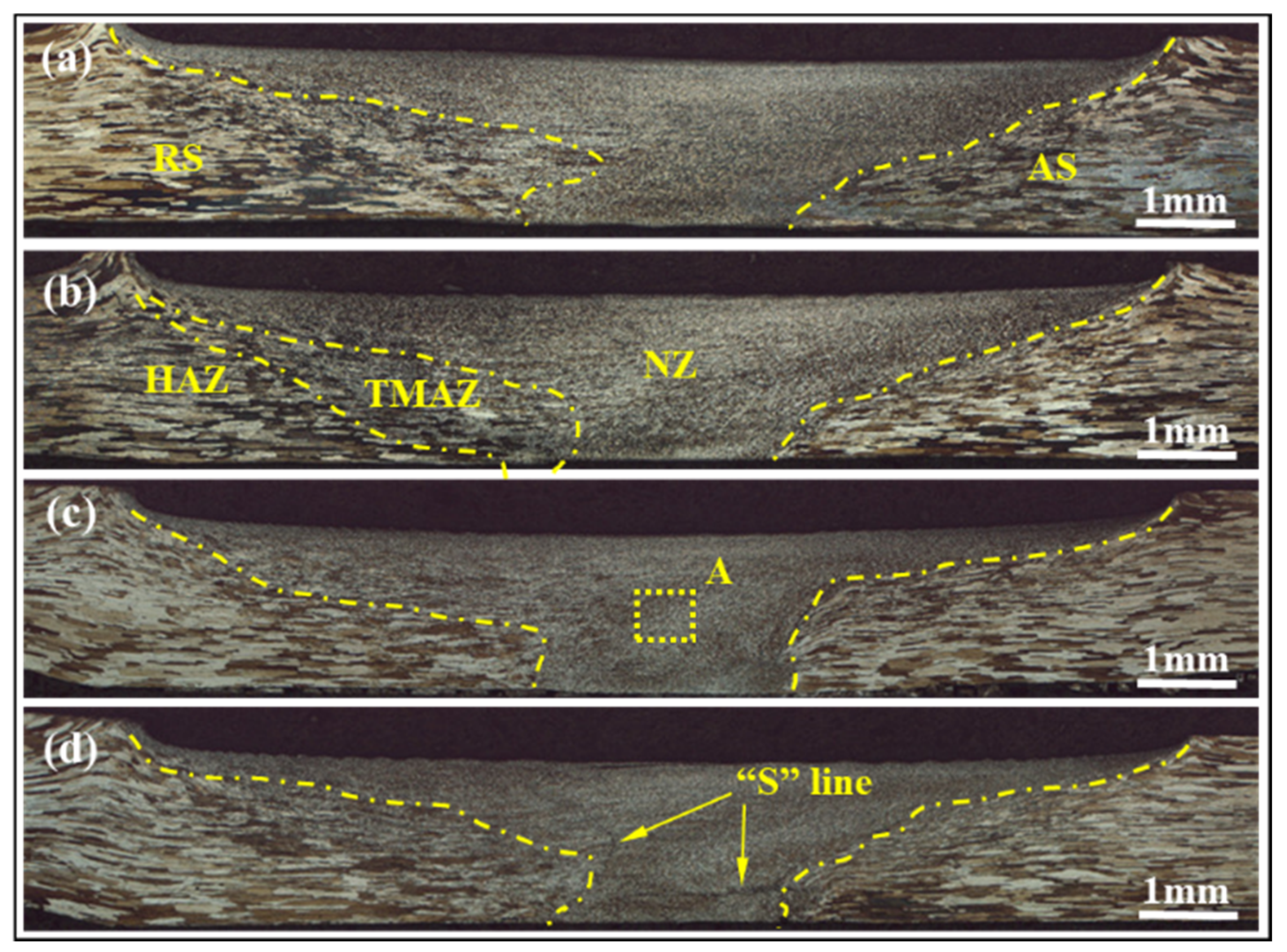
3.1. Macrostructure
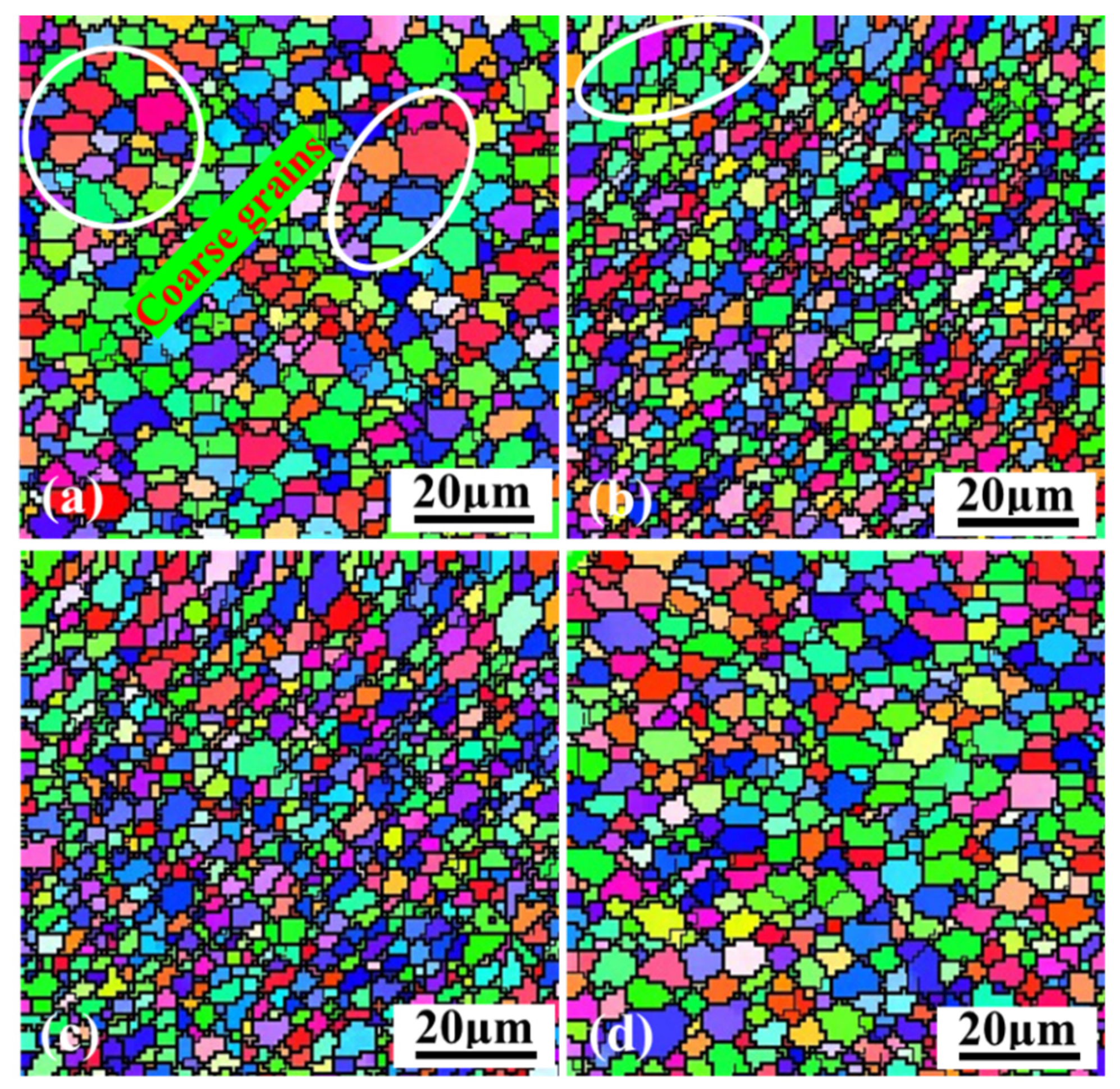
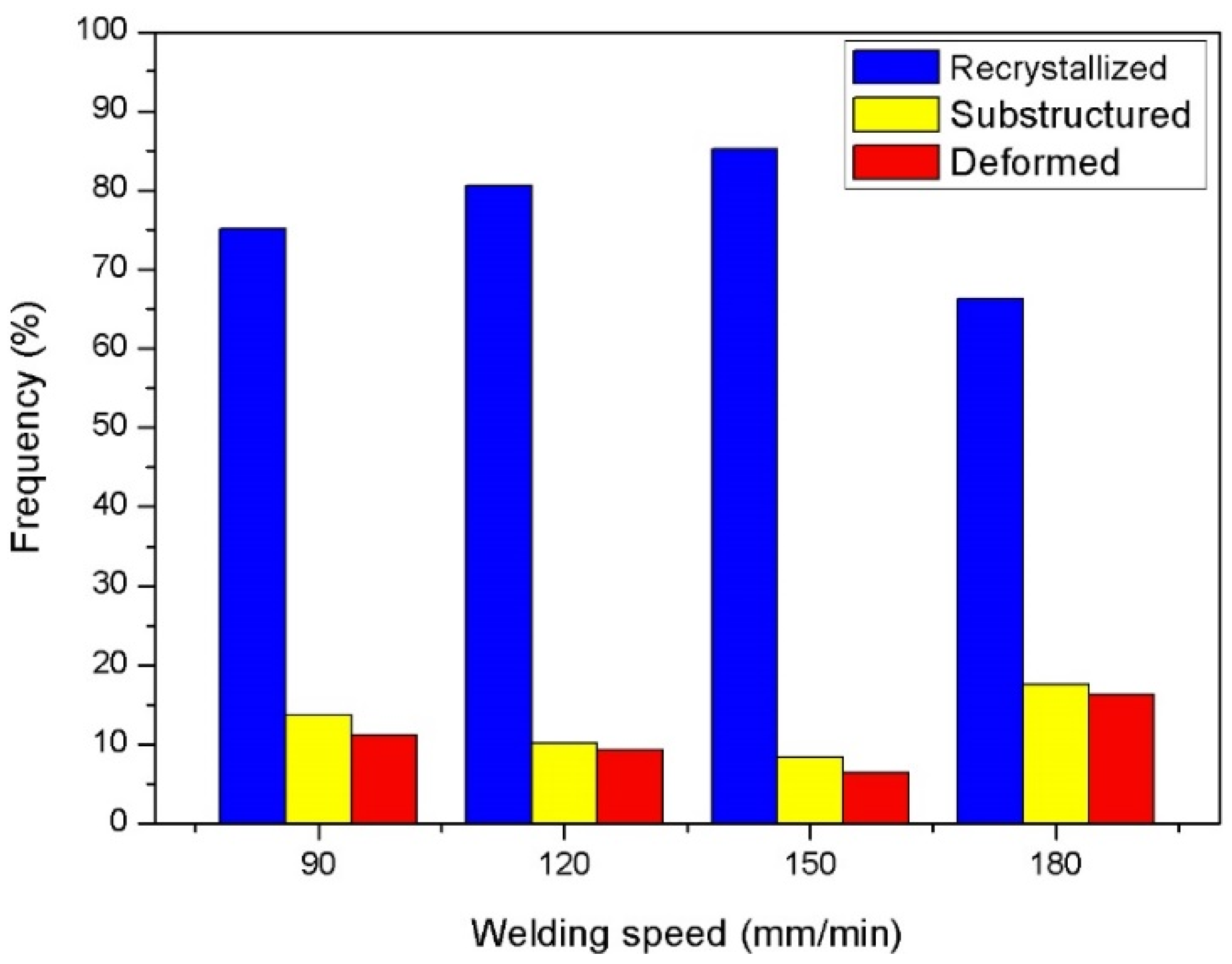
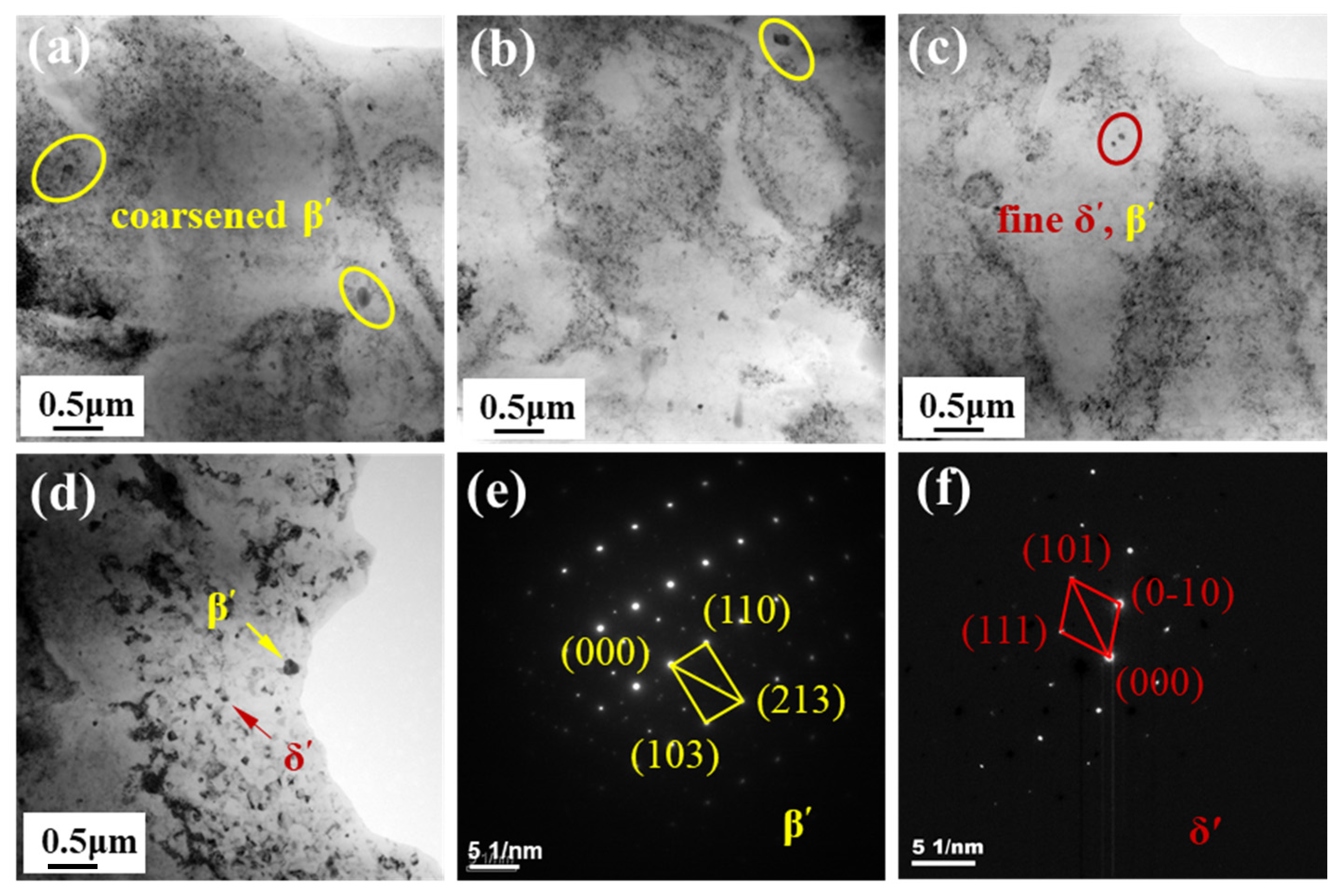
3.2. Microstructure
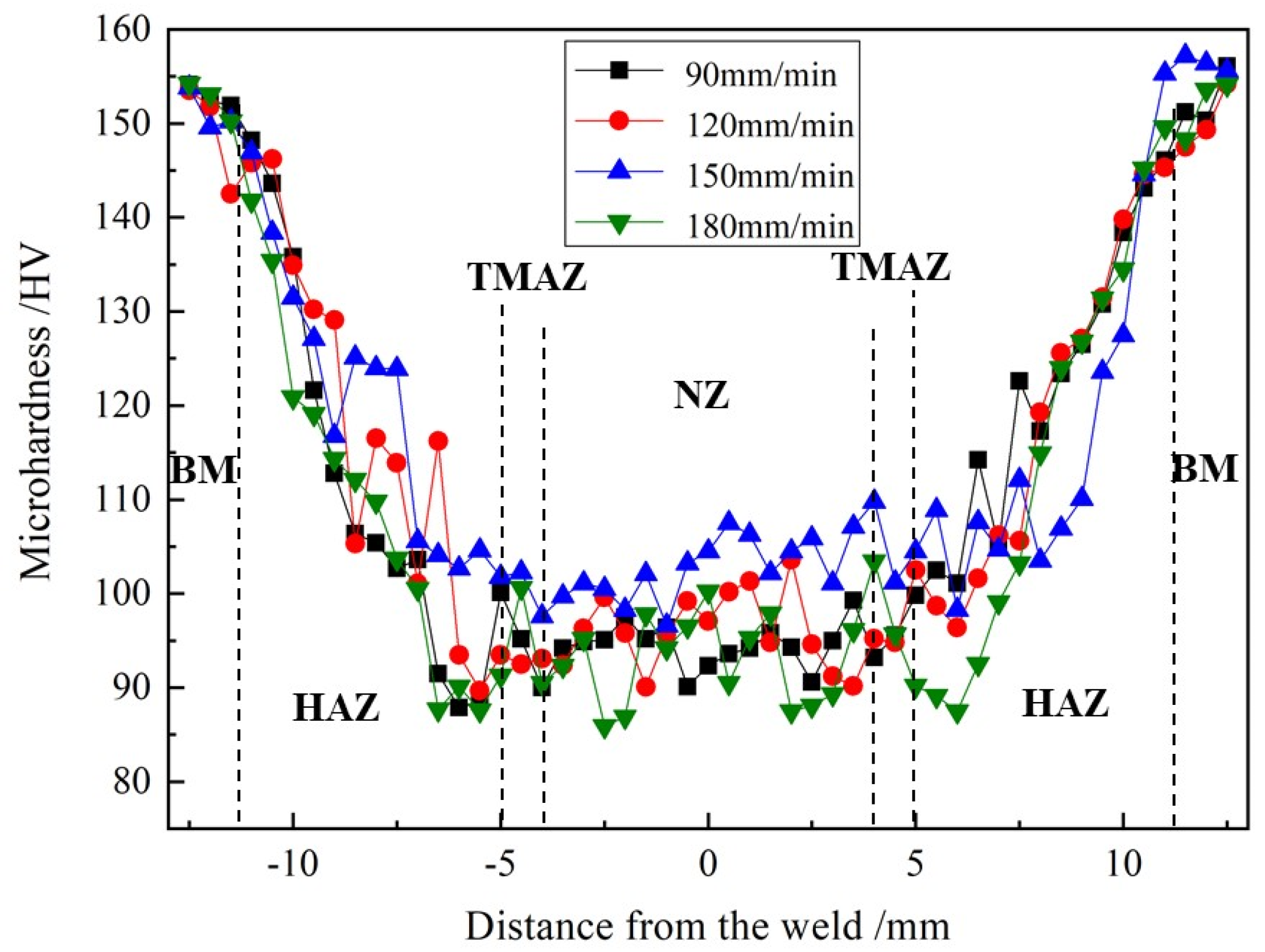
3.3. Microhardness
3.4. Mechanical Properties
3.4.1. Tensile Properties
3.4.2. Fractured Locations
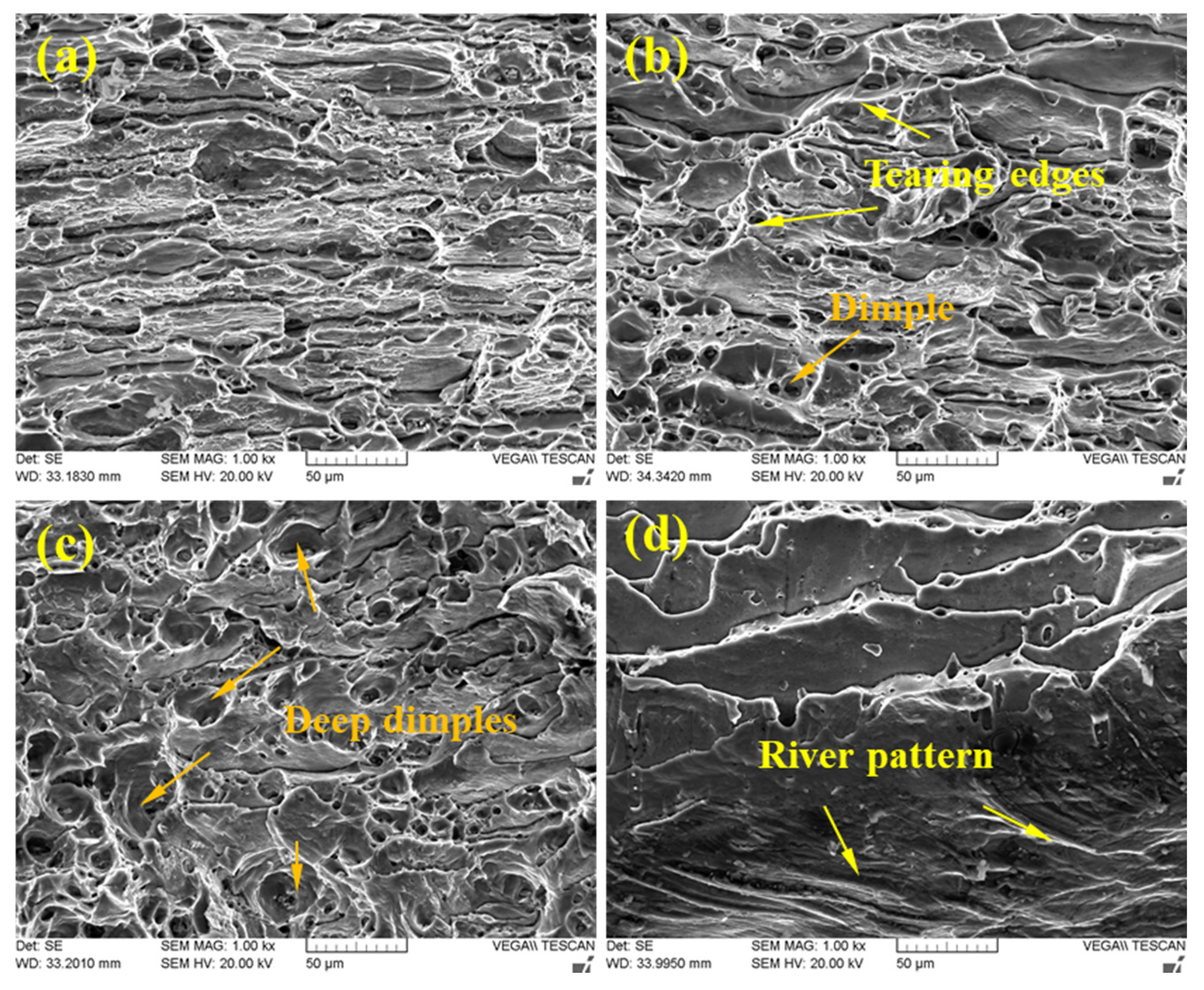
3.4.3. Fractured Surface
4. Conclusions
- With the welding speed decreasing from 180 mm/min to 90 mm/min, the size of the nugget zone (NZ) first increases and then decreases due to different welding temperatures. At 150 mm/min, the size is the biggest and the “S” curve in the NZ starts to disappear, resulting from sufficient plastic flow;
- The NZ is composed of fine equiaxed grains for all joints. Among them, the equiaxed grains are finer, attributed to a higher degree of dynamic recrystallization, when a welding speed of 150 mm/min is used. A larger number of fine reprecipitated phase (δ’, β’ phases) particles are dispersively distributed in the NZ, which can result in higher microhardness and better tensile properties of the joins;
- Compared to the base material, the average microhardness of the NZ is reduced as a greater amount of δ’ and β’ phases particles is dissolved into the NZ, which makes a more obviously negative impact recover an active contribution from finer grains;
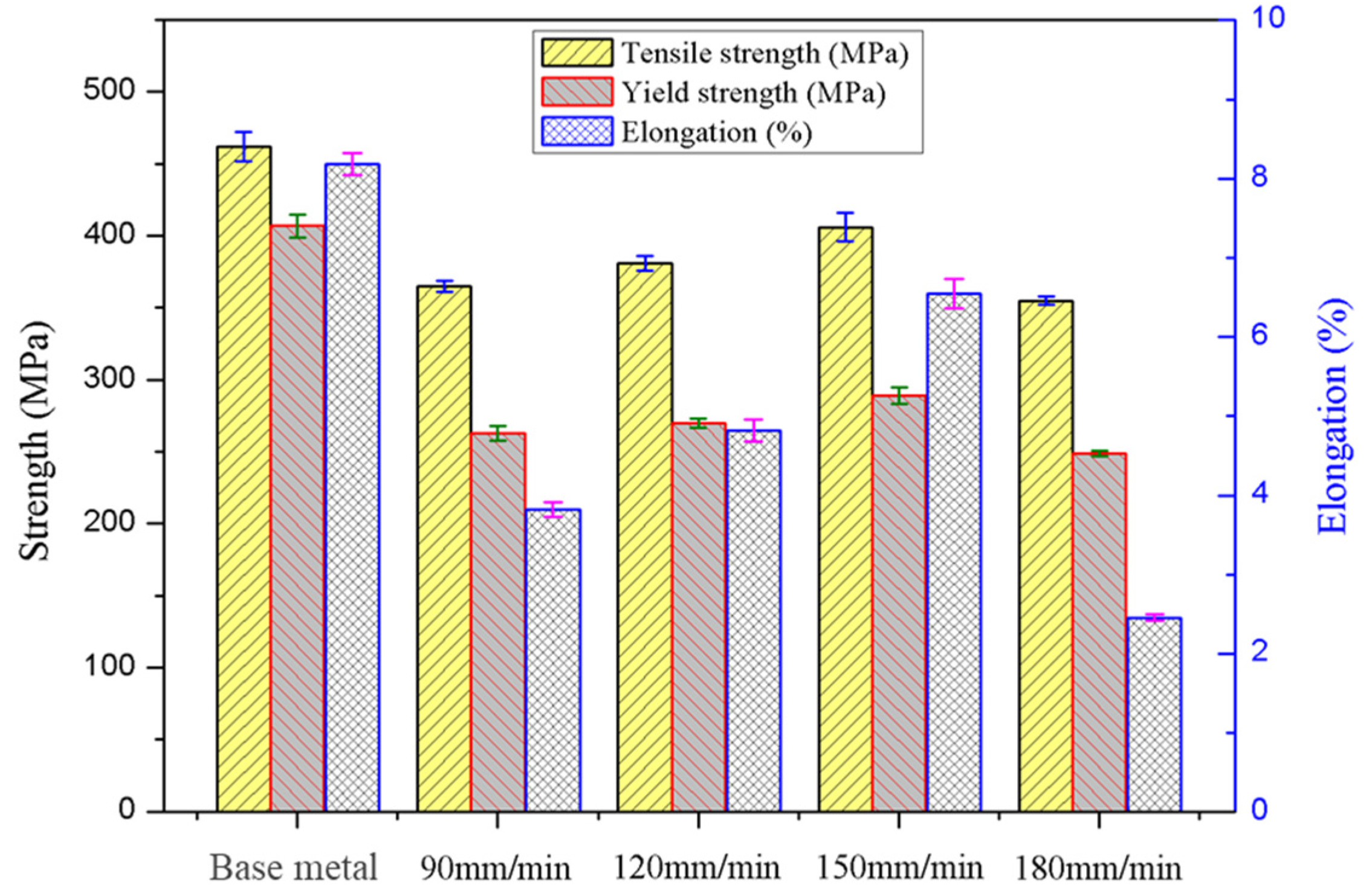
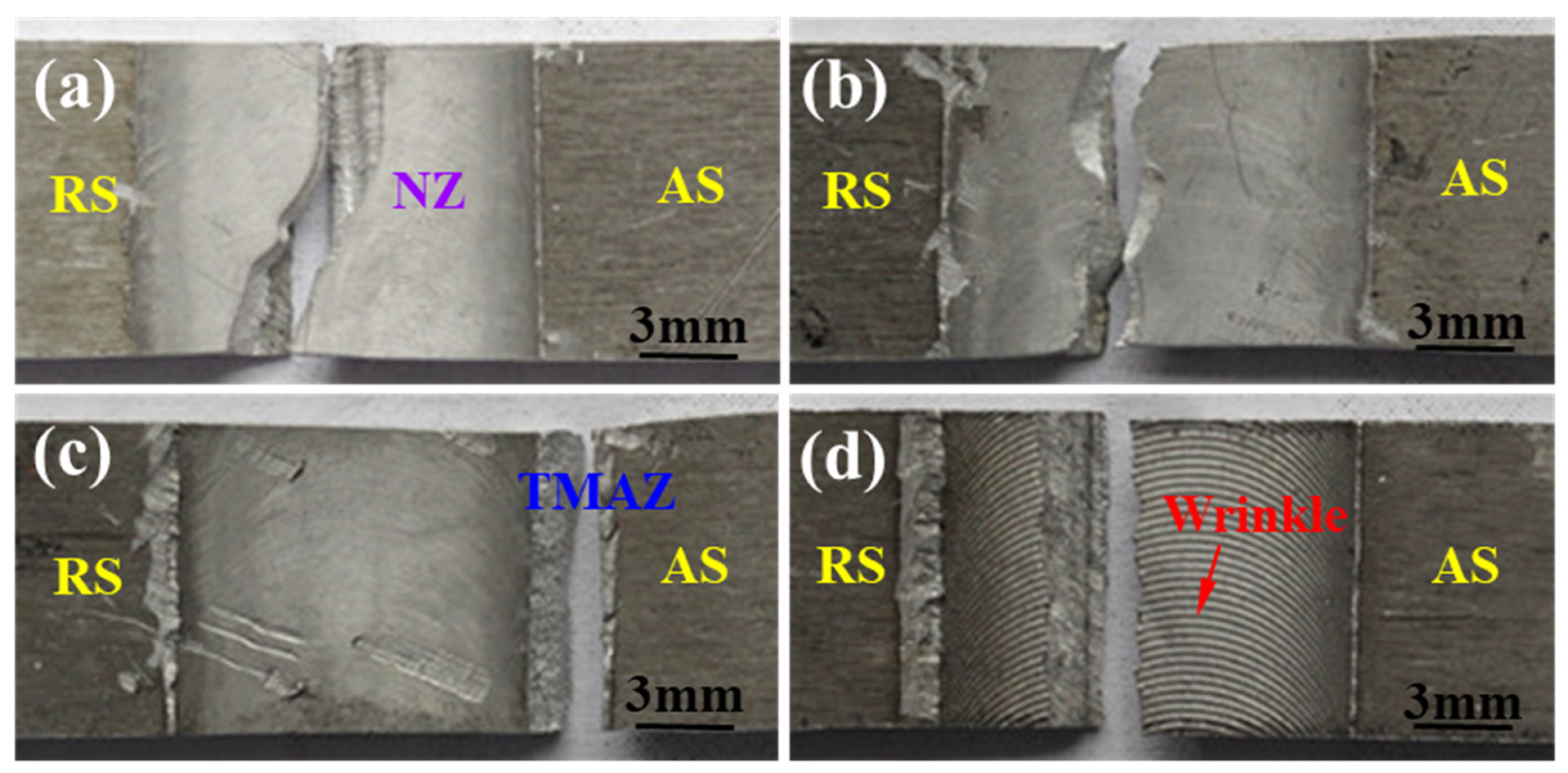
- The joints obtained at 150 mm/min have the highest tensile properties, and the tensile strength, yield strength and elongation are, respectively, 406 MPa, 289 MPa and 7.2%, which is consistent with the microstructure and microhardness of the joints. Only the joints at 150 mm/min are fractured in the TMAZ, with significant necking phenomenon. Moreover, deep dimples and many tearing ridges are detected on the fracture surface, indicating a complete ductile fracture mode.
Author Contributions
Funding
Institutional Review Board Statement
Informed Consent Statement
Data Availability Statement
Acknowledgments
Conflicts of Interest
References
- Zhao, T.; Sato, Y.S.; Xiao, R.; Huang, T.; Zhang, J. Hardness distribution and aging response associated with precipitation behavior in a laser pressure welded Al–Li alloy 2198. Mater. Sci. Eng. A 2021, 808, 140946. [Google Scholar] [CrossRef]
- Chen, Y.; Kong, F.; Yang, J.; Song, X.; Meng, X. Damage behavior of 2198-T8 Al-Li alloy with different corrosion fatigue modes. Int. J. Fatigue 2022, 156, 106671. [Google Scholar] [CrossRef]
- Le Jolu, T.; Morgeneyer, T.F.; Denquin, A.; Sennour, M.; Laurent, A.; Besson, J.; Gourgues-Lorenzon, A.F. Microstructural characterization of internal welding defects and their effect on the tensile behavior of FSW joints of AA2198 Al-Cu-Li alloy. Metall. Mater. Trans. A 2014, 45A, 5531–5544. [Google Scholar] [CrossRef]
- Wang, D.; Wu, C.; Suo, Y.; Wang, L.; Liang, Z. Effect of pulse frequency on arc behavior and droplet transfer of 2198 Al–Li alloy by ultrahigh-frequency pulse AC CMT welding. J. Mater. Res. Technol. 2019, 8, 3950–3958. [Google Scholar] [CrossRef]
- Abd El-Aty, A.; Xu, Y.; Guo, X.; Zhang, S.H.; Ma, Y.; Chen, D. Strengthening mechanisms, deformation behavior, and anisotropic mechanical properties of Al-Li alloys: A review. J. Adv. Res. 2018, 10, 49–67. [Google Scholar] [CrossRef]
- Steuwer, A.; Dumont, M.; Altenkirch, J.; Birosca, S.; Deschamps, A.; Prangnell, P.B.; Withers, P.J. A combined approach to microstructure mapping of an Al-Li AA2199 friction stirweld. Acta Mater. 2011, 59, 3002–3011. [Google Scholar] [CrossRef]
- Kim, J.H.; Jeun, J.H.; Chun, H.J.; Lee, Y.R.; Yoo, J.T.; Yoon, J.H.; Lee, H.S. Effect of precipitates on mechanical properties of AA2195. J. Alloys Compd. 2016, 669, 187–198. [Google Scholar] [CrossRef]
- Rioja, R.J.; Liu, J. The evolution of Al-Li base products for aerospace and space applications. Metall. Mater. Trans. A 2012, 43, 3325–3337. [Google Scholar] [CrossRef]
- Gao, C.; Ma, Y.; Tang, L.-Z.; Wang, P.; Zhang, X. Microstructural evolution and mechanical behavior of friction spot welded 2198-T8 Al-Li alloy during aging treatment. Mater. Des. 2017, 115, 224–230. [Google Scholar] [CrossRef]
- Yan, J.; Gao, M.; Li, G.; Zhang, C.; Zeng, X.; Jiang, M. Microstructure and mechanical properties of laser-MIG hybrid welding of 1420 Al-Li alloy. Int. J. Adv. Manuf. Technol. 2013, 66, 1467–1473. [Google Scholar] [CrossRef]
- Zhang, X.; Yang, W.; Xiao, R. Microstructure and mechanical properties of laser beam welded Al-Li alloy 2060 with Al-Mg filler wire. Mater. Des. 2015, 88, 446–450. [Google Scholar] [CrossRef]
- Huang, Y.; Meng, X.; Xie, Y.; Wan, L.; Lv, Z.; Cao, J.; Feng, J. Friction stir welding/processing of polymers and polymer matrix composites. Compos. Part A Appl. Sci. Manuf. 2018, 105, 235–257. [Google Scholar] [CrossRef]
- El Rayes, M.M.; Soliman, M.S.; Abbas, A.T.; Pimenov, D.Y.; Erdakov, I.N.; Abdel-mawla, M.M. Effect of Feed Rate in FSW on the Mechanical and Microstructural Properties of AA5754 Joints. Adv. Mater. Sci. Eng. 2019, 2019, 1–12. [Google Scholar] [CrossRef] [Green Version]
- Sidhar, H.; Martinez, N.Y.; Mishra, R.S.; Silvanus, J. Friction stir welding of Al-Mg-Li 1424 alloy. Mater. Des. 2016, 106, 146–152. [Google Scholar] [CrossRef]
- Ma, J.; Yan, D.S.; Rong, L.J. Study on the postheat treatment process and the friction-stir welding of 1460 alloy. Ordnance Mater. Sci. Eng. 2020, 43, 96–100. (In Chinese) [Google Scholar]
- Liu, H.; Hu, Y.; Dou, C.; Sekulic, D.P. An effect of the rotation speed on microstructure and mechanical properties of the friction stir welded 2060-T8 Al-Li alloy. Mater. Charact. 2017, 123, 9–19. [Google Scholar] [CrossRef]
- Chen, X.R.; Zheng, Z.Q.; Ye, Z.H.; Kong, X. Microstructure characterization of friction stir welded 2099 Al-Li alloy. Rare Met. Mater. Eng. 2018, 47, 97–100. [Google Scholar]
- Zhang, J.; Feng, X.S.; Gao, J.S.; Huang, H.; Ma, Z.Q.; Guo, L.J. Effects of welding parameters and postheat treatment on mechanical properties of friction stir welded AA2195-T8 Al-Li alloy. J. Mater. Sci. Technol. 2018, 34, 219–227. [Google Scholar] [CrossRef]
- Mao, Y.; Ke, L.; Liu, F.; Huang, C.; Chen, Y.; Liu, Q. Effect of welding parameters on microstructure and mechanical proper-ties of friction stir welded joints of 2060 aluminum lithium alloy. Int. J. Adv. Manuf. Technol. 2015, 81, 1419–1431. [Google Scholar] [CrossRef]
- Xing, L.; Song, X.; Ke, L.M. Microstructures and me-chanical properties of friction stir welding dissimilar 2198 and C24S Al-Li alloys. Chin. J. Nonferrous Met. 2014, 24, 1714–1720. (In Chinese) [Google Scholar]
- Zoeram, A.S.; Anijdan, S.M.; Jafarian, H.R.; Bhattacharjee, T. Welding parameters analysis and microstructural evolution of dissimilar joints in Al/Bronze processed by friction stir welding and their effect on engineering tensile behavior. Mater. Sci. Eng. A 2017, 687, 288–297. [Google Scholar] [CrossRef]
- Colegrove, P.A.; Sherclif, H.R. Development of Trivex friction stir welding tool, Part 1—Two dimensional flow modeling and experimental validation. Sci. Technol. Weld. Join. 2004, 9, 345–352. [Google Scholar] [CrossRef]
- Schmidt, H.; Hattel, J. A local model for the thermomechanical conditions in friction stir welding. Model. Simul. Mater. Sci. Eng. 2005, 13, 77–93. [Google Scholar] [CrossRef]
- Cai, B.; Zheng, Z.; He, D. Friction stir weld of 2060 Al-Cu-Li alloy: Microstructure and mechanical properties. J. Alloys Compd. 2015, 649, 19–27. [Google Scholar] [CrossRef]
- Qin, H.; Zhang, H.; Wu, H. The evolution of precipitation and microstructure in friction stir welded 2195-T8 Al-Li alloy. Mater. Sci. Eng. A 2015, 626, 322–329. [Google Scholar] [CrossRef]
- Schneider, J.; Nunes, A.; Chen, P. TEM study of the FSW nugget in AA2195-T81. J. Mater. Sci. 2005, 40, 4341–4345. [Google Scholar] [CrossRef]
- Mao, Y.-Q.; Yang, P.; Ke, L.-M.; Xu, Y.; Chen, Y.-H. Microstructure Evolution and Recrystallization Behavior of Friction Stir Welded Thick Al-Mg-Zn-Cu alloys: Influence of Pin Centerline Deviation. Acta Metall. Sin. (Engl. Lett.) 2021. [Google Scholar] [CrossRef]
- Wang, L.; Wang, H.M.; Ma, F.Y.; Wang, F.F.; Meng, Z.X. Microstructure and properties of 2195 Al-Li alloy welded joints by friction stir welding. Weld. Join. 2019, 3, 24–27. [Google Scholar]
- Sato, Y.S.; Urata, M.; Kokawa, H.; Ikeda, K. Hall-Petch relationship in friction stir welds of equal channel angular-pressed aluminium alloys. Mater. Sci. Eng. A 2003, 354, 298–305. [Google Scholar] [CrossRef]
- Shukla, A.K.; Baeslack, W.A. Study of microstructural evolution in friction-stir welded thin-sheet Al-Cu-Li alloy using transmission electron microscopy. Scr. Mater. 2007, 56, 513–516. [Google Scholar] [CrossRef]
- Li, W.; Jiang, R.; Zhang, Z.; Ma, Y. Effect of rotation speed to welding speed ratio on microstructure and mechanical behavior of friction stir welded aluminum-lithium alloy joints. Adv. Eng. Mater. 2013, 15, 1051–1058. [Google Scholar] [CrossRef]


| Alloy | Mass Fracture (%) | |||||
|---|---|---|---|---|---|---|
| Cu | Li | Mg | Mn | Zr | Al | |
| 2198-T8 | 2.9–3.5 | 0.8–1.1 | 0.25–0.8 | 0.1–0.5 | 0.04–0.18 | Bal |
Publisher’s Note: MDPI stays neutral with regard to jurisdictional claims in published maps and institutional affiliations. |
© 2022 by the authors. Licensee MDPI, Basel, Switzerland. This article is an open access article distributed under the terms and conditions of the Creative Commons Attribution (CC BY) license (https://creativecommons.org/licenses/by/4.0/).
Share and Cite
Zhang, W.; Mao, Y.; Yang, P.; Li, N.; Ke, L.; Chen, Y. Effect of Welding Speed on Microstructure Evolution and Mechanical Properties of Friction Stir Welded 2198 Al-Cu-Li Alloy Joints. Materials 2022, 15, 969. https://doi.org/10.3390/ma15030969
Zhang W, Mao Y, Yang P, Li N, Ke L, Chen Y. Effect of Welding Speed on Microstructure Evolution and Mechanical Properties of Friction Stir Welded 2198 Al-Cu-Li Alloy Joints. Materials. 2022; 15(3):969. https://doi.org/10.3390/ma15030969
Chicago/Turabian StyleZhang, Wenyan, Yuqing Mao, Ping Yang, Ning Li, Liming Ke, and Yu Chen. 2022. "Effect of Welding Speed on Microstructure Evolution and Mechanical Properties of Friction Stir Welded 2198 Al-Cu-Li Alloy Joints" Materials 15, no. 3: 969. https://doi.org/10.3390/ma15030969
APA StyleZhang, W., Mao, Y., Yang, P., Li, N., Ke, L., & Chen, Y. (2022). Effect of Welding Speed on Microstructure Evolution and Mechanical Properties of Friction Stir Welded 2198 Al-Cu-Li Alloy Joints. Materials, 15(3), 969. https://doi.org/10.3390/ma15030969