
Effect of High-Current Pulsed Electron Beam on Properties of Graphene-Modified Aluminum Titanium Carbide Composites

 ,
, 
Abstract
1. Introduction
2. Experimental Procedure
2.1. Preparation of Materials
2.2. HCPEB Treatment
2.3. Microstructure Characterisation and Performance Analysis
3. Results and Discussion
4. Conclusions
- (1)
- The XRD results showed that no new phases were generated on the surface of the aluminum matrix composites after the electron beam treatment, and the relative intensities of the diffraction peaks changed, which may be due to the selective orientation and the change of the weave coefficients after the HCPEB treatment.
- (2)
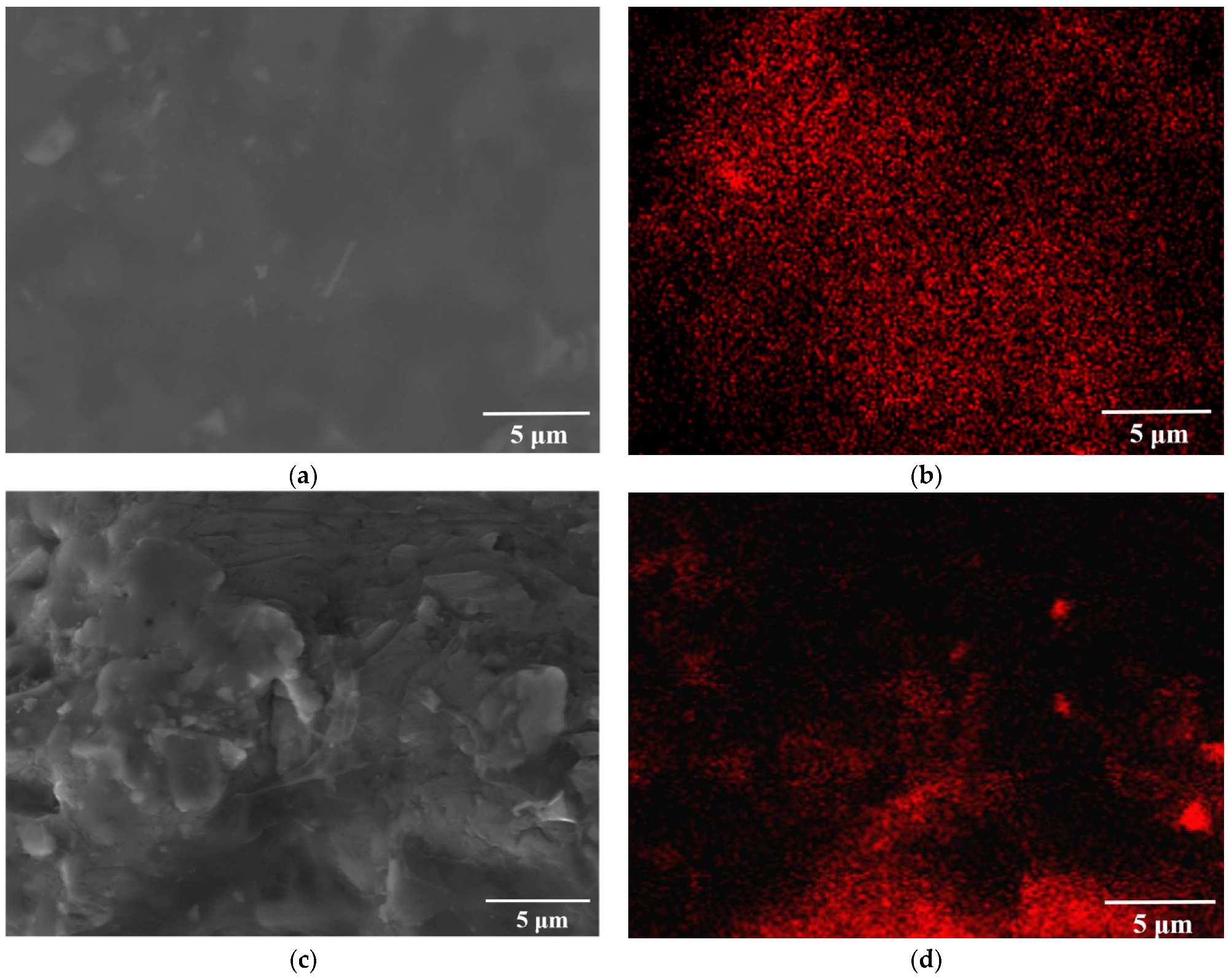
- The scanning electron microscopy results show that the addition of graphene makes the TiC particles more uniformly distributed in the aluminum matrix, and the composite has a good surface without obvious metallurgical defects. Meanwhile, the rapid melting and solidification effect of the electron beam makes the molten aluminum fill and reduce the pores.
- (3)
- The conductivity test results showed that the addition of graphene to the aluminum matrix substantially improved the conductivity of the aluminum matrix by 94.3%.
- (4)
- The microhardness test results showed that, compared with the initial Al-20TiC composite samples, the microhardness of graphene-modified HCPEB-treated sample increased by 18.4%.
- (5)
- The results of the wear resistance test show that the friction coefficient of the sample surface reached the minimum value at 25 pulses from 0.794 in the initial sample to 0.585 in the 25-pulse-treated Al-20TiC-0.3G composites.
Author Contributions
Funding
Institutional Review Board Statement
Informed Consent Statement
Data Availability Statement
Acknowledgments
Conflicts of Interest
References
- Sun, Z.; Zhang, D.; Li, G. Evaluation of dry sliding wear behavior of silicon particles reinforced aluminum matrix composites. Mater. Des. 2005, 26, 454–458. [Google Scholar]
- Karamis, M.B.; Nair, F. Effects of reinforcement particle size in MMCs on extrusion die wear. Wear 2008, 265, 1741–1750. [Google Scholar] [CrossRef]
- Liu, Y.; Chen, G.; Zhang, H.; Yang, C.; Zhang, S.; Liu, Q.; Zhou, M.; Shi, Q. In situ exfoliation of graphite for fabrication of graphene/aluminum composites by friction stir processing. Mater. Lett. 2021, 301, 130280. [Google Scholar] [CrossRef]
- Zhang, S.; Chen, G.; Qu, T.; Fang, G.; Bai, S.; Yan, Y.; Zhang, G.; Zhou, Z.; Shen, J.; Yao, D.; et al. Simultaneously enhancing mechanical properties and electrical conductivity of aluminum by using graphene as the reinforcement. Mater. Lett. 2020, 265, 127440. [Google Scholar] [CrossRef]
- Pérez-Bustamante, R.; Bolaños-Morales, D.; Bonilla-Martínez, J.; Estrada-Guel, I.; Martínez-Sánchez, R. Microstructural and hardness behavior of gra-phene-nanoplatelets/aluminum composites synthesized by mechanical alloying. J. Alloys Compd. 2014, 615, S578–S582. [Google Scholar] [CrossRef]
- Asgharzadeh, H.; Sedigh, M. Synthesis and mechanical properties of Al matrix composites reinforced with few-layer graphene and graphene oxide. J. Alloys Compd. 2017, 728, 47–62. [Google Scholar] [CrossRef]
- Arunachalam, R.; Krishnan, P.K.; Muraliraja, R. A review on the production of metal matrix composites through stir casting-Furnace design, properties, challenges, and research opportunities. J. Manuf. Process. 2019, 42, 213–245. [Google Scholar]
- Yang, J.Y.; Chung, D.L. Casting particulate and fibrous metal-matrix composites by vacuum infiltration of a liquid metal under inert gas pressure. J. Mater. Sci. 1989, 24, 3605–3612. [Google Scholar] [CrossRef]
- Torrabla, J.M.; Da Costa, C.E.; Velasco, F. P/M aluminum matrix composites: An overview. J. Mater. Process. Technol. 2003, 133, 203–206. [Google Scholar]
- Rashad, M.; Pan, F.; Yu, Z.; Asif, M.; Lin, H.; Pan, R. Investigation on microstructural, mechanical and electrochemical properties of aluminum composites reinforced with graphene nanoplatelets. Prog. Nat. Sci. 2015, 25, 460–470. [Google Scholar] [CrossRef]
- Yan, P.; Zou, J.; Zhang, C.; Grosdidier, T. Surface modifications of a cold rolled 2024 Al alloy by high current pulsed electron beams. Appl. Surf. Sci. 2019, 504, 144382. [Google Scholar] [CrossRef]
- Guo, F.; Jiang, W.; Tang, G.; Xie, Z.; Dai, H.; Wang, E.; Chen, Y.; Liu, L. Enhancing anti-wear and anti-corrosion performance of cold spraying aluminum coating by high current pulsed electron beam irradiation. Vacuum 2020, 182, 109772. [Google Scholar] [CrossRef]
- Sun, Y.; Li, K.; Gao, B.; Sun, P.; Fu, H.; Liu, Z.; Yin, J. Study on microstructure and wear resistance of Zr-17Nb alloy irradiated by high current pulsed electron beam. Rev. Adv. Mater. Sci. 2020, 59, 514–522. [Google Scholar] [CrossRef]
- Zou, J.X.; Grosdidier, T.; Zhang, K.; Dong, C. Mechanisms of nanostructure and metastable phase formations in the surface melted layers of a HCPEB-treated D2 steel. Acta Mater. 2006, 54, 5409–5419. [Google Scholar] [CrossRef]
- Hao, S.; Wu, P.; Zou, J.; Grosdidier, T.; Dong, C. Microstructure evolution occurring in the modifified surface of 316L stainless steel under high current pulsed electron beam treatment. Appl. Surf. Sci. 2007, 253, 5349–5354. [Google Scholar] [CrossRef]
- Hao, Y.; Gao, B.; Tu, G.F.; Cao, H.; Hao, S.Z.; Dong, C. Surface modification of Al-12.6Si alloy by high current pulsed electron beam. Appl. Surf. Sci. 2012, 258, 2052–2056. [Google Scholar] [CrossRef]
- Dong, S.; Zhang, C.; Zhang, L.; Cai, J.; Lv, P.; Jin, Y.; Guan, Q. Microstructure and properties of Cu-Cr powder metallurgical alloy induced by high-current pulsed electron beam. J. Alloys Compd. 2018, 755, 251–256. [Google Scholar] [CrossRef]
- Zhang, C.; Li, L.; Jiang, Q.; Ma, C.; Yang, Z.; Jin, Y.; Guan, Q. The impact of high current pulses electron beam on the microstructure and surface properties of Sn/Al system. J. Alloys Compd. 2020, 861, 157980. [Google Scholar] [CrossRef]
- Gao, B.; Li, K.; Xing, P.F. Formation of a double-layer ultrafifine crystal structure for high-current pulsed electron beam-treated Al-20Si-5Mg alloy. Coatings 2019, 9, 413. [Google Scholar] [CrossRef]
- Li, K.; Gao, B.; Xu, N.; Sun, Y.; Denisov, V.V.; Hu, L. The Influence of Neodymium Element on the Crater Structure Formed on Al-17.5Si Alloy Surface Processed by High-Current Pulsed Electron Beam. Coatings 2020, 10, 922. [Google Scholar] [CrossRef]
- Hu, L.; Gao, B.; Lv, J.K.; Sun, S.C.; Hao, Y.; Tu, G.F. Halo Evolution of Hypereutectic Al-17.5Si Alloy Treated with High-Current Pulsed Electron Beam. J. Nanomater. 2015, 2015, 806151. [Google Scholar] [CrossRef]
- Hao, S.; Zhang, X.; Mei, X.; Grosdidier, T.; Dong, C. Surface treatment of DZ4 directionally solidified nickel-based superalloy by high current pulsed electron beam. Mater. Lett. 2008, 62, 414–417. [Google Scholar] [CrossRef]
- Grosdidier, T.; Zou, J.X.; Stein, N.; Boulanger, C.; Hao, S.Z.; Dong, C. Texture modification, grain refinement and improved hardness/corrosion balance of a FeAl alloy by pulsed electron beam surface treatment in the “heating mode”. Scr. Mater. 2008, 58, 1058–1061. [Google Scholar] [CrossRef]
- Zou, J.; Zhang, K.; Dong, C.; Qin, Y.; Hao, S.; Grosdidier, T. Selective surface purification via crater eruption under pulsed electron beam irradiation. Appl. Phys. Lett. 2006, 89, 041913. [Google Scholar] [CrossRef]
- Sun, Y.; Gao, B.; Hu, L.; Li, K.; Zhang, Y. Effect of CeO2 on Corrosion Resistance of High-Current Pulsed Electron Beam Treated Pressureless Sintering Al-20SiC Composites. Coatings 2021, 11, 707. [Google Scholar] [CrossRef]
- Wang, J.; Guo, L.N.; Lin, W.M.; Chen, J.; Liu, C.L.; Zhang, S.; Zhen, T.T. Effect of the graphene content on the microstructures and properties of graphene/aluminum composites. New Carbon Mater. 2019, 34, 275–285. [Google Scholar] [CrossRef]
- Yu, H.; Zhang, S.Q.; Xia, J.H.; Su, Q.; Ma, B.C.; Wu, J.H.; Zhou, J.X.; Wang, X.T.; Hu, L.X. Microstructural evolution, mechanical and physical properties of graphene reinforced aluminum composites fabricated via powder metallurgy. Mater. Sci. Eng. A 2021, 802, 140669. [Google Scholar] [CrossRef]


| Powder | Purity/wt.% | Particle Size/μm |
|---|---|---|
| Al | 99.9 | 50 |
| TiC | 99.9 | 10 |
| Graphene | 97.5 | 0.001–0.003 |
Publisher’s Note: MDPI stays neutral with regard to jurisdictional claims in published maps and institutional affiliations. |
© 2022 by the authors. Licensee MDPI, Basel, Switzerland. This article is an open access article distributed under the terms and conditions of the Creative Commons Attribution (CC BY) license (https://creativecommons.org/licenses/by/4.0/).
Share and Cite
Zhang, Y.; Zhu, G.; Gao, B.; Wang, L.; Li, Z.; Hu, L.; Shi, Z.; Yin, Q. Effect of High-Current Pulsed Electron Beam on Properties of Graphene-Modified Aluminum Titanium Carbide Composites. Materials 2022, 15, 7879. https://doi.org/10.3390/ma15227879
Zhang Y, Zhu G, Gao B, Wang L, Li Z, Hu L, Shi Z, Yin Q. Effect of High-Current Pulsed Electron Beam on Properties of Graphene-Modified Aluminum Titanium Carbide Composites. Materials. 2022; 15(22):7879. https://doi.org/10.3390/ma15227879
Chicago/Turabian StyleZhang, Ying, Guanglin Zhu, Bo Gao, Lei Wang, Zongbin Li, Liang Hu, Zeyuan Shi, and Qihao Yin. 2022. "Effect of High-Current Pulsed Electron Beam on Properties of Graphene-Modified Aluminum Titanium Carbide Composites" Materials 15, no. 22: 7879. https://doi.org/10.3390/ma15227879
APA StyleZhang, Y., Zhu, G., Gao, B., Wang, L., Li, Z., Hu, L., Shi, Z., & Yin, Q. (2022). Effect of High-Current Pulsed Electron Beam on Properties of Graphene-Modified Aluminum Titanium Carbide Composites. Materials, 15(22), 7879. https://doi.org/10.3390/ma15227879