
Bending Behaviour of Prestressed T-Shaped Concrete Beams Reinforced with FRP—Experimental and Analytical Investigations


Abstract
:
1. Introduction
2. Materials
2.1. Concrete
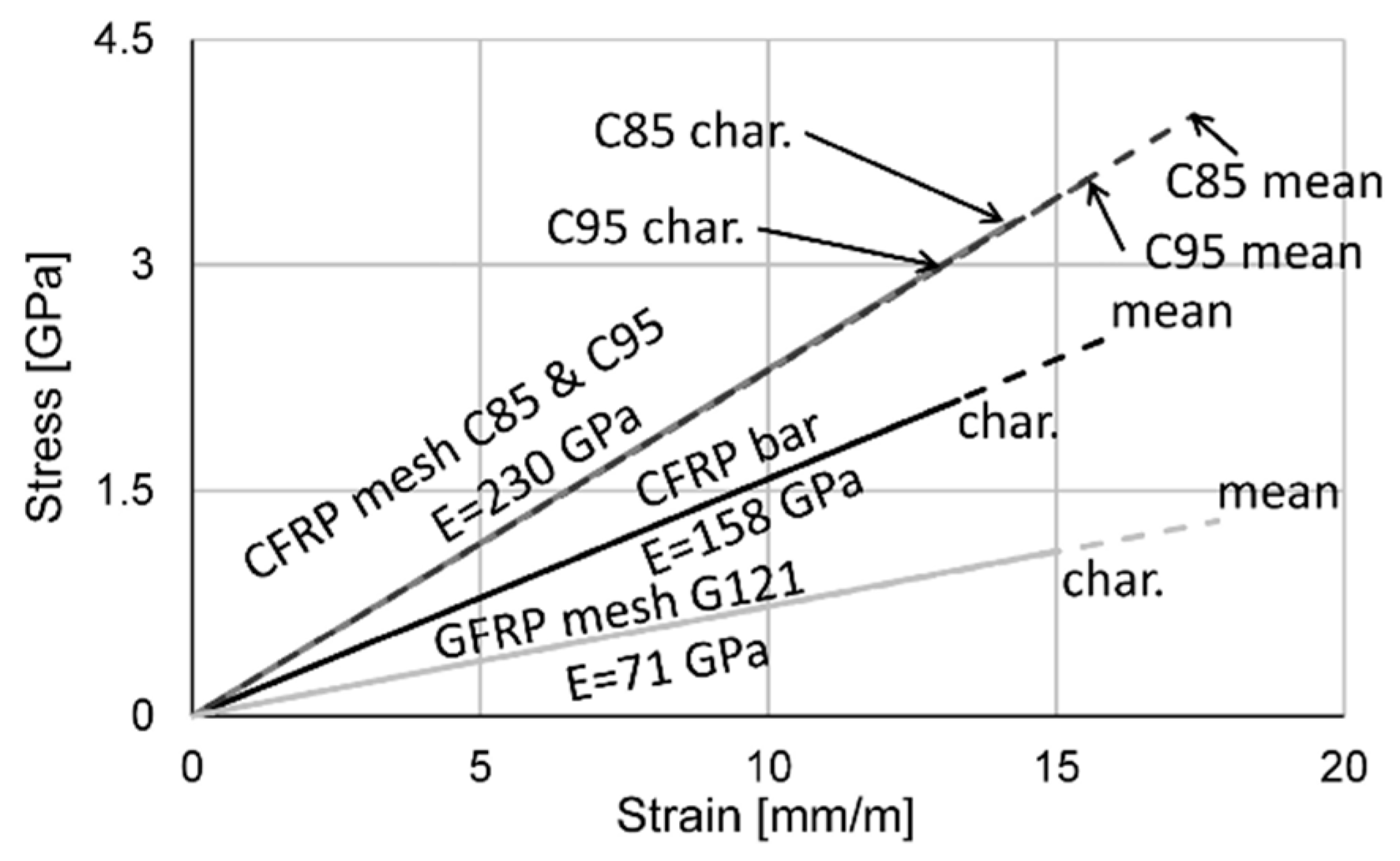
2.2. Fibre-Reinforced Polymers
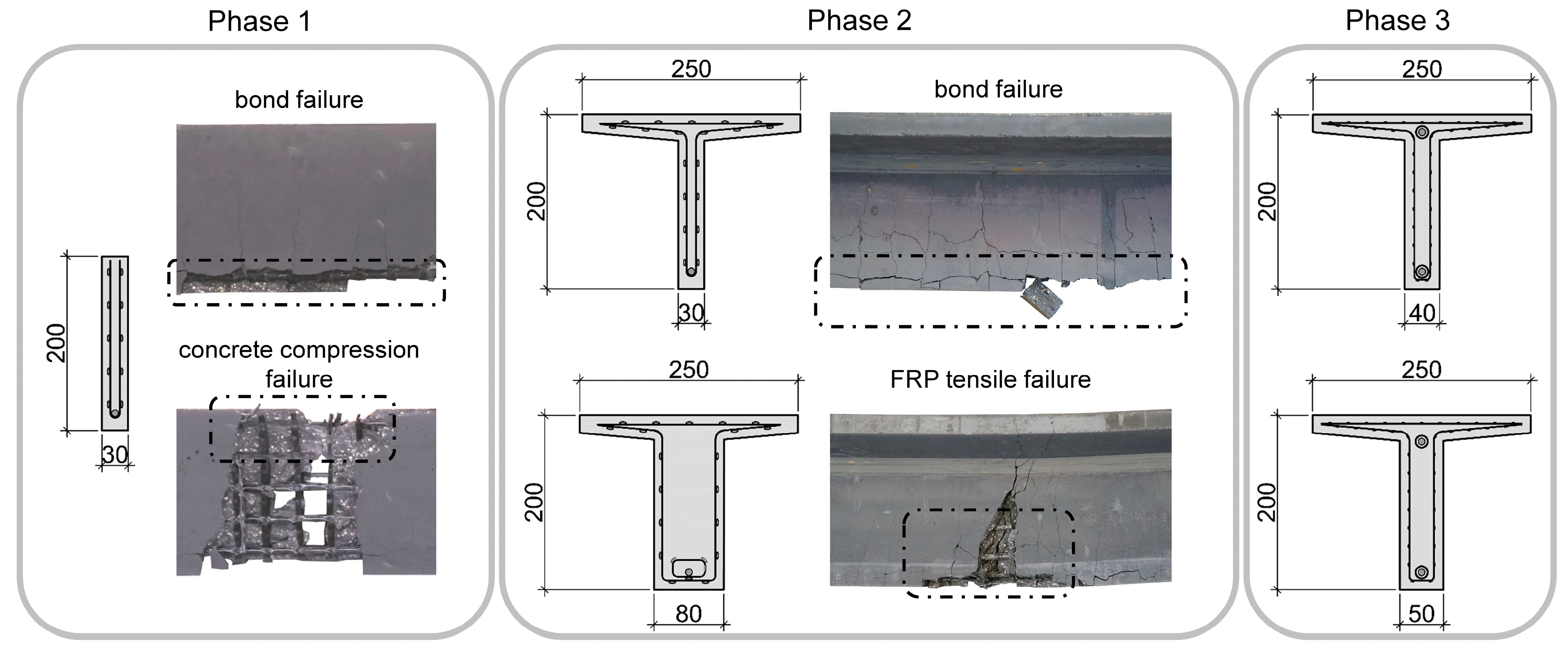
3. Preliminary Investigations
4. Experimental Investigations
4.1. Testing Configurations
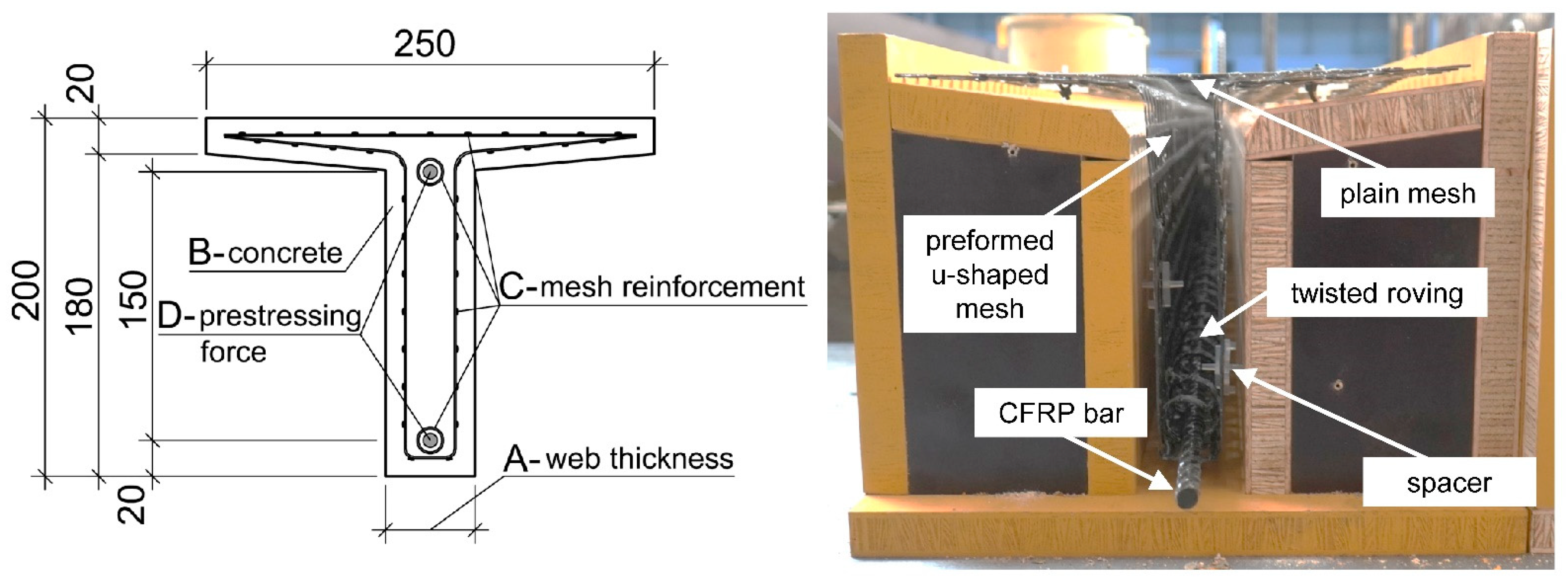
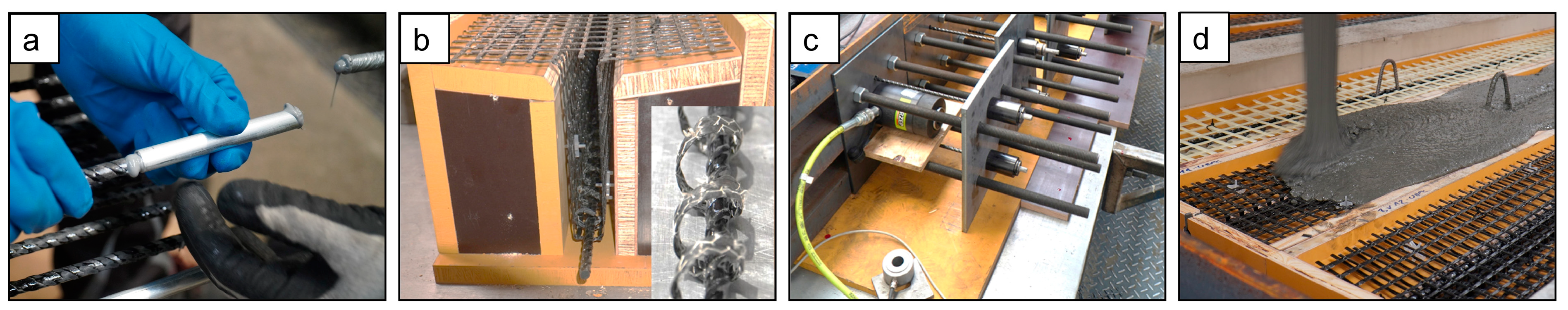
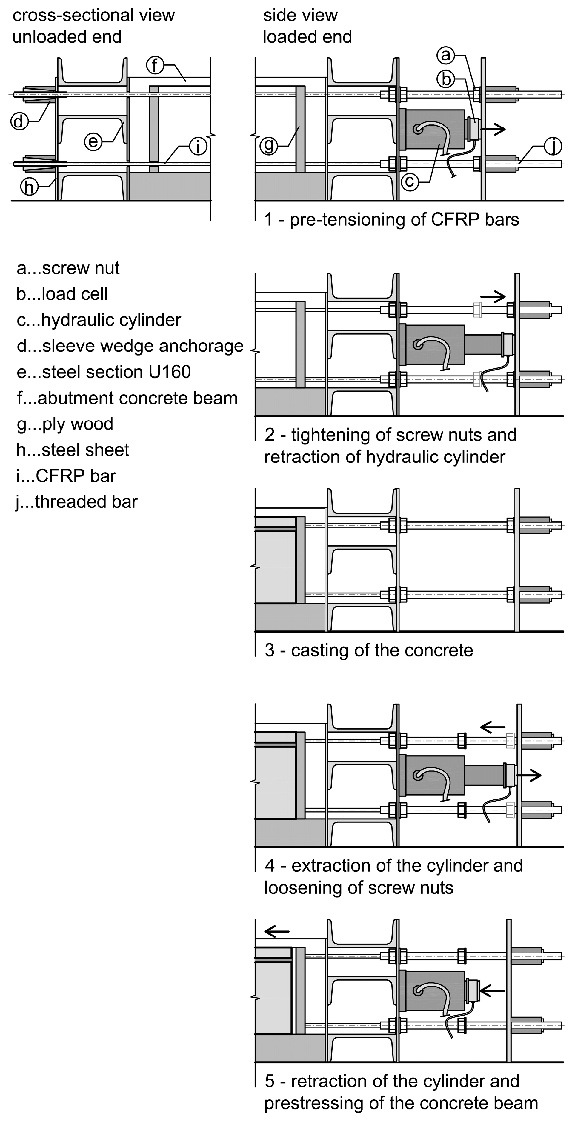
4.2. Specimen Preparation and Prestressing
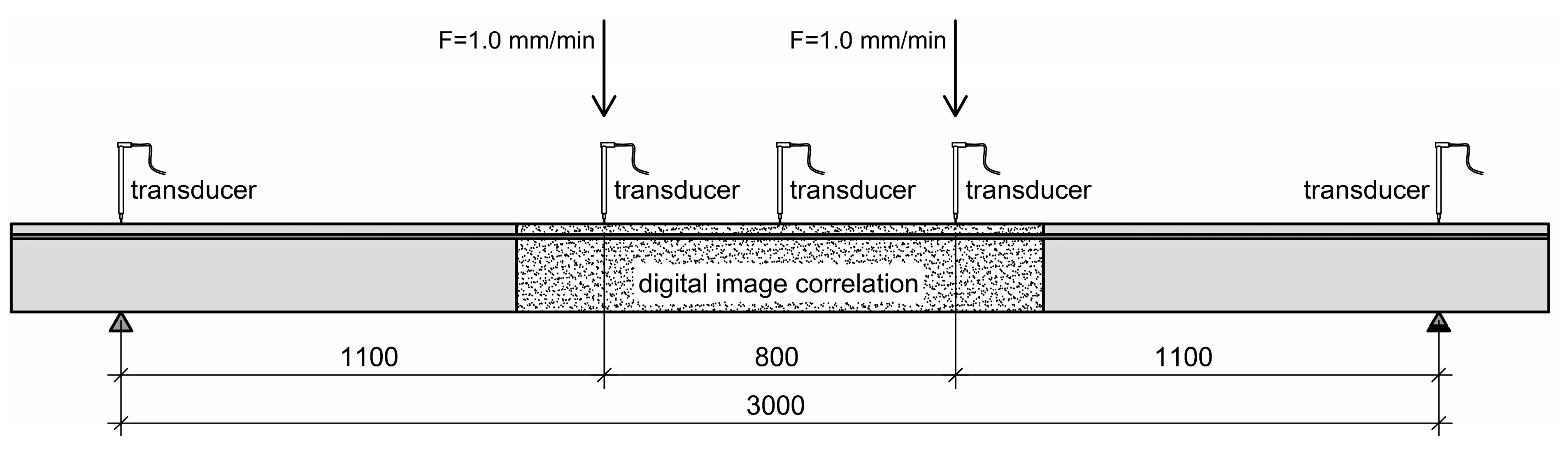
4.3. Test Setup
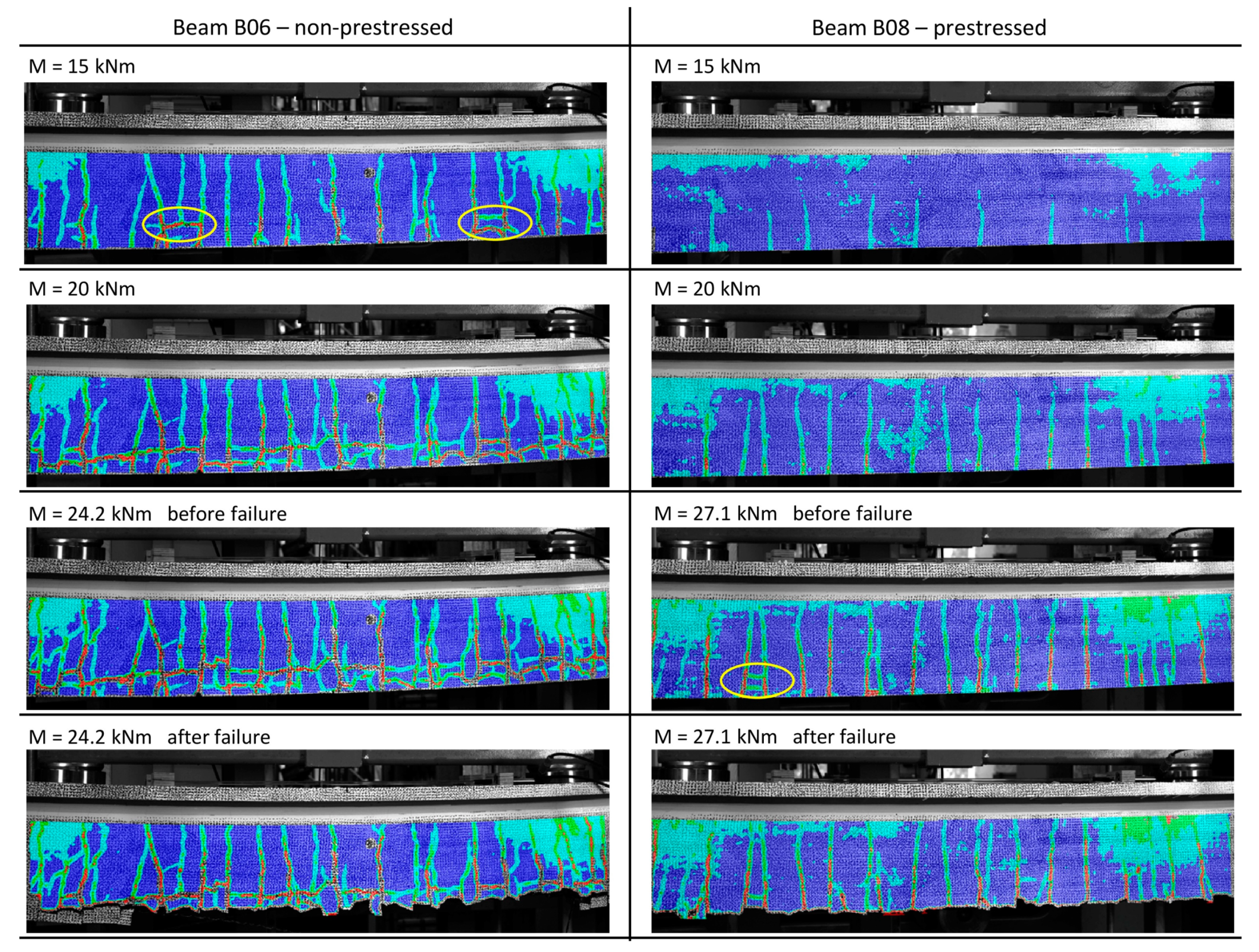
4.4. Results
5. Analytical Investigations
- Definition of the geometry of the different configurations using points for the centre of the reinforcement, and points and lines for the cross section.
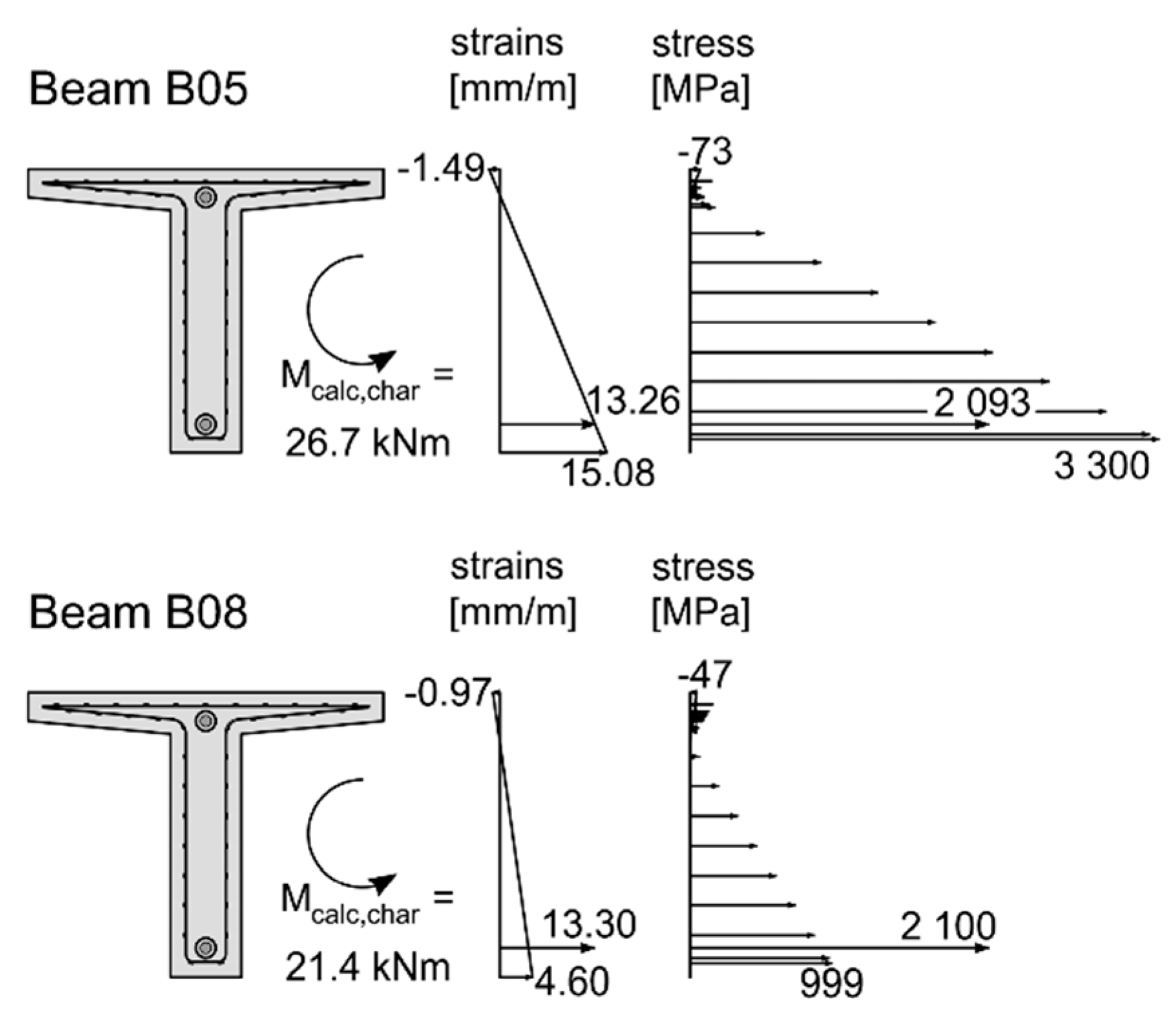
- Recalculation of every beam, further referred to as beam B01_char and B01_mean using the characteristic or mean material properties of the reinforcement (Table 3) for the nonlinear analysis.
- Loading the cross section with the pre-tensioning force with an initial strain in the CFRP bars. Based on the characteristic breaking strain of 13.3 mm/m, the strain for prestressing was calculated with 3.99 mm/m (30%), 6.65 mm/m (50%) and 9.31 mm/m (70%).
6. Conclusions
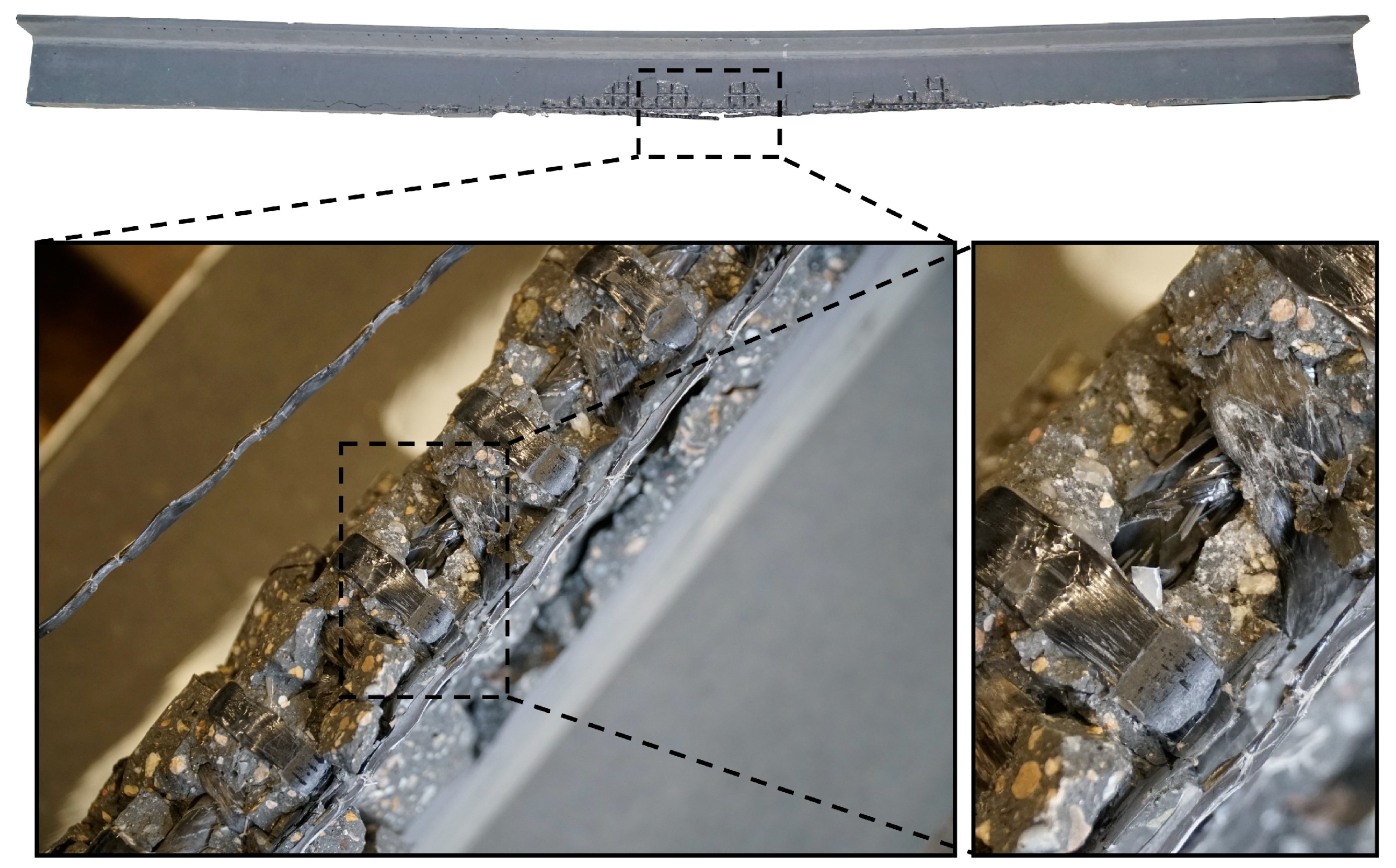
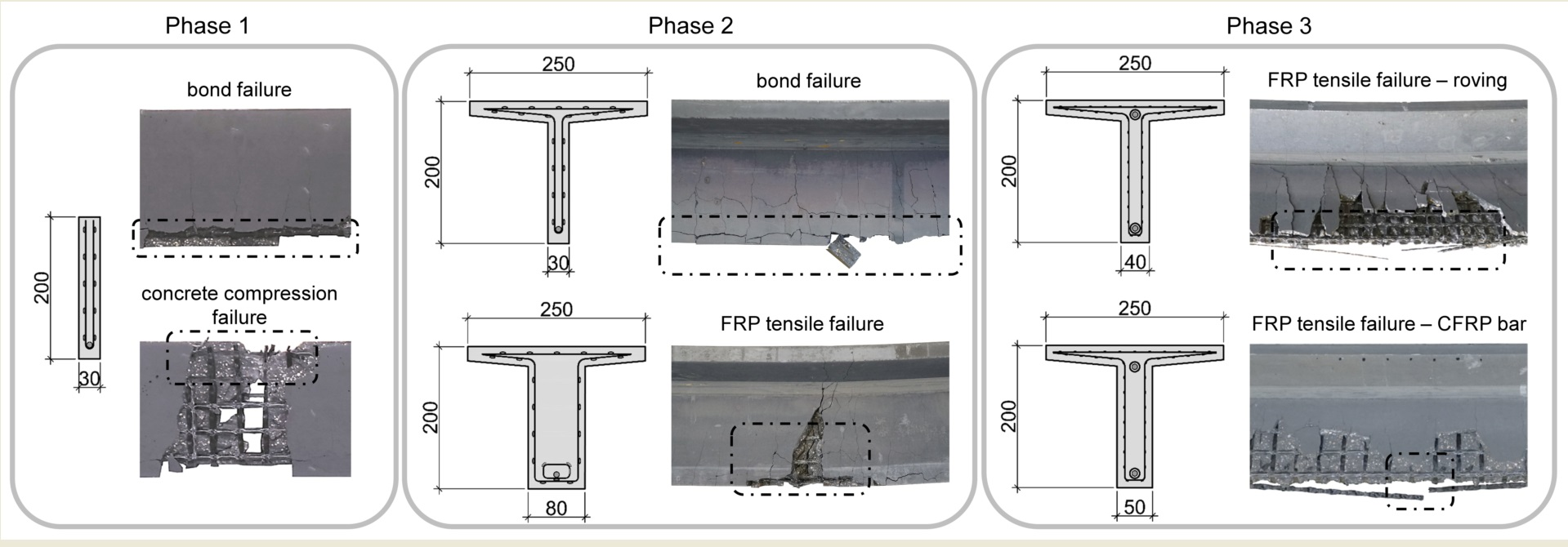
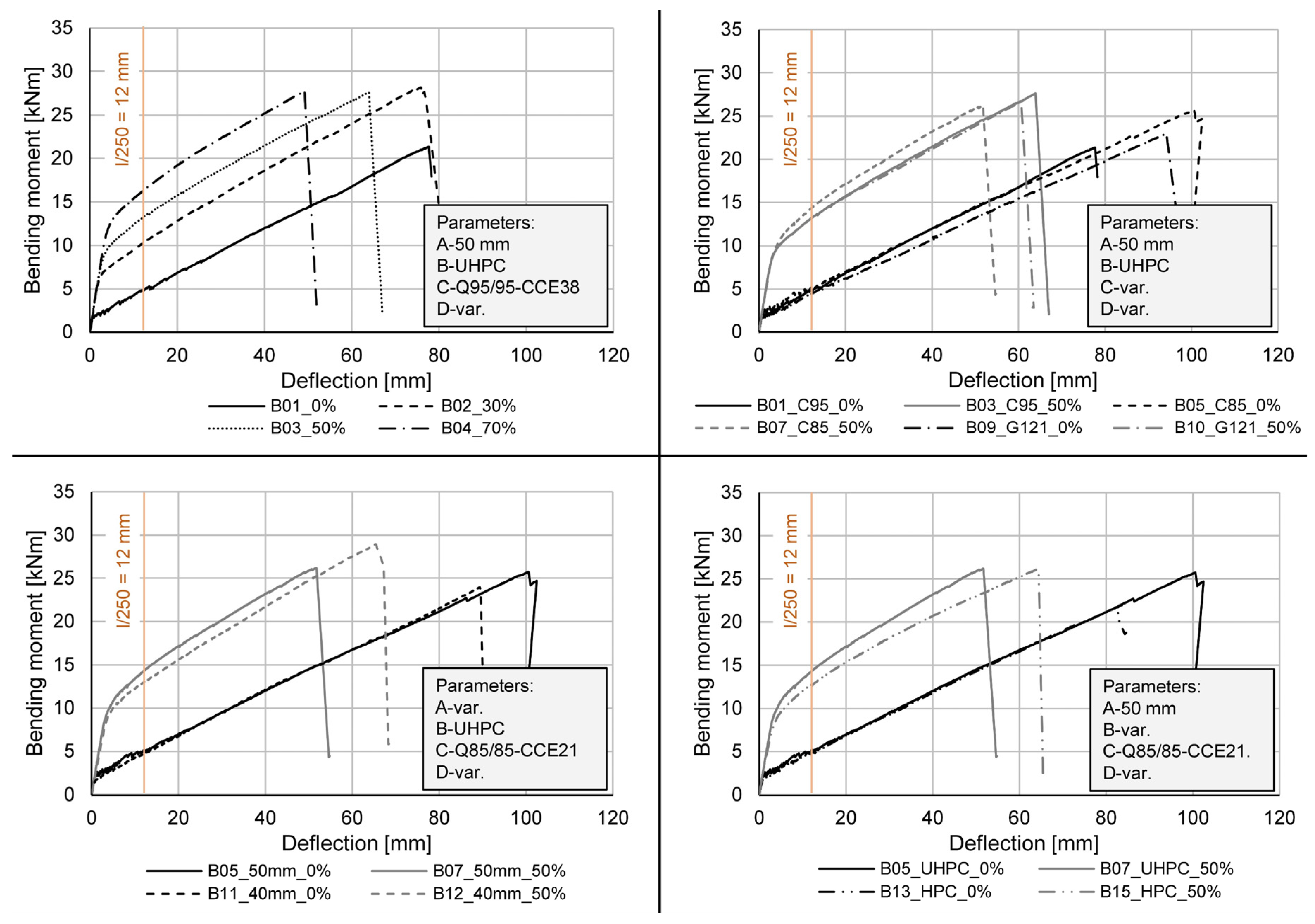
- A reduction of the web thickness to a minimum (parameter A) was presented, ensuring failure of the reinforcement without significant bond problems. The ultimate bending moment Mu of the UHPC beams reinforced with a CFRP bar of 8 mm and the textile reinforcement Q85/85-CCE21 with a web thickness of 40 mm is comparable to the beams with a web thickness of 50 mm. The prestressed beam with this configuration even showed the highest Mu of all tests. Regarding the cracking behaviour a negative influence of the small web thicknesses is observed, presenting itself through an earlier occurrence of splitting cracks.
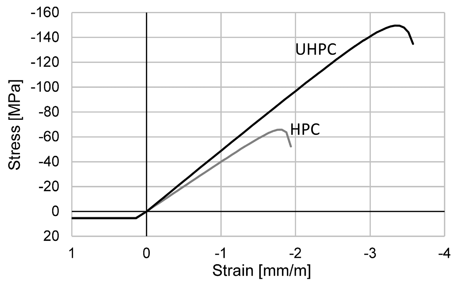
- The prestressed beams with different concrete compressive strengths (parameter B) show equal Mu, with the bending stiffness of the HPC beams inferior to that of the UHPC beams. For the non-prestressed beams an earlier failure of the HPC beam was observed. The easier workability and lower environmental impact however still justify the use of HPC in filigree structures, with the above-mentioned disadvantages counteracted by optimised prestress levels.
- The variation of the mesh reinforcement (material, roving axis distance and roving cross-sectional area) shows no significant differences in the bearing behaviour, especially for the prestressed beams. The non-prestressed beams reinforced with a GFRP mesh show a lower bending stiffness (4 mm higher deflection at a bending moment of 15 kNm, see Figure 6) compared to the beams reinforced with CFRP meshes. Regarding the cracking behaviour the CFRP meshes with small roving axis distance (Q85/85-CCE21) are preferable, due to higher moments when the first bending and splitting cracks occur.
- For all configurations the prestressing of the CFRP bar shows an improvement of the load-bearing behaviour. The ultimate bending moment Mu is increased due to full utilisation of the CFRP bar. In addition, a significant improvement of the structural stiffness and the cracking behaviour in general is observed.
Author Contributions
Funding
Institutional Review Board Statement
Informed Consent Statement
Data Availability Statement
Acknowledgments
Conflicts of Interest
References
- Krausmann, F.; Lauk, C.; Haas, W.; Wiedenhofer, D. From resource extraction to outflows of wastes and emissions: The socioeconomic metabolism of the global economy, 1900–2015. Glob. Environ. Chang. 2018, 52, 131–140. [Google Scholar] [CrossRef] [PubMed]
- Andrew, R.M. Global CO2 emissions from cement production, 1928–2017. Earth Syst. Sci. Data 2018, 10, 195–217. [Google Scholar] [CrossRef] [Green Version]
- Kromoser, B. III Ressourceneffizientes Bauen mit Betonfertigteilen Material-Struktur–Herstellung. In Beton-Kalender 2021, Fertigteile, Integrale Bauwerke; Bergmeister, K., Fingerloos, F., Wörner, J.D., Eds.; Ernst & Sohn: Wien, Austria, 2021; ISBN 978-3-433-03301-2. [Google Scholar]
- Reichenbach, S.; Kromoser, B. State of practice of automation in precast concrete production. J. Build. Eng. 2021, 43, 102527. [Google Scholar] [CrossRef]
- Kromoser, B.; Preinstorfer, P.; Kollegger, J. Building lightweight structures with carbon-fiber-reinforced polymer-reinforced ultra-high-performance concrete: Research approach, construction materials, and conceptual design of three building components. Struct. Concr. 2018, 20, 730–744. [Google Scholar] [CrossRef] [Green Version]
- Stoiber, N.; Kromoser, B. Topology optimization in concrete construction: A systematic review on numerical and experimental investigations. Struct. Multidiscip. Optim. 2021, 64, 1725–1749. [Google Scholar] [CrossRef]
- Haist, M.; Bergmeister, K.; Curbach, M.; Forman, P.; Gaganelis, G.; Gerlach, J.; Mark, P.; Moffatt, J.; Müller, C.; Müller, H.S.; et al. VII Nachhaltig konstruieren und bauen mit Beton. In Beton-Kalender 2022, Nachhaltigkeit, Digitalisierung und Instandhaltung; Bergmeister, K., Fingerloos, F., Wörner, J.D., Eds.; Ernst & Sohn: Wien, Austria, 2022; ISBN 978-3-433-03344-9. [Google Scholar]
- Stoiber, N.; Hammerl, M.; Kromoser, B. Cradle-to-gate life cycle assessment of CFRP reinforcement for concrete structures: Calculation basis and exemplary application. J. Clean. Prod. 2020, 280, 124300. [Google Scholar] [CrossRef]
- Cadenazzi, T.; Dotelli, G.; Rossini, M.; Nolan, S.; Nanni, A. Cost and environmental analyses of reinforcement alternatives for a concrete bridge. Struct. Infrastruct. Eng. 2019, 16, 787–802. [Google Scholar] [CrossRef]
- Hammerl, M.; Kromoser, B. The influence of pretensioning on the load-bearing behaviour of concrete beams reinforced with carbon fibre reinforced polymers. Compos. Struct. 2021, 273, 114265. [Google Scholar] [CrossRef]
- ACI 440.4R-04; Prestressing Concrete Structures with FRP Tendons. American Concrete Institute (ACI): Farmington Hills, MI, USA, 2004.
- JSCE. Recommendation for Design and Construction of Concrete Structures Using Continous Fiber Reinforcing Materials; Research Committee on Continuous Fiber Reinforceing Materials: Tokyo, Japan, 1997. [Google Scholar]
- CAN/CSA-S806-12; Design and Construction of Building Structures with Fibre-Reinforced Polymers. Canadian Standards Association (CSA): Toronto, ON, Canada, 2017.
- CAN/CSA S6-06; Canadian Highway Bridge Design Code. Canadian Standards Association (CSA): Toronto, ON, Canada, 2014.
- International Federation for Structural Concrete (Fib). Fib Model Code for Concrete Structures 2010; FIB: Lausanne, Switzerland, 2013. [Google Scholar]
- Belarbi, A.; Dawood, M.; Poudel, P.; Reda, M.; Tahsiri, H.; Gencturk, B.; Rizkalla, S.H.; Russell, H.G.; National Academies of Sciences, Engineering, and Medicine; Transportation Research Board; et al. Design of Concrete Bridge Beams Prestressed with CFRP Systems; The National Academies Press: Washington, DC, USA, 2019. [Google Scholar] [CrossRef]
- Preinstorfer, P.; Kromoser, B.; Kollegger, J. Flexural behaviour of filigree slab elements made of carbon reinforced UHPC. Constr. Build. Mater. 2018, 199, 416–423. [Google Scholar] [CrossRef]
- Preinstorfer, P.; Kollegger, J. New insights into the splitting failure of textile-reinforced concrete. Compos. Struct. 2020, 243, 112203. [Google Scholar] [CrossRef]
- Bielak, J.; Spelter, A.; Will, I.N.; Claßen, I.M. Verankerungsverhalten textiler Bewehrungen in dünnen Betonbauteilen. Beton Stahlbetonbau 2018, 113, 515–524. [Google Scholar] [CrossRef]
- Suppanz, F.; Kromoser, D.D.B. Verbundverhalten subtraktiv bearbeiteter CFK-Stäbe in UHPC. Beton Stahlbetonbau 2020, 115, 504–513. [Google Scholar] [CrossRef]
- Hammerl, M.; Stoiber, N.; Hämmerle, J.; Shams, I.A.; Bischoff, T.; Kromoser, T.B. Verbundverhalten umwickelter CFK-Stäbe in Beton–Kurzzeituntersuchung der Verbundeigenschaften mittels Pull-out-Tests. Beton Stahlbetonbau 2021, 116, 935–946. [Google Scholar] [CrossRef]
- Stark, A.; Classen, M.; Hegger, J. Bond behaviour of CFRP tendons in UHPFRC. Eng. Struct. 2018, 178, 148–161. [Google Scholar] [CrossRef]
- May, S.; Michler, H.; Schladitz, F.; Curbach, M. Lightweight ceiling system made of carbon reinforced concrete. Struct. Concr. 2018, 19, 1862–1872. [Google Scholar] [CrossRef]
- Goliath, K.B.; Cardoso, D.C.T.; Silva, F.D.A. Flexural behavior of carbon-textile-reinforced concrete I-section beams. Compos. Struct. 2021, 260, 113540. [Google Scholar] [CrossRef]
- Bielak, J.; Schmidt, M.; Hegger, J.; Jesse, F. Structural Behavior of Large-Scale I-Beams with Combined Textile and CFRP Reinforcement. Appl. Sci. 2020, 10, 4625. [Google Scholar] [CrossRef]
- Hegger, J.; Curbach, M.; Stark, A.; Wilhelm, S.; Farwig, K. Innovative design concepts: Application of textile reinforced concrete to shell structures. Struct. Concr. 2017, 19, 637–646. [Google Scholar] [CrossRef]
- Terrasi, G.P. Prefabricated Thin-walled Structural Elements Made from High Performance Concrete Prestressed with CFRP Wires. J. Mater. Sci. Res. 2012, 2, 1–14. [Google Scholar] [CrossRef] [Green Version]
- Osman-Letelier, J.P.; Hückler, I.A.; Schlaich, S.T.M. Dünnwandige Fertigteile aus vorgespanntem Carbonbeton. Beton Stahlbetonbau 2021, 116, 786–797. [Google Scholar] [CrossRef]
- Sydow, A.; Kurath, J.; Steiner, P. Extrem leichte Brücke aus vorgespanntem Carbonbeton: Fahrradbrücke über die Eulach in Winterthur/Schweiz aus vorgespanntem Carbonbeton. Beton Stahlbetonbau 2019, 114, 869–876. [Google Scholar] [CrossRef]
- Stark, A.; Classen, M.; Knorrek, C.; Camps, B.; Hegger, J. Sandwich panels with folded plate and doubly curved UHPFRC facings. Struct. Concr. 2018, 19, 1851–1861. [Google Scholar] [CrossRef]
- Fehling, E.; Schmidt, M.; Walraven, J.C.; Leutbecher, T.; Fröhlich, S. Ultra-High Performance Concrete UHPC: Fundamentals-Design-Examples; Ernst & Sohn: Wien, Austria, 2014; ISBN 978-3-433-03087-5. [Google Scholar]
- ÖNORM EN 12350-7; Testing Fresh Concrete—Part 7, Air Content—Pressure Methods. Austrian Standards Institute: Vienna, Austria, 2019.
- ÖNORM EN 12350-5; Testing Fresh Concrete—Part 5, Flow Table Test. Austrian Standards Institute: Vienna, Austria, 2019.
- ÖNORM EN 12390-3; Testing Hardened Concrete—Part 3, Compressive Strength of Test Specimens. Austrian Standards Institute: Vienna, Austria, 2019.
- ÖNORM EN 12390-6; Testing Hardened Concrete, Part 6, Tensile Splitting Strength of Test Specimens. Austrian Standards Institute: Vienna, Austria, 2010.
- ÖNORM EN 12390-13; Testing of hardened concrete—Part 13, Determination of Secant Modulus of Elasticity in Compression. Austrian Standards Institute: Vienna, Austria, 2021.
- Reichenbach, S.; Preinstorfer, P.; Hammerl, M.; Kromoser, B. A review on embedded fibre-reinforced polymer reinforcement in structural concrete in Europe. Constr. Build. Mater. 2021, 307, 124946. [Google Scholar] [CrossRef]
- Solidian-Führend in Textiler Bewehrung. Available online: https://www.solidian.com/ (accessed on 27 February 2022).
- Dr.-Ing. Uwe Pfeiffer, Ingenieur fürs Bauwesen, Software fürs Bauwesen 2021. Available online: https://www.u-pfeiffer.de/ (accessed on 22 November 2021).
- Hammerl, M.; Kromoser, B. Load-bearing Behaviour of Pretensioned Thin-walled Concrete Structures Reinforced with CFRP. Concrete Structures: New Trends for Eco-Efficiency and Performance. In Proceedings of the Fib Symposium 2021, Lisbon, Portugal, 14–16 June 2021. [Google Scholar]
- Hammerl, M.; Kromoser, B. Bending failure mechanisms of prestressed thin-walled UHPC beams reinforced with CFRP. In Proceedings of the Fib Congress 2022, Concrete Innovation for Sustainability, Oslo, Norway, 12–16 June 2022. (Under Review). [Google Scholar]
- Schmidt, J.W.; Bennitz, A.; Täljsten, B.; Goltermann, P.; Pedersen, H. Mechanical anchorage of FRP tendons—A literature review. Constr. Build. Mater. 2012, 32, 110–121. [Google Scholar] [CrossRef]
- Zdanowicz, K.; Kotynia, R.; Marx, S. Prestressing concrete members with fibre-reinforced polymer reinforcement: State of research. Struct. Concr. 2019, 20, 872–885. [Google Scholar] [CrossRef]
- Hammerl, M.; Reichenbach, S.; Stoiber, N.; Kromoser, B. Short Length Mechanical Bond Anchorage for Reinforcement Bars Made of FRP: Experimental and Numerical Investigations. Mater. Struct. 2022. submitted. [Google Scholar]


| Ingredients | HPC [kg/m3] | UHPC [kg/m3] |
|---|---|---|
| Water | 163 | 170 |
| Superplasticiser | 5 | 32 |
| Defoamer | 1 | 1 |
| Cement | 420 | 712 |
| Microsilica | - | 143 |
| Limestone powder | 100 | 285 |
| Quartz sand 0–4 mm | 1640 | 1030 |
| Properties (Abbreviations) | Specimen Size [mm] | HPC [MPa] | UHPC [MPa] |
|---|---|---|---|
| fctm,fl # | 160 × 40 × 40 | 11.4 # | 10.6 # |
| fctm,sp * | Ø100 × 200 | 5.3 * | 6.3 * |
| fctm + | - | 5.1 #/5.3 */5.2 + | 4.7 #/6.3 */5.5 + |
| Ecm | Ø150 × 300 | 36,654 | 44,506 |
| fcm,cube,45h | 100 × 100 × 100 | 47.3 | 92.0 |
| fcm,cube | 150 × 150 × 150 | 65.9 | 149.6 |
| fcm,cyl | Ø150 × 300 | 60.3 | 162.3 |
| Properties | Rebar CCE 8 | Q85/85-CCE21 | Q95/95-CCE38 | Q121/121-AAE38 |
|---|---|---|---|---|
| Dimension | 1D | 2D | 2D | 2D |
| Fibre/Matrix material | Carbon/Epoxy resin | Carbon/Epoxy resin | Carbon/Epoxy resin | AR-glass/Epoxy resin |
| Roving axis distance | - | 21 mm | 38 mm | 38 mm |
| Cross section of the roving/planar reinforcement | 50.2 mm2 | 1.81 mm2/85 mm2/m | 3.62 mm2/95 mm2/m | 4.62 mm2/121 mm2/m |
| Mean tensile strength | 2500 MPa | 4000 MPa | 3600 MPa | 1300 MPa |
| Char. tensile strength | 2100 MPa | 3300 MPa | 3000 MPa | 1100 MPa |
| Mean Young’s modulus | 158 GPa | 230 GPa | 230 GPa | 73 GPa |
| Mean elongation at break | 15.8‰ | 17.4‰ | 15.7‰ | 17.8‰ |
| Char. elongation at break | 13.3‰ | 14.3‰ | 13.0‰ | 15.1‰ |
| Parameter | Beam No. | |||||||||||||||
|---|---|---|---|---|---|---|---|---|---|---|---|---|---|---|---|---|
| 1 | 2 | 3 | 4 | 5 | 6 | 7 | 8 | 9 | 10 | 11 | 12 | 13 | 14 | 15 | ||
| A—web thickness | 50 mm | |||||||||||||||
| 40 mm | ||||||||||||||||
| B—concrete | UHPC | |||||||||||||||
| HPC | ||||||||||||||||
| C—mesh reinforcement | Q95/95-CCE38 | |||||||||||||||
| Q85/85-CCE21 | ||||||||||||||||
| Q121/121-AAE38 | ||||||||||||||||
| D—prestressing force | 0 kN = 0 MPa = 0% | |||||||||||||||
| 31.7 kN/630 MPa/30% | ||||||||||||||||
| 52.8 kN/1050 MPa/50% | ||||||||||||||||
| 73.9 kN/1470 MPa/70% | ||||||||||||||||
| Beam No. | Mu | DM,u | Mbe,cr | Msp,cr | Mcr,fin | W20kNm | Failure Mode |
|---|---|---|---|---|---|---|---|
| [kNm] | [mm] | [kNm] | [kNm] | [kNm] | [mm] | [-] | |
| B01_UHPC_C95_50_0% | 21.3 | 76.6 | 1.7 | 10.1 | 8.2 | 0.70 | Roving |
| B02_UHPC_C95_50_30% | 28.2 | 75.6 | 5.4 | 18.2 | 14.5 | 0.41 | Bar |
| B03_UHPC_C95_50_50% | 27.6 | 64.1 | 7.1 | 15.5 | 14.5 | 0.37 | Bar |
| B04_UHPC_C95_50_70% | 27.7 | 49.4 | 9.8 | 19.5 | 15.3 | 0.20 | Bar |
| B05_UHPC_C85_50_0% | 25.7 | 98.4 | 2.5 | 9.7 | 10.3 | 0.40 | Roving |
| B06_UHPC_C85_50_0% | 24.2 | 98.6 | 1.7 | 12.6 | 8.3 | 0.53 | Roving |
| B07_UHPC_C85_50_50% | 26.2 | 51.6 | 8.6 | 23.9 | 19.3 | 0.34 | Bar |
| B08_UHPC_C85_50_70% | 27.1 | 48.0 | 10.4 | 25.1 | 19.5 | 0.23 | Bar |
| B09_UHPC_G121_50_0% | 22.9 | 94.4 | 1.5 | 10.0 | 18.4 | 0.57 | Bar |
| B10_UHPC_G121_50_50% | 26.6 | 60.7 | 7.7 | 22.2 | 20.6 | 0.32 | Bar |
| B11_UHPC_C85_40_0% | 24.0 | 87.6 | 1.6 | 8.1 | 8.0 | 0.43 | Roving |
| B12_UHPC_C85_40_50% | 28.9 | 65.5 | 7.9 | 16.3 | 13.7 | 0.27 | Bar |
| B13_HPC_C85_50_0% | 22.0 | 82.9 | 1.5 | 7.5 | 9.3 | 0.62 | Roving |
| B14_HPC_C85_50_30% | 27.6 | 80.8 | 4.9 | 18.8 | 14.5 | 0.46 | Bar |
| B15_HPC_C85_50_50% | 26.1 | 65.0 | 7.8 | 21.0 | 15.8 | 0.44 | Bar |
| Mu | Mcr | σroving | σbar | σconcrete | |||||||
|---|---|---|---|---|---|---|---|---|---|---|---|
| [kNm] | [kNm] | [MPa] | [MPa] | [MPa] | |||||||
| exp | calcchar. | calcmean | exp | calc | calcchar. | calcmean | calcchar. | calcmean | calcchar. | calcmean | |
| B01_UHPC_C95_50_0% | 21.3 | 27.2 | 32.9 | 1.7 | 2.1 | 3000 | 3600 | 1979 | 2394 | −71 | −85 |
| B02_UHPC_C95_50_30% | 28.2 | 26.3 | 31.7 | 5.4 | 6.6 | 2230 | 2810 | 2100 | 2500 | −66 | −80 |
| B03_UHPC_C95_50_50% | 27.6 | 24.3 | 29.8 | 7.1 | 9.9 | 1593 | 2178 | 2100 | 2500 | −57 | −72 |
| B04_UHPC_C95_50_70% | 27.7 | 22.3 | 27.9 | 9.8 | 13.2 | 956 | 1550 | 2100 | 2500 | −47 | −63 |
| B05_UHPC_C85_50_0% | 25.7 | 26.7 | 31.8 | 2.5 | 2.0 | 3300 | 3911 | 2093 | 2500 | −73 | −86 |
| B06_UHPC_C85_50_0% | 24.2 | 26.7 | 31.8 | 1.7 | 2.0 | 3300 | 3911 | 2093 | 2500 | −73 | −86 |
| B07_UHPC_C85_50_50% | 26.2 | 23.0 | 28.1 | 8.6 | 9.6 | 1655 | 2267 | 2100 | 2500 | −56 | −71 |
| B08_UHPC_C85_50_70% | 27.1 | 21.4 | 26.5 | 10.4 | 12.7 | 999 | 1614 | 2100 | 2500 | −47 | −62 |
| B09_UHPC_G121_50_0% | 22.9 | 22.8 | 27.1 | 1.5 | 2.0 | 1011 | 1196 | 2100 | 2500 | −66 | −78 |
| B10_UHPC_G121_50_50% | 26.6 | 21.4 | 25.8 | 7.7 | 9.8 | 506 | 694 | 2100 | 2500 | −54 | −68 |
| B11_UHPC_C85_40_0% | 24.0 | 26.8 | 31.9 | 1.6 | 1.7 | 3262 | 3861 | 2100 | 2500 | −72 | −86 |
| B12_UHPC_C85_40_50% | 28.9 | 23.3 | 28.4 | 7.9 | 9.9 | 1637 | 2239 | 2100 | 2500 | −56 | −70 |
| B13_HPC_C85_50_0% | 22.0 | 26.7 | 29,3 | 1.5 | 1.7 | 3267 | 3574 | 2100 | 2310 | −63 | −66 |
| B14_HPC_C85_50_30% | 27.6 | 24.7 | 29.7 | 4.9 | 6.4 | 2291 | 2895 | 2100 | 2500 | −57 | −66 |
| B15_HPC_C85_50_50% | 26.1 | 23.1 | 28.2 | 7.8 | 9.6 | 1635 | 2243 | 2100 | 2500 | −51 | −62 |
Publisher’s Note: MDPI stays neutral with regard to jurisdictional claims in published maps and institutional affiliations. |
© 2022 by the authors. Licensee MDPI, Basel, Switzerland. This article is an open access article distributed under the terms and conditions of the Creative Commons Attribution (CC BY) license (https://creativecommons.org/licenses/by/4.0/).
Share and Cite
Hammerl, M.; Kromoser, B. Bending Behaviour of Prestressed T-Shaped Concrete Beams Reinforced with FRP—Experimental and Analytical Investigations. Materials 2022, 15, 3843. https://doi.org/10.3390/ma15113843
Hammerl M, Kromoser B. Bending Behaviour of Prestressed T-Shaped Concrete Beams Reinforced with FRP—Experimental and Analytical Investigations. Materials. 2022; 15(11):3843. https://doi.org/10.3390/ma15113843
Chicago/Turabian StyleHammerl, Mathias, and Benjamin Kromoser. 2022. "Bending Behaviour of Prestressed T-Shaped Concrete Beams Reinforced with FRP—Experimental and Analytical Investigations" Materials 15, no. 11: 3843. https://doi.org/10.3390/ma15113843
APA StyleHammerl, M., & Kromoser, B. (2022). Bending Behaviour of Prestressed T-Shaped Concrete Beams Reinforced with FRP—Experimental and Analytical Investigations. Materials, 15(11), 3843. https://doi.org/10.3390/ma15113843