
Ultrasound Effect on the Microstructure and Hardness of AlMg3 Alloy under Upsetting

 ,
, 
 , , and
Abstract
1. Introduction
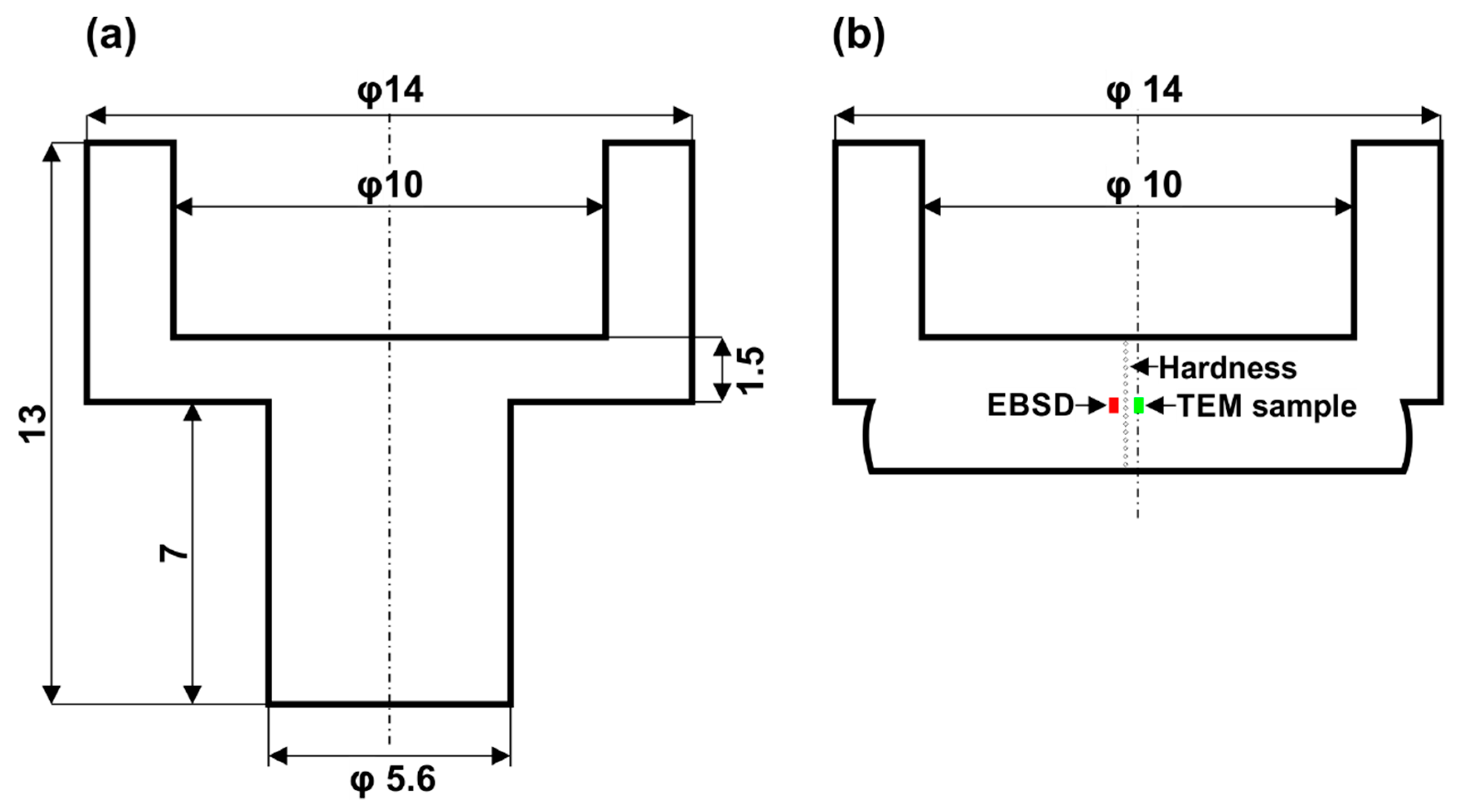
2. Materials and Methods
- condition 1—upsetting by 80% without the ultrasonic excitation;
- condition 2—upsetting by 80% with the ultrasonic excitation. In this condition, ultrasonic excitation was applied for two intervals. First, at an ε = 0.03 for 12 s, then discontinued and, after 18 s of continued static compression, was applied again for 12 s.
3. Results
3.1. Light Microscopy
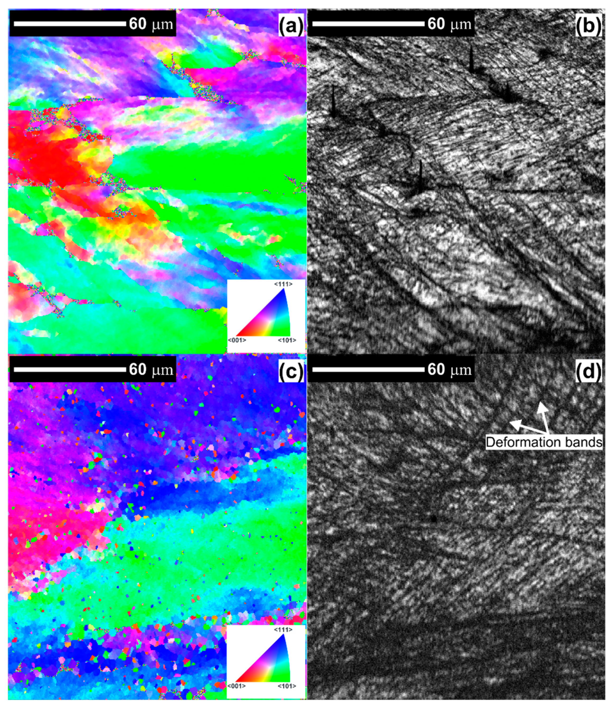
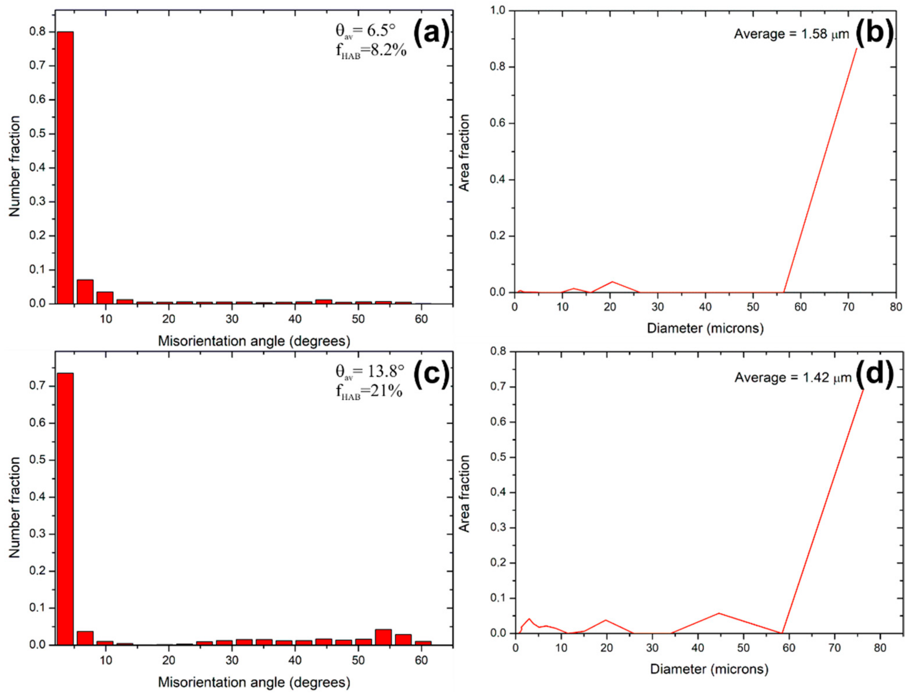
3.2. EBSD Analysis
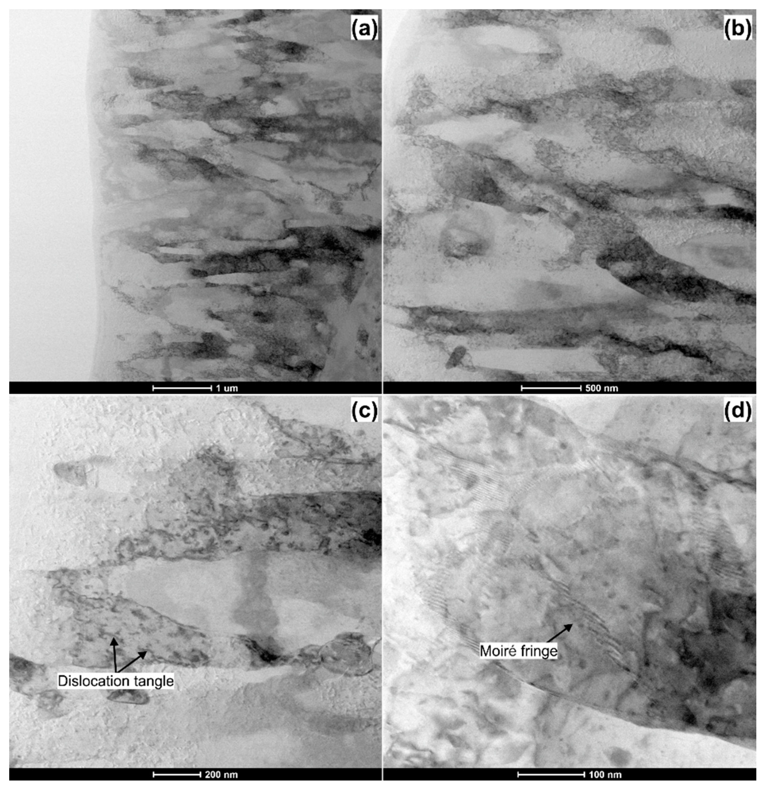
3.3. TEM Analysis
3.4. Flow Stress Analysis
3.5. Hardness
4. Conclusions
- The application of ultrasonic vibrations may initiate the shear bands formations intensifying the grain refinement. In this study, the ultra-fine grained (UFG) AlMg3 alloy with the sub-grain size of about 1 µm was obtained;
- A temporary acoustic softening was observed after excitation of the sample by ultrasonic energy during compression test, and the residual hardening phenomenon was illustrated once the vibration was stopped off after the process;
- Ultrasonic vibrations promote continuous propagation of the bands bringing about the Portevin–Le Chatelier effect (PLC) in AlMg3 alloy during upsetting;
- The effect of ultrasonic vibration—acoustic hardening as well as an increase in dislocation density and change in microstructural characteristics—grain refinement, is closely related to the observed increase in hardness value of investigated AlMg3 aluminum alloy.
Author Contributions
Funding
Institutional Review Board Statement
Informed Consent Statement
Data Availability Statement
Acknowledgments
Conflicts of Interest
References
- Afseth, A. Ultra-High-Strength Aluminium Alloys—Vehicle Production’s Next Big Thing. Light. Des. Worldw. 2017, 10, 12–15. [Google Scholar] [CrossRef]
- Igliński, H.; Babiak, M. Analysis of the Potential of Autonomous Vehicles in Reducing the Emissions of Greenhouse Gases in Road Transport. Procedia Eng. 2017, 192, 353–358. [Google Scholar] [CrossRef]
- Federal Ministry for Environment Nature Conservation Climate Action Plan 2050—Principles and Goals of the German Government’s Climate Policy. Germany. 2016. Available online: https://www.bmu.de/en/download/climate-action-plan-2050/ (accessed on 19 February 2021).
- Koffler, C.; Rohde-Brandenburger, K. On the calculation of fuel savings through lightweight design in automotive life cycle assessments. Int. J. Life Cycle Assess. 2010, 15, 128–135. [Google Scholar] [CrossRef]
- Snopiński, P.; Tański, T.; Gołombek, K.; Rusz, S.; Hilser, O.; Donič, T.; Nuckowski, P.M.; Benedyk, M. Strengthening of AA5754 Aluminum Alloy by DRECE Process Followed by Annealing Response Investigation. Materials 2020, 13, 301. [Google Scholar] [CrossRef] [PubMed]
- Król, M.; Snopiński, P.; Pagáč, M.; Hajnyš, J.; Petrů, J. Hot Deformation Treatment of Grain-Modified Mg–Li Alloy. Materials 2020, 13, 4557. [Google Scholar] [CrossRef] [PubMed]
- Modaresi, R.; Pauliuk, S.; Løvik, A.N.; Müller, D.B. Global Carbon Benefits of Material Substitution in Passenger Cars until 2050 and the Impact on the Steel and Aluminum Industries. Environ. Sci. Technol. 2014, 48, 10776–10784. [Google Scholar] [CrossRef]
- Kim, H.C.; Wallington, T.J. Life Cycle Assessment of Vehicle Lightweighting: A Physics-Based Model To Estimate Use-Phase Fuel Consumption of Electrified Vehicles. Environ. Sci. Technol. 2016, 50, 11226–11233. [Google Scholar] [CrossRef]
- Kroll, L.; Blau, P.; Wabner, M.; Frieß, U.; Eulitz, J.; Klärner, M. Lightweight components for energy-efficient machine tools. CIRP J. Manuf. Sci. Technol. 2011, 4, 148–160. [Google Scholar] [CrossRef]
- Tisza, M.; Czinege, I. Comparative study of the application of steels and aluminium in lightweight production of automotive parts. Int. J. Light. Mater. Manuf. 2018, 1, 229–238. [Google Scholar] [CrossRef]
- Liu, Y.; Liu, M.; Chen, X.; Cao, Y.; Roven, H.J.; Murashkin, M.; Valiev, R.Z.; Zhou, H. Effect of Mg on microstructure and mechanical properties of Al-Mg alloys produced by high pressure torsion. Scr. Mater. 2019, 159, 137–141. [Google Scholar] [CrossRef]
- Miller, W.; Zhuang, L.; Bottema, J.; Wittebrood, A.; De Smet, P.; Haszler, A.; Vieregge, A. Recent development in aluminium alloys for the automotive industry. Mater. Sci. Eng. A 2000, 280, 37–49. [Google Scholar] [CrossRef]
- Snopiński, P.; Król, M.; Wróbel, T.; Matus, K.; Woźniak, A.; Tański, T.; Palček, P. Effects of modifying the hypoeutectic AlMg5Si2Mn alloy via addition of Al10Sr and/or Al5TiB. Arch. Civ. Mech. Eng. 2021, 21, 1–16. [Google Scholar] [CrossRef]
- Krol, M.; Snopiński, P.; Tomiczek, B.; Tański, T.; Pakieła, W.; Sitek, W. Structure and properties of an Al alloy in as-cast state and after laser treatment. Proc. Estonian Acad. Sci. 2016, 65, 107. [Google Scholar] [CrossRef]
- Tański, T.; Snopiński, P.; Prusik, K.; Sroka, M. The effects of room temperature ECAP and subsequent aging on the structure and properties of the Al-3%Mg aluminium alloy. Mater. Charact. 2017, 133, 185–195. [Google Scholar] [CrossRef]
- Horita, Z.; Furukawa, M.; Nemoto, M.; Barnes, A.; Langdon, T. Superplastic forming at high strain rates after severe plastic deformation. Acta Mater. 2000, 48, 3633–3640. [Google Scholar] [CrossRef]
- Liu, F.; Ma, Z. Achieving exceptionally high superplasticity at high strain rates in a micrograined Al–Mg–Sc alloy produced by friction stir processing. Scr. Mater. 2008, 59, 882–885. [Google Scholar] [CrossRef]
- Zhong, H.; Rometsch, P.A.; Wu, X.; Cao, L.; Estrin, Y. Influence of pre-ageing on the stretch formability of Al-Mg-Si automotive sheet alloys. Mater. Sci. Eng. A 2017, 697, 79–85. [Google Scholar] [CrossRef]
- Pohlman, R.; Lehfeldt, E. Influence of ultrasonic vibration on metallic friction. Ultrasonics 1966, 4, 178–185. [Google Scholar] [CrossRef]
- Bai, Y.; Yang, M. Optimization of metal foils surface finishing using vibration-assisted micro-forging. J. Mater. Process. Technol. 2014, 214, 21–28. [Google Scholar] [CrossRef]
- Graff, K.F. Ultrasonic metal forming: Materials. In Power Ultrasonics: Applications of High-Intensity Ultrasound; Woodhead Publishing: Cambridge, UK, 2015; ISBN 9781782420361. [Google Scholar] [CrossRef]
- Zhou, H.; Cui, H.; Qin, Q.-H.; Wang, H.; Shen, Y. A comparative study of mechanical and microstructural characteristics of aluminium and titanium undergoing ultrasonic assisted compression testing. Mater. Sci. Eng. A 2017, 682, 376–388. [Google Scholar] [CrossRef]
- Pal, D.; Stucker, B. A study of subgrain formation in Al 3003 H-18 foils undergoing ultrasonic additive manufacturing using a dislocation density based crystal plasticity finite element framework. J. Appl. Phys. 2013, 113, 203517. [Google Scholar] [CrossRef]
- Hung, J.-C.; Tsai, Y.-C. Investigation of the effects of ultrasonic vibration-assisted micro-upsetting on brass. Mater. Sci. Eng. A 2013, 580, 125–132. [Google Scholar] [CrossRef]
- Donič, T.; Raab, G.; Aksenov, D.; Asfandiyarov, R.; Hadzima, B. Ultrasound effect on structure and properties of Cu–0.5Cr under upsetting. Mater. Sci. Technol. 2020, 36, 933–938. [Google Scholar] [CrossRef]
- Liu, Y.; Suslov, S.; Han, Q.; Xu, C.; Hua, L. Microstructure of the pure copper produced by upsetting with ultrasonic vibration. Mater. Lett. 2012, 67, 52–55. [Google Scholar] [CrossRef]
- Bagherzadeh, S.; Abrinia, K. Effect of Ultrasonic Vibration on Compression Behavior and Microstructural Characteristics of Commercially Pure Aluminum. J. Mater. Eng. Perform. 2015, 24, 4364–4376. [Google Scholar] [CrossRef]
- Samigullina, A.; Mukhametgalina, A.; Sergeyev, S.; Zhilyaev, A.; Nazarov, A.; Zagidullina, Y.; Parkhimovich, N.; Rubanik, V.; Tsarenko, Y. Microstructure changes in ultrafine-grained nickel processed by high pressure torsion under ultrasonic treatment. Ultrasonics 2018, 82, 313–321. [Google Scholar] [CrossRef] [PubMed]
- Hung, J.-C.; Lin, C.-C. Investigations on the material property changes of ultrasonic-vibration assisted aluminum alloy upsetting. Mater. Des. 2013, 45, 412–420. [Google Scholar] [CrossRef]
- Brynk, T.; Kurzydlowski, K.J. Coupling of ultrasounds with the Portevin–Le Chatelier serrations as observed in aluminium-magnesium alloy in mini-samples tensile tests. Scr. Mater. 2020, 174, 14–18. [Google Scholar] [CrossRef]
- Xie, Z.; Guan, Y.; Lin, J.; Zhai, J.; Zhu, L. Constitutive model of 6063 aluminum alloy under the ultrasonic vibration upsetting based on Johnson-Cook model. Ultrasonics 2019, 96, 1–9. [Google Scholar] [CrossRef]
- Cao, M.; Hu, H.; Jia, X.; Tian, S.; Zhao, C.; Han, X. Mechanism of ultrasonic vibration assisted upsetting of 6061 aluminum alloy. J. Manuf. Process. 2020, 59, 690–697. [Google Scholar] [CrossRef]
- Hung, J.-C.; Hung, C. The influence of ultrasonic-vibration on hot upsetting of aluminum alloy. Ultrasonics 2005, 43, 692–698. [Google Scholar] [CrossRef]
- Król, M.; Tański, T.; Snopiński, P.; Tomiczek, B. Structure and properties of aluminium–magnesium casting alloys after heat treatment. J. Therm. Anal. Calorim. 2016, 127, 299–308. [Google Scholar] [CrossRef]
- Beausir, J.-J.F. Analysis Tools for Electron and X-ray Diffraction, ATEX—Software 2007; Université de Lorraine-Metz: Metz, France, 2017; Available online: www.atex-software.eu.
- Madhavan, R.; Kalsar, R.; Ray, R.K.; Suwas, S. IOP Conference Series: Materials Science and Engineering, Proceedings of the 17th International Conference on Textures of Materials (ICOTOM 17), Dresden, Germany, 24–29 August 2014; IOP Publishing: Bristol, UK, 2015. [Google Scholar]
- Hu, J.; Shimizu, T.; Yoshino, T.; Shiratori, T.; Yang, M. Evolution of acoustic softening effect on ultrasonic-assisted micro/meso-compression behavior and microstructure. Ultrasonics 2020, 107, 106107. [Google Scholar] [CrossRef]
- Zhou, H.; Cui, H.; Qin, Q.H. Influence of ultrasonic vibration on the plasticity of metals during compression process. J. Mater. Process. Technol. 2018, 251, 146–159. [Google Scholar] [CrossRef]
- Siu, K.; Ngan, A.; Jones, I. New insight on acoustoplasticity—Ultrasonic irradiation enhances subgrain formation during deformation. Int. J. Plast. 2011, 27, 788–800. [Google Scholar] [CrossRef]
- Bakai, S.A.; Smolianets, R.V.; Kovtun, K.V.; Moskalenko, V.A.; Bakai, A.S. High Frequency Vibrations Impact on Mechanical Properties of Nanocrystalline Titanium. Metallofiz. Noveishie Tekhnol. 2016, 38, 189–203. [Google Scholar] [CrossRef][Green Version]
- Apps, P.J.; Berta, M.; Prangnell, P.B. The effect of dispersoids on the grain refinement mechanisms during deformation of aluminium alloys to ultra-high strains. Acta Mater. 2005, 53, 499–511. [Google Scholar] [CrossRef]
- Tang, L.; Peng, X.; Huang, J.; Ma, A.; Deng, Y.; Xu, G. Microstructure and mechanical properties of severely deformed Al-Mg-Sc-Zr alloy and their evolution during annealing. Mater. Sci. Eng. A 2019, 754, 295–308. [Google Scholar] [CrossRef]
- Cabibbo, M. Microstructure strengthening mechanisms in different equal channel angular pressed aluminum alloys. Mater. Sci. Eng. A 2013, 560, 413–432. [Google Scholar] [CrossRef]
- Langenecker, B. Effects of Ultrasound on Deformation Characteristics of Metals. IEEE Trans. Sonics Ultrason. 1966, 13, 1–8. [Google Scholar] [CrossRef]
- Cabibbo, M.; Evangelista, E.; Scalabroni, C. EBSD FEG-SEM, TEM and XRD techniques applied to grain study of a commercially pure 1200 aluminum subjected to equal-channel angular-pressing. Micron 2005, 36, 401–414. [Google Scholar] [CrossRef] [PubMed]
- Dutta, R.K.; Petrov, R.H.; Hermans, M.J.M.; Richardson, I.M. Accommodation of Plastic Deformation by Ultrasound-Induced Grain Rotation. Met. Mater. Trans. A 2015, 46, 3414–3422. [Google Scholar] [CrossRef]
- Bagherpour, E.; Pardis, N.; Reihanian, M.; Ebrahimi, R. An overview on severe plastic deformation: Research status, techniques classification, microstructure evolution, and applications. Int. J. Adv. Manuf. Technol. 2019, 100, 1647–1694. [Google Scholar] [CrossRef]
- Dutta, R.; Petrov, R.; Delhez, R.; Hermans, M.; Richardson, I.; Böttger, A. The effect of tensile deformation by in situ ultrasonic treatment on the microstructure of low-carbon steel. Acta Mater. 2013, 61, 1592–1602. [Google Scholar] [CrossRef]
- Yao, Z.; Kim, G.-Y.; Wang, Z.; Faidley, L.; Zou, Q.; Mei, D.; Chen, Z. Acoustic softening and residual hardening in aluminum: Modeling and experiments. Int. J. Plast. 2012, 39, 75–87. [Google Scholar] [CrossRef]
- Wang, C.; Zhang, W.; Cheng, L.; Zhu, C.; Wang, X.; Han, H.; He, H.; Hua, R. Investigation on Microsheet Metal Deformation Behaviors in Ultrasonic-Vibration-Assisted Uniaxial Tension with Aluminum Alloy 5052. Materials 2020, 13, 637. [Google Scholar] [CrossRef]
- Lunev, A.; Nadezhkin, M.; Barannikova, S.; Zuev, L. Acoustic Parameters as Criteria of Localized Deformation in Aluminum Alloys. Acta Phys. Pol. A 2018, 134, 342–345. [Google Scholar] [CrossRef]
- Snopińśki, P.; Tański, T.; Matus, K.; Rusz, S. Microstructure, grain refinement and hardness of Al–3%Mg aluminium alloy processed by ECAP with helical die. Arch. Civ. Mech. Eng. 2019, 19, 287–296. [Google Scholar] [CrossRef]


| Element | Mg | Fe | Si | Cu | Ti | Al |
|---|---|---|---|---|---|---|
| Mass, % | 3.1 | 0.07 | 0.07 | 0.01 | 0.01 | balance |
Publisher’s Note: MDPI stays neutral with regard to jurisdictional claims in published maps and institutional affiliations. |
© 2021 by the authors. Licensee MDPI, Basel, Switzerland. This article is an open access article distributed under the terms and conditions of the Creative Commons Attribution (CC BY) license (http://creativecommons.org/licenses/by/4.0/).
Share and Cite
Snopiński, P.; Donič, T.; Tański, T.; Matus, K.; Hadzima, B.; Bastovansky, R. Ultrasound Effect on the Microstructure and Hardness of AlMg3 Alloy under Upsetting. Materials 2021, 14, 1010. https://doi.org/10.3390/ma14041010
Snopiński P, Donič T, Tański T, Matus K, Hadzima B, Bastovansky R. Ultrasound Effect on the Microstructure and Hardness of AlMg3 Alloy under Upsetting. Materials. 2021; 14(4):1010. https://doi.org/10.3390/ma14041010
Chicago/Turabian StyleSnopiński, Przemysław, Tibor Donič, Tomasz Tański, Krzysztof Matus, Branislav Hadzima, and Ronald Bastovansky. 2021. "Ultrasound Effect on the Microstructure and Hardness of AlMg3 Alloy under Upsetting" Materials 14, no. 4: 1010. https://doi.org/10.3390/ma14041010
APA StyleSnopiński, P., Donič, T., Tański, T., Matus, K., Hadzima, B., & Bastovansky, R. (2021). Ultrasound Effect on the Microstructure and Hardness of AlMg3 Alloy under Upsetting. Materials, 14(4), 1010. https://doi.org/10.3390/ma14041010