1. Introduction
In recent years, the penetration of distributed energy resources (DERs), such as solar photovoltaic (PV) systems, energy storage systems, and wind generation, has increased. Locating DERs close to the load is advantageous in terms of reducing transmission losses as well as enhancing operational reliability. However, there are some technical issues associated with the widespread proliferation of DERs in distribution systems, such as current level, protection coordination, voltage rise, and reverse power. An emerging and promising philosophy of operation to mitigate these issues is to designate relatively small areas of a distribution network that embed DERs and loads, and to operate them in a deliberate and controlled way. Such subnetworks are referred to as microgrids [
1,
2,
3,
4,
5].
Low-inertia microgrids are built using inverter-based DERs. Inverter-based DERs differ from conventional rotating machine-based generators when responding to network faults. The inverter-based DERs are usually not able to contribute with large currents. The fault-current capability of an inverter-based DER is limited by the short-time current carrying capacity of the semiconductor switches [
6,
7]. The use of low-inertia microgrids has resulted in some technical challenges, one of which concerns the protection schemes of low-inertia microgrids. A low fault current level will be insufficient to activate conventional over-current protection schemes in an autonomous mode of operation [
8,
9,
10,
11]. However, the fault currents may be large due to the contribution of the grounded host grid in the grid-connected mode of operation. Thus, protection schemes for low-inertia microgrids differ from those of traditional distribution systems. The protection schemes should protect the microgrids in both grid-connected and autonomous modes. For the utility grid fault, the microgrid will change from the grid connected mode of operation to the autonomous mode of operation. After the grid fault is cleared, the microgrid will be reconnected to the host grid. Fault-ride through capability of microgrid will be considered for the microgrid protection schemes [
12,
13].
A low-inertia microgrid is designated as a secondary distribution system and is supplied by a step-down transformer. To detect a low-inertia microgrid fault in the grid-connected mode and autonomous mode, here, we consider a Y/Δ winding configuration for the step-down transformer. Thus, the low-inertia microgrid is similar to a conventional ungrounded distribution system. Ungrounded systems are power systems with no intentionally applied grounding. Single line-to-ground (SLG) faults in ungrounded systems do not lead to large currents. However, during an SLG fault, ungrounded systems are subject to high and destructive transient overvoltages and are also potential hazards to equipment and personnel. Thus, locating and isolating the SLG fault is important in an ungrounded distribution system [
14,
15,
16].
There are many protection methods for microgrids, such as communication-based protection methods, methods based on local measurements, or methods using external devices. The communication-based methods solve the protection problem by automatically adjusting the relay settings by means of online communication systems [
17,
18,
19,
20]. However, a synchronous generator-based DER is required to provide a sufficient fault current for protection. The authors of [
17,
18] presented an adaptive protection scheme for a university campus microgrid using communication-assisted relays. A hierarchical protection scheme was proposed. However, a synchronous generator is needed in the microgrid to provide sufficient fault currents in autonomous mode. The authors of [
19,
20] proposed hybrid protection systems for microgrids. The hybrid microgrid protection system implements a traditional differential protection scheme along with an adaptive microgrid protection scheme. However, this hybrid protection system has not yet been validated experimentally. The other kinds of methods are based on local measurements without communication. In [
21], a microgrid protection strategy, based on overcurrent and a directional negative sequence, was proposed. The current is measured by utilizing the principles of synchronized phasor measurements. In [
22], the coordination of digital relays based on wavelet packet transform is used for detecting and clearing the faults. Finally, there are methods that propose the use of external devices for protection. In [
23], a microgrid protection strategy based on energy storage systems with high fault current capability and fault current limiters was proposed. However, this method has a drawback because it is a very expensive protection solution.
For a single-phase-to-ground fault in ungrounded power distribution systems, Dong and Shi [
24] studied a single-phase-to-ground fault feeder selection using a zero-sequence current in all feeders radiating from the same bus bar; a feeder selection method based on all the feeders’ current amplitudes and phase comparison was proposed. Dong and Bi [
25] analyzed traveling waves generated in single-phase-to-ground faults in an ungrounded system. The traveling wave information during a permanent fault was recorded. The proposed method in this paper can clear up SLG faults at ungrounded systems.
This paper presents a novel protection method for SLG faults in ungrounded low-inertia microgrids. The proposed method includes microgrid interface protection and unit protection. The microgrid interface protection is based on the difference between the zero-sequence voltage angle and the zero-sequence current angle at the microgrid interconnection transformer. The microgrid unit protection is based on a comparison of the three zero-sequence current phase directions at each junction point of load or distributed energy resources. The proposed protection method can respond to SLG faults in both the grid and the microgrid.
In the literature, there are many protection methods relying on communication. The proposed unit protection can detect the fault status and fault direction by itself. The proposed method requires communications only when there is an event in the system. By the coordination of unit protections and interface protection, the fault section can be located.
The remainder of the paper is organized as follows.
Section 2 gives an overview of the major protection issues in microgrids,
Section 3 describes the proposed protection method for low-inertia microgrids,
Section 4 presents the simulation results for a low-inertia microgrid and protection system, and conclusions are provided in
Section 5.
2. Faults in Grid-Connected and Autonomous Modes
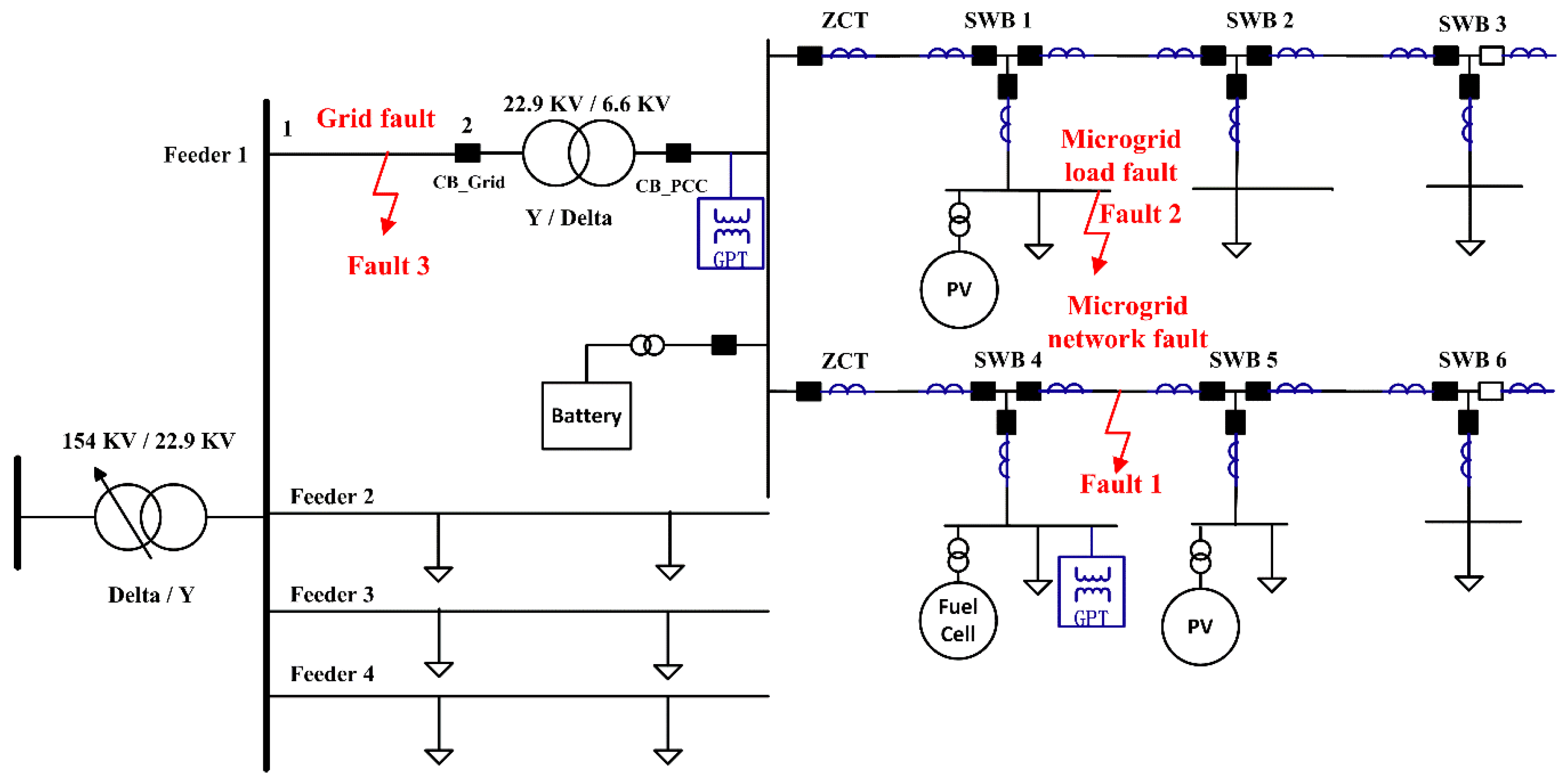
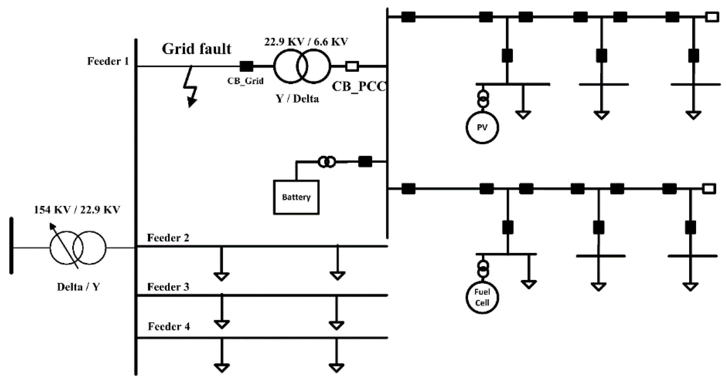
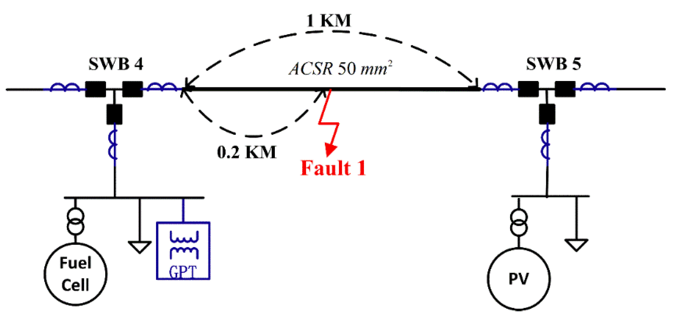
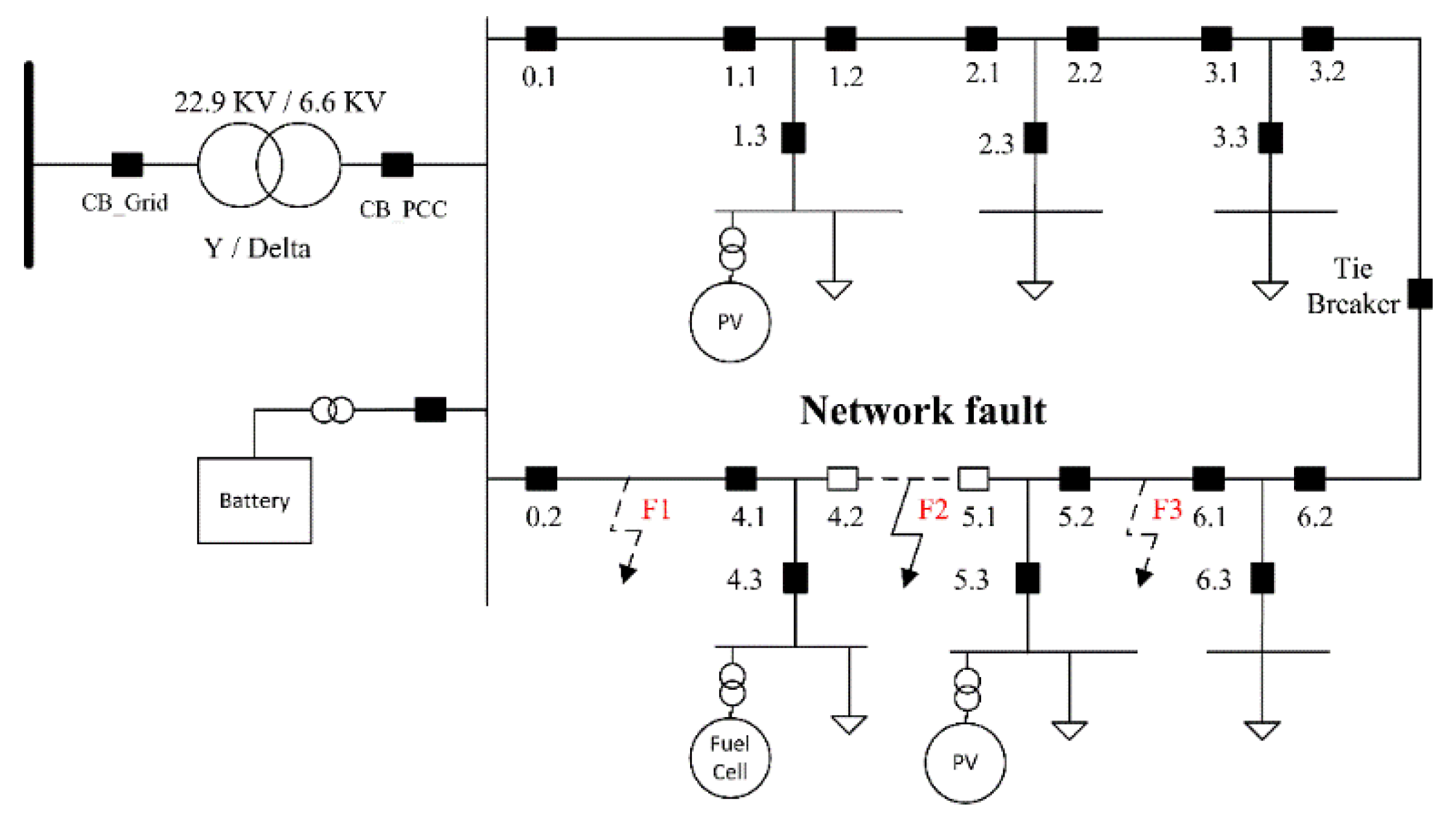
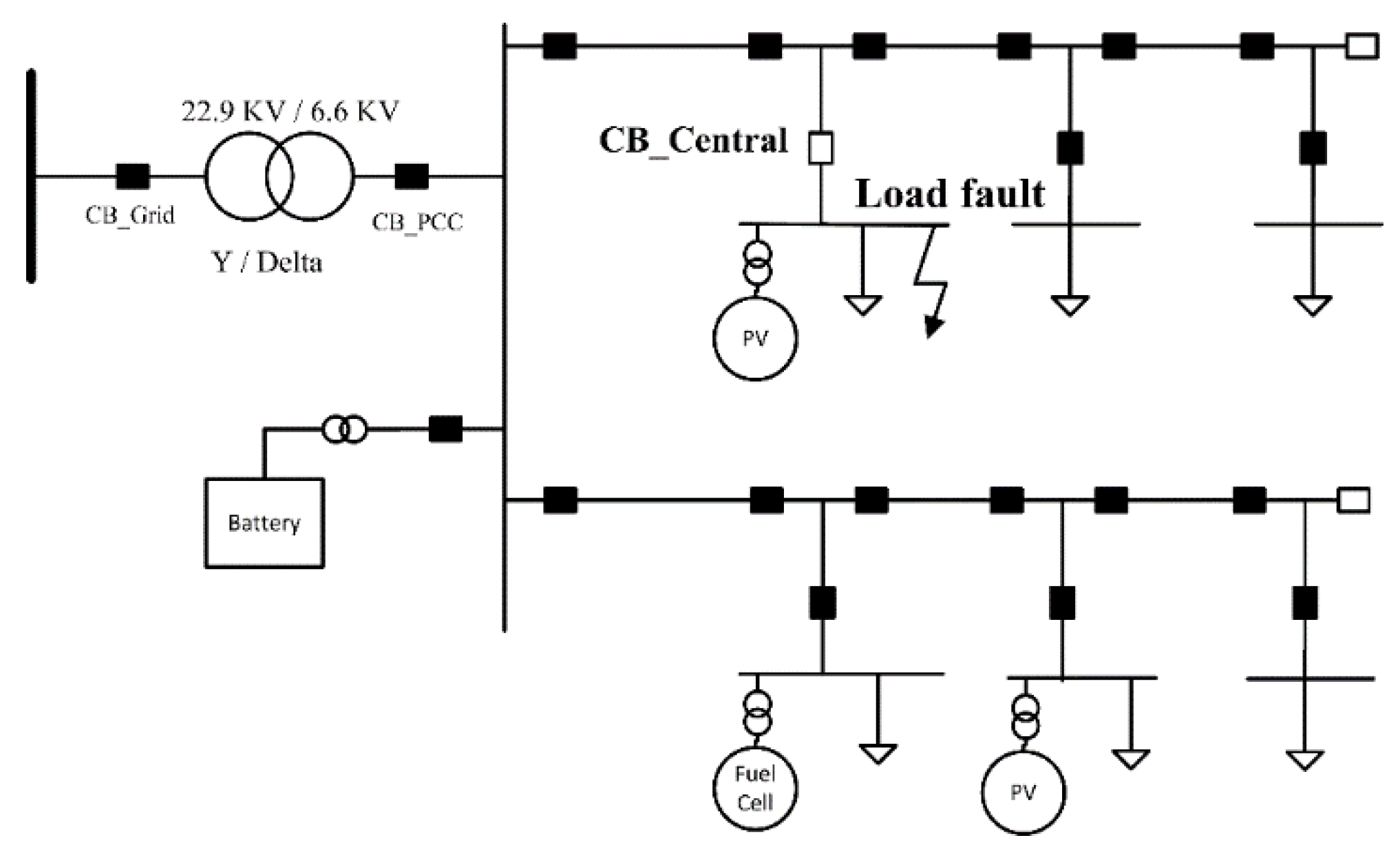
Figure 1 shows the structure of the low-inertia microgrid considered in this paper. The microgrid was interconnected with a distribution system via a Y/Δ step-down transformer. The short circuit capacity of the grid was 100 MVA. The distribution system was grounded and the microgrid was ungrounded. In the medium-voltage distribution system, four feeders were connected to the substation. In the microgrid, two feeders were connected to the point of common coupling (PCC) via a distribution line and each feeder had a circuit breaker (CB). There were three switchboards (SWBs) on each microgrid feeder. Also, three CBs were installed at each SWB. Three DERs were connected to the microgrid via a power electronic interface. Two PV DERs were connected to microgrid feeder 1 and feeder 2 and a fuel cell was connected to microgrid feeder 2. The battery energy storage system was connected to the PCC bus. The microgrid network fault occurred at position 1, the microgrid load fault occurred at position 2, and the grid fault occurred at position 3.
At the PCC bus, a ground potential transformer (GPT) was used to measure the zero-sequence voltage and create an artificial ground because delta-connected systems have no Wye point available for connection to ground. The Wye-connected primary windings of the GPT were grounded solidly with a current-limiting resistor (CLR) connected across the broken delta of the tertiary windings. The CLR
connected at the tertiary can be transformed into the equivalent grounding resistance
connected at the primary,
where
is the GPT turns ratio. The current limiting resistor is 8 ohm in this paper.
Each feeder had a zero-sequence current transformer (ZCT) to measure the zero-sequence currents, because it is almost impossible to calculate the zero-sequence currents from the phase currents. The zero-sequence CT used has a ratio of 200mA/1.5 mA, which is the typical ratio used in South Korea. In each SWB, three ZCTs were installed. In the load bus of SWB4, there was a GPT. The microgrid is shown in
Figure 1.
Microgrids can operate in two modes: grid-connected and autonomous. We assumed that a distribution automation system (DAS) was operating to control and protect the distribution system. In general, protection issues in the microgrid can be divided into three groups with regard to the microgrid operating state.
2.1. Grid SLG Faults in Grid-Connected Mode
In a distribution system that is interconnected with microgrids, there may be various paths for the earth return current in the case of an SLG fault. This is because there are multiple grounded points in the distribution system. When a fault occurs in the same feeder of the microgrid connection point, a small fault current may be contributed to by the grid-connected microgrid. Conventional overcurrent protection relays cannot be used to protect an ungrounded microgrid in grid-connected mode. To overcome this, here we propose a novel fault detection method based on the difference in the angles of the zero-sequence voltage and zero-sequence current. Thus, an approximate zero-sequence angle is defined as the difference in the angle between the approximate zero-sequence voltage and the zero-sequence current:
i.e.,
where
is the zero-sequence current angle and
is the zero-sequence voltage angle.
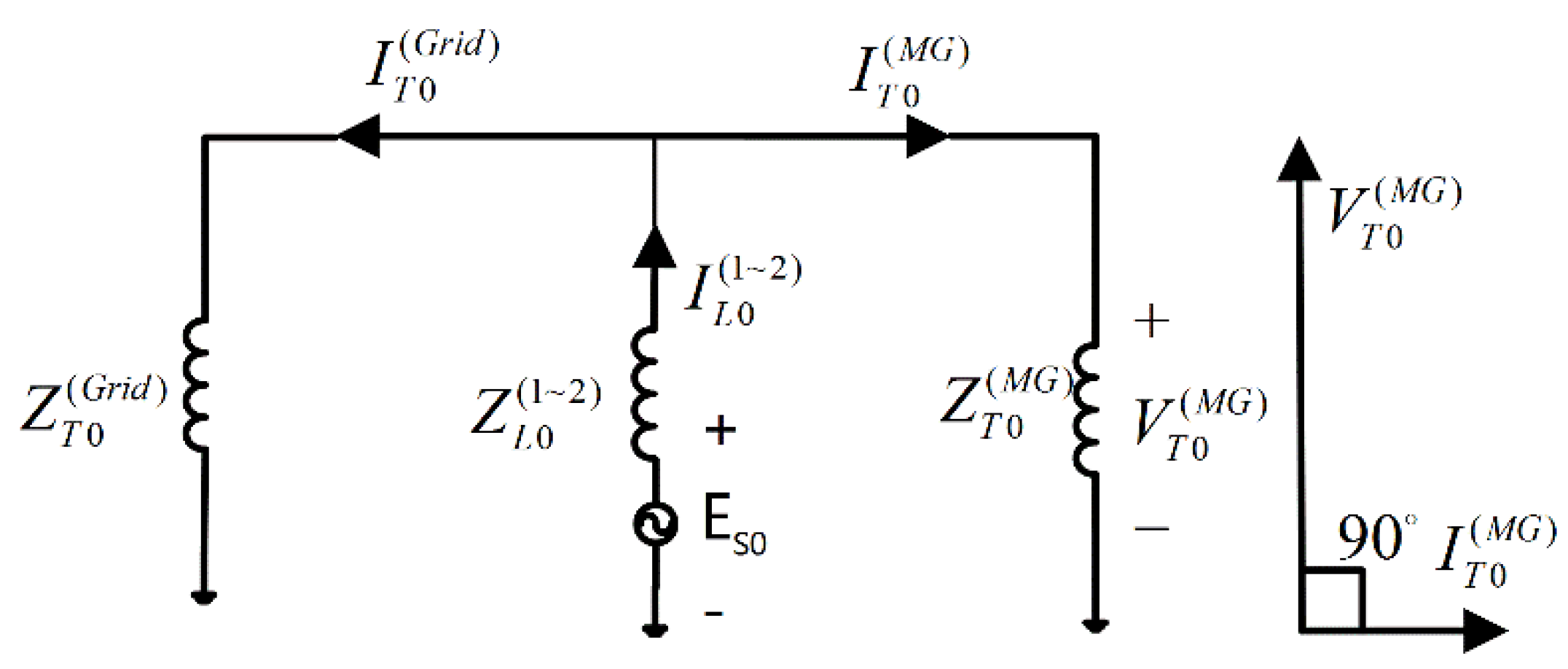
Figure 2 shows a simplified zero-sequence network for the grid SLG fault together with the corresponding phasor diagram. The zero-sequence voltage leads the zero-sequence current by 90° at the primary winding of the microgrid step-down transformer; thus, the zero-sequence angle difference was −90° in the case of a grid fault. The zero-sequence network is described using the following notation:
: Zero-sequence inductive impedance from the node to the node,
: zero-sequence current from the fault position to the grid side transformer,
: zero-sequence current from the fault position to the microgrid step-down transformer,
: zero-sequence voltage at the microgrid step-down transformer primary winding, and
: zero-sequence source at the fault position.
2.2. Microgrid SLG Faults in Grid-Connected Mode
During a microgrid SLG fault, the zero-sequence angle difference drops to between 60° and 90° in the faulty feeder, depending on the size of the CLR of the GPT. With a feeder that is functioning normally, the zero-sequence angle difference is −90°, and the fault section can be identified based on the zero-sequence angle difference. The ZCTs at each feeder, together with the GPT at the PCC bus, can be used to measure the zero-sequence voltage and zero-sequence current in the ungrounded microgrid.
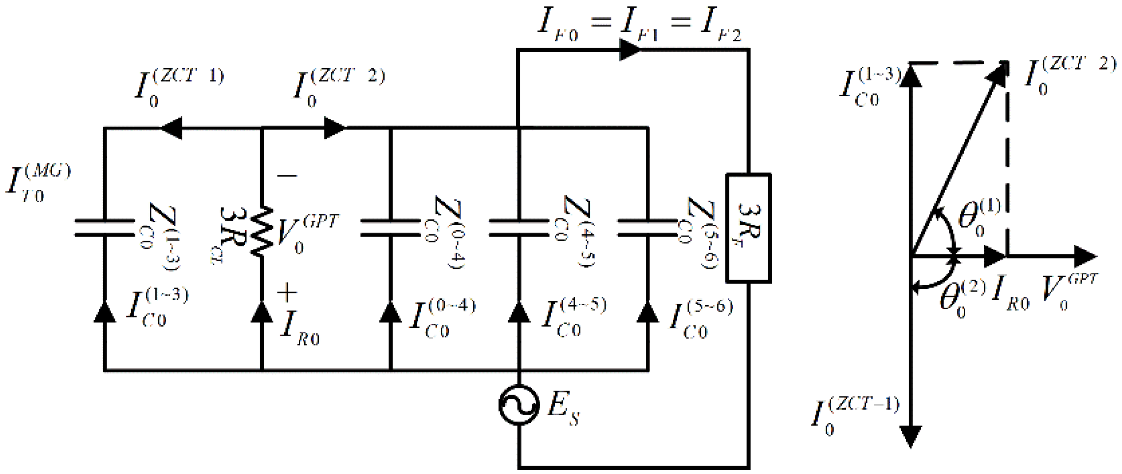
Figure 3 shows simplified zero-sequence networks together with the corresponding phasor diagram for the microgrid, with the faults shown in
Figure 1 using the following notation:
: Zero-sequence capacitive impedance from the node to the node,
: zero-sequence current from the node to the node radially,
: zero-sequence voltage at the node,
: fault current,
: CLR current,
: zero sequence angle difference in the faulty feeder, and
: zero sequence angle difference in the healthy feeder.
Because the magnitude of the zero-sequence impedance of an ungrounded system is large, the positive- and negative-sequence impedances can be ignored when considering SLG faults with no significant loss of accuracy.
When the microgrid fault occurs on the right side of the SWB4, the fault direction can be detected readily, using the angle difference between the zero-sequence voltage angle and zero-sequence current angle, if there is a GPT installed at the load bus of SWB4. The zero-sequence angle difference drops to between 60° and 90° in the fault direction. With a direction that is functioning normally, the zero-sequence angle difference is between −180° and −90°. If there is not a GPT installed at the load bus, the three zero-sequence current angle directions can be compared to indicate the direction of the fault. Angle directions of two zero-sequence currents are similar, while in the other zero-sequence current the angle direction is reversed. The reversed one indicates the direction of the fault.
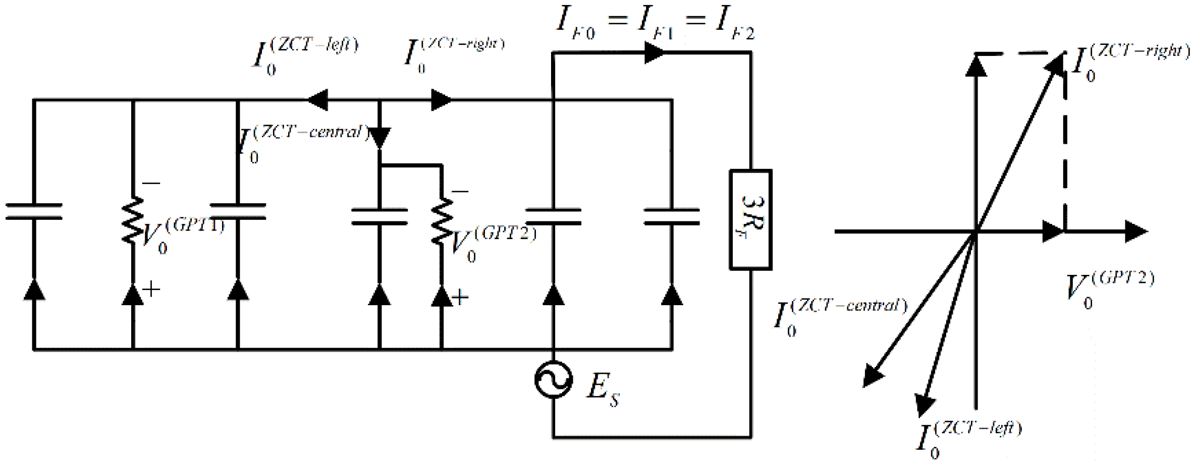
Figure 4 shows simplified zero-sequence networks together with the corresponding phasor diagram for the microgrid. In the case of a microgrid network fault, two SWBs near the fault position can locate the fault section. In the case of a microgrid load fault, the protection installed at the SWB can indicate the fault position itself.
2.3. Microgrid SLG Faults in the Autonomous Mode
The microgrid operates in the autonomous mode when it is intentionally disconnected from the main medium voltage (MV) grid. The fault detection method for microgrid SLG faults is the same in the grid-connected mode and the autonomous mode because of the characteristics of the ungrounded microgrid. In the case of an autonomous microgrid fault, the fault feeder is detected by the zero-sequence voltage at the substation and zero-sequence currents flowing into each feeder. In addition, the fault phase is also readily detected using the phase-to-neutral voltage at the step-down transformer secondary winding. A fault within an autonomous microgrid results in a network-wide voltage drop, which can be used for fault detection. Once both the fault feeder and the fault phase are detected, the fault section can be identified. The CB installed at the end of the feeder and DER connection point can be used to isolate the fault area. The healthy section of the microgrid can be isolated from the fault section to eliminate the fault.
3. Protection Method for SLG Faults
The proposed protection method consists of a computer or microprocessor situated centrally (substation) or locally (switch board) that is able to detect the fault and send a required action at the hardware level.
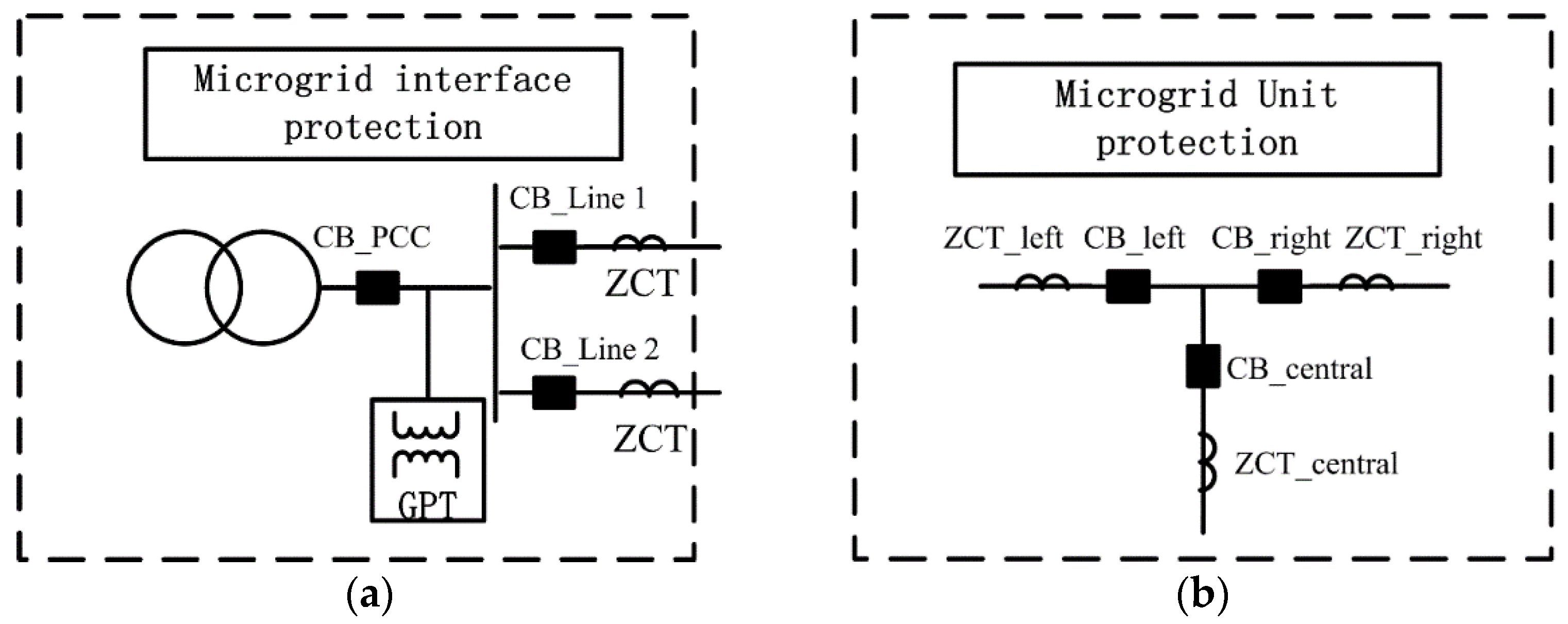
Figure 5a shows the interface protection system installed at the microgrid step-down transformer. The interface protection system can obtain the required information from the primary winding of the step-down transformer, the GPT, and the two ZCTs installed at the end of the feeder. The CB at the PCC bus is controlled by the interface protection, as are the feeder CBs. The two breakers installed at the end of each feeder can be used to isolate the faulty section.
The microgrid unit protection is shown in
Figure 5b. The microgrid unit protection can obtain the required information from three ZCTs installed at the SWB. The microprocessor is situated locally (SWB) and can detect the fault direction and send the information to the microgrid control center.
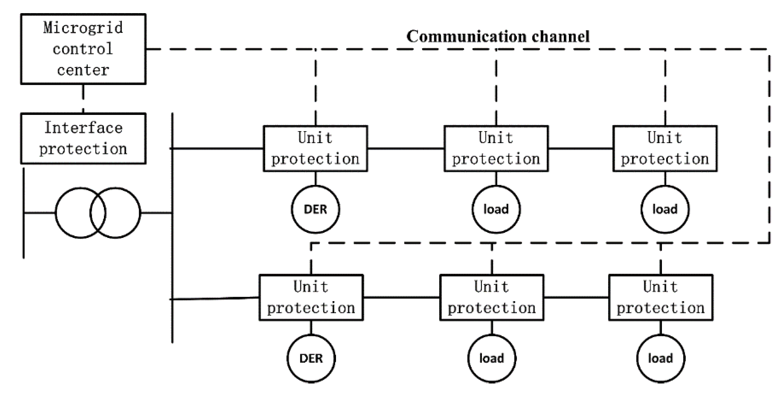
As shown in
Figure 6, there is a microgrid control center and interface protection in the substation. At each SWB, there is microprocessor for unit protection (DER or load). The configuration of the protection system is shown in
Figure 6. Detection and isolation of the fault section can be realized using the protection system. The coordination of interface protection and unit protections can help isolate the smallest fault section. There is a control center to control the microgrid. The fault direction signal is exchanged between the interface protection and unit protections via a communication channel.
We explored three scenarios with regard to fault position and the status of the microgrid:
Grid-connected mode: utility grid SLG fault.
Grid-connected and autonomous modes: microgrid network SLG fault.
Grid-connected and autonomous modes: microgrid load SLG fault.
3.1. Utility Grid SLG Faults
As shown in
Figure 7, when a utility grid SLG fault occurs at the same feeder of microgrid in the grid-connected mode, the CB installed in the microgrid at the PCC point will open to isolate the microgrid. The main grid protection clears the fault. Once the utility grid fault is cleared, the microgrid is resynchronized and reconnected to the utility grid.
3.2. Microgrid Network SLG Faults
As shown in
Figure 8, a microgrid protection should disconnect the smallest possible portion of the microgrid feeder in the case of a microgrid network SLG fault. In the case when an abnormal situation is detected, a tripping condition (measuring ZCT current in a specific direction) is checked by the unit protection. If the tripping condition is reached, a CB will open.
In the case of fault F2, the unit protection installed at SWB4 sees the fault on the right side and CB4.2 will open. If the unit protection installed at SWB5 sees the fault on the left side, CB5.1 will open. CB3.2 and CB6.2 are controlled according to the signal from the microgrid control center. If there is a tie breaker and distribution line between feeder 1 and feeder 2, then SWB5 and SWB6 can be transferred to feeder 1 and resupplied via SWB3. The proposed protection method allows for the selective operation of CBs.
There are two special cases:
- (1)
In the case of fault F1, CB4.1 will open. CB0.2 is controlled by the interface protection. Once the fault F1 is detected by the interface protection, then CB0.2 will open.
- (2)
In the case of fault F3, CB6.1 was designed as a hardware lock with CB5.2 because only two zero-sequence currents can be detected in SWB6. Once the relay at SWB5 detects the downstream network fault, then CB5.2 and CB6.1 are opened. SWB6 will be resupplied via SWB3.
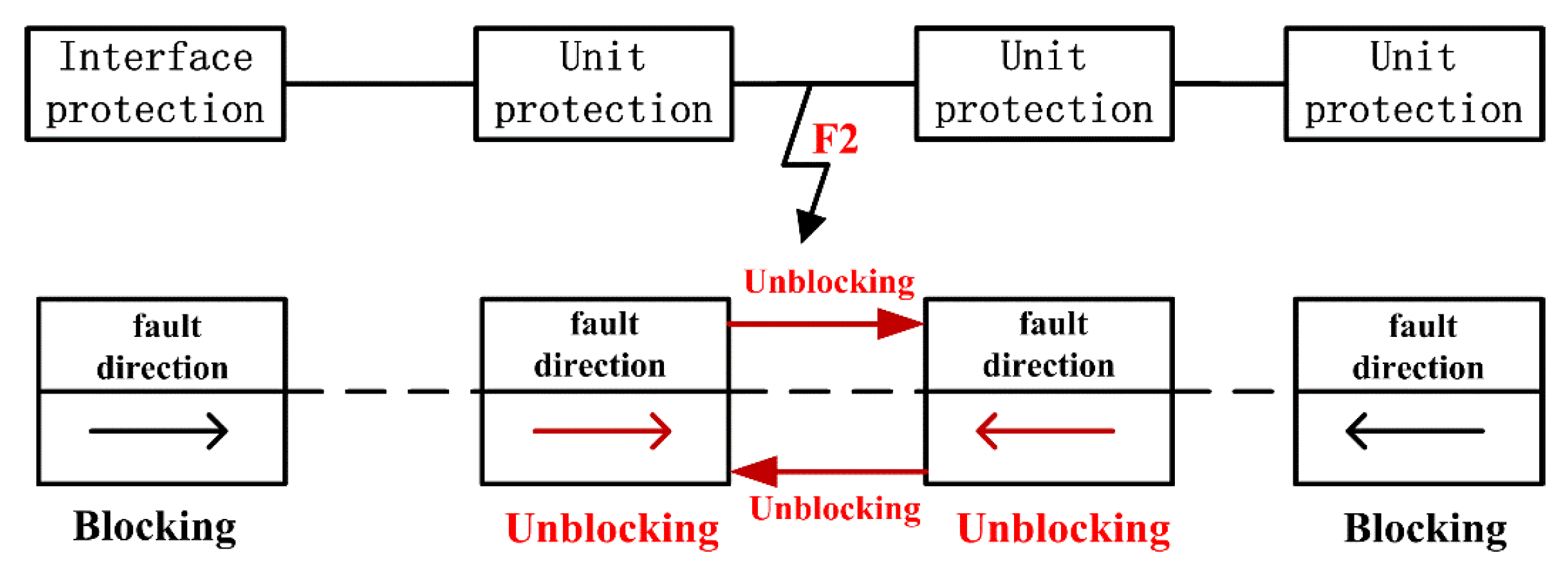
In the case of a microgrid network fault, the unit protections and interface protection will all detect the fault direction. To isolate the smallest section, direction coordination is used. In the case of a fault, each unit protection sends the fault direction signal to its upstream and downstream unit protection. The initialization state of each feeder CB of unit protection is blocking.
As shown in
Figure 9, if the fault direction signal of the unit protection and its upstream/downstream unit protection are different, the unit protection will send an unblocking signal to its upstream/downstream unit protection. If the fault direction signal of the unit protection and its upstream/downstream unit protection are the same, the unit protection unblocking operation will not begin. If the unit protection is unblocked, it will issue a trip command to the feeder CB of the local SWB.
3.3. Microgrid Load SLG Faults
As shown in
Figure 10, the unit protection will send a trip signal to the central breaker of the SWB in the case of a microgrid load fault. Once the load fault is detected, the load bus should be isolated from the microgrid. The other parts of the microgrid keep working. The DER connected to this bus is cut off. Once the fault is cleared, the load and DER can be reconnected to the microgrid.
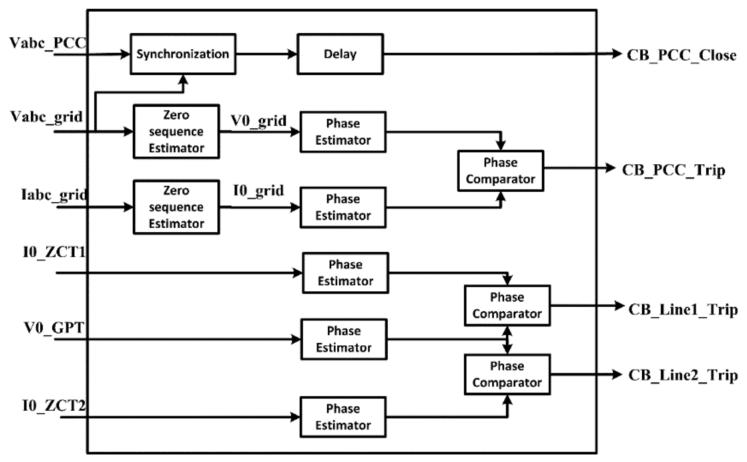
Figure 11 shows a simplified block diagram of the interface protection system, including the functional modules. The protection system consists of a grid fault detection module, a microgrid fault detection module, and a microgrid reconnection decision module. The protection system is based on zero-sequence components. At the primary winding of the step-down transformer, a zero-sequence estimator was used to determine the zero-sequence voltage and the zero-sequence current. At the secondary winding of the step-down transformer, the zero-sequence voltage and current can be obtained directly from the GPT and the ZCT.
In the grid-connected mode, the phase comparator will calculate the difference between the zero-sequence grid voltage angle and the zero-sequence grid current angle. A synchronism module will enable safe reconnection to the utility grid after the utility grid fault is cleared. If there is an SLG fault in the microgrid, the protection system will detect the faulty section and the faulty phase. If the angle difference exceeds the threshold for a certain time period, the protection issues a trip command;
i.e.,
where
is the zero-sequence angle difference and
is the threshold angle difference. The threshold value for a grid fault can be set at 80° (where voltage leads the current). The threshold for a microgrid fault can be set at 60° (where current leads the voltage).
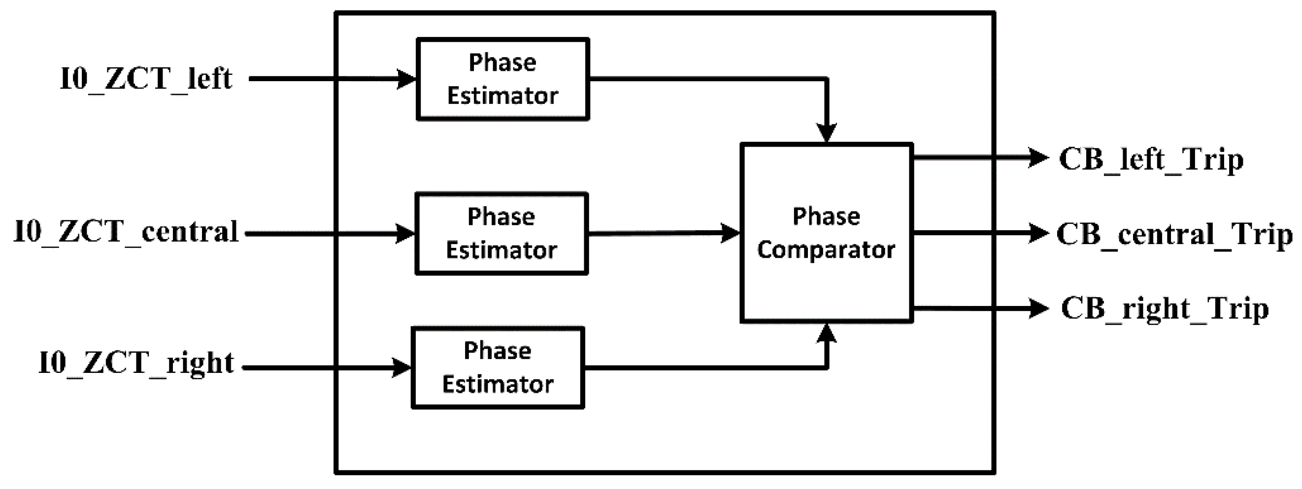
Figure 12 shows a simplified block diagram of the unit protection. The zero-sequence current can be obtained directly from the ZCTs. The protection can indicate the direction of the fault by comparing the zero-sequence current directions. The directions of two zero-sequence currents are similar while the other zero-sequence current angle direction is reversed. The reversed one indicates the fault direction.
Since the proposed method relies on communication signals, communication failure is critical to protect the microgrid. To cope with a communication failure, a backup protection should be considered. Interface protection will be operated after a given time, as a backup protection in case that there is a communication failure. Using this method, the protection system can protect the microgrid in both grid-connected and autonomous modes without changing the protection scheme.
4. Case Study
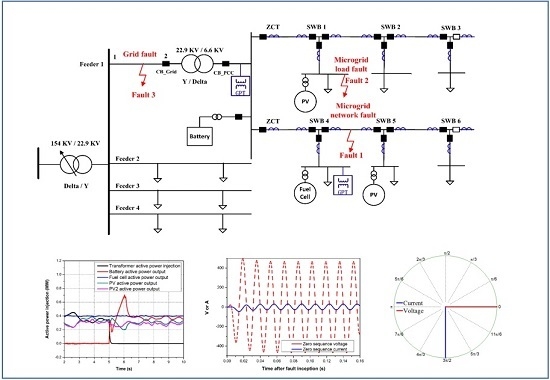
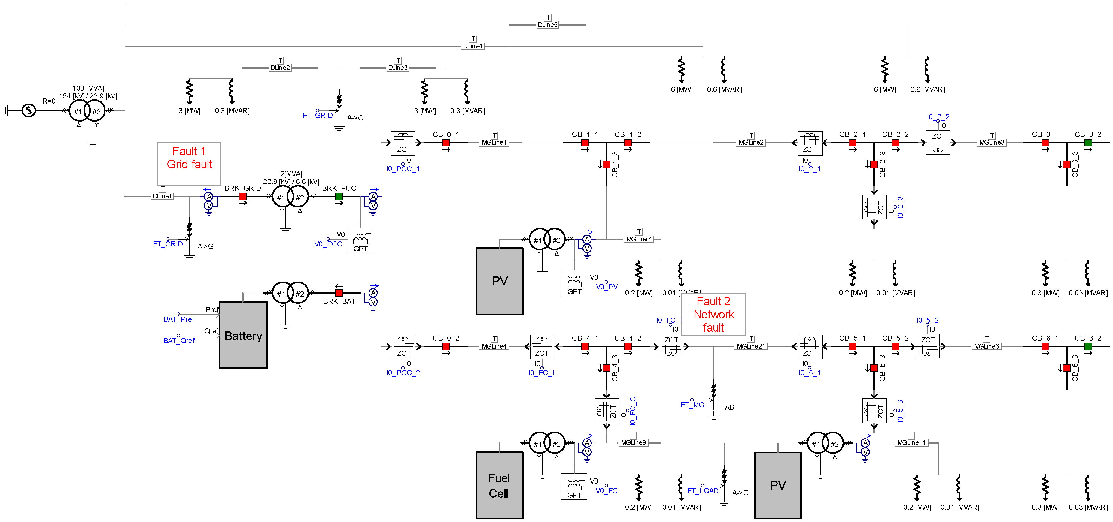
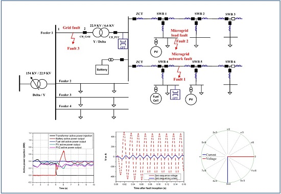
To investigate the effectiveness of the protection method, a low-inertia microgrid was simulated using Power System Computer Aided Design (PSCAD)/Electromagnetic Transients including DC (EMTDC), as shown in
Figure 13. The grid was represented by a 154-kV bus with a short-circuit capacity of 100 MVA. The distribution grid had four feeders, where each supplied a 6.02 MW load (PF 0.99). At feeder 4, there was a step-down transformer for a microgrid. In the microgrid, four DERs were connected to the system. The battery, two PV bus, and fuel cell were all inverter-based DERs.
The parameters of the study microgrid are shown in
Table 1. The distribution line was 1 km between different unit protections.
Table 2 gives the distribution line parameters used in the simulations.
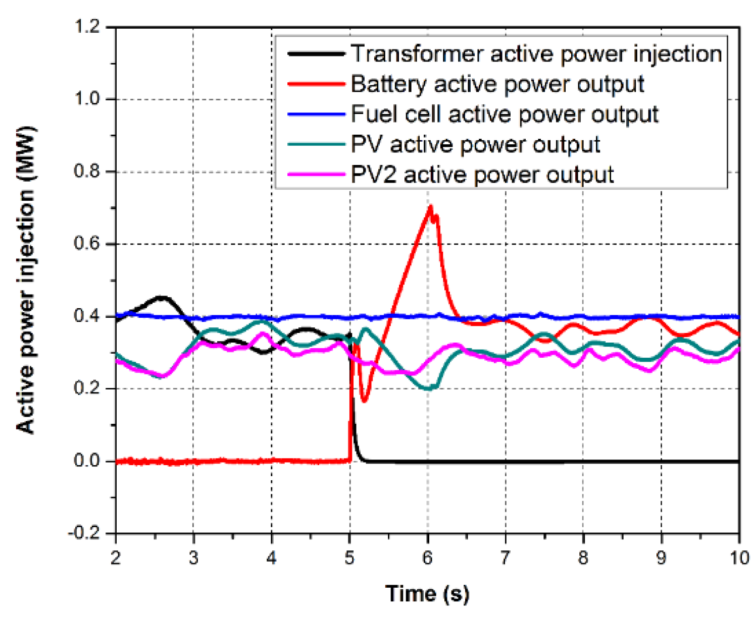
Figure 14 shows the simulation results. In grid-connected mode, the battery shuts down, but the two PV DERs and the fuel cell DER continued to operate in active-reactive power (P-Q) control mode [
26,
27,
28,
29]. When operation of the microgrid changed from grid-connected to autonomous mode at 5 s, the battery DER discharged to maintain power balance in the microgrid [
30,
31,
32,
33]. The voltage and frequency of the microgrid were regulated using droop control. The simulation results show that the microgrid worked well in both conditions [
34,
35,
36].
The voltage and current signals were pre-conditioned using a second-order Butterworth low-pass filter, and a discrete Fourier transform (DFT) was used to estimate the phasors [
37,
38]. As shown in
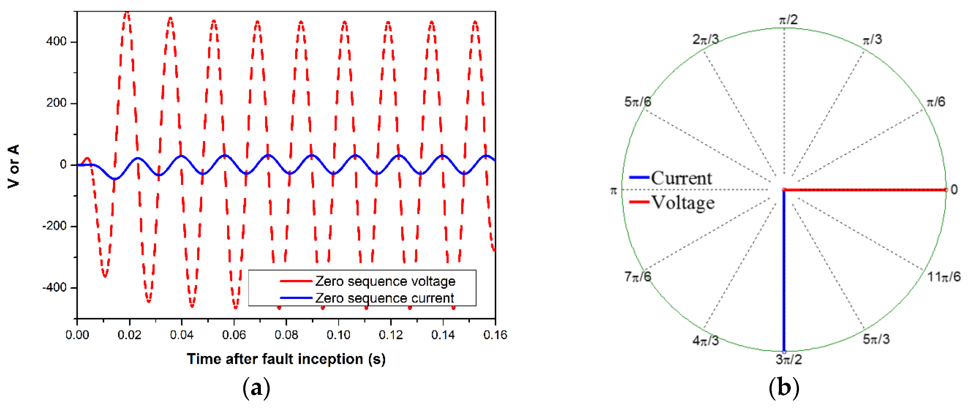
Figure 15, the zero-sequence-voltage and zero-sequence current at the primary winding of the step-down transformer indicated that a grid fault occurred at position 1. Under fault operating conditions, the zero-sequence voltage leads the zero-sequence current by 90°; the grid fault was detected using the angle difference.
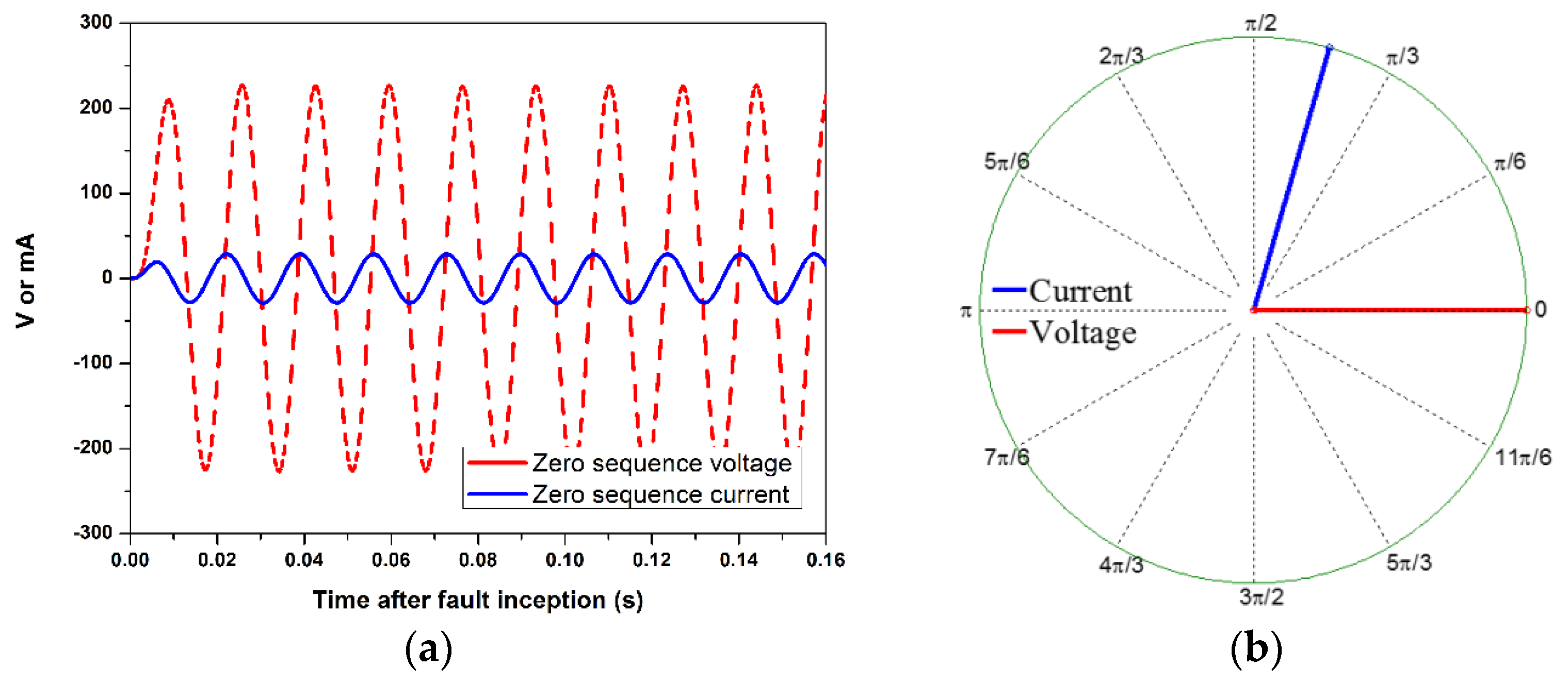
With a microgrid fault at the position 2, as shown in
Figure 13, the zero-sequence current at feeder 2 led the zero-sequence voltage at the PCC bus, as shown in
Figure 16. The zero-sequence angle difference dropped to between 60° and 90° in feeder 1. The angle difference indicated that there was an SLG fault at feeder 1.
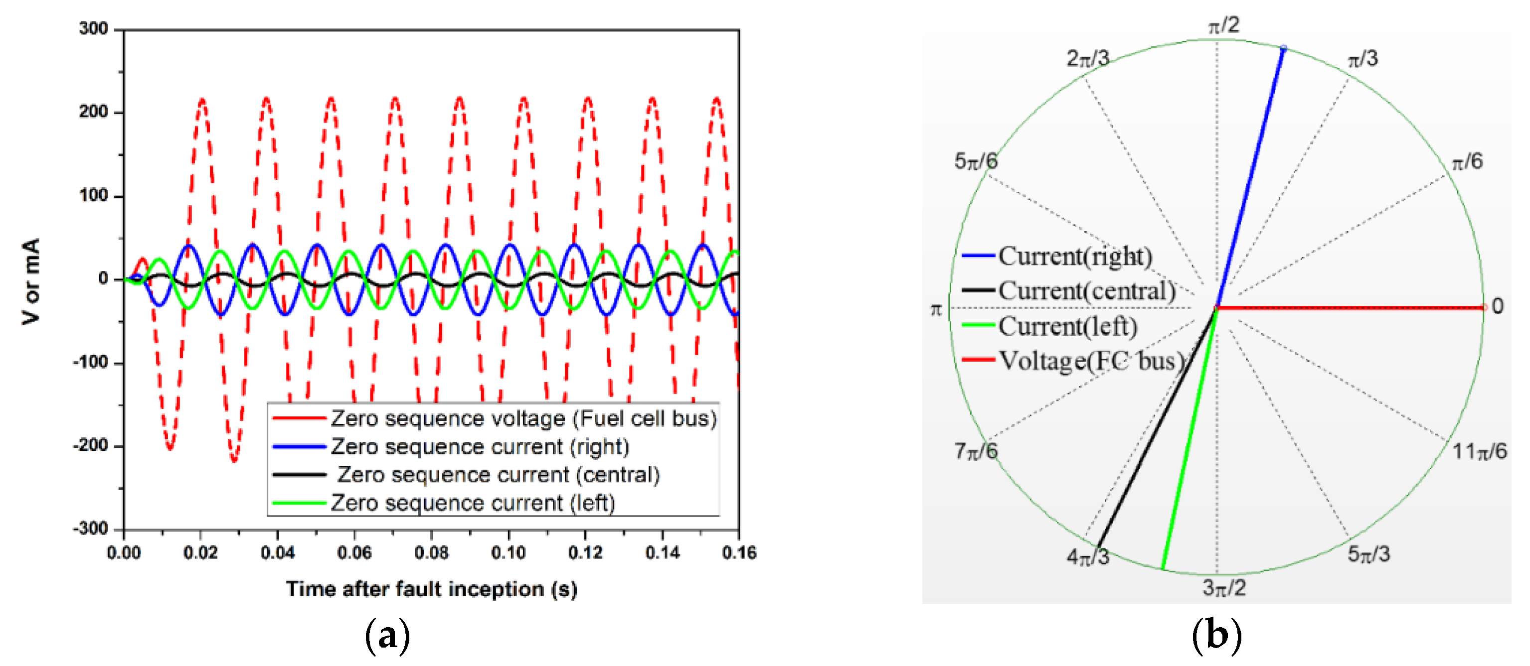
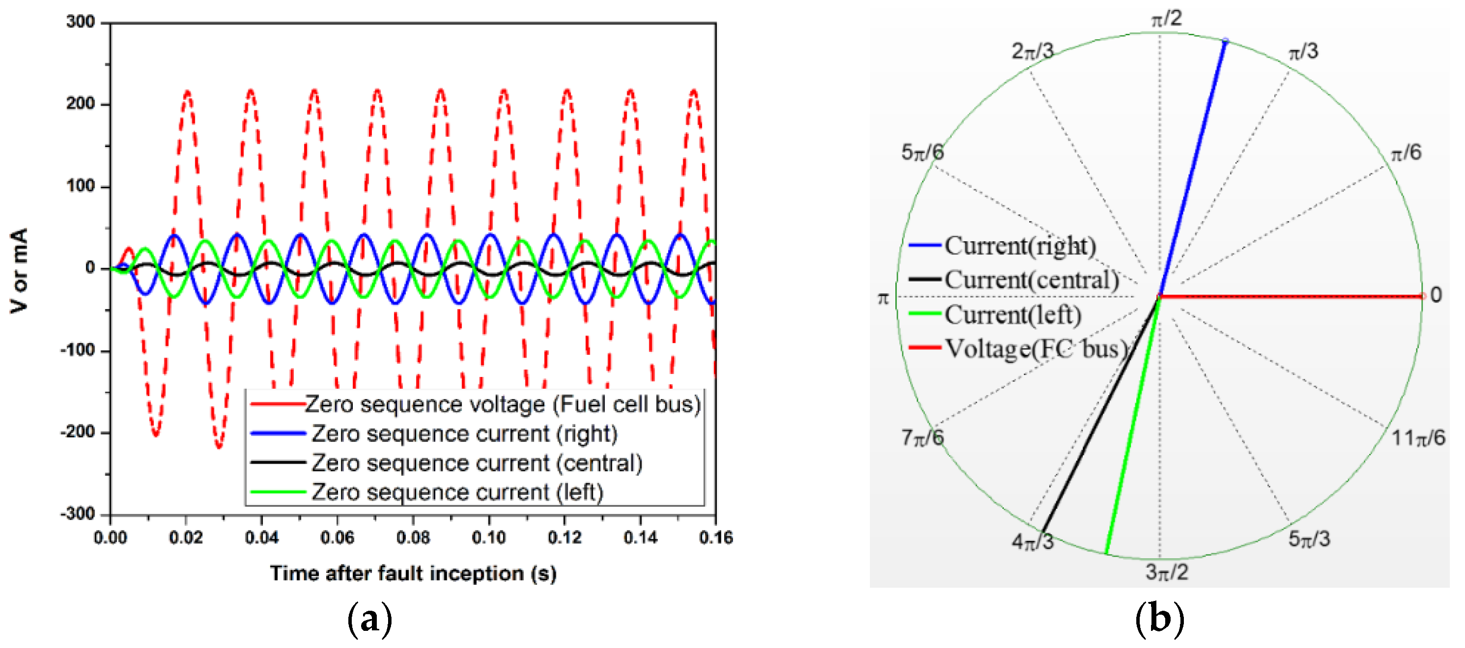
When a microgrid network fault occurred at position 2, as shown in
Figure 13, the zero-sequence currents and the zero-sequence voltage at the SWB4 are shown in
Figure 17. The fault direction can be detected by comparing the angle difference between the zero-sequence voltage and zero-sequence current. The zero-sequence angle difference between the voltage and current dropped to between 60° and 90° in the fault direction. If there is no GPT installed at the load bus, the fault direction can be detected by comparing the three ZCTs’ zero-sequence current angle direction. The angle direction of two ZCTs’ zero-sequence currents are the same, while the other ZCT’s zero-sequence current angle direction is reversed. The reversed one indicates the fault direction. The fault section can be detected with the coordination of unit protections.
The high-impedance faults were simulated with a fault resistance of 100 Ω at position 2. The simulation results are shown in
Figure 18.
The fault location is shown in
Figure 19. The fault distance varies from 0.2 KM to 0.8 KM from SWB4.
Table 3 gives the simulation results for faults in different positions. In the table, the left-central means the angle difference between the zero-sequence current measured by left ZCT and central ZCT.
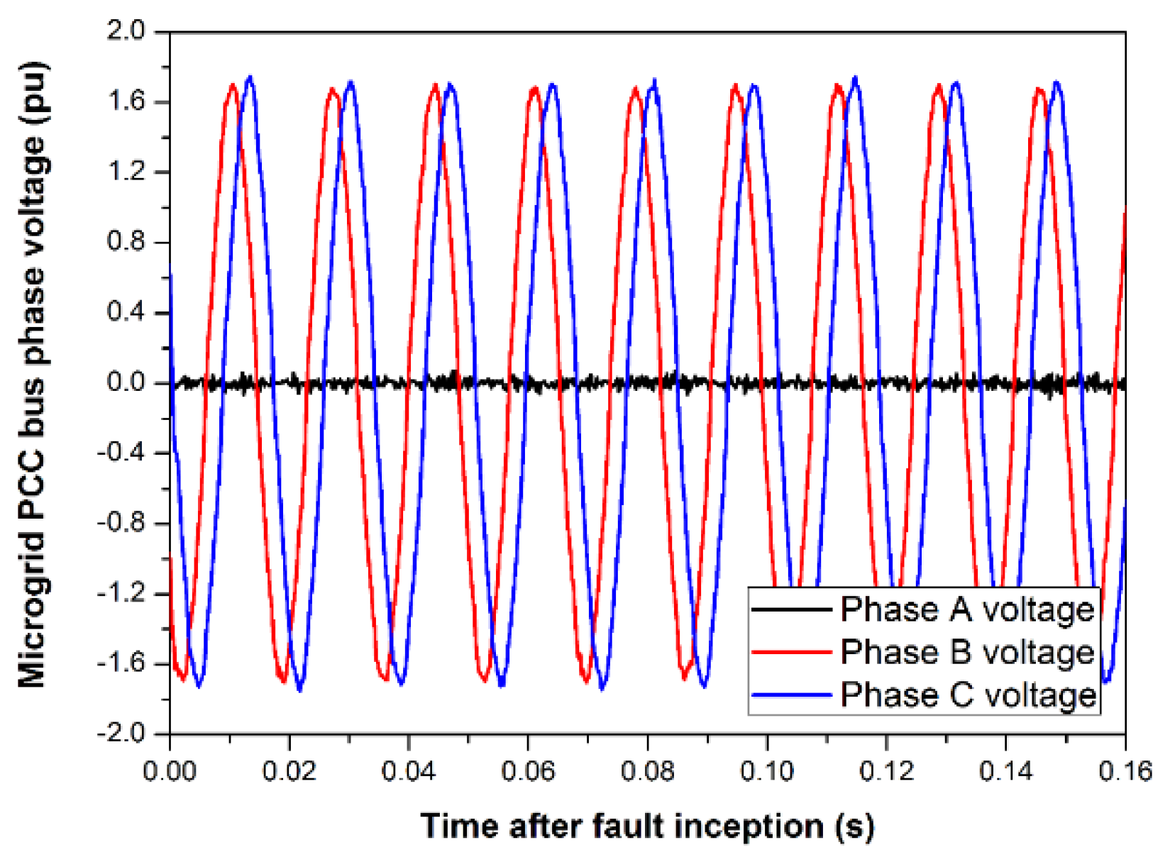
In autonomous mode, the faulty phase may be detected readily using the PCC bus voltage. As shown in
Figure 20, the A phase-to-neutral voltage was almost zero during the fault. This clearly shows that the faulty phase is phase A.
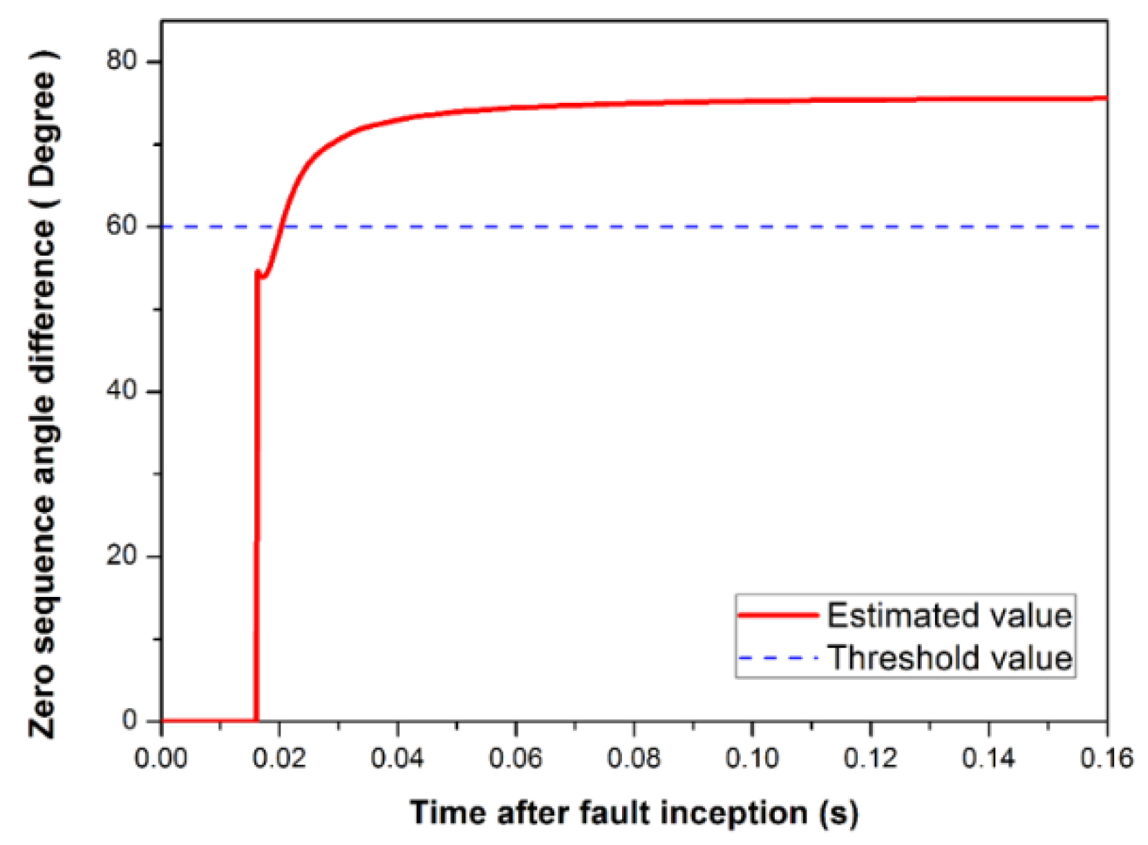
Figure 21 shows the estimated angle difference during a microgrid fault. At 0.02 s after the fault began, the protection system detected the fault and sent a trip signal to the CB at feeder 2. One of the merits of ungrounded systems is that they continue to be operated even though SLG faults occur in them. Although fast detection is preferred for safety, detection time of SLG faults may be non-critical in the ungrounded systems.
5. Conclusions
We have described a novel protection method for ungrounded low-inertia microgrids in both autonomous and grid-connected modes. The proposed protection system can respond to both grid SLG faults and microgrid SLG faults. The microgrid interface protection is based on the difference between the zero-sequence voltage angle and the zero-sequence current angle at the microgrid interconnection transformer. The microgrid unit protection is based on a comparison of the three zero-sequence current phase directions at each junction point of load or distributed energy resources. The technique consists of a fault detection method and a method to identify the faulty section during microgrid SLG faults. The fault section location technology operates according to the coordination of microgrid unit protection. In modern power systems including microgrids, protective Intelligent Electronic Devices (IEDs) are usually equipped with communication functionality, such as the International Electrotechnical Commission (IEC) 61850. Therefore, we think that there is no more additional cost except the costs of GPTs and ZCTs. The low-inertia microgrid model and the relay were simulated using PSCAD/EMTDC, and the results showed that the proposed method can detect SLG faults in both modes, as well as identify the faulty phase in the case of microgrid SLG faults. In this paper, SLG faults are studied. In the future, protection methods for line-to-line, line-to-line-to-ground, and three-phase faults will be developed, and an ungrounded low-inertia microgrid will be implemented on a real-time digital simulator for evaluating the whole protection methods.


