
Evaluation of Strategies to Improve the Thermal Performance of Steel Frames in Curtain Wall Systems


Abstract
:1. Introduction
2. Evaluation Method and Validation
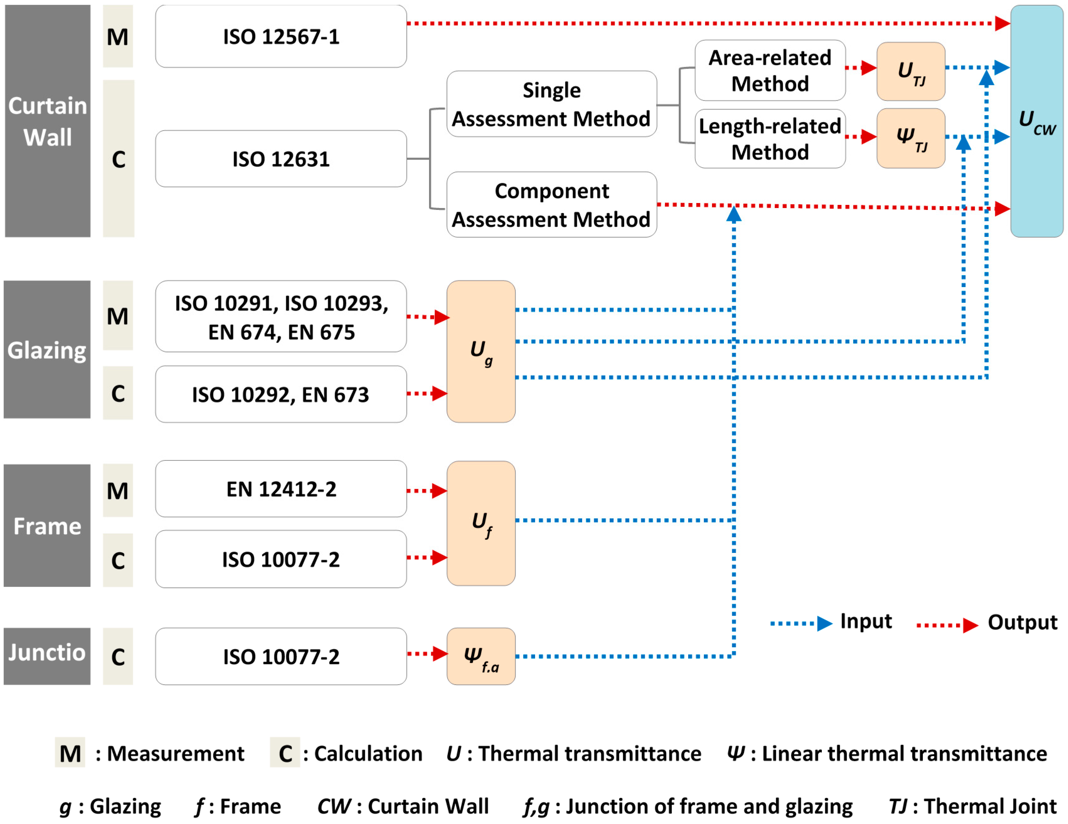
2.1. Overview of Standards for Evaluating the Thermal Performance of Curtain Walls
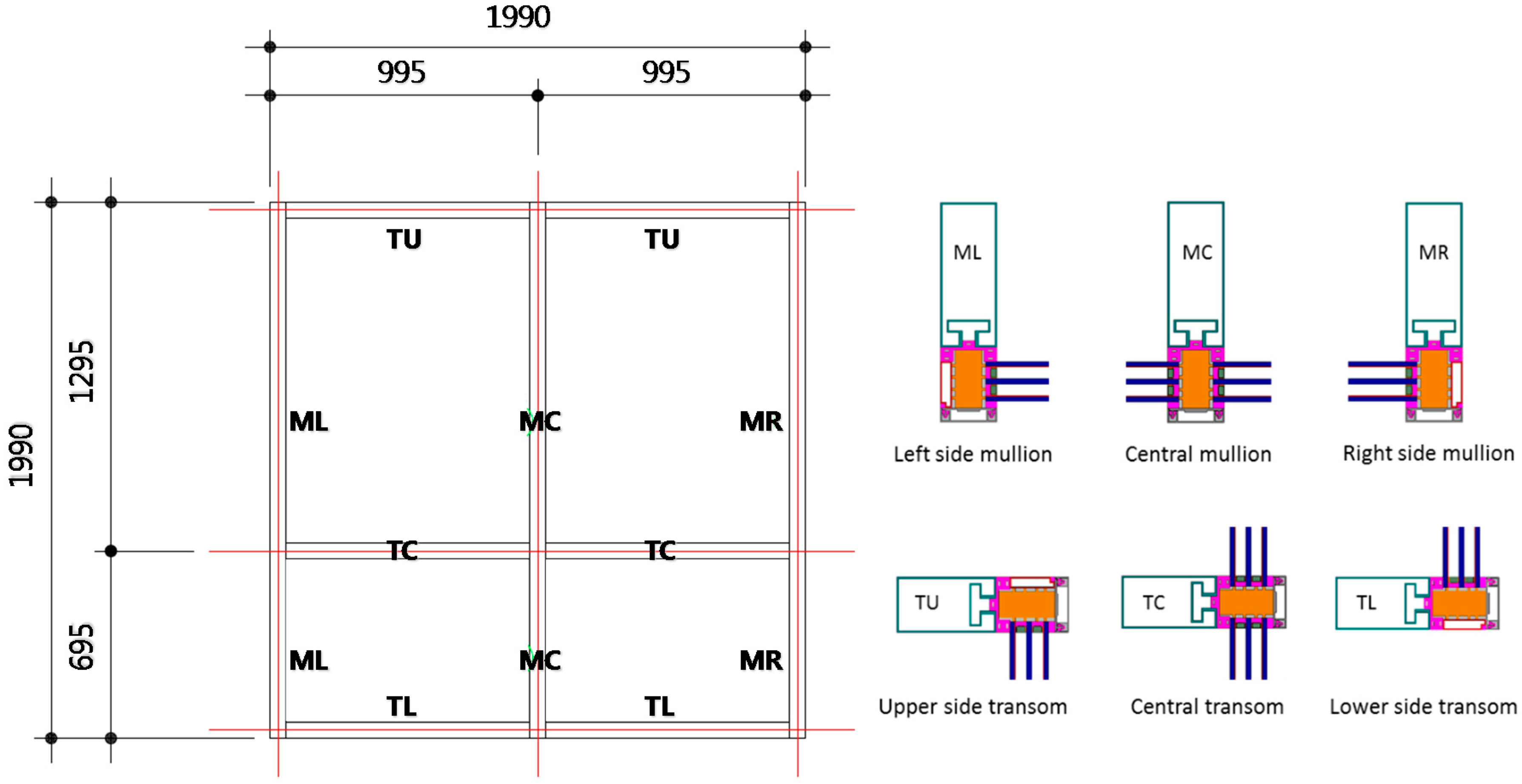
2.2. Calculation Method and Validation
3. Evaluation Cases Setup
4. Results and Discussion
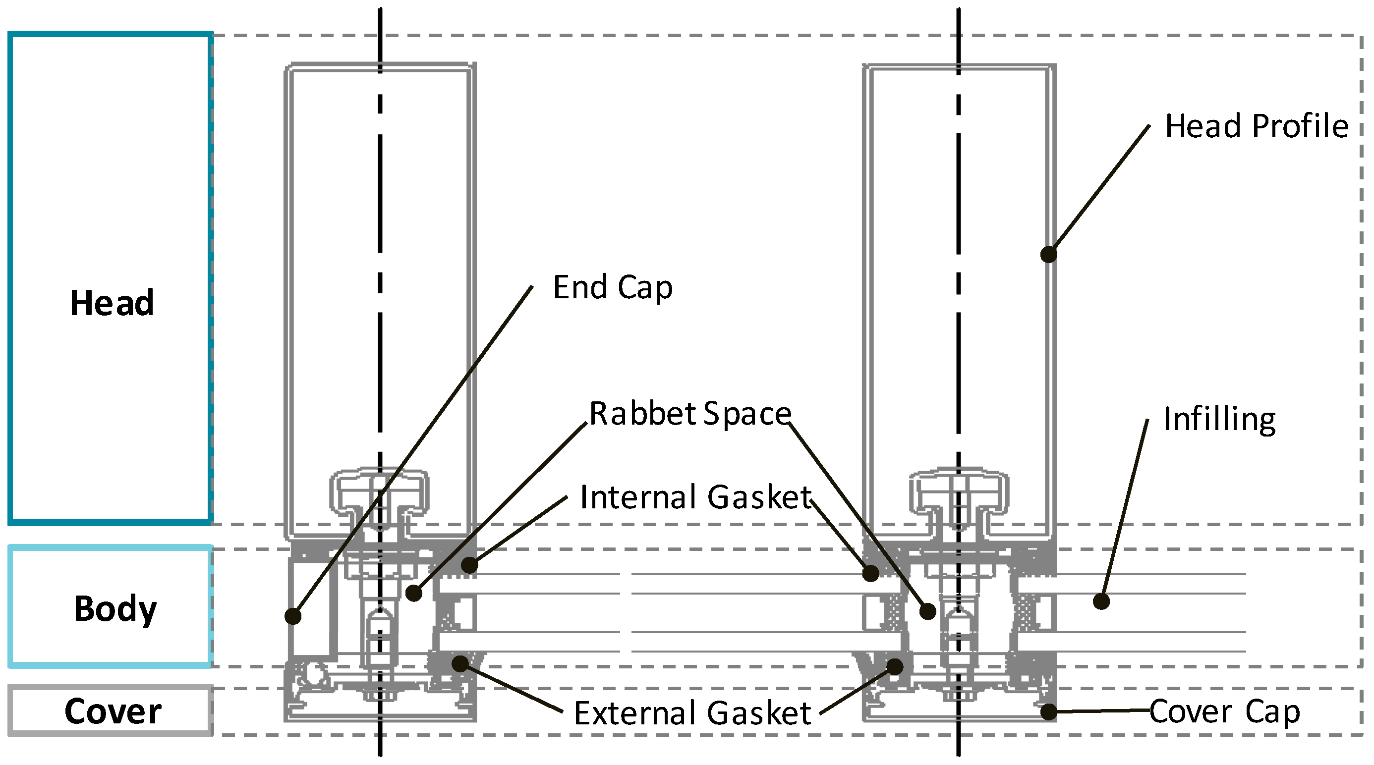
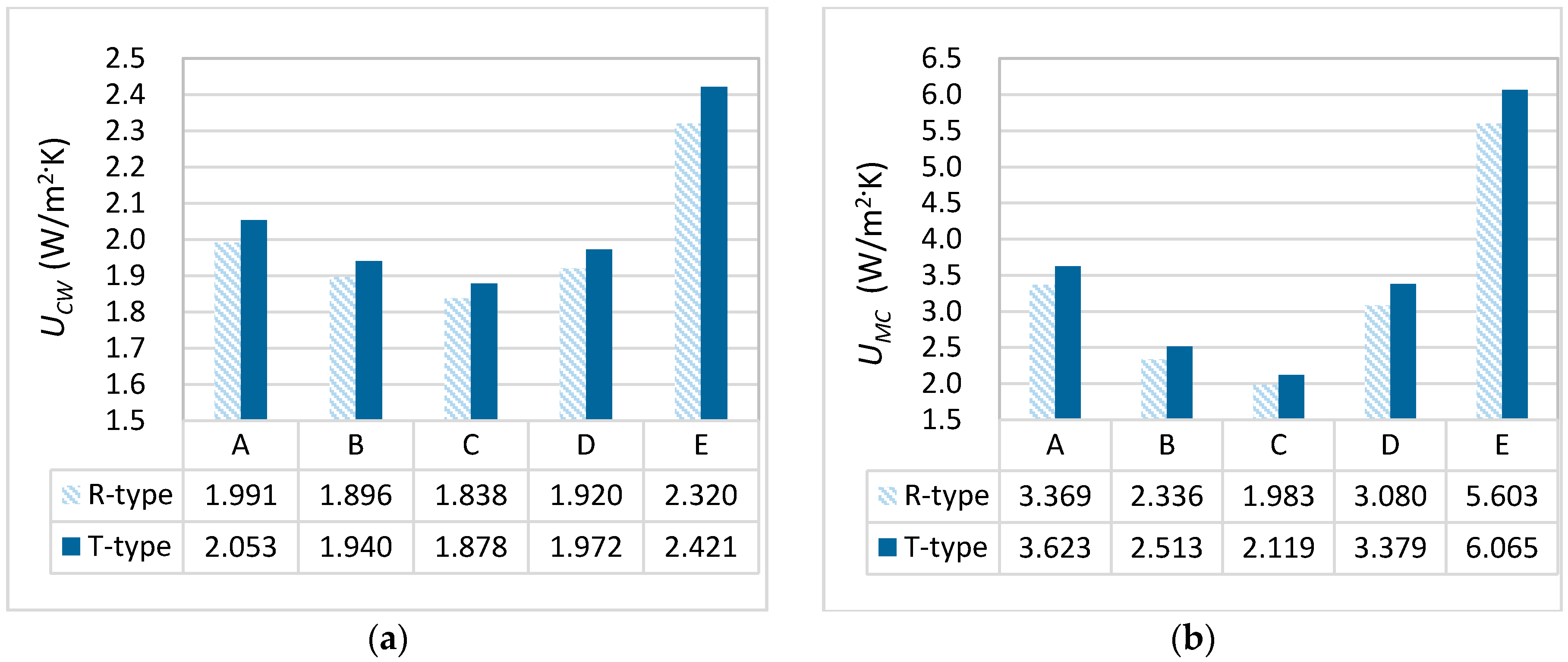
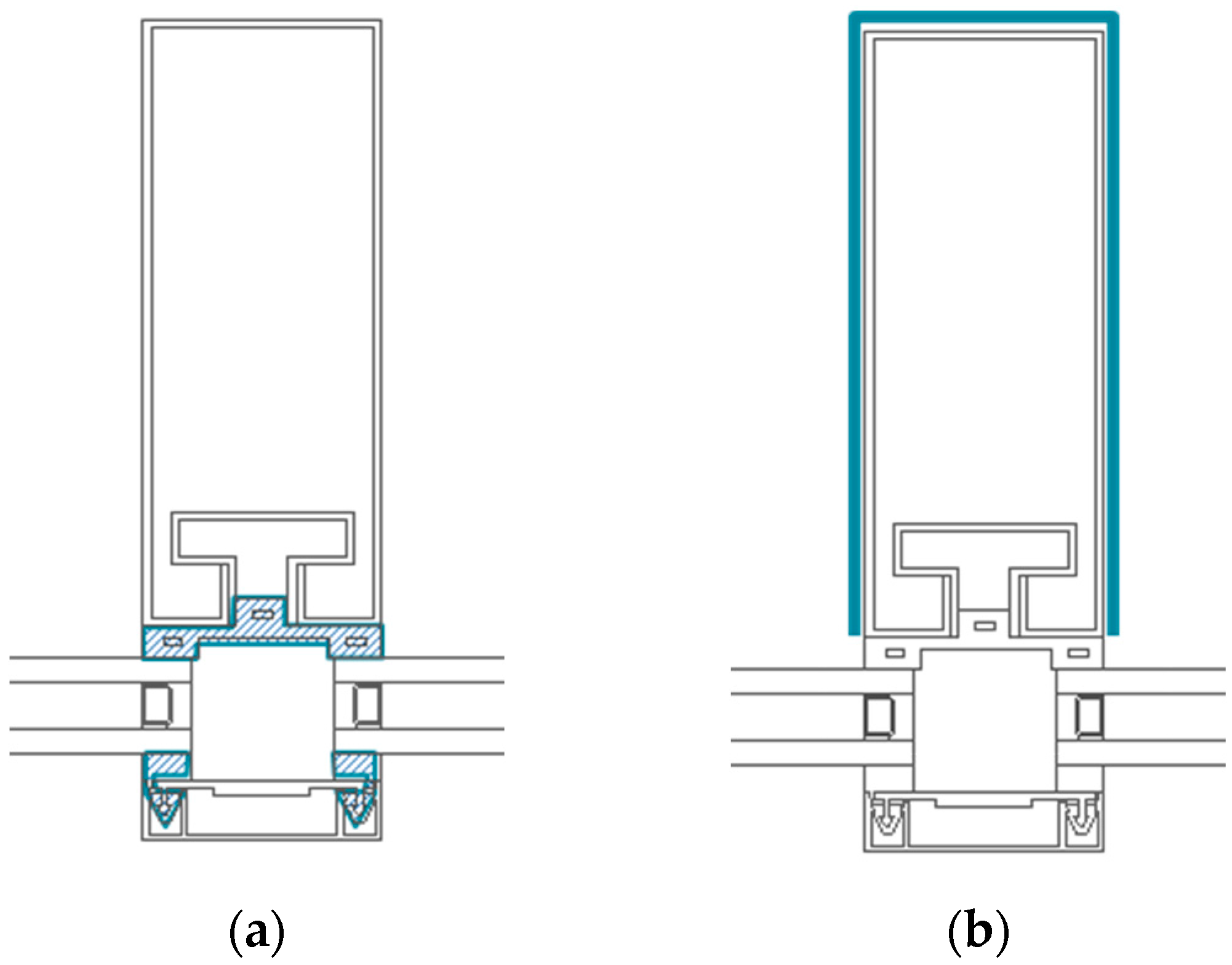
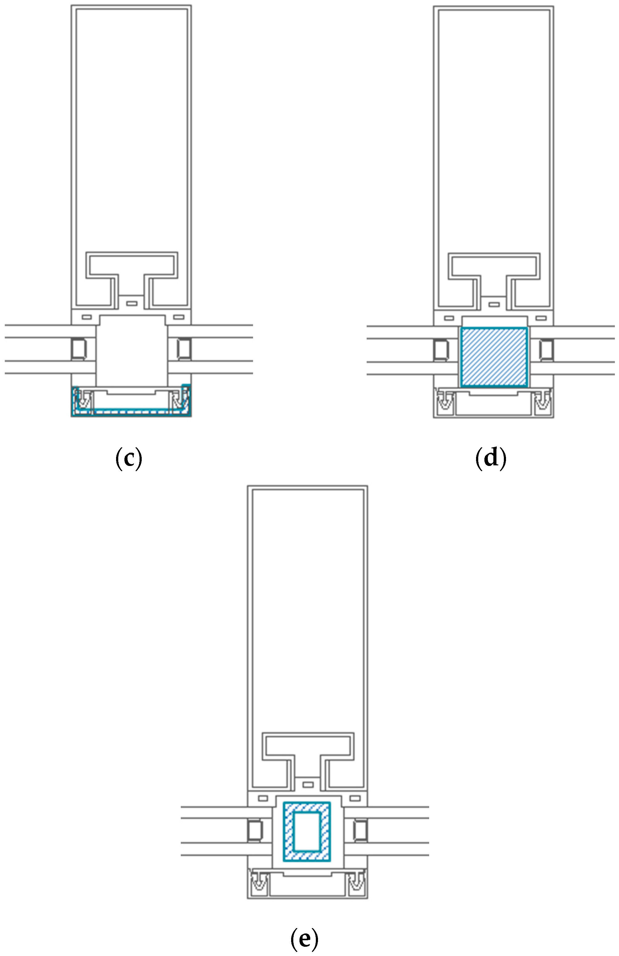
4.1. Comparison According to the Head Profile Shape and Rabbet Space Details
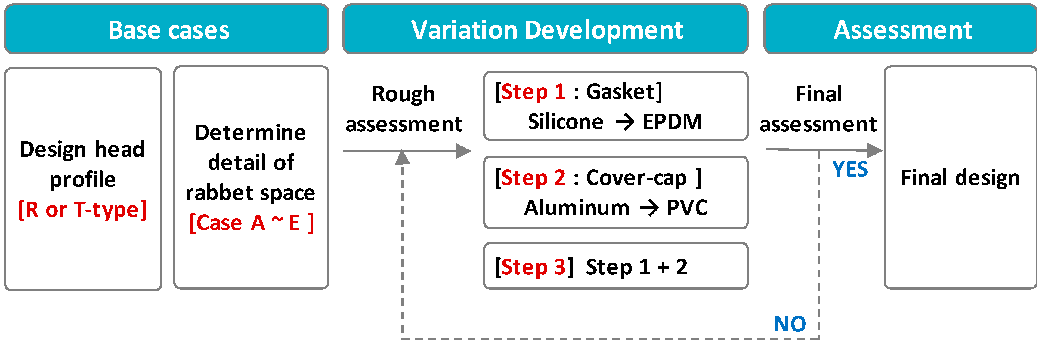
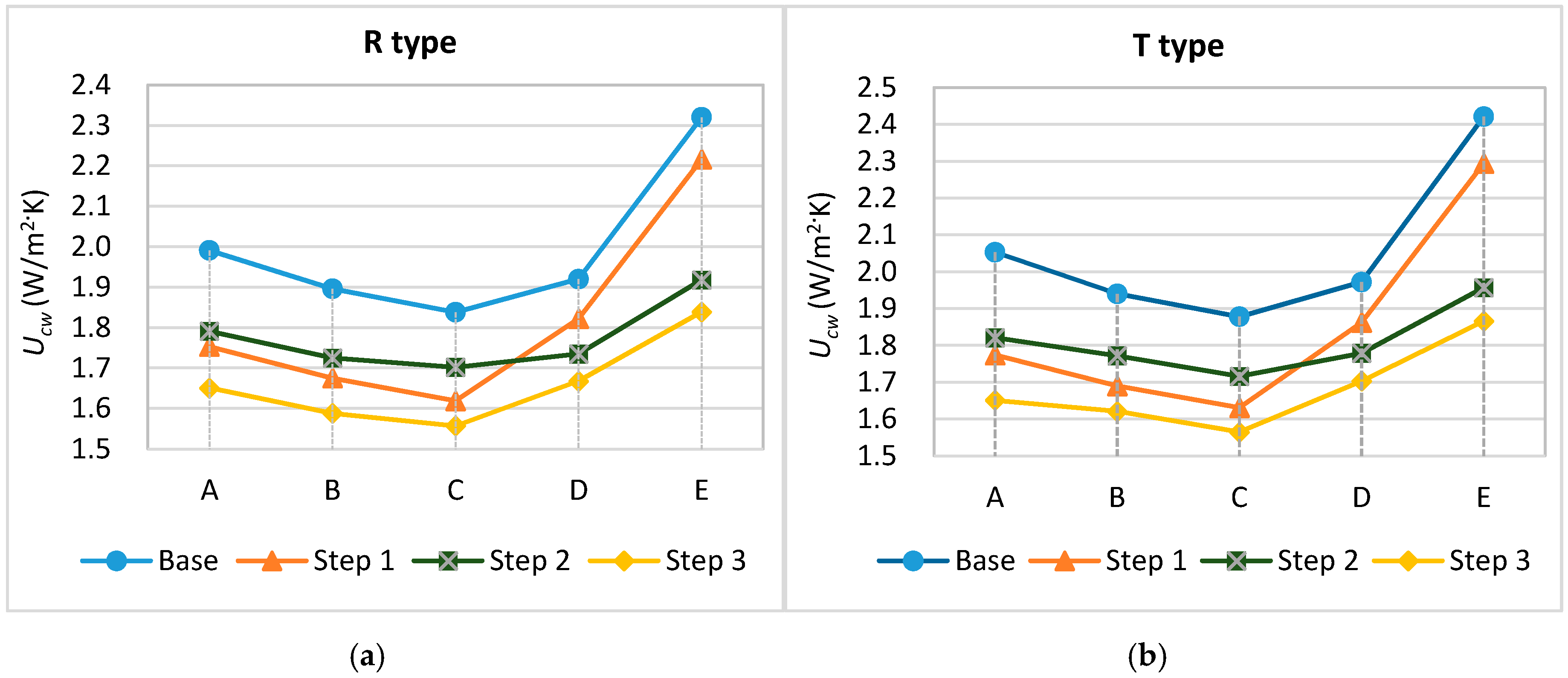
4.2. Comparison of Thermal Transmittances According to the Gasket and Cover Cap Materials
5. Conclusions
Acknowledgments
Author Contributions
Conflicts of Interest
References
- Yoo, H.J.; Yang, S.W.; Kim, S.S. Comparison of Thermal Transmittances of Curtain Walls by Different Ratio of the Frame Area. In Proceedings of the 11th REHVA World Congress Clima 2013—Energy Efficient, Smart and Healthy Buildings, Prague, Czech Republic, 16–19 June 2013.
- No, S.T.; Kim, K.S.; Jung, J.S. Simulation and mock-up tests of thermal performance of curtain walls. Energy Build. 2008, 40, 1135–1144. [Google Scholar] [CrossRef]
- Cuce, E.; Riffat, S.B.; Young, C. Thermal insulation, power generation, lighting and energy saving performance of heat insulation solar glass as a curtain wall application in Taiwan: A comparative experimental study. Energy Convers. Manag. 2015, 96, 31–38. [Google Scholar] [CrossRef]
- Ilter, E.; Tavil, A.; Celik, O.C. Full-scale performance testing and evaluation of unitized curtain walls. J. Facade Des. Eng. 2015, 3, 39–47. [Google Scholar] [CrossRef]
- Ge, H. Study on Overall Thermal Performance of Metal Curtain Walls. Ph.D. Thesis, Concordia University, Montreal, QC, Canada, 2002. [Google Scholar]
- Song, Y.W.; Park, J.C.; Chung, M.H.; Choi, B.D.; Park, J.H. Thermal performance evaluation of curtain wall frame types. J. Asian Archit. Build. Eng. 2013, 12, 157–163. [Google Scholar] [CrossRef]
- Ge, H.; Fazio, P. Evaluation of critical factors affecting the thermal performance of metal curtain walls by simulations. In Proceedings of the International Building Performance Simulation Association Regional Conference 2002, Montreal, QC, Canada, 11–13 September 2002; pp. 112–119.
- Cordero, B.; Overend, M.; Gracia-Santos, A. Thermal performance of novel frame-integrated unitised curtain wall. Rev. Constr. 2015, 14, 23–31. [Google Scholar] [CrossRef]
- Song, J.H.; Lim, J.H.; Song, S.Y. Evaluation of alternatives for reducing thermal bridges in metal panel curtain wall systems. Energy Build. 2016, 127, 138–158. [Google Scholar] [CrossRef]
- Knickerbocker, C. Advanced Steel Framing Emerges for Demanding Curtain Wall Applications, Structure Magazine. 2011. Available online: http://www.structuremag.org/wp-content/uploads/2014/08/C-BuildingBlocks-Knickerbocker-Nov111.pdf (accessed on 26 September 2016).
- International Standard Organization (ISO). ISO 12567-1, Thermal Performance of Windows and Doors—Determination of Thermal Transmittance by the Hot-Box Method—Part 1: Complete Windows and Doors; International Standard Organization: Geneva, Switzerland, 2010. [Google Scholar]
- ASTM International. ASTM C1199-09: Standard Test Method for Measuring the Steady-State Thermal Transmittance of Fenestration Systems Using Hot Box Methods; American Society for Testing and Materials: West Conshohocken, PA, USA, 2009. [Google Scholar]
- American Architectural Manufacturers Association (AAMA). AAMA 1503-09, Voluntary Test Method for Thermal Transmittance and Condensation Resistance of Windows, Doors, and Glazed Wall Sections; American Architectural Manufacturers Association: Schaumburg, IL, USA, 2009. [Google Scholar]
- National Fenestration Rating Council (NFRC). NFRC 102, Procedure for Measuring the Steady-State Thermal Transmittance of Fenestration Systems; National Fenestration Rating Council: Greenbelt, MD, USA, 2010. [Google Scholar]
- Korean Agency for Technology and Standards (KATS). KS F 2278, Test Method of Thermal Resistance for Windows and Doors; Korean Agency for Technology and Standards: Chungbuk, Korea, 2008. [Google Scholar]
- Kim, S.S.; Yim, H.C. Evaluation of the thermal transmittance of curtain walls according to EN 13947. J. Archit. Inst. Korea 2012, 28, 401–408. [Google Scholar]
- International Standard Organization (ISO). ISO 15099, Thermal Performance of Windows, Doors and Shading Devices-Detailed Calculations; International Standard Organization: Geneva, Switzerland, 2003. [Google Scholar]
- International Standard Organization (ISO). ISO 10077-1:2006, Thermal Performance of Windows, Doors and Shutters—Calculation of thermal Transmittance—Part 1: General; International Standard Organization: Geneva, Switzerland, 2006. [Google Scholar]
- International Standard Organization (ISO). ISO 10077-2, Thermal Performance of Windows, Doors and Shutters—Calculation of Thermal Transmittance—Part 2: Numerical Method for Frames; International Standard Organization: Geneva, Switzerland, 2012. [Google Scholar]
- International Standard Organization (ISO). ISO 12631, Thermal Performance of Curtain Walling—Calculation of Thermal Transmittance; International Standard Organization: Geneva, Switzerland, 2012. [Google Scholar]
- International Standard Organization (ISO). ISO 10211, Thermal Bridges in Building Construction—Heat Flows and Surface Temperatures—Detailed Calculations; International Standard Organization: Geneva, Switzerland, 2007. [Google Scholar]
- Foster Profile. Available online: http://www.forster-profile.ch/en/downloads.html (accessed on 26 September 2016).
- METRA Windows and Doors. Available online: http://www.metra.it/building/EN/facciate-continue-in-alluminio-7.aspx (accessed on 26 September 2016).
- RAICO Bautechnik GmbH. Available online: http://www.raico.de/de/Download.php (accessed on 26 September 2016).
- STABALUX: Curtain-Wall and Roof-Glazing. Available online: https://www.stabalux.com/en/curtain-wall-roof-glazing-steel/ (accessed on 26 September 2016).
- REHAU UK: Unlimited Polymer Solutions. Available online: https://www.rehau.com/gb-en/downloads/784284?query=&divisionLevel1=&mimeType=&category=&sortString=freshness (accessed on 26 September 2016).
- POSCO A&C (Pohang Steel Corporation Architects and Consultants). Available online: http://www.poscoanc.com/kr/main/index.do?animation=no (accessed on 26 September 2016).


| Standard | Temperature (°C) | Surface Heat-Transfer Resistance (m2·K/W) | ||
|---|---|---|---|---|
| Warm Side | Cold Side | Warm Side | Cold Side | |
| KS F 2278 | 20.0 ± 1.0 | 0 ± 1.0 | 0.11 ± 0.02 | 0.05 ± 0.02 |
| ISO 12567-1 | Temperature difference 20.0 ± 2.0 | Total surface heat-transfer resistance 0.17 ± 0.01 | ||
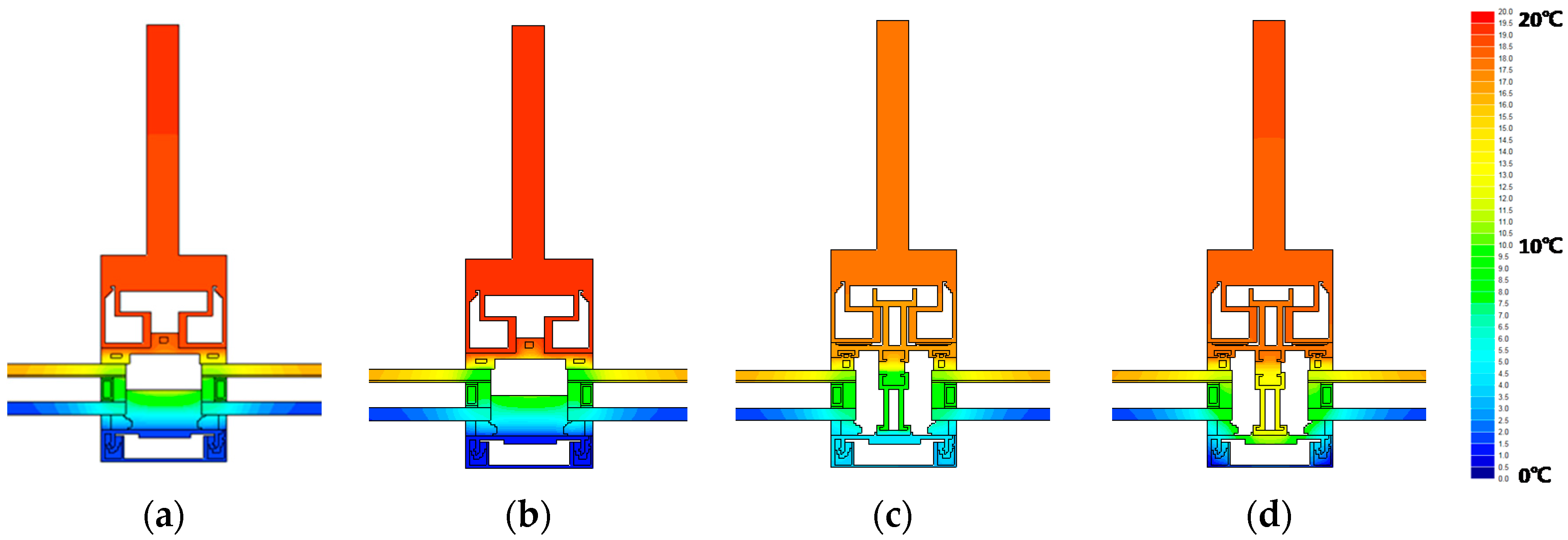
| Description | Specimen 1 | Specimen 2 | Specimen 3 |
|---|---|---|---|
| Glazing | 24 mm (6-12-6) double glazing with low-e coating, argon gas, and STS spacer | 42 mm (6-12-6-12-6) triple glazing with low-e coating, argon gas, and STS spacer | 42 mm (6-12-6-12-6) triple glazing with low-e coating, argon gas, and STS spacer |
| Frame type | Roll-formed | Roll-formed | Welded (T-shaped) |
| Filling | None | EPDM | EPDM |
| End cap | Steel cap | Polyamide cap | Polyamide cap |
| Mullion detail | 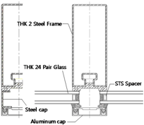 | 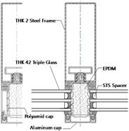 | 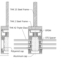 |
| Material | Thermal Conductivity (W/m·K) | Material | Thermal Conductivity (W/m·K) |
|---|---|---|---|
| Steel | 50 | Silicone Pure | 0.35 |
| Aluminum | 160 | Silicone Gasket a | 0.12 |
| Glass | 1 | PVC | 0.17 |
| Stainless Steel | 17 | EPDM a | 0.033 |
| Molecule Sieve | 0.1 | Polyurethane | 0.25 |
| Butyl Hot Melt | 0.24 | Polyamide | 0.25 |
| Evaluation Method | Specimen 1 | Specimen 2 | Specimen 3 | |||||
|---|---|---|---|---|---|---|---|---|
| UCW (W/m2·K) | Diff. (%) | UCW (W/m2·K) | Diff. (%) | UCW (W/m2·K) | Diff. (%) | |||
| Measurement (KS 2278) | 2.02 | - | 1.05 | - | 1.09 | - | ||
| Calculation (ISO 12631) | Single Assessment | Area-related | 2.013 | −0.3 | 1.090 | 3.8 | 1.094 | 0.4 |
| Length-related | 1.970 | −2.5 | 1.069 | 1.8 | 1.073 | −1.6 | ||
| Component assessment | 1.995 | −1.2 | 1.074 | 2.3 | 1.078 | −1.1 | ||
| Details of Rabbet Space | Shape of Head Profile | ||
|---|---|---|---|
| Case | Description | R Type | T Type |
| A | No filling material | 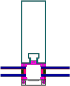 |  |
| B | Partially filled with EPDM | 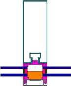 |  |
| C | Entirely filled with EPDM | 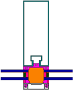 |  |
| D | Polyamide-bar thermal break | 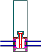 | 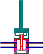 |
| E | Internal aluminum profile with polyurethane thermal break | 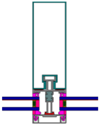 | 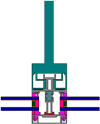 |
| Case | Case D | Case E | |||||
|---|---|---|---|---|---|---|---|
| Base | Step 1 | Step 2 | Base | Step 1 | Step 2 | ||
| T type | UCW (W/m2·K) | 1.972 | 1.862 | 1.779 | 2.421 | 2.294 | 1.957 |
| Red. Rate (%) | - | 5.6% | 9.8% | - | 5.2% | 19.2% | |
| R type | UCW (W/m2·K) | 1.920 | 1.822 | 1.735 | 2.32 | 2.216 | 1.918 |
| Red. Rate (%) | - | 5.1% | 9.6% | - | 4.5% | 17.3% | |
© 2016 by the authors; licensee MDPI, Basel, Switzerland. This article is an open access article distributed under the terms and conditions of the Creative Commons Attribution (CC-BY) license (http://creativecommons.org/licenses/by/4.0/).
Share and Cite
Oh, J.H.; Yoo, H.J.; Kim, S.S. Evaluation of Strategies to Improve the Thermal Performance of Steel Frames in Curtain Wall Systems. Energies 2016, 9, 1055. https://doi.org/10.3390/en9121055
Oh JH, Yoo HJ, Kim SS. Evaluation of Strategies to Improve the Thermal Performance of Steel Frames in Curtain Wall Systems. Energies. 2016; 9(12):1055. https://doi.org/10.3390/en9121055
Chicago/Turabian StyleOh, Ji Hyun, Hyun Jung Yoo, and Sun Sook Kim. 2016. "Evaluation of Strategies to Improve the Thermal Performance of Steel Frames in Curtain Wall Systems" Energies 9, no. 12: 1055. https://doi.org/10.3390/en9121055
APA StyleOh, J. H., Yoo, H. J., & Kim, S. S. (2016). Evaluation of Strategies to Improve the Thermal Performance of Steel Frames in Curtain Wall Systems. Energies, 9(12), 1055. https://doi.org/10.3390/en9121055