Abstract
Recently, second-life battery systems have received a growing interest as one of the most promising alternatives for decreasing the overall cost of the battery storage systems in stationary applications. The high-cost of batteries represents a prominent barrier for their use in traction and stationary applications. To make second-life batteries economically viable for stationary applications, an effective power-electronics converter should be selected as well. This converter should be supported by an energy management strategy (EMS), which is needed for controlling the power flow among the second-life battery modules based on their available capacity and performance. This article presents the design, analysis and implementation of a generic energy management strategy (GEMS). The proposed GEMS aims to control and distribute the load demand between battery storage systems under different load conditions and disturbances. This manuscript provides the experimental verification of the proposed management strategy. The results have demonstrated that the GEMS can robustly handle any level of performance inequality among the used-battery modules with the aim to integrate different levels (i.e., size, capacity, and chemistry type) of the second-life battery modules at the same time and in the same application.
1. Introduction
Recently, global electricity generation has swiftly grown in order to fulfill consumer demand. For instance, over the last four decades, the annual aggregate production of electricity increased from 6144 TWh to 23,391 TWh (terawatt hour), an average annual growth rate of 3.4% [1]. In 2013, the fossil fuel-powered plants (such as: oil, natural gas and coal/peat) contributed approximately 67.2% of the global electricity generation [1,2]. However, reliance on fossil fuels leads to increasing pollution of the environment and the deterioration of human health. Additionally, the depletion of fossil fuels is a concern and should be taken into account. Accordingly, the future electricity generation should reduce its reliance on fossil fuels by the growing use of clean and renewable energy generation sources.
The key problem with the renewable energy generation sources is that the output power fluctuates due to the nature of sources, including solar and/or wind. This fluctuation affects the grid stability and reliability. As a consequence, electrical energy storage (EES) has been recognized as one of the most promising approaches for increasing the grid efficiency, voltage stability and reliability, especially for optimizing power flows and supporting the renewable energy generation sources [2,3,4].
Furthermore, in the case of traction applications, vehicles can be powered by using battery storage systems instead of burning gasoline and diesel fuel in order to reduce associated emissions and the demand for oil. A serious weakness associated with rechargeable battery storage systems is the high cost of batteries, which represents a prominent barrier for their use in the automotive applications or as grid connected energy storage. As a rule, the cost of batteries can be decreased by lowering the material costs, enhancing the process efficiencies and increasing the production volume [5,6]. Another more effective solution is to re-use the retired battery systems, which have been utilized for powering the (hybrid) electric vehicles (i.e., plug-in hybrid electric vehicle (PHEV), hybrid electric vehicle (HEV) and battery electric vehicle (BEV)) for supporting the grid applications. Basically, there are two ways to use a vehicle’s battery system for grid applications [5,6]:
- (1)
- Vehicle-to-grid (V2G) application utilizes the battery for grid services, whereas the battery is still in the vehicle [7]; and
- (2)
- Second-life application utilizes the used-battery systems after retiring from vehicular services for stationary applications.
According to the latter option, second-life batteries are still expected to be capable of storing and delivering substantial energy. It is possible that they satisfy the requirements of stationary applications. Indeed, the total lifetime value of the battery will increase when the remaining capacity of batteries can be invested to meet the requirements of other energy-storage applications, which are less demanded as for EVs. Consequently, the price of the battery systems will be decreased allowing the widespread commercialization of both electric vehicles (EVs) and grid battery systems. Accordingly, there are two scenarios to use the second-life batteries in stationary applications as follows:
- ▪
- Classification the batteries into groups based on their characteristics (i.e., the remaining capacity, shape, and size) and select the most suitable application for each group; and
- ▪
- Reconfiguration of all types of batteries in the same application by using the proper power electronics converter.
Since non-standardized battery modules are used in different patterns of the EVs, it is challenging to find battery modules possessing the same capacity level. Therefore, this research work focused on the second scenario in order to integrate different levels of second-life battery modules into one economic battery storage system.
A limited number of studies of using the second-life battery systems for the stationary applications have been reported in the literature, and they can be divided into two main categories based on the interface converter [8,9,10,11,12,13]. Firstly, all the used-battery cells could be assembled in one package, and it is integrated with load or into the grid through a traditional two level converter [8,10,11,12]. According to [12], the authors presented a feasibility study of integrating a second-life battery pack with an off-grid photovoltaic (PV) vehicle charging system. This system has a PV array to charge a battery pack via a maximum power point tracking (MPPT) controller, and then the battery system charges a vehicle via a two level inverter. The second-life battery pack has 135 LiFePO4 based battery cells, which have been connected in series and parallel to provide a 13.9 kWh. Experimental results revealed that the used-battery system successfully achieved the desired function with a simple system structure and control methods. Another example, in [11], the authors developed a 20 kW PV panels (on the roof top of the test bed), five EVs, (Mitsubishi i-Miev G) and five second-life battery systems. This system aims to achieve a peak-load shifting by utilizing EVs, used battery systems and PV panels. This study revealed that the application of EVs and second-life EV batteries in supporting certain small-scale EMS is feasible. However, the overall reliability and service continuity of the whole system could be affected by the number of series connected battery cells. Accordingly, if only one cell fails, the entire module also fails because of the series connection of the batteries.
Secondly, the second-life battery cells could be assembled in isolated small modules, and they are integrated with load or into the grid through multi-level or multi-port converter [13,14]. According to [13], the authors proposed a modular boost-multilevel buck based converter topology and a module-based distributed control architecture. This study revealed that the performance of battery module can be evaluated based on weighting factors, which are dependent on initial SoC, voltage, impedance, and capacity, focusing on single phase applications. Therefore, this article focuses on three-phase grid integration. In addition, two levels of management strategies has been achieved as follows:
- (1)
- Cell level: using battery management system (BMS) for protecting battery cells against over-charge and over-discharge and balancing the cells that are connected in a series.
- (2)
- Module level: developing EMS with the aim to manage the energy flow and for distributing the load demand among the second-life battery modules.
In this article, a multi-port converter was supported by the energy management strategy (EMS) to control the power/energy flow among the used-battery modules. As a rule, the energy management concepts can be categorized into two main types: (1) rule-based; and (2) optimization-based energy management concepts [15,16,17,18]. These concepts are well suited for real-time applications. In case of optimization-based approaches, using these approaches lead to achieve the minimization of a cost function. However, a complex algorithm is needed to implement the optimization-based approach, while the rule-based control strategy provides a simple algorithm for controlling the energy flow among multiple DC sources.
The main objective of this paper is to develop an energy-management control strategy in order to control and distribute the power demand among three second-life modules under different load conditions and disturbances. The proposed generic energy management strategy (GEMS) has been developed for flexibly integrating different levels (i.e., size, capacity, and chemistry type) of the second-life battery modules into the grid through a multi-port converter. In this manuscript, a GEMS has been designed, implemented and analyzed based on the rule-based control strategy. In the following sections, the second-life battery module prototypes are explained in detail. Then, the experimental results are provided to realize the concept of the proposed GEMS.
2. Prototype Description of Second-Life Battery Modules
In the past five years, more than 700,000 total plug-in vehicles (plug-in hybrids and pure battery electrics) have been sold worldwide by the end of 2014 compared to about 400,000 at the end of 2013 [19]. Among the available battery technologies, it is clear that the current two main battery technologies used in EVs are nickel metal-hydride (NiMH) and lithium-ion (Li-ion). Due to the potential of obtaining higher specific energy and energy density, the adoption of Li-ion batteries is expected to grow fast in EVs, particularly in PHEVs and BEVs. Therefore, this research study focused on Li-ion batteries.
One of the safest lithium ion battery chemistries is the lithium iron phosphate battery (LiFePO4), also called LFP battery, which is attractive solution compared to other chemistries due to its low cost, low toxicity, flat charge/discharge voltage and relatively good cycle life [20]. Thus, in this manuscript, the LiFePO4 batteries have been selected in order to investigate the potential of using this technology for second-life batteries for stationary applications.
According to US Council for Automotive Research (USCAR), the second-life batteries are the batteries that are retired from the vehicle when they can no longer provide 80% of the rated capacity (needed for vehicle range) [21,22,23]. Accordingly, one of the main tasks in this research project was how to provide the used-batteries (remaining capacity ≤80% of rated capacity), which can be used to evaluate the performance of the used-batteries and to build three second-life modules. Therefore, 27 new cells (7 Ah high power cells, Energy Innovation Group Ltd. (EIG), Korean-Based ISO/TS16949 Certified Manufacturer, Cheonan-si, Korea) have been aged using different charge/discharge profiles in the laboratory. The EIG battery is a pouch cell with LiFePO4-based cathode and carbon-based anode, where the electrical parameters of the EIG cells are provided in Table 1. This technology was designed for using in HEVs according to the manufacturer datasheet.

Table 1.
Electrical parameters of the batteries that used in this research [24,25]. EIG: Energy Innovation Group Ltd.
All tests (i.e., lifecycle, and characterization) have been carried out in two laboratories (Battery Innovation Center laboratory at Vrije Universiteit Brussel and energy laboratory at Vito in Mol, Belgium) by using PEC battery tester, which is developed by PEC Company (Leuven, Belgium), as shown in Figure 1.
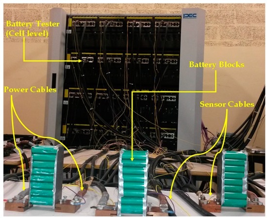
Figure 1.
PEC battery tester for testing and evaluating industrial battery cells and modules.
Based on factual application, the used-battery pack, which was used in PHEV and retired after more than five years of usage, has been included in this evaluation. As shown in Figure 2, this pack has been dismantled into blocks and randomly 35 blocks have been taken for evaluation, and then they refurbished for the second use in stationary applications. Table 1 shows the electrical parameter of the used-battery cells (LiFePO4-18650 cylindrical).
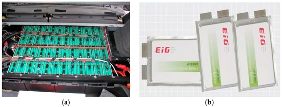
Figure 2.
Second-life battery cells/blocks: (a) battery blocks (32.4 Ah) that used in plug-in hybrid electric vehicle (PHEV) for more than five years; and (b) battery cells EIG (7 Ah).
Finally, the battery cells and blocks have been tested and sorted with the aim to refurbish these batteries, and then integrate them into the grid.
To evaluate the performance of the second-life battery modules in stationary applications, an experimental setup of three second-life modules, which have been integrated into the grid by using a multi-port converter and a three-phase inverter. A setup is also developed and used to verify the viability of sharing the load demand among the second-life modules by using the proposed GEMS, as will be presented in the following section. Figure 3 shows the block diagram of the overall experimental system that used in the Vito’s laboratory.
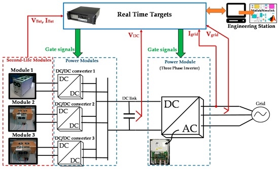
Figure 3.
The block diagram of the overall system for integrating the three second-life modules into the grid.
In the framework of this research, a distributed power system (DPS) has been used to implement three-phase grid-connection up to 11 kW with a constant voltage of the DC link at 700 V and three independent bidirectional DC/DC converters. The nominal current of each DC/DC converter in DSP is 32 A. As can be seen in Figure 3, Real-Time Target (RTT) is used to run both slow and fast varying control loops. Moreover, the RTT can be programmed and operated through Matlab/Simulink (Figure 3). It communicates with power modules (i.e., DC/DC converter, and three-phase inverter) and measurement sensors (i.e., current, and voltage sensors) via the Ethernet communication protocol. Thus, all control algorithms can be realized as block diagrams in Matlab/Simulink, following which, the Real-Time Workshop automatic code generator translates these block diagrams to C-code, compiled and executed on the Real-Time Target.
Furthermore, three second-life battery modules have been built and integrated into the grid through the DPS, as shown in Figure 3. The second-life battery cells and blocks have been refurbished in order to build three second-life battery modules. The battery cells and blocks have been assembled in series to build one battery module (Module 1) by using 15 EIG (7 Ah) battery cells, and an additional two battery modules (Modules 2 and 3) based on 30 battery blocks (15 blocks per module).
Table 2 shows the discharge capacity retention (DCR) of the used-battery cells/blocks, which have been used to build three second-life battery modules. The selection of the used-battery cells/blocks, which have been assembled in the same battery module, relied on the feasible equality in the DCR that was measured at 1It. According to the International Standard IEC61434 [26], It (A) is the reference test current, which is expressed as where Cn can be define as the rated capacity, which is measured during a specific time n (h), of the battery cell.
Table 2.
The discharge capacity retention (DCR) of the used-battery cells and blocks, which have been used to build three second-life battery modules.
Practically, the used-battery cells/blocks have been selected at the lowest possible difference in the DCR (9% in module 1 and 5% in modules 2 and 3) as listed in Table 2.
The verification of the proposed EMS that was designed for the second-life battery system will be discussed in the following section. Two types of used-battery modules have been designed and implemented. In the first type, the battery cells have been assembled in one module (Module 1), which can be used to provide approximately 6 Ah and 0.7 kW (rated power). The second type consists of two modules (Modules 2 and 3) that are utilized to produce 3 kW (rated power) and relatively high capacity (~26 Ah) compared to Module 1. The electrical parameters of the second-life modules used in this study are reported in Table 3. In general, the efficiency and the Ah discharge of the used-battery cells/blocks increases with decreasing the charge/discharge current rate (≤2It). Consequently, the rated power of these battery modules is computed by multiplying the voltage (almost flat ~50 V) and the rated current (2It).
Table 3.
Electrical parameters of the used-battery modules.
To connect the second-life battery modules to the DSP, these battery modules consist of 15 battery cells/blocks, which have been connected in series, to produce a sufficient output voltage (~50 V). As a rule, connecting battery cells in series opens up the possibility of cell imbalance between identical battery cells in the same string. In case of the second-life battery cells, additional imbalance occurs due to the difference in the DCR (Table 2). Hence, the importance of using a BMS strongly appears with the aim to overcome the imbalance in the voltage and capacity of the used-battery cells. Among the commercial BMS types (i.e., passive or active), the passive BMS is adequate to build a low-cost and simple battery balancing system.
Commercially, most BMSs (passive) available in the market provide almost the same functions, such as:
- ▪
- measuring parameters (i.e., voltage, current, temperature, and internal resistance);
- ▪
- safety protection to protect the battery cell against over-temperature, over-charging, over-discharging and charge/discharge current limit; and
- ▪
- Communication unit by using isolated RS-485 and/or CAN-bus.
However, the balancing current and the price of the BMS were the main criteria that were identified in order to select one of them.
Regarding the balancing current, the required balancing time mainly depends on the amplitude of the balancing current, and it can be computed by: imbalance in capacity (Ah)/the balancing current (A). As can be seen in Figure 4, the required balancing time has been computed to eliminate the imbalance in capacity (9% for battery cells and 5% for battery blocks) of battery cells/blocks at different balancing current levels (100 mA, 150 mA, 450 mA, 1000 mA, and 1300 mA). The results of this calculation revealed that the balancing time can be clearly decreased by increasing the balancing current. Therefore, passive BMS was selected due to its lower price (€295) and relative higher balancing current (1300 mA) compared to other BMS modules.
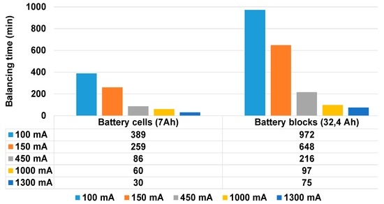
Figure 4.
The required balancing time to eliminate the imbalance in capacity (9% for battery cells and 5% for battery blocks) at different balancing current levels (100 mA, 150 mA, 450 mA, 1000 mA and 1300 mA).
As shown in Figure 5 and Figure 6, the BMS utilizes a passive BMS to equalize the voltage of the battery cell by using 15 ohmic resistors (switched shunt resistors BMS). The BMS has the ability to protect and balance the battery cells by monitoring battery cell voltage, current, and temperature. The BMS measures the battery module current via a low-side precision shunt ohmic resistor (±0.25% accuracy). The shunt ohmic resistor consists of a four-wire Kelvin connection, which is used to measure the voltage drop across the resistor. In addition, a short shielded cable (50 cm) is used to connect the shunt ohmic resistor and BMS (Figure 6). To filter out the current spikes or noise, the BMS has a high precision analog-to-digital converter (ADC). The temperature of the battery module is monitored by eight temperature sensors.
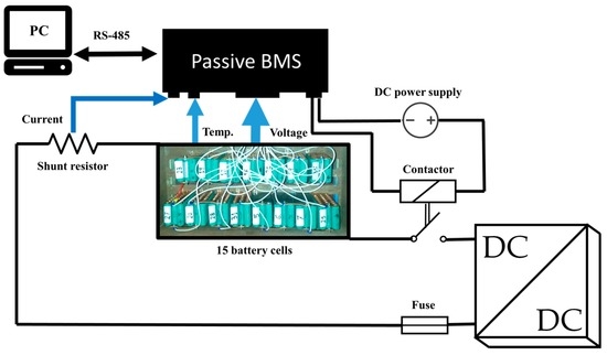
Figure 5.
The block diagram of the experimental setup of the second-life module by using battery management system (BMS).
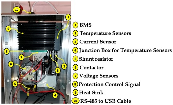
Figure 6.
Prototype of BMS connection by using BMS.
The passive BMS dissipates the balanced energy and causes an undesirable BMS temperature rise. Thus, extra power consumption is needed for cooling. As shown in Figure 6, a heat sink and cooling fans have been used to maintain the BMS’s temperature within the desirable level (≤40 °C).
To clearly show the importance of using a cooling system with the passive BMS, Figure 7 illustrates the experimental results of balancing 15 battery cells with and without cooling system. In Zones A, B, and C (without cooling), it is clear that the BMS could not complete the balancing (Figure 7) in order to protect the circuit from over-heating (>40 °C). The BMS with cooling system (Zone D), the BMS’s temperature becomes more stable and heats up slowly, and thus can achieve the balancing among the battery cells, as shown in Figure 7.
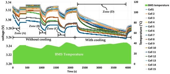
Figure 7.
Experimental results of the BMS’s performance with and without air cooling system.
Finally, Figure 8 depicts the prototypes of three second-life modules that were used in this research work.
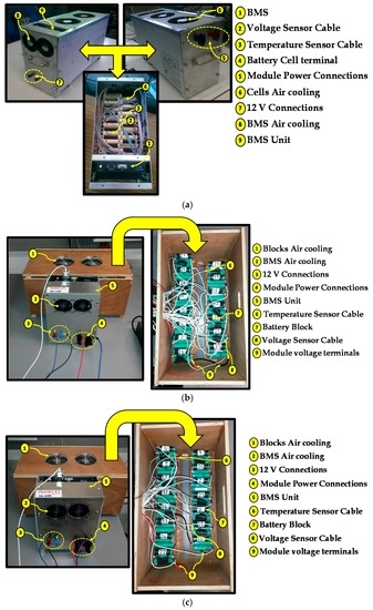
Figure 8.
Prototype of three second-life modules: (a) module 1 (6 Ah); (b) module 2 (26 Ah); and (c) module 3 (26 Ah).
3. Design of Generic Energy Management Strategy
As mentioned previously in Section 2, the EMS and all control algorithms have been implemented as block diagrams on Matlab/Simulink. The control algorithms for generating the gate pulses (10 kHz switching frequency) of the DC/DC converters and the DC/AC converter have been already designed on Matlab/Simulink. Based on this available design (Figure 9), each DC/DC converter is controlled by using closed-loop proportional-integer (PI) controllers (current control). To maintain the DC link at constant voltage (i.e., 700 V), the ratio of battery module voltage (VB) and the voltage of the DC link (VDC) is added to the output of the PI-controller to produce the desired duty cycle. This duty cycle is converted to gate signals by using drive control toolbox on Matlab/Simulink, as shown in Figure 9.
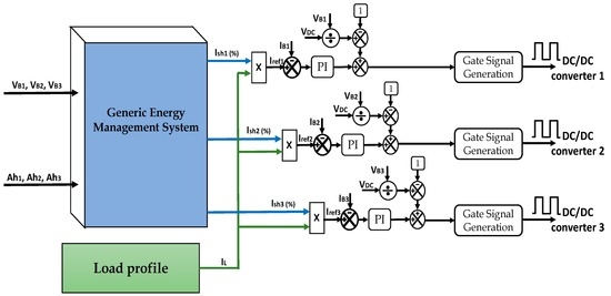
Figure 9.
The schematic diagram of the generic energy management strategy (GEMS) with closed-loop current control strategy.
Therefore, this article focuses on developing an efficient GEMS of multiple energy sources, particularly for the second-life battery modules. As can be seen in Figure 9, the inputs for the GEMS are the voltage and Ah of each battery module. Based on the performance of the used-battery modules, the GEMS provides the sharing percentage of the load demand among the battery modules. Accordingly, the charge/discharge current value of each module is adjusted based on the GEMS output, which is used as a reference signal to realize the closed-loop current control strategy. The self-consumption of PV profile (see Appendix A) was also implemented as a block on Matlab/Simulink with the aim to verify the proposed GEMS, as shown in Figure 9.
The main function of the proposed GEMS is to distribute the load current among the used-modules based on their performance. The voltage (VB) and capacity (Ah) of the battery modules have been selected to evaluate the performance of each module. In general, the Ah of each battery module is basically computed by using a Coulomb counting technique [27,28], which can be expressed as:
where SOCint is the initial value of SoC, iB is the battery current (positive during charge and negative during discharge), and Cm is the measured capacity at 1It, where i is the number of battery modules. The initial value has been determined by using a predefined SoC versus open circuit voltage (OCV) lookup table. As a consequence, the initial capacity (Ahint) of each battery module can be computed based on Equations (2) and (3):
In general, the instantaneous capacity of any battery module can be calculated by Equation (4):
By substituting Equation (1) into Equation (4), we can instantaneously calculate the capacity of battery module:
Based on the voltage and the current of each battery module, the output power of battery module can be computed as follows:
To simply evaluate the performance of each battery module, these factors (voltage and capacity) are combined into one control factor, which is called the voltage-capacity-ratio (VCR), and it can be computed by Equation (9):
However, it has raised an important question about the relevance of using a VCR (V/Ah). In case of renewable energy applications (i.e., self-consumption of PV profile), the battery modules are used to manage the fluctuation of the renewable source (see Figure A1 in Appendix A). The required current from battery modules may suddenly change from low to high value in few seconds for specific period based on the nature of renewable sources. The fast dynamic load profile will reflect an oscillation in the voltage of battery modules. This oscillation in battery module’s voltage can be amplified by multiplying the voltage by capacity (V·Ah), which will negatively affect the performance of the EMS. In contrast, the VCR factor has the ability to reduce the oscillation in voltage due to the voltage is divided by the Ah. Figure 10 shows the simulation results of the battery module (6 Ah, 50 V) with the aim to compute the oscillation in the VCR and V·Ah factor due to using fast dynamic current profile (from 5 A to 30 A in 5 s). It is clear that the oscillation in VCR is lower (~0.2) than in V·Ah factor (~20). This is the reason why the VCR factor was selected in this research work.
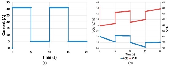
Figure 10.
Simulation results of 6 Ah battery module (15 cells in series) at 50% SoC: (a) battery current; and (b) voltage-capacity-ratio (VCR) and energy.
In the proposed GEMS, the VCR of each battery module is calculated in order to identify their performance during the operating process. In Figure 11, the inputs of the GEMS are the voltage and Ah of the three used-battery modules. Based on the voltage and Ah, the VCR is determined, and then the lowest VCR is computed by using Equation (10):
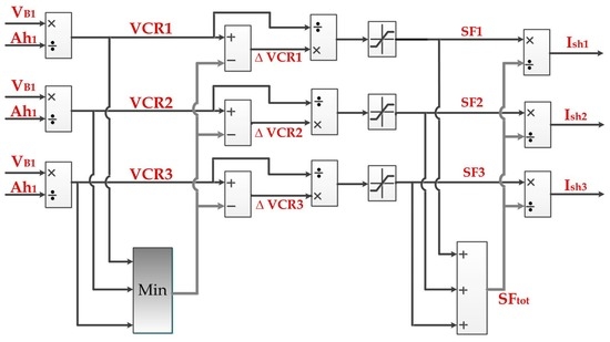
Figure 11.
The GEMS. SF: sharing factor.
It is important to point out that the GEMS is designed to share the load demand among the high performance battery modules, which have higher VCR. The battery module with the lowest VCR will not participate in feeding the load, and the lowest VCR is used as a reference level to compare among the other modules’ performance. Therefore, ΔVCR indicates the performance difference of the used-battery modules (see Equation (11)). Afterwards, the ΔVCR is converted to per-unit value and limited between 0 and 1 with the aim to compute the sharing factor (SF) (see Equation (12)). Consequently, the sharing current (Ish) for each battery module can be determined based on Equations (13) and (14):
where n is the total number of battery modules, and I = 1, 2, …, n.
As a result, the desired battery module current can be computed based on multiplying the sharing percentage (Ish) by load current (IL) as follows:
According to Equations (5), (8) and (15), one can observe that the power flow from battery side to AC side mainly depends on the VCR of each battery module, which in turn reflects the performance of each battery module.
For instance, Figure 12 shows how the load demand is shared between battery modules 1 and 2 based on the level of the VCR of each module. It is clear that the load current is equally shared (50%) between battery modules 1 and 2. In addition, battery module 3 is not participating in feeding because it has the lowest VCR level. The experimental results and the validation of the GEMS concept will be presented in the next section.
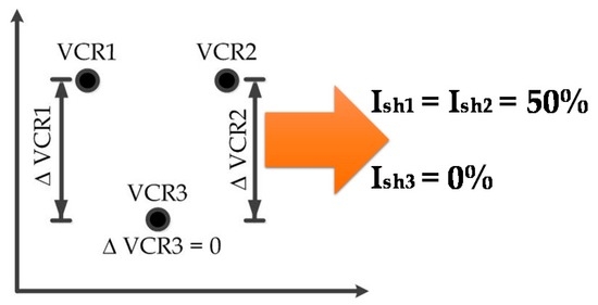
Figure 12.
An example of the GEMS’s output based on the level of the VCR of each battery module.
In the case of using different sizes of the second-life battery modules (i.e., 6 Ah, 26 Ah, and 26 Ah) in the same application, the Ah level of the used-battery modules should be fixed at the same level, and thus the system can simply assess their performance. This is the reason why the capacity of the first battery module (Ah1) was multiplied by a calibration factor (26/6 = 4.33).
4. Experimental Results
The experimental results aim to validate the ability of the GEMS for controlling the energy flow of three second-life modules under different load conditions and disturbances, as will be presented in the following section. The voltage and current of each battery module have been measured at two levels: (1) at the cell level by using the BMS module; and (2) at the module level by using the DPS measurement units. Before using the DPS, the measured voltage of each battery module has been calibrated. As shown in Figure 13, the measured voltage of three battery modules by using the BMS and the DPS system is almost the same.
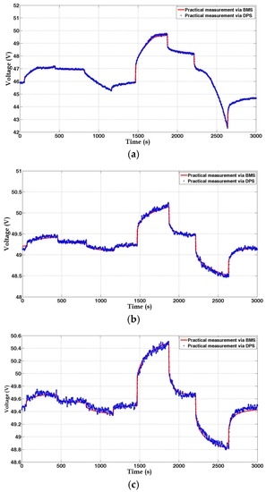
Figure 13.
The voltage of three battery modules during charge and discharge: (a) module 1; (b) module 2; and (c) module 3.
4.1. Load Profile without Disturbance
In this section, the experimental test has been performed by using the self-consumption of PV profile. This load profile consists of four different load conditions, including base load, medium load, cooking hob, and base load plus offset. The initial SoC of the used-battery modules has been adjusted to be 95%, 80%, and 52% SoC for module 3, module 2, and module 1, respectively, as shown in Figure 14. In addition, Figure 15 shows the voltage of each battery module. In Figure 16, battery modules 3 and 1 have the highest and lowest initial VCR, respectively. It is clear that the SoC difference among the used-battery modules has been decreased from 43% to less than 5% thanks to the proposed EMS (Figure 17). Accordingly, the required discharging current has been shared between modules 2 and 3 (Figure 18), and also the magnitude of the shared current mainly depends on the VCR3 and VCR2 during the discharging process, as shown in Figure 16 and Figure 18. Thus, the experimental results revealed that the GEMS managed to control the energy flow among the used-battery modules by evaluating the status of these battery modules based on their VCR (Figure 14, Figure 15, Figure 16, Figure 17 and Figure 18).
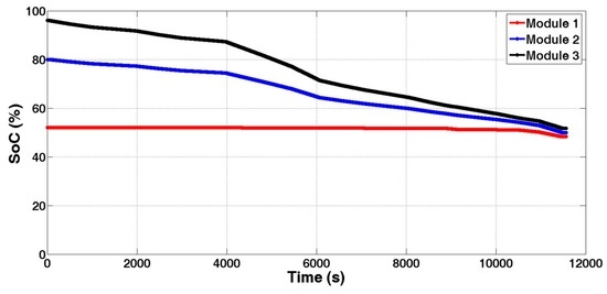
Figure 14.
The SoC of the second-life battery module.
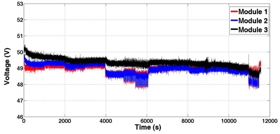
Figure 15.
The measured voltage of the used-battery modules.
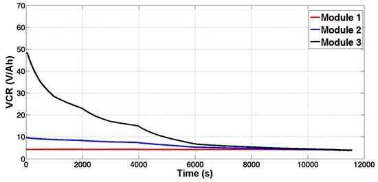
Figure 16.
The VCR of the used-battery modules.
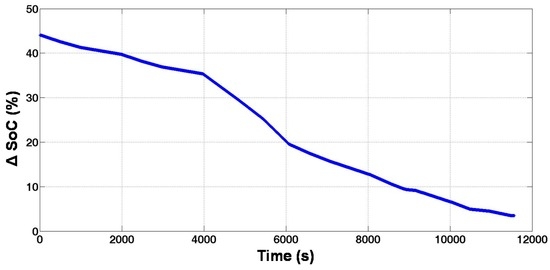
Figure 17.
The SoC difference among the used-battery modules.
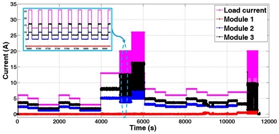
Figure 18.
Discharge current load based on self-consumption of photovoltaic (PV) profile and the sharing current of each battery module.
To achieve a desired output current from each battery module, a PI controller has been utilized to compensate the error between the reference and measured current value. One can see from Figure 19 that the measured current is very close to the reference current.
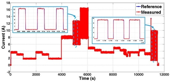
Figure 19.
An example of the reference and the measured current of the closed-loop proportional-integer (PI) controller (module 3).
The passive BMS has been used for monitoring, protecting and balancing the battery cells/blocks. To verify that the BMS was successful in eliminating the imbalance in voltage during the operation, Figure 20 illustrates the voltage levels of all battery cells/blocks, which have been connected in series, in modules 1–3. The BMS has been adjusted to limit the imbalance in voltage to be less than 20 mV. Indeed, the BMS managed to restrict the imbalance in voltage (≤20 mV), even with the fast current rate in some periods during the discharge operation, as shown in Figure 20.
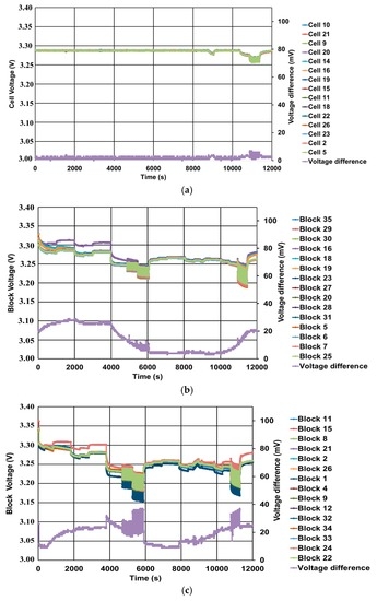
Figure 20.
The voltage levels of all battery cells/blocks: (a) module 1; (b) module 2; and (c) module 3.
4.2. Load Profile with Disturbance
Since the battery life significantly affects the reliability of the battery-storage system for providing a continuous feed, it is necessary to verify the ability of the proposed GEMS to face any potential malfunction in the used-battery modules during the operation. Therefore, to investigate the performance of the GEMS against different operating conditions, the initial SoC of the used-battery modules has been changed to what was used in previous section (97%, 73%, and 86% SoC for module 3, module 2, and module 1, respectively), as shown in Figure 21. Moreover, this section will focus on the first part of the self-consumption of PV profile, which is called base load, and the battery modules have been subjected to three disturbance cases as shown in Figure 22. The disturbance cases can be summarized as follows:
- ▪
- Case 1: malfunction in battery module 1 with inequality in the VCR of the other battery modules;
- ▪
- Case 2: malfunction in battery module 3 with inequality in the VCR of the other battery modules;
- ▪
- Case 3: malfunction in battery module 3 with equality in VCR of the other battery modules.
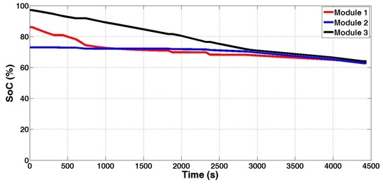
Figure 21.
The SoC of the second-life battery module.
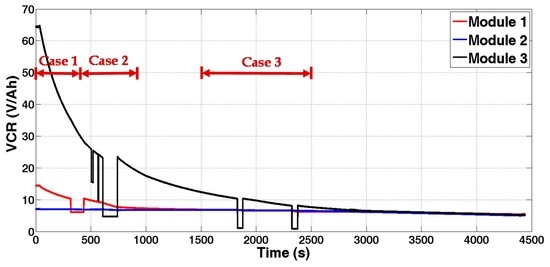
Figure 22.
The VCR of the used-battery modules with three disturbance cases.
Before discussing the disturbance cases, it is clear that the proposed GEMS was able to share the load demand among the used-battery modules based on their performance. Furthermore, the GEMS is robust enough to handle any level of performance inequality among the used-battery modules in order to integrate different levels of the second-life battery modules in the same application. Thus, the GEMS supports the low performance battery modules which are “helped” by the high performance battery modules (Figure 21 and Figure 23).
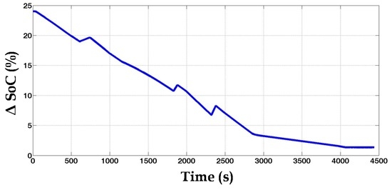
Figure 23.
The SoC difference among the used-battery modules.
4.2.1. Case 1
In this case, before applying the disturbance, the load demand was shared between battery modules 1 and 3 since the VCR2 was the lowest value compared to other values. Suddenly, the VCR1 is manually decreased to be lower than the VCR3. Thus, the GEMS directly re-distributed the load demand between battery modules 2 and 3, as shown in Figure 24.
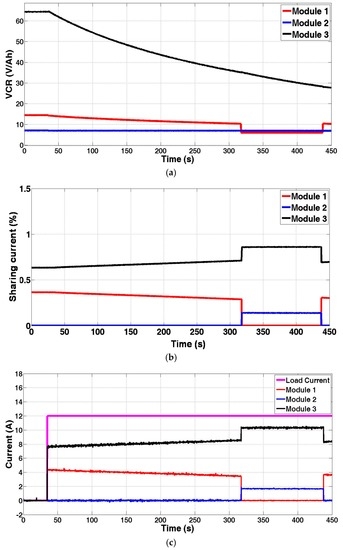
Figure 24.
The performance of the proposed GEMS (Case 1): (a) VCR; (b) sharing current; and (c) current.
4.2.2. Case 2
To clearly show the ability of the GEMS to distribute the current based on the VCR value, the VCR3 has been decreased to three different levels (zones A, B, and C), as shown in Figure 25. In zones A and B, the current of module 1 increases with decreasing the VCR3, and thus these battery modules almost provided the same current when their VCR reached equal levels with subtle nuances as in zone B. In zone C, due to the fact that the VCR1 and VCR2 is higher than VCR3, the GEMS re-distribute the load demand between battery modules 1 and 2 (Figure 25).
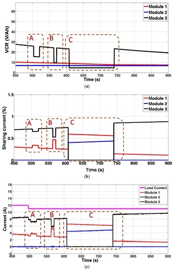
Figure 25.
The performance of the proposed GEMS (Case 2): (a) VCR; (b) sharing current; and (c) current.
4.2.3. Case 3
In this case, the VCR1 and VCR2 reached almost the same level, which is lower than the VCR3. Therefore, the battery module 3 could afford the highest current value compared to the other battery modules. Consequently, the GEMS equally re-distributed the load demand between the battery modules 1 and 2, when the VCR3 sharply declined to a level lower than VCR1 and VCR2, as shown in Figure 26.
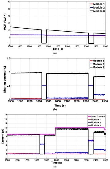
Figure 26.
The performance of the proposed GEMS (Case 3): (a) VCR; (b) sharing current; and (c) current.
5. Conclusions
In this paper, three second-life battery modules have been integrated into the grid through a multi-port DC/DC converter and DC/AC converter. To build the used-battery modules, the second-life battery cells/blocks have been assembled to form modules (6 Ah, 26 Ah, and 26 Ah). The commercial BMS has been used for monitoring, protecting, and balancing the battery cells that are connected in series. Indeed, the experimental results revealed that the BMS managed to restrict the imbalance in voltage (≤20 mV).
Furthermore, this paper mainly proposes an innovative GEMS, which can be used for managing the energy flow and for distributing the load demand among the second-life battery modules. Obviously, it is evident that the GEMS successfully controlled the energy flow among the used-battery modules by evaluating the status of these battery modules. The GEMS actively handles any level of performance inequality (from 45% difference in SoC between modules to approximately difference ≤5%) among the used-battery modules with the aim to integrate different size, chemistry and/or capacity levels of the second-life battery modules in the same application and at the same time. In addition, the GEMS has the ability of facing any potential malfunction in the used-battery modules during the operation in order to provide a reliable battery system.
Finally, it should be noted that the selection of the appropriate power electronic converter and EMS are very important for efficiently reusing the second-life battery modules in the stationary applications.
Acknowledgments
We acknowledge Flanders Make for supporting our team. We also acknowledge Vito for supporting this Project.
Author Contributions
Mohamed Abdel-Monem designed, performed and analyzed the experiments, and wrote the paper; Omar Hegazy contributed in designing and analyzing the experiments and editing the manuscript; Noshin Omar contributed in designing the used battery modules and editing the manuscript; Khiem Trad and Sven De Breucker contributed in preparing the test bench and providing fruitful discussions; Joeri Van Mierlo and Peter Van Den Bossche are the promoters who lead this research project and edit the manuscript.
Conflicts of Interest
The authors declare no conflict of interest.
Nomenclature
| Ahint | Initial capacity (Ah) |
| Cn | Rated capacity |
| Cm | Measured capacity |
| Instantaneous battery current of the ith module | |
| Ish | Sharing current |
| IL | Load current |
| OCV | Open circuit voltage |
| Pi | Battery power of the ith module |
| SoC | State-of-charge (%) |
| SoCint | Initial value of SoC |
| VB | Battery module voltage |
| VDC | Voltage of DC Link |
| VCRi(t) | Instantaneous voltage-capacity ratio of the ith module |
| SF | Sharing factor |
Appendix A. Dynamic Load Profile
Figure A1 shows a representative cycle for a battery system that is used for self-consumption of PV generated energy in a household dwelling. The cycle is based on measurements in seven houses with 1 s resolution. They all showed similar patterns as follows:
- ▪
- Refrigerators and freezers (low power);
- ▪
- Cooking hobs, microwaves (pulse width modulation behavior);
- ▪
- Constant power consumption periods due to, e.g., vacuum cleaning and washing machines; and
- ▪
- PV generation can be spiky due to clouds.
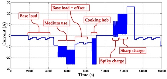
Figure A1.
Self-consumption of PV profile.
Appendix B. Control of the DC/DC Converter
The duty cycle of the DC/DC converters divided in two terms:
- (1)
- The first term is the feed-back (Dfb) controlled by the current controller using a PI-controller.
- (2)
- The second term is the feed-forward (Dff). In this case, the duty cycle is computed by measuring the battery voltage VB and the DC-link voltage VDC as follows:
Appendix C. Control of the DC/DC Converter
DPS (Figure C1) consists of:
- (1)
- 11 kW three-phase grid-connection keeps dc-link at 700 V; and
- (2)
- Three independent DC/DC converters: bidirectional power exchange with grid, Nominal current 32 A and peak current 48 A per converter.
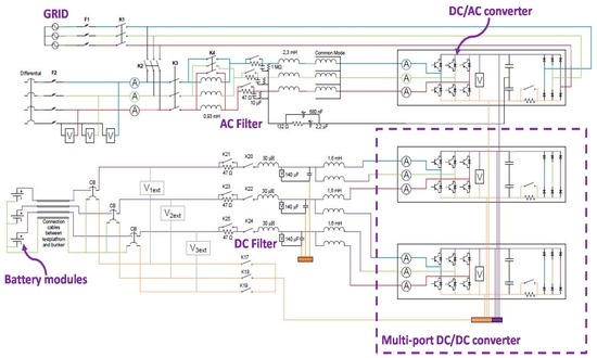
Figure C1.
Structure of distributed power system (DPS).
References
- Key Electricity Trends Excerpt from: Electricity Information; International Energy Agency (IEA): Paris, France, 2015.
- Luo, X.; Wang, J.; Dooner, M.; Clarke, J. Overview of current development in electrical energy storage technologies and the application potential in power system operation. Appl. Energy 2015, 137, 511–536. [Google Scholar] [CrossRef]
- Lott, M.C.; Kim, S.I. Technology Roadmap: Energy Storage; International Energy Agency (IEA): Paris, France, 2014. [Google Scholar]
- Landry, M.; Gagnon, Y. Energy storage: Technology applications and policy options. Energy Procedia 2015, 79, 315–320. [Google Scholar] [CrossRef]
- Neubauer, J.S.; Pesaran, A.; Williams, B.; Ferry, M.; Eyer, J. A techno-economic analysis of PEV battery second use: Repurposed-battery selling price and commercial and industrial end-user value. In Proceedings of the SAE 2012 World Congress & Exhibition, Detroit, MI, USA, 24–26 April 2012.
- Viswanathan, V.V.; Kintner-Meyer, M. Second use of transportation batteries: Maximizing the value of batteries for transportation and grid services. IEEE Trans. Veh. Technol. 2011, 60, 2963–2970. [Google Scholar] [CrossRef]
- Mültin, M.; Allerding, F.; Schmeck, H. Integration of Electric Vehicles in Smart Homes—An ICT-Based Solution for V2G Scenarios. In Proceedings of the 2012 IEEE PES Innovative Smart Grid Technologies (ISGT), Washington, DC, USA, 16–18 January 2012.
- Tong, S.; Klein, M. Second life battery pack as stationary energy storage for smart grid. In Proceedings of the SAE 2014 World Congress & Exhibition, Detroit, MI, USA, 8–10 April 2014.
- Gladwin, D.T.; Gould, C.R.; Stone, D.A.; Foster, M.P. Viability of “Second-Life” Use of Electric and Hybridelectric Vehicle Battery Packs. In Proceedings of the IECON 2013—39th Annual Conference of the IEEE Industrial Electronics Society, Vienna, Austria, 10–13 November 2013; pp. 1922–1927.
- Lacey, G.; Putrus, G.; Salim, A. The Use of second Life Electric Vehicle Batteries for Grid Support. In Proceedings of the 2013 IEEE EUROCON, Zagreb, Croatia, 1–4 July 2013; pp. 1255–1261.
- Aziz, M.; Oda, T.; Mitani, T.; Watanabe, Y.; Kashiwagi, T. Utilization of electric vehicles and their used batteries for peak-load shifting. Energies 2015, 8, 3720–3738. [Google Scholar] [CrossRef]
- Tong, S.J.; Same, A.; Kootstra, M.A.; Park, J.W. Off-grid photovoltaic vehicle charge using second life lithium batteries: An experimental and numerical investigation. Appl. Energy 2013, 104, 740–750. [Google Scholar] [CrossRef]
- Mukherjee, N.; Strickland, D. Control of second-life hybrid battery energy storage system based on modular boost-multilevel buck converter. IEEE Trans. Ind. Electron. 2015, 62, 1034–1046. [Google Scholar] [CrossRef]
- Soong, T.; Lehn, P.W. Evaluation of emerging modular multilevel converters for BESS applications. IEEE Trans. Power Deliv. 2014, 29, 2086–2094. [Google Scholar] [CrossRef]
- Bocklisch, T. Hybrid energy storage systems for renewable energy applications. Energy Procedia 2015, 73, 103–111. [Google Scholar] [CrossRef]
- Salam, B.; Kader, K.S.M.; Universiti, I.; Hussein, T. A Review of Energy Management System in Battery Electric Vehicle with Hybrid Electrical Energy Source. In Proceedings of the FEIIC—International Conference on Engineering Education and Research, Madinah, Saudi Arabia, 19–21 December 2015.
- Arabali, A.; Ghofrani, M.; Etezadi-Amoli, M.; Fadali, M.S.; Baghzouz, Y. Genetic-algorithm-based optimization approach for energy management. IEEE Trans. Power Deliv. 2013, 28, 162–170. [Google Scholar] [CrossRef]
- Hegazy, O.; Van Mierlo, J.; Lataire, P. Control and analysis of an integrated bidirectional DC/AC and DC/DC converters for plug-in hybrid electric vehicle applications. J. Power Electron. 2011, 11, 408–417. [Google Scholar] [CrossRef]
- Climate Progress. Electric Car Batteries Just Hit a Key Price Point. 2015. Available online: http://thinkprogress.org/climate/2015/04/13/3646004/electric-car-batteries-price/ (accessed on 2 June 2016).
- Tan, Q.; Lv, C.; Xu, Y.; Yang, J. Mesoporous composite of LiFePO4 and carbon microspheres as positive-electrode materials for lithium-ion batteries. Particuology 2014, 17, 106–113. [Google Scholar] [CrossRef]
- Cready, E.; Lippert, J.; Pihl, J.; Weinstock, I.; Symons, P.; Jungst, R.G. Final Report Technical and Economic Feasibility of Applying Used EV Batteries in Stationary Applications: A Study for the DOE Energy Storage Systems Program; No. SAND2002-4084; Sandia National Laboratories: Albuquerque, NM, USA; Livermore, CA, USA, 2003.
- Wood, E.; Alexander, M.; Bradley, T.H. Investigation of battery end-of-life conditions for plug-in hybrid electric vehicles. J. Power Sources 2011, 196, 5147–5154. [Google Scholar] [CrossRef]
- Omar, N.; Daowd, M.; Hegazy, O.; Geukens, B.; Coosemans, J.M.; Van den Bossche, P.; Van Mierio, J. Assessment of second life of lithium iron phosphate based batteries. Int. Rev. Electr. Eng. 2012, 7, 3–12. [Google Scholar]
- Batteryspace. LiFePO4 18650 Cylindrical Battery Specification. 2006. Available online: https://www.batteryspace.com/prod-specs/LFP18650.pdf (accessed on 10 June 2016).
- Energy Innovation Group Ltd. (EIG). Overview ePLB. Available online: http://www.eigbattery.com/_eng/designer/skin/03/01.asp (accessed on 2 August 2015).
- Omar, N.; Daowd, M.; Hegaz, O.; Mulder, G.; Timmermans, J.M.; Coosemans, T.; Van den Bossche, P.; Van Mierlo, J. Standardization work for BEV and HEV applications: Critical appraisal of recent traction battery documents. Energies 2012, 5, 138–156. [Google Scholar] [CrossRef]
- Kim, J.; Shin, J.; Chun, C.; Cho, B.H. Stable configuration of a Li-ion series battery pack based on a screening process for improved voltage/SOC balancing. IEEE Trans. Power Electron. 2012, 27, 411–424. [Google Scholar] [CrossRef]
- Omar, N.; Daowd, M.; van den Bossche, P.; Hegazy, O.; Smekens, J.; Coosemans, T.; Van Mierlo, J. Rechargeable energy storage systems for plug-in hybrid electric vehicles-assessment of electrical characteristics. Energies 2012, 5, 2952–2988. [Google Scholar] [CrossRef]
© 2016 by the authors; licensee MDPI, Basel, Switzerland. This article is an open access article distributed under the terms and conditions of the Creative Commons Attribution (CC-BY) license (http://creativecommons.org/licenses/by/4.0/).