Abstract
In recent years, the need for autonomous underwater vehicles (AUVs) for offshore infrastructure maintenance and oceanographic surveillance has been prominently increasing. Continuous monitoring and surveillance are the essential tasks the AUVs are designed to perform. However, the long endurance of the AUV is a challenging task due to the limited size and capacity of the onboard battery. The conventional way of recharging using battery swapping or a wet mate connector limits the autonomy of the AUV. Underwater wireless power transfer (UWPT) technology seems to be a suitable alternative for overcoming the above limitations, which can provide autonomy to the AUV charging process. However, designing a UWPT system has its limitations in the marine environment and requires enough engineering studies of the different modules of the system. Different investigations are proposed in the literature on the UWPT system, both at the system level and circuit level. This article provides an overview of the latest advancements in the UWPT system and discusses marine power sources, power converter topologies, compensation topologies, and different types of magnetic couplers. The article also discusses the engineering challenges in designing a UWPT system, including eddy current loss and biofouling. The article also summarizes current research trends, potential challenges in UWPT, and future technological developments from prototypes to practical products and offers recommendations for further progress.
1. Introduction
Around 1957, the Applied Physics Laboratory at the University of Washington, the United States of America (USA), built the world’s first autonomous underwater vehicle (AUV). Researchers use this vehicle to investigate acoustic transmission, submarine wakes, and diffusion. Over the past six decades, different countries have been increasingly utilizing marine resources as a result of advancements in ocean science and technology [1]. Unmanned underwater vehicles are emerging as an important field of research in marine engineering due to their importance in oceanography, offshore installation monitoring, and military applications. Its use in underwater resource research and military patrol demonstrates its increasing importance and applicability in various fields. Onboard charging for the AUV is a time-consuming process. The present method of charging an AUV is via battery swapping or solar PV charging [2]. A solar-powered autonomous underwater vehicle (SAUV) was manufactured for long-durability assignments [3]. Meanwhile, plug-in battery charging for AUV was also successfully implemented [4], and wireless charging for AUV is also presented [5]. For the fast charging of batteries, hybrid energy storage systems are also implemented for the unmanned vehicles [6]. However, UWPT is an emerging technology for charging AUV [7] and electric vehicle (EV) applications [8,9]. The onboard power sources of an AUV include a fuel cell or a secondary battery [10,11,12].
The functional modules of the WPT system consist of an input DC source, a Direct Current (DC) link capacitor, a high-frequency inverter, a transmitting coil, a resonant tank, a secondary-side receiver coil, a rectifier, a buck converter, a battery, and a controller [13,14,15,16]. In different studies, the WPT system with basic compensation topologies [17] and coil structures are presented [5,18]. The series–series (S-S) topology appears to be simple and effective in achieving highly efficient power transfer for AUVs [19]. A high-power-density WPT system for ring-shaped transmitters and receivers with the SS topology was presented [20]. The compensator is connected at the primary or secondary side of the coils. The SAE J2954 standards give guidelines for the air gap between primary and secondary coils and the leakage flux for EV applications [21]. By optimizing the ratio between transmitter- and receiver-side capacitors, blending characteristics of in-series–series (SS) and parallel series (PS) are obtained. The problems associated with charging time, range, and cost can be mitigated; additionally, the coupling coefficient and load are uncoupled from the resonant frequency [8]. Dual-side compensator topology was used to reduce the effects of misalignment, and the dual-side inductor–capacitor–capacitor (LCC) method shows better performance even in rotational misalignment [22]. Meanwhile, the obstacles to the segmented arc solenoid primary coil have been engineered with adjacent coils wound in opposite directions. This design strengthens the magnetic field, enhancing the coupling between the primary and the secondary with dual-side LCC compensation. A prototype for a multi-load WPT system with LCC–LCC compensation was developed to achieve an efficiency of over 90% [7].
The primary-side LCC and secondary-side series compensator will reduce the weight of the secondary-coil-side AUV [23]. Adopting LCC–Parallel capacitor (LCC-P) compensation topology allows for a constant current output without the need for complex control methods. This approach significantly simplifies the receiver’s structure and reduces the weight of additional components in an AUV [24]. To achieve a compact structure, an H-shaped receiver with an LCC-P capacitor prototype was developed [25]. The output power will be securely reduced using the LCC–series capacitor (LCC-S) topology, while the over-current problem exists in series–series (SS) compensation topology [23]. To ensure optimal power transfer, it is crucial to account for the potential misalignment of the coil during its design phase. A 360° folded spatial unipolar coupler was proposed with a better-quality factor [23]. The arc-shaped lightweight magnetic coupler was designed to reduce the overall weight by 42%. A rotation misalignment-free structure was built to increase the DC/DC efficiency [17]. Cross-coupling was engineered to align with the surface of the AUV [16]. A U-shaped bipolar coil transmitter and an arc-shaped unipolar receiver are designed to ensure consistent efficiency and stable output power [26]. The WPT capability is varied depending on the medium present between the transmitter and receiver. Comparing air medium WPT to underwater WPT is quite complex due to the influence of eddy currents in seawater. When designing a UWPT system, it is essential to account for eddy current losses that cause power losses in a wireless power transfer system. Additionally, the eddy current loss analysis includes factors like tuning the duty cycle for buck converters [27]. Eddy current loss in water media is always challenging; solutions will be identified for a high-power inductive WPT system [28].
The performance of WPT in the seawater environment is so complicated that the main problems with wireless energy transfer underwater have not yet been fully fixed [25]. The system is a full-duplex communication mode data transfer system designed for autonomous underwater vehicles (AUVs) [29]. Power and transfer of data use a joint channel with the method of frequency shift keying (FSK) [30]. Other factors, such as temperature, pressure, and biofouling, will be discussed [31]. This paper presents a comprehensive and in-depth review of UWPT technology. It provides a detailed summary and discussion of the current advancements and applications in both academic research and industry as well as current losses that cause power losses in WPT systems. Additionally, the eddy current loss analysis includes factors like tuning the duty cycle for buck converters [27]. Eddy current loss in water media is always challenging, so solutions will be identified for high-power inductive WPT systems [28].
Figure 1 illustrates how the remainder of the article is structured. This paper presents a comprehensive overview of the following modules:
- The article discusses the various energy sources used for AUV charging and the various types of recharging processes.

Figure 1.
Structure of review article.
Figure 1.
Structure of review article.

- Basic overview of the WPT system and UWPT system design process and functional modules.
- The UWPT system incorporates various converter topologies and control strategies.
- The article delves into the various engineering designs of magnetic couplers, their features, and the compensation topologies employed in the UWPT system.
- The engineering challenges in the design of the UWPT system and the guidelines to overcome them are also discussed.
- We will also discuss the UWPT system with regard to future trends and the research scope for AUV charging.
2. Energy Sources for UWPT
Renewable energy sources are the most important means of reducing global warming in the future. Human civilization is traveling towards zero emissions by 2050, and using renewable energy sources to power the UWPT will be a greater advantage, especially in remote locations, as it will reduce the risk involved for human life in the hazardous ocean environment. Available energy sources in marine environments are wave, tidal, thermal gradient, solar, and wind; each energy source has its advantages over others. An overview of available energy resources for a UWPT to charge the AUV is displayed in Figure 2. In a hybrid DC-DC converter system integrating diverse renewable sources, such as solar, ocean thermal, wave, wind, fuel cells, and hybrid DC inputs, proper isolation and insulation between the sources and their converters are vital for reliability, safety, and efficiency. Since each power source operates at different voltage and current levels and may introduce unique electrical noise or transients, effective isolation prevents issues like crosstalk, ground loops, and fault propagation. To strengthen this isolation, a double-pole single-throw (DPST) relay switch can be added between each DC-DC converter and the DC bus or battery storage. This ensures complete physical disconnection during faults or maintenance, adding an extra layer of protection. Galvanic isolation is achieved through transformers or isolated converter designs; flyback or dual-active bridges separate input and output circuits, while optocouplers or isolated gate drivers shield control signals from ground potential differences. For durability, especially in harsh environments like marine applications, insulation materials and PCB layouts must comply with standards like IEC 60664-1 to resist moisture, corrosion, and thermal stress. Beyond safety, isolation improves modularity, enabling independent maximum power point tracking (MPPT) for each source and containing high-frequency noise. However, isolation is not without trade-offs; it can increase system cost, complexity, and efficiency losses. Modern solutions like resonant converters help minimize these drawbacks. Ultimately, robust isolation, including relay-based disconnects, is non-negotiable for fault tolerance, safety compliance, and peak performance. Critical components, especially those in marine energy systems, should use reinforced insulation and undergo rigorous testing to ensure long-term resilience. Table 1 shows the total global power availability in the ocean environment. For smooth operation, an AUV has to carry its battery and fuel cell. Energy from available renewable energy resources is harvested and stored in a battery to power an AUV. Factors to be considered while selecting the energy source are specific energy, operating temperature, life cycle, and cost-effectiveness.
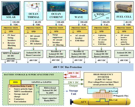
Figure 2.
Marine energy resources for WPT.

Table 1.
Comparison of ocean energy capacities [32,33,34,35,36,37,38,39,40,41,42].
Ocean thermal energy conversion (OTEC): OTEC has a high total annual power generation potential (44,000 JWh/year) but is still in the trial stage. Its efficiency is limited by the temperature difference between surface and deep ocean waters, typically around 20 °C, resulting in a low thermal efficiency of about 3–5%. OTEC has a relatively low environmental impact, but it can affect marine ecosystems by altering water temperatures and nutrient distribution [33]. OTEC is feasible for underwater applications, particularly in tropical regions with significant temperature gradients. However, the infrastructure required for deep-water intake and discharge is complex and costly [33]. Tidal power is more mature, with several commercial-scale developments. It has relatively high efficiency due to the predictability of tides, but the total annual power generation is lower (1200 JWh/year) compared to OTEC [34]. Tidal barrages can significantly impact local ecosystems by altering tidal flows and sediment transport, potentially affecting marine life [35]. Tidal power is highly feasible for underwater applications, especially in areas with strong tidal currents. The technology is well developed, but site selection is crucial to minimizing environmental impact. Wave energy has a wide range of potential power generation (8000 to 29,500 JWh/year) and is in the pilot plant stage. Efficiency varies based on wave height and frequency, with current technologies achieving around 20–50% efficiency [36]. If designed correctly, wave energy devices can have little effect on the environment, but they may still harm marine habitats and species [37]. Wave energy is also feasible for underwater applications, with various devices designed to operate below the surface.
However, the technology is still in the pilot stage, and further development is needed to improve reliability and efficiency. Salinity gradient power, also known as blue energy, harnesses the energy generated by the difference in salt concentration between seawater and freshwater. The theoretical global potential is estimated at 1650 JWh/year, but it is currently at the laboratory scale. The efficiency of salinity gradient power depends on the technology used, such as reverse electrodialysis (RED) or pressure retarded osmosis (PRO). PRO systems typically achieve efficiencies around 5–10%, while RED systems can reach up to 20–40% under optimal conditions [38]. Salinity gradient power has a relatively low environmental impact compared to other ocean energy sources. However, the mixing of freshwater and seawater can alter local salinity levels, potentially affecting aquatic life [39]. The discharge of brackish water back into the environment must be managed carefully to avoid disrupting marine habitats.
Marine current energy, also known as tidal stream energy, harnesses the kinetic energy of ocean currents. The total annual power generation potential is estimated at nearly 500 JWh/year, with some pilot plants already in operation. The efficiency of marine current turbines is relatively high, typically around 35–50%, depending on the design and strength of the current [40]. Marine current energy has a relatively low environmental impact, as the turbines are submerged and do not significantly alter water flow or sediment transport. However, there are concerns about the potential impact on marine life, particularly fish and marine mammals, due to noise and the risk of collision [41]. Proper site selection and turbine design can mitigate these impacts. Marine current energy is highly feasible for underwater applications, especially in areas with strong, predictable currents. The technology is well suited for deployment in deep water, and several pilot projects have demonstrated its potential [42]. Challenges include the high cost of installation and maintenance, as well as the need for robust materials to withstand harsh underwater conditions.
2.1. Wave Energy for Autonomous Underwater Vehicles (AUVs)
Wave energy, stemming from the transfer of wind energy to water, presents a significant global resource that holds promise for widespread energy production. Unlike solar and ocean thermal energy, wave energy is not constrained by geographical limitations and operates continuously. This makes it a versatile and sustainable option for electricity generation; this energy is supplied to the utility. The potential of wave energy is closely tied to sea conditions, including parameters like wave height and period. This variability means that different parts of the world can harness wave energy to varying degrees, offering flexibility in energy production strategies. Various devices have been designed and tested to capture and convert wave energy into usable electrical power. Among these, notable examples include oscillating body systems, oscillating water columns, overtopping devices, etc. Devices such as oscillating water columns or point absorbers can be scaled down and integrated into the structure of the battery storage unit. Wave energy provides a continuous and renewable power source. This capability extends mission duration significantly, enabling longer deployments for data collection or surveillance. This energy is used for the onboard charging of an AUV/hybrid glider for a long-term marine mission [43]. Wave energy is environmentally friendly, producing no emissions or pollutants during operation. This aligns with sustainable practices and minimizes the ecological footprint of the AUV mission. By harvesting wave energy, AUV can potentially operate over large areas without the need for frequent surface interventions. An extended-range wave-powered AUV with an average power of 10 W and a maximum instantaneous power capacity of 60 W was designed as a prototype and was tested successfully [44]. Energy storage plays a key role. Batteries or super capacitors are essential for storing surplus energy generated during peak wave conditions. Figure 3 shows the wave energy converter stored in the battery. This renewable energy source shows promise in powering various marine technologies, including AUVs, which are critical for ocean exploration, research, and surveillance without surface interruption [45].
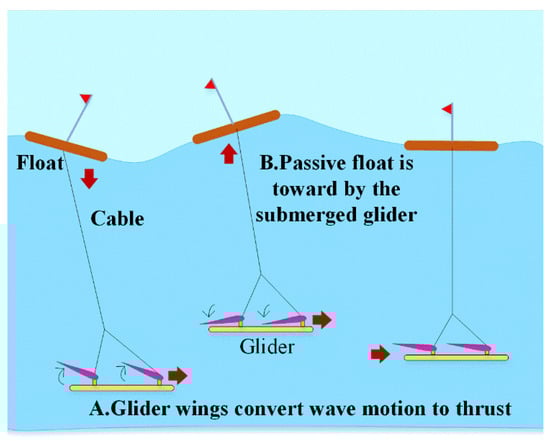
Figure 3.
Wave energy conversion.
According to referenced data [46], the OTE system can generate an average of 1.341 W of power without surface interruption [45], with a reported 60% efficiency during power generation. This energy output is sufficient to meet the operational needs of the AUV, including propulsion, sensors, and communication systems. The mechanical structure of the AUV is attached to the thermal energy conversion device.
2.2. Solar Power
Solar power is the cleanest and most abundant renewable energy source available. Solar power from the sun is converted into either thermal or electrical energy. Solar energy availability on the ocean surface varies significantly due to factors such as latitude, seasons, and weather conditions. Solar panels consist of photovoltaic (PV) cells that directly convert sunlight into electrical energy through the photovoltaic effect. Floating solar panels are commonly used to harvest solar energy. The efficiency of solar panels typically ranges from 10% to 12% in practical applications, and experimental models have achieved efficiencies of 20% to 25%. Per the NASA Surface Meteorological and Solar Energy (SSE) model, the recorded values were found to be correlated with the 22-year average worldwide solar radiation measurement. According to statistics collected from the ground, the annual average value of solar power across the globe is 17.98 MJ/m2 per day [47]. A solar-energy-fed AUV harnesses solar power to operate underwater without relying on external power sources. Solar panels are mounted on a buoy floating on the ocean surface. Advancements in solar technology allow for efficient energy conversion even in low-light conditions. The solar energy is harvested by the two photovoltaic panels, which generate a maximum power of 80 watts. It is stored in two lithium–iron–phosphate (LiFePO4) batteries to drive the AUV [10]. Two floating solar photovoltaic (PV) panels with a maximum power of 43 W were designed to power the AUV for a long single mission of 273 days [48]. Figure 4 shows the floating solar PV connected with a mooring cable to recharge the battery of an AUV. The total power of a solar panel was calculated from Equation (1) [39].
where Psolar represents solar power, ηsolar the efficiency, Asolar represents the surface area of solar panels, and Isolar represents solar irradiance, which is solar energy received per unit area.
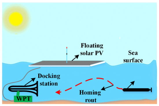
Figure 4.
Floating PV connected with a WPT system.
2.3. Wind Energy
Harnessing wind energy in the ocean, also known as offshore wind energy, has gained momentum as a promising renewable energy source. Wind speeds tend to be higher and more consistent over the ocean compared to on land, offering a more reliable source, and it has the potential to generate a significant amount of electricity. Floating turbine technology is being developed. These turbines are anchored to the seabed but float on the surface, enabling deployment in deeper and more remote locations. The generated electricity is stored in a primary battery to power the AUV. A prototype was developed for an autonomous surface vehicle to utilize wind energy [48]. The author proposed that endurance mileage and reliability of the driving scheme are improved by a hybrid system that powers the proposed unmanned surface vehicle (USV), which utilizes both solar and wind energy. The battery storage system is continually charged by the USV solar charging system and wind power. Table 2 shows the parameter of renewable energy resources.
Table 2.
Comparison of power density for various sources.
This system guarantees a long-term power supply for the control and monitoring systems, facilitating autonomous navigation and allowing for modifications to the sailing route in response to real-time wind conditions; excessive energy is stored in the lead–acid battery, the warm gear motor operates at 12 volts (V) and 1.5 amperes (A), and the system functions at a no-load speed of 9 rpm [49].
2.4. Fuel Cell
Fuel cells work like batteries, devices that generate electricity through an electrochemical reaction between a fuel, normally hydrogen, and an oxidizing agent, usually oxygen from the air. Fuel cells are well known for their high efficiency and environmental benefits. They produce electricity used in various applications, from large-scale power applications to small portable devices. Fuel cells are indeed a promising power supply for AUVs due to their high energy efficiency (typically 40–60%), which is an advantage for extending the operational range and endurance of AUV. Fuel cells in this range can provide sufficient continuous power; the range mentioned is 1 kW–4 kW [12], while batteries can handle intermittent peak power demand, and the above figure suggests the system is designed for moderate power requirements typical for AUVs.
Various types of fuel cells used to power AUVs [50], such as alkaline aluminum/hydrogen peroxide semi-fuel cells, and hydrogen fuel cells, were discussed. The surface boat contains two photovoltaic panels and a methanol fuel cell for the power management of an unmanned underwater vehicle (UUV), which is attractive. The fuel cell delivers 3.1 amperes, and the total power required is 9 amperes [10]. The Hugin 3000 (Kongsberg Maritime, Horten, Norway) AUV is powered by an alkaline aluminum/hydrogen peroxide semi-fuel cell that delivers 30 V/900 W, with a diving profile of 3000 m [51]. In Hugin II, the efficiency is only 65%, achieved with an alkaline Al/HP battery system and an alkaline aluminum/hydrogen peroxide semi-fuel cell [52]. Table 3 presents the specifications of different types of fuel cell stacks [12,53].
Table 3.
Types of fuel stacks used for AUV, UAV, and commercial stacks [53,54].
2.5. Primary and Secondary Battery
Batteries are compact, high-energy-density power sources used in homes, industries, and scientific research. They generate electrical energy when discharged and can be divided into two types based on their chemical processes and life cycles. Initial-stage AUVs are designed with non-rechargeable batteries because it is much safer and simpler, so they are straightforward to use and can deliver high energy density. This battery is not rechargeable, so its operational lifetime is limited. For every mission, AUV operating time was calculated based on the battery’s operational lifetime, which was selected accordingly. After every mission was completed, the installed battery was removed and replaced before the next assignment. Usually, primary batteries are alkaline batteries because they are available at an affordable price and have a large specific energy (200 Wh per kg); they will deliver a maximum power range up to 600 Wh/kg. For higher ratings, the size and weight will be limiting factors. For continuous underwater operations and survey operations, this battery was not suitable because replacing the battery will take up to half an hour, and bringing the AUV from underwater to surface level will take 2 to 3 h. Locum battery, Autosub-1, Seahorse-Alkaline cells, Spray glider, and Sea glider are typical primary batteries powering AUVs; data are from [14].
Rechargeable batteries are used as the secondary battery; they offer a long life of more than a thousand cycles. The rechargeable batteries include nickel metal hydride (Ni-MH), lithium–polymer (Li-Po), nickel–cadmium (Ni-Cad), lead–acid, and lithium-ion (Li-ion). Lithium-ion batteries occupy most of the applications because they offer high energy density and long battery life. Compared to lead–acid batteries, lithium-ion (Li-ion) weight was much less for the same rating, and charging a battery under low temperatures is quite challenging. Other types of batteries’ performance under hydrostatic pressure were comparatively low; in such conditions, lithium-ion (Li-ion) performed quite well, so it is most commonly used to power the AUV. HUGIN, Bluefin-9M (General Dynamics Mission Systems (formerly Bluefin Robotics), Quincy, MA, USA)—Pressure Li-Po, SEAGLIDER (Kongsberg Underwater Technology, Lynnwood, WA, USA)—Li-SO2Cl2, REMUS 100 (Huntington Ingalls Industries, Pocasset, MA, USA), Teledyne Gavia (Teledyne Gavia ehf, Kopavogur, Iceland)—Li-ion, Li-ion, and Sea Otter (ATLAS MARIDAN ApS, Otter, Norway)—NiMH are battery sources used for AUVs from the database [13]. Table 4 consists of the data for the different batteries used for AUVs. Table 5 represents the comparison and performance characteristics of secondary batteries. Different types of battery characteristics was presented in [50,55,56,57].
Table 4.
Typical performance Figures of the batteries for AUVs [50,55,56,57].
Table 5.
Comparison of the batteries [50,55,56].
2.6. Submerged Buoys for Underwater Applications
A UWPT system is often required for submerged buoys that are responsible for delivering energy. Buoys are equipped with power generation systems such as wave energy converters, solar panels, or underwater turbines. These systems convert renewable energy sources into electrical energy; this energy is converted and stored in the primary batteries of the buoy [58]. Figure 5 shows the structure of the buoy and its components. These systems enable the transmission of electrical power from a stationary buoy or use UWPT technology to transmit electrical power to an AUV. This technology allows for the transmission of electrical power from a stationary buoy to an underwater platform or moving or stationary AUVs without the need for physical connectors. The proposed buoy offers WPT with an efficiency of 70% and a capability of 10–20 volts [59]. The underwater platform can connect to various submerged devices or equipment without requiring a physical connection.
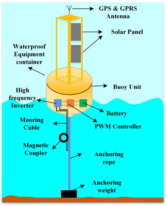
Figure 5.
Structure of the buoy.
3. Wireless Power Transfer System
The conception of WPT evolved from the idea of transferring power to an application without any physical connection through a wire from the source. WPT will be a user-friendly and effective power transfer; it will eliminate the plugging and unplugging of the cable to an application. Power is transferred with the help of classical fields: magnetic, electric, and electromagnetic fields. In the early 1900s, Nikola Tesla conducted a lot of research on WPT [60]. The transmitter coil is connected to power sources, and the receiver coil is connected to the load. Once the power source is turned on, the transmitter transmits the power to the secondary through any of the following fields: magnetic, electric, or electromagnetic. WPT is classified based on range and mode of power transfer: far-field, medium-field, and near-field charging. Existing wireless charging approaches utilize the medium field and near field. For inductive coupling power transfer, the use of different fields was very effective; medium-field charging was used for capacitive WPT, and the far-field method was suitable for radio waves, laser, and microwave power transfer. Figure 6 shows the classification of the WPT system. Figure 7 shows the efficiency curve of WPT for the far field and near field. The near field is a far more effective system compared to the other methods of WPT. Table 6 provides a comparison of different WPT systems, which can be less complex and transfer power for a longer distance.
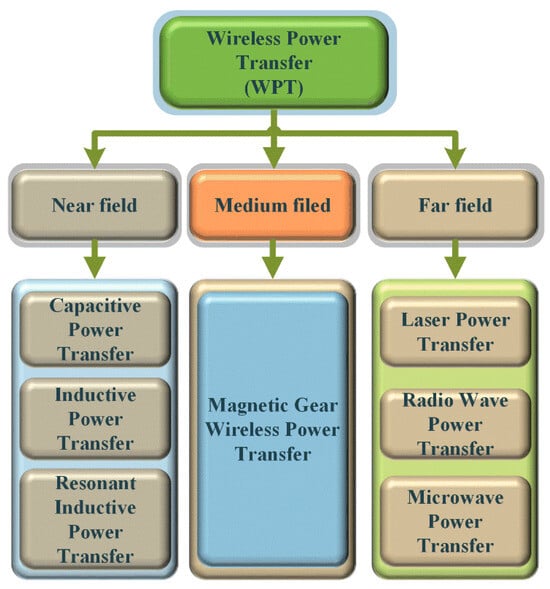
Figure 6.
Classification of WPT systems.
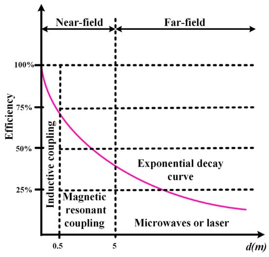
Figure 7.
Transfer efficiency of near- and far-field WPT system [61].
Table 6.
Comparison of various WPT systems.
It has been observed that the inductive and resonant inductive power transfer has high reliability over other WPT methods, with near-field WPT, such as inductive or resonant coupling, efficiently transmitting energy over short distances, making it well suited for charging AUVs at docking stations. However, its effectiveness depends on precise alignment, which can be difficult to maintain in the constantly shifting underwater environment. In contrast, far-field WPT methods, including acoustic and microwave-based approaches, allow for power delivery over greater distances. This provides more operational flexibility for AUVs since direct contact with a charging station is not required. WPT focuses on the distinctions between near-field and far-field methods, efficiency metrics, and coupling techniques. Near-field WPT involves short-range energy transfer through non-radiative methods like inductive coupling (with example efficiencies of 25% or a coupling coefficient of 0.5) and magnetic resonant coupling (possibly referencing a resonant frequency or distance metric, such as 5 MHz or 5 m). An exponential decay curve shows that these methods lose efficiency quickly as distance increases. In contrast, far-field WPT uses radiative approaches like microwaves or lasers for long-range power transfer, though these typically follow an inverse square law decay and suffer from lower efficiency. The slide also shows idealized efficiency benchmarks (100%, 75%, 50%) and a distance axis, d(m), which suggests a way to see how efficiency changes with range. In general, the content discusses the trade-offs between range, efficiency, and technology choices in wireless power systems. Near-field methods work best for short distances with high efficiency, while far-field methods work best for long distances with lower efficiency.
4. Underwater RIWPT Technology
4.1. Components of the RIWPT System
AUV underwater contactless charging is the most challenging; the resonant inductive wireless power transfer (RIWPT) technology is much more suitable for reliable operation. This system contains two devices, namely the docking system and the AUV. The docking system is used for charging the underwater vehicle. The AUV was designed to receive power from the primary side. AUVs’ secondary side consists of a receiver coil, a resonant circuit, an AC/DC power converter (rectifier), an output voltage regulator DC/DC converter, and a battery unit to store power. Figure 8 represents the block diagram of RIWPT system, and Figure 9 shows the equivalent circuit diagram of RIWPT system. RIWPT operation is similar to an electrical transformer; for transformer action, the AC supply is required, and from the available power, it is essential to create a high-frequency AC waveform to transfer power, and the inverter will take care of this function. The inverter is connected to a DC bus; it is powered by a DC/DC, AC/DC converter, DC generator, or other renewable energy source connected to the DC bus. A single-phase H-bridge inverter is commonly used to create an AC square wave with high frequency [7]. The resonant tank, primary coil, and secondary coil are designed to transmit and receive power, which will be converted by the output power converter, AC/DC, to deliver energy to the load. This area is very significant for the development of a better-performing RIWPT system. For low-power transfer and tightly coupled systems, non-resonant RIWPT is suitable. If the power rating and transmitting distance increase, resonant RIWPT is advisable for highly efficient power transfer. The primary and secondary consist of a core and coil. This design was taken from the transformer, with the core split into two parts, one placed in the docking system and the other placed in the AUV. The core provides a proper path for magnetic flux and good coupling between the primary and secondary coils. Shielding was necessary for all electronics and electrical applications to prevent the high-frequency magnetic field, and they dynamically modify output voltage or current. In the charging process of electric vehicles, three primary methods are employed: dual-side, secondary, and primary control [62]. Primary-side and double-side tuning methods are implemented with the help of bidirectional communication between the transmitter and receiver, while secondary control relies on rectifiers and DC/DC converters on the secondary side to regulate device operation. The wave trapper on the power receiver side resonates at a frequency of data transfer, while the wave trapper on the data transmitter side resonates at the frequency of power transfer, effectively minimizing crosstalk interference [30].
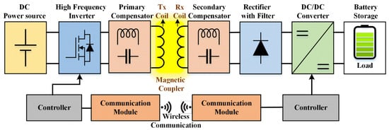
Figure 8.
Structure of the RIWPT system.
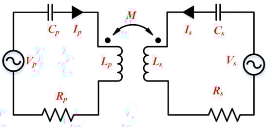
Figure 9.
Model based on the equivalent voltage source of the RIWPT system.
U1 is given in Equation (5) [63]. The coupling coefficient between secondary and primary coils is indicated by constant K, Q stands for the coil’s quality factor, and the resistance of both the transmitter Rt and receiver Rr coils are also considered.
In accordance with Kirchhoff’s voltage law, the voltage equation is written as
The output power of UWPT is expressed as
Here, is the receiver side’s load-dependent quality factor, written as .
Normally, the IPT system with SS compensator topology is designed to operate at a resonant frequency, i.e.,
where represents the system operating frequency, , are primary- and secondary-side resonant frequencies, respectively. Mutual inductance is defined in Equation (6).
4.2. Primary DC/DC Converter for Battery Storage
A WPT system consists of a high-frequency inverter. It requires constant DC power for the smooth operation of the inverter. Renewable energy sources cannot provide stable output power; however, interfacing with a high-performance DC/DC converter can ensure a stable power supply. The power stored in a battery will later be used for WPT operation when the AUV approaches the docking station. Table 7 provides the comparison of different DC/DC converters for storing energy in the battery.
Table 7.
Comparisons of the different DC-DC converters on the primary side.
4.3. Secondary DC/DC Converter for Battery Storage
Power received at the receiver coil is high-frequency AC, and this supply is fed to the power converter AC/DC. After this stage, a DC/DC converter is required for onboard charging of the battery, and the DC/DC converter was selected based on the mode of charging: constant current (CC) or constant voltage (CV). This study introduces a cooperative design approach for a buck converter to enhance the efficiency of UWPT (UWPT) systems while mitigating electrical stress on the inverter. A prototype of a 1 kW AUV, the UWPT system, is developed to authorize the proposed method. Additionally, results demonstrate that the integrated design method for the compensation network and DC/DC converter not only maintains a stable output voltage but also optimizes system efficiency to 91.1%, reduces inverter electrical stress, and facilitates zero-voltage switching of the inverter [27]. The real-time maximum power efficiency tracking (MPET) controller was designed for the buck converter and tested with the load variation of 20 ohms to 40 ohms [73]. To attain CC-CV charging for the AUV battery, a buck converter is used in [16]. The comparison of basic DC/DC converter topologies is given in Table 8. The author discussed the parallel-tuned pickup with the boost converter and the series-tuned pickup with the buck converter for a higher-capacity resonant inductive WPT system (RIWPT). The author discussed the merits of the buck–boost converter over the boost converter to charge the battery of the unmanned aerial vehicle (UAV) [6].
Table 8.
Charging output voltage and input resistance [16].
4.4. Front-End and Back-End Converter
The WPT system is made up of two separate parts: the primary side and the secondary side. When the load resistance is fairly low, well below the kilo-ohm range, a series–series configuration works better for delivering more power. The phase-shifted H-bridge inverter, a voltage source inverter (VSI), is widely used in WPT systems because of its high voltage utilization and straightforward design, effectiveness, and simplicity. Most commonly, series compensation is used to deduce the voltage ampere rating of the WPT system, which will be helpful in achieving soft switching for the converter. To maintain stable output power, a DC-DC converter is placed at the front end to control the input voltage (Vdc) of the primary-side inverter. Figure 10a shows the schematic. Depending on the application, this converter can be of the buck, boost, or buck–boost type. The author used a buck converter [20,25,28,74,75]. The primary front-end converter requires a DC supply voltage as an input from the AC supply connected to the grid. An AC supply from the grid is connected to an uncontrolled rectifier, then a DC link capacitor filters out the ripple, and then it is fed to a phase-shifted H-bridge inverter. A series compensation capacitor with the transmitter coil acts as a completer. In the transmitter section, a secondary coil connected with a series capacitor is present in the receiver section; the power is fed through the uncontrolled rectifier, and a DC-DC converter is most commonly used in the WPT system with a closed-loop control strategy to obtain the maximum power transfer efficiency [62,76].
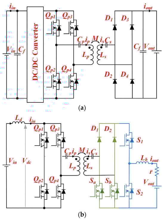
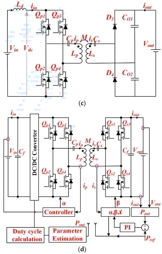
Figure 10.
UWPT with control system. (a) H-bridge inverter with uncontrolled rectifier, (b) H-bridge inverter with half-active rectifier, (c) H-bridge inverter with single-leg high-voltage rectifier, and (d) dual active bridge.
The author suggests a dual-receiver power control system. It uses a half-active bridge rectifier to handle two receiver coils and controls battery charging with a DC-DC converter in the secondary unit [77]. Figure 10b shows the circuit configuration of a half-active rectifier that has two diodes and two MOSFETs. The way the power controller is designed and managed is based on this dual-receiver setup and the DC-DC chopper model (buck converter), aiming to make the battery charging process as efficient as possible. The half-active rectifier operates in two modes, the rectification mode and the short-circuit mode.
A one-leg rectifier at the secondary stage with a buck converter as a voltage regulator was implemented by the author (Figure 10). Figure 10c shows the schematic single-phase voltage source inverter (VSI) topology with a coil connected between two legs of the H-bridge inverter to obtain the maximum power transfer efficiency. Implementing the soft-switching concept with the duty ratio of 0.5 achieved zero-voltage switching and zero-current switching at the same time. The one-leg rectifier is a simplified topology used in AC-DC conversion, particularly in applications where cost, size, and efficiency are critical; it reduces conduction loss and has bidirectional power flow capability with fewer switches [78,79,80].
The H-bridge inverter is connected to the transmitter, a secondary coil with a controlled rectifier known as a dual active bridge (DAB). It is a high-efficiency solution for WPT, enabling bidirectional power flow and soft-switching to minimize losses. It uses phase-shift modulation for precise control and works well with resonant networks, making it ideal for dynamic conditions like EV charging. While light-load efficiency drops, advanced modulation techniques improve performance with wide voltage range operation, low EMI, and high reliability, as seen in Figure 10. Figure 10d shows the DAB is a top choice for high-power WPT applications, and a bidirectional buck regulator connected to the controlled rectifier, which will regulate the desired output voltage of the battery charging system. This setup will ensure the bidirectional operation of the charging system. Grid-to-battery storage or battery-to-grid was implemented by the author with good efficiency [81,82,83]. Table 9 provides a comparison of different converter topologies for the transmitter and receiver sections.
Table 9.
Comparisons of the different topologies in WPT and UWPT.
Table 9.
Comparisons of the different topologies in WPT and UWPT.
| Primary Converter | Secondary Converter | Reference | Control Scheme | Number of Controlled Switches | Remarks |
|---|---|---|---|---|---|
| High-frequency H-bridge Inverter | Uncontrolled Rectifier | [20,25,28,62,74,75,76] | Frequency control and duty ratio control. | 4-(Transmitter), 0-(Receiver) | Primary-side control is only possible to regulate the output power. A simple control system is required to control power, cost-effective. |
| High-frequency H-bridge Inverter | Half-Active rectifier | [77] | Frequency control and firing angle control (rectifier). | 4-(Transmitter), 2-(Receiver), 2-(Buck Converter) | Primary- and secondary-side control is possible to regulate the output power with fewer active switches to obtain maximum efficiency. |
| High-frequency H-bridge Inverter | Single-leg rectifier | [78,79,80] | Frequency control and duty ratio control. | 4-(Transmitter), 0-(Receiver) | An effective method for higher voltage charging, the number of switches is lower |
| High-frequency H-bridge Inverter | Controlled Rectifier | [81,82,83] | Frequency control, duty ratio and firing angle control (rectifier). | 4-(Transmitter), 1-(Buck Converter) 4-(Receiver), | at the same time. Transmitter- and receiver-side converters are controlled to obtain maximum power transfer efficiency. Bidirectional operation is possible. Complex control, costlier. |
4.5. Underwater RIWPT Closed-Loop Control
Precise controller schemes are crucial for the efficient performance of the WPT system in charging the battery system. It is imperative to maintain high efficiency in WPT technology, as even a slight reduction in efficiency can result in substantial electric power losses. As an outcome, the primary-side control technique is used to optimize efficiency while regulating the output voltage and current. Two control parameters are usually required to attain these objectives: (a) modifying the output power or output voltage to align with the chosen reference, and (b) optimizing the voltage gain of the system or matching the impedance of the primary and secondary coil for high efficiency.
The system is fitted with power electronic converters on both the transmitter and receiver sides. Consequently, control strategies are typically classified as primary-side, secondary-side, and double-side control. Lower side frequency control (LFC) is shown in Figure 11a; note that in an open-loop WPT system, the output voltage tends to peak twice when the system is in an over-coupled state. As the operating frequency increases from zero up to a certain point, called the ωL peak, the voltage also goes up, reaching the first peak. Using this pattern, LFC adjusts the operating frequency to control and manage the output voltage more effectively. Higher side frequency control (HFC), unlike LFC, gradually increases the operating frequency starting from the point where the second peak (ωH peak) appears, theoretically pushing it toward infinity. As the frequency goes up, the output voltage naturally drops. Interestingly, both HFC and LFC use almost the same hardware and control methods. The key difference lies in their purpose: LFC is designed to achieve zero-current switching, while HFC is aimed at achieving zero-voltage switching (ZVS) in the inverter.
Figure 11.
UWPT closed-loop control schemes. (a) Lower side frequency control and higher side frequency control (HFC). (b) Primary-side duty ratio control. (c) Receiver-side duty ratio control. (d) Dual-side control.
The observer-free model predictive control MPC method uses the simplified refined instrumental variable (SRIV) data-driven modeling algorithm to handle the unknown dynamics of seawater with a conductivity of 4.9 S/m. It also uses the receding optimization nature of the MPC algorithm. Therefore, both excellent dynamic response characteristics and parametric robustness have been achieved within the highly conductive medium, with a horizontal misalignment of 0 mm and 100 mm. Load resistance, RL, varied from 10 ohm to 20 ohm, with a voltage fluctuation settling time of 9.3 ms [84]. The author uses a single-variable inductor as the PI controller’s actuator to control the output current of the underwater WPT systems. This approach obtains a high output power of 1 kW with an efficiency of 96.1%. However, no information is given on the dynamic response. The transfer distance is also only 14 cm, and the conductivity is only 3 S/m; once the conductivity increases, the system’s response may be affected [85]. Impedance matching is changed based on the distance of the transmission to make sure that the best power transfer happens.
To achieve this, an active impedance matching technique is used with a dual active bridge topology, dual-side control, and triple-phase-shift modulation. This work suggests a model predictive control (MPC) method for the active rectifier based on the model of the underwater wireless power transfer (UWPT) system. This method increases efficiency to 93.49% and cuts down on eddy current loss by 48.1%. The study, however, did not take into account the conductivity of saltwater. To check the dynamic response, the input voltage varied [86]. The author proposes a self-adaptive dual-channel de-tuned compensation topology to achieve a stable output for the wireless charging of autonomous underwater vehicles (AUVs). Within the low-coupling-coefficient interval of [0.2, 0.6], the system exhibits an output voltage fluctuation of only 8%. Notably, it can still maintain a transmission efficiency of over 89% in the worst-case scenario, while also achieving zero-voltage switching [87]. To maximize transmission efficiency and maintain constant current/voltage output under dynamic load impedance, the author proposes a bilateral control strategy that combines a robust fuzzy sliding mode control (FSMC) closed-loop system with automatic pulse width modulation. Furthermore, simulations at 100 kHz validate the impact of conductivity on eddy current losses, demonstrating the system’s consistent 88% efficiency in both seawater (3 S/m) and freshwater (0.01 S/m) environments [88].
4.6. Transmitting-Side Control
In this approach, the DC/AC converter on the transmitting side regulates the transmitter current. To effectively control the primary side relative to the load, it is essential to gather information from the receiving side, such as state of charge (SOC), battery voltage, and state of health (SOH). Without altering the operating frequency, the system’s output voltage can be linearly controlled by using a DC/DC converter on the transmitting side. Figure 11b shows that the input voltage ratio, defined as controller input, is equal to the ratio of Vo converter to Vin (input supply) and serves as the control parameter, where Vo converter is the output voltage of the DC/DC converter. The overall voltage gain of the system is determined by the product of the converter’s voltage gain and the voltage gain from the inverter input to the rectifier output. This strategy minimizes communication with the receiving side, which in turn reduces the number of onboard electrical components. As a result, the vehicle’s mass and cost should be lowered [89,90]. The receiving side’s operating frequency must match the frequency of the primary side. Consequently, the transmitter side is single-handedly responsible for satisfactory frequency regulations for the system. Inverters on the primary side can adjust both the operational frequency and the output by altering the number of turn-on and turn-off pulses per second [91,92]. To attain zero-voltage switching (ZVS), the working frequency needs to exceed the resonance frequency of the inductive impedance. Be aware that frequency splitting may happen, potentially resulting in multiple peaks [68].
4.7. Receiving-Side Control
We can place a DC/DC converter on the receiving side to control the output voltage. In this case, we use something called the load conversion ratio—the ratio between the converter input resistance and the load resistance—as the key factor. Figure 11c shows the difference from pre-regulation because the voltage gain from the inverter input to the rectifier output depends on this load conversion ratio. It is because the DC/DC converter changes the effective load resistance on the receiving side. It is more advantageous to have control over the receiving end of the infrastructure to optimize it. To regulate battery charging, this method employs a DC/DC regulator and an active AC/DC converter. Nevertheless, this results in an increase in the total weight of vehicles and cost as a result of the additional electrical devices for the pickup. A model was suggested to improve efficiency, controlling the power of the secondary side. Battery recharge current is directly regulated by a DC-DC converter in this technique. The system enhances power transfer capability by stabilizing the output DC voltage, thereby resolving the issue of DC terminal voltage instability [93,94]. The author suggested a wireless power and data transmission system to power electric vehicle (EV) batteries. The charging current will be adjusted by the controller to ensure the battery’s health and monitor the vehicle’s operational status. Nevertheless, this method is not appropriate for high-frequency carrier communications in low-power inductive power transfer (IPT) systems. It is preferable to have control over the receiving side to optimize the grounded infrastructure. This configuration incorporates a DC/DC regulator and an active AC/DC converter to regulate battery charging, resulting in an increase in vehicle weight and cost as a consequence of the additional electrical components.
A WPT device with a power rating of 3 kW is employed for recharging super capacitors in EVs. On the secondary side, the DC/DC buck converter equipped with a proportional–integral controller manages the charging current to accommodate load fluctuations. While the battery was in the process of charging, variations in the resistance R-equivalent of dissimilar power sources can affect both the battery charging rate and the overall enactment of the device [80]. The author proposed that the DC/DC converter on the secondary side is solely responsible for controlling output voltage, while the AC/DC converter on the receiving side manages impedance matching. The effectiveness of the proportional–integral control versus fuzzy logic control for buck–boost converters was compared in the article [95].
4.8. Dual Control
The dual control method requires the management of a WPT system from both the primary and secondary sides (Figure 11). Figure 11d shows that the strategy is based on the link between primary and secondary control. Although the desired outcome can be achieved with control on only one side, optimal performance cannot be guaranteed. Consequently, it is advisable to implement dual-side control to effectively achieve these objectives [96]. A dual-sided control with improved efficacy was presented in [97]. The voltage control technique was a multifaceted concept that has been implemented on any component of the system, including output voltage regulation, pulse density modulation (PDM), and phase-shift pulse control technique. Using DC/DC converters, DC voltage regulation entails the adjustment of input voltage on the transmitter side of the inverter or output voltage of the rectifier on the receiver side. The phase differences between individual converters must be altered to achieve phase-shift control. While this approach may outperform DC voltage regulation in terms of speed, it may not be practicable to achieve zero-voltage switching (ZVS) conditions. On the other hand, the PDM technique is designed to modify the RMS voltages by adjusting the number of pulses. The currents and power of the WPT system should be regulated by altering the phase shift of the pulse between the inverter leg voltages of a single converter and the voltages of both converters. The phase difference (α) between two segments of the primary-side inverter is established by the primary-side controller. The output voltage of the inverter is adjusted to align with the rated current of a primary circuit by adjusting this parameter (α). Meanwhile, the secondary-side controller is regulated by the phase difference (β) between the legs of the secondary-side converter and the phase difference (δ) between the output voltages of the two converters [89].
4.9. Compensation Topology
The coils in WPT systems exhibit high leakage inductance and loose coupling, which requires the use of a compensation circuit to reduce the apparent power ratings and required supply power (Figure 12). Figure 12 shows the basic and hybrid compensation topology. Compensators were initially employed exclusively on either the primary or secondary side [21]. Nevertheless, to optimize performance and increase efficiency, both the receiver and transmitter sides must implement effective compensation for coils with substantial loose coupling [8].
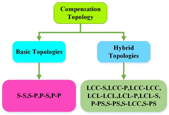
Figure 12.
Classification of compensators.
The fundamental approach entails the addition of capacitors on both sides to account for leakage inductance. Figure 13 illustrates four primary compensation types: series–series (SS), series–parallel (SP), parallel–parallel (PP), and parallel–series (PS), which are contingent upon the configuration of capacitors with the coils. If the SS/SP topology is employed, the voltage source inverter [VSI] should be directly connected to the primary coil. However, if the system is parallel–series (PS) or parallel–parallel (PP), an inductor is typically connected to convert it to [CSI]. Capacitors on both sides are designed using the resonance equation ω_0 = 1⁄√LC. As outlined in [98], it is crucial to sustain a consistent current in the transmitter coil. Series compensation at the receiver end generates an output that resembles a voltage source (VS), while parallel compensation generates an output that resembles a current source (CS). However, fluctuations in the current input may deviate from these conventional characteristics. The capacitor on the transmitter side is typically calibrated to guarantee that input voltage and current are in phase under particular loads and coupling conditions to minimize apparent power in the converter. This method is frequently referred to as the zero-phase angle (ZPA) method. The compensator on the transmitter side is typically altered to incorporate a small amount of reactive power. The objective of this modification is to attain zero-current switching (ZCS) or zero-voltage switching (ZVS) conditions, per the ZPA method. Table 10 specifies the capacitance values necessary to satisfy the ZPA condition for each specific topology in [90]. Maximum efficiency and optimal power transfer are achieved in all configurations when the working frequency matches the resonant frequency, especially when high-quality factor coils are utilized. Table 10 presents a comparison of basic compensation techniques operating at the frequency ωo with unity input power factor. In some cases, the transmitter compensation capacitor, Cp, is selected not only to compensate for transmitter coil inductance but also for the reflected reactance, which reduces the VA rating of the system power supply. As shown in Table 10, the primary compensation capacitance Cp remains consistent in series-compensated primaries (SS and SP) regardless of the load. However, in parallel-compensated primaries, Cp changes with the load, which makes it impossible to achieve a zero-phase angle under all load conditions.
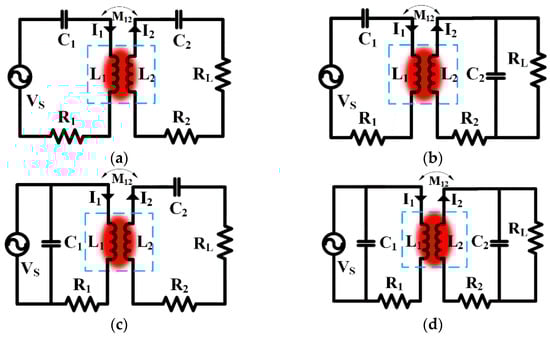
Figure 13.
Basic single-element compensation techniques. (a) SS, (b) SP, (c) PS, and (d) PP.
The predominant method for charging batteries in most AUVs involves the use of constant current. In these situations, SP compensation is the optimal solution because of its current source-like characteristics when supplying the load. Series–series (SS) and series–parallel (SP) compensations will effectively decrease power supply voltages at handleable levels. SS compensation ensures the output current is not dependent on the load, whereas SP compensation ensures the voltage output is not dependent on the load when a system is operating at the resonance frequency ωo. However, these methods are at risk in situations where the receiver coil is absent without load or during slight load conditions, which can result in voltage source short circuits or current source open circuits (SP). The combined planar receiving coil is proposed with SS compensation; the dual setup increases power from 401.23 W to 417.89 W under misalignment conditions of 0–40 mm [19]. LCC compensation, in particular, is distinguished by its widespread application, which provides a robust tolerance to misalignment and load variations while simultaneously reducing current (I) stress on inverter switches.
Additionally, the output of the current source should be effectively regulated by the inverter to account for fluctuations in load conditions and coupling coefficient (K). The dual-sided LCC technique offers a solution for the mitigation of current surge disadvantages by reducing mutual inductance, unlike the SS topology. Consequently, the dual-sided LCC technique has the potential to equal or exceed the maximal transmission power of the S-S topology [7,19]. The author proposed a multi-load receiver coil structure with LCC-LCC to attain the constant current on the secondary side [5,17,22,99]. Although it was possible to maintain either CV or CC output, the sophisticated arrangement of its receiver side, as well as the massive compensating inductor, placed additional weight on the AUV. The LCC-S topology network is employed in system design to achieve both weight reduction in the receiver on the AUV and to satisfy the battery’s requirements for constant voltage or constant current output [20,94]. The author proposed a 2 kW prototype, which includes LCC-S. The findings indicate that the coil structure’s performance remains unaffected under rotation misalignment but is influenced by radial movement and axial movement [100]. An H-bridge inverter is connected with the LCC circuit to the primary coil, and series compensation is added to the secondary coil. An AC/DC converter and filter capacitor were employed to provide DC voltage to the DC/DC step-down converter; it regulates the DC voltage to attain constant current or constant voltage (CC/CV) battery charging for the AUV [16]. Constant current is achieved by the LCC-P topology [25]. Table 10 provides the compensator topology used for wireless power transfer for an AUV. Figure 14 shows the hybrid compensation topologies of RIWPT system.
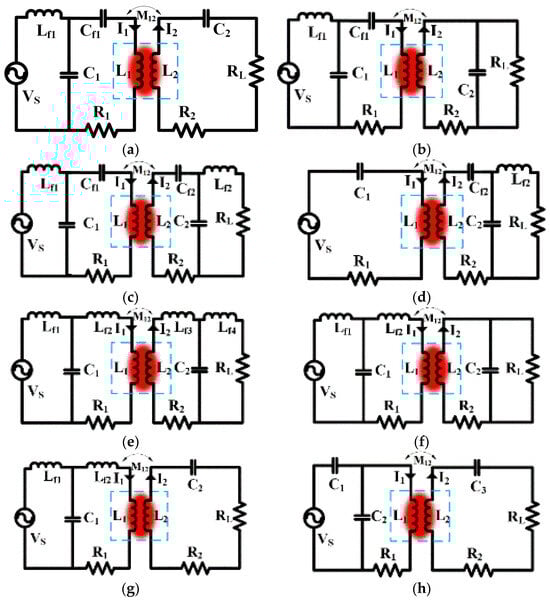
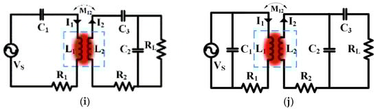
Figure 14.
Multiple element hybrid compensation techniques. (a) LCC-S, (b) LCC-P, (c) LCC-LCC, (d) S-LCC, (e) LCL-LCL, (f) LCL-P, (g) LCL-S, (h) SP-S, (i) S-PS, and (j) P-PS.
Table 10.
Comprehensive compensation of different parameters of basic topology [8,101].
Table 10.
Comprehensive compensation of different parameters of basic topology [8,101].
| Topology | Primary Capacitance | Bifurcation Criteria | Quality Factor | Reflected Resistance and Reactance | Output Characteristics |
|---|---|---|---|---|---|
| S-S | Re, Im | CC operation acts as a voltage source at the receiving side | |||
| S-P | Re, Im | CV operation acts as a current source on the secondary side | |||
| P-S | Re, Im | CV operation acts as a Voltage source at the receiving side | |||
| P-P | Re, Im | CC operation acts as a Voltage source at the secondary side |
5. UWPT Magnetic Coupler for AUV
5.1. Magnetic Couplers’ Design Requirements
Numerous critical challenges arise when designing a magnetic coupler for UWPT to guarantee reliable performance in challenging underwater environments. The coupler must be entirely waterproof and capable of reliable operation in varying pressures and harsh environments while also being protected against water ingress, corrosion, and biofouling. Optimizing the magnetic field coupling between the transmitter and receiver coils is essential to reduce energy loss during transmission, which necessitates efficiency. Compatibility with extant structures and the reduction of bulk are essential for integration with underwater vehicles, which necessitates compactness and a lightweight structure. The coupler must be mechanically robust and durable over extended periods without performance degradation, as the harsh underwater environment is influenced by currents, detritus, and impacts. To ensure continuous, efficient power transmission without constant adjustment, it is essential to have a high tolerance for misalignment, which is due to the potential movement of underwater vehicles. To prevent interference and guarantee safe operation in the presence of other electronics and external electromagnetic fields, it is essential to adhere to rigorous electromagnetic compatibility (EMC) standards. To ensure optimal performance in various temperature conditions and to extend the operational lifespan, it is essential to implement effective heat dissipation strategies. Hydrodynamics must be considered during the integration process to reduce drag and maintain operational efficiency in the vehicle’s structure and mooring stations. It is imperative to comply with the safety standards and regulations that govern underwater equipment [20], which incorporate operational reliability, environmental impact, and electrical safety in various scenarios. In conclusion, creating a magnetic coupler for UWPT requires a careful balance between practical factors like size, weight, and ease of integration, and technical factors like efficiency and compliance with EMC standards. By satisfying these requirements, underwater vehicles and systems that operate in challenging marine environments are guaranteed reliable and efficient power transfer capabilities.
5.2. Magnetic Coupler (MC) for RIWPT System
The structured coil with dipole-based MC was designed for resonant inductive wireless power transfer (RIWPT) charging of an AUV, which was designed to attain a constrained magnetic field distribution and reduced weight compared to an annular (MC) magnetic coupler. Fe-based nanocrystalline lenient magnetic material was used to implement the MC, and its performance was similar to that of ferrite material. The wireless charging system with dipole (MC) achieved a high-power transfer of 633.47 W, and with DC-DC efficiency, it is 89.67% in seawater when fully aligned [7]. The author designed an 80 kW WPT for AUV, which will charge the battery at 10 °C, and built a scaled-down 5.18 kW prototype of the system that achieved better performance in saltwater with better efficiency. The method demonstrated outstanding tolerance to a rotational misalignment of 360 degrees and retained better efficiency across the wide power range [94]. Self-latching coupling assembly for UWPT addresses the challenges of attenuation in seawater and resistance to ocean current disturbance, and validate the system through a 3 kW experiment that achieves 92% DC/DC efficiency with a 5 mm gap [94]. A 360° folded spatial unipolar magnetic couple structure significantly decreases the leakage magnetic field into the internal area of the AUV, mitigating EMI impacts on onboard electronic devices. A prototype demonstrated 5 kW power transfer in saltwater. The coupler maintained 82.9% efficiency at well aligned power, even with 360° rotational misalignment [25]. A trumpet-shaped structure is proposed that is compatible with the construction of AUV and prevents rotational misalignment, enabling stable and efficient WPT up to 2 kW.
The arc-molded underwater wireless charging magnetic coupler using Fe-based nanocrystalline alloy material as the magnetic core can achieve a lightweight design and transmit 3 kW power at 91.9% DC/DC efficiency when well aligned. The designed UWPT system can maintain high efficiency at 90.59% and 90.19% DC/DC efficiency even with 30 mm axial and 10° rotational misalignment. The 86 kHz operating frequency will effectively suppress the additional eddy current loss (ECL) caused by seawater, allowing the system to perform similarly in seawater and air [99]. For the motor similarity type (ring type), a new coil structure is proposed, where the decoupled receiver coils maintain stable mutual inductance despite rotational misalignment. This allows the system to increase by up to 664 W with 92.26% DC/DC efficiency in the best case and 485 W with 92.10% efficiency in the worst case of 22.50 misalignment [17]. The curly DD/DD arc bipolar transmitter and the dipole coil-based receiver are designed to be fixed into the surface and have a less lightweight secondary coil, providing stability with better charging performance. The proposed MC utilizes an arc bipolar primary coil and a small dipole coil-based secondary coil to create strong and steady coupling during misalignment. This system was capable of delivering a constant 11 A and a constant voltage of 54 V and has better interoperability for AUVs with various diameters and with different power levels, delivering up to 1.05 m KW [16]. The trumpet-shaped design proposed was well suited to the structure of the AUV, preventing misalignment under a high degree of rotation and enabling stable and efficient WPT up to 2 kW [100]. For the segmented arc solenoid transmitter coil multi-load, the WPT system was proposed with a ring-shaped receiver coil, the transmitter coil was constructed as a segmented arc solenoid to produce a strong magnetic field, and the nearby coil was wound reversely to strengthen the electromagnetic field and improvised coupling with receivers. A 1000 W prototype was presented, and it achieved 500 W output power; results were discussed for each receiver under different angles between the receivers [5]. A two-part reverse-wound receiver was proposed as a rotating resilient wireless charging system, which substantially enhanced the system performance in the presence of rotational misalignment. The proposed idea was verified through finite element analysis and circuit analysis, and a prototype was constructed and tested. The experimental result indicated that the output power was continuous, ranging from a maximum of 745 watts to a minimum of 321 watts under rotational misalignment. Additionally, the output power could be enhanced by utilizing customized arc-shaped magnets [22]. This paper proposed a solenoid primary coil, and a double combined planar secondary coil was proposed to enhance the misalignment tolerance of WPT systems for AUV. This coupling assembly maintained more consistent transmission power and efficiency compared to a unipolar planar coil coupling arrangement that was solenoid when axial misalignment occurred.
The efficiency of power transfer and variation in output power in the WPT system with the proposed coupling structure was lower compared to the solenoid unipolar planar coil assembly under axial misalignment conditions. Experimental outcomes confirmed that the highest output power achieved is 1.05 kW; in saltwater, the proposed design efficiency decreased from 85.04% to 78.3% [19]. An overlapped direct quadrature DQ transmitter and dipole receiver was proposed, which has a small volume and a lightweight receiver. A space–time coordination mechanism was presented to form a constant traveling wave, stabilizing the efficiency and output power against rotational and axial misalignment. The developed prototype can deliver 1200 watts to the load with an efficiency of 90%; even in misalignment conditions of [−30 mm, 30 mm] in both axial dislocation and rotational dislocation, the current and system efficiency can remain stable [102]. A U-shaped bipolar coil transmitter and an arc-shaped unipolar receiver can offer a better range of rotation misalignment tolerance compared to previous designs. An experimental prototype was built for 600 watts at 85 kHz; the author proposed a magnetic coupling structure that has simple controls and can achieve magnetic field enhancement by having the transmitter and receiver coils with opposite polarity. Experimental results show that the proposed design maintains a stable output power of around 500 watts, with a wide rotation angle of 240° rotation, with maximum fluctuations of 4.35% for output power and 2.34% for efficiency under load variations from 10 to 50 ohms [26].
Bipolar and unipolar magnetic coil structures can be used for power and data transmission, respectively, to create perpendicular magnetic fluxes. Orthogonal receiver coils are in a superimposed mode to receive the perpendicular fluxes. The use of wave trappers in the data channel attenuate interference from the power channel. DPSK modulation is used for data transmission. The receiver was designed to compact 741 g, and it can deliver 936 W output power [103]. The proposed system can deliver 964.7 W. The quadruple coil transmitter and crossed dipole receiver design can handle rotational misalignment of −20° to 20° with a maximum output power fluctuation of 12.1%. The system can handle axial misalignment of −30 to 30 mm with a max output power fluctuation of 20.2% [104]. Table 11 shows the types if magnetic coupler and it performance characteristic such as operating frequency, gap between the primary secondary coil of an AUVs, misalignment rotation angle of the different couplers, the system efficiency of the system in detail. Table 12 shows the different types of AUVs with profile.
Table 11.
Classification of magnetic couplers and their characteristics.
Table 12.
AUV profile.
A variable ring-shaped magnetic coupler was developed by the author, which can change the size of the transmitter to fit the receiver, increasing the output power of the WPT system for AUV. Using the variable ring-shaped magnetic coupler, the output power of the 800 W WPT system increased by 69.47 W (9.1%). The power density of the WPT system increased by 9.6% to 1.6 W/g after using the variable ring-shaped magnetic coupler [20]. The proposed ID-shaped magnetic coupler with a pendulum-type receiver achieves high efficiency (95.985% dc-dc) and a high-power density of over 3000 watts while being lightweight (746 g). The magnetic coupler design provides a high tolerance to rotational and axial misalignment of up to +30 mm to −30 mm. The proposed magnetic coupler design is more compact and has higher receiver power density compared to various UWPT magnetic coupler designs, making it promising for future engineering applications [114]. A hybrid transmitter composed of conical and planar spiral coils was proposed, which greatly improves the misalignment tolerance and transfer performance. Experiments indicated that the hybrid transmitter had 23.6% and 16.2% better power stability compared to planar spiral and helix transmitters, respectively. At a transfer distance of 2 cm, the hybrid transmitter output power increased by only 5.7%, even with misalignment [115]. Over the years, industries and researchers have been working extensively to develop AUVs for tasks like underwater exploration, environmental monitoring, mapping the ocean floor, inspecting pipelines, and military missions. Each AUV is designed with specific power needs, depth capabilities, and operational strengths to suit different challenges. To better understand how these vehicles perform, Table 12 AUV profile and Table 13 break down key details like energy consumption, endurance, and diving limits. They also compare different AUV models, highlighting their advantages, drawbacks, and practical uses. Another exciting development is the potential use of WPT, which has the potential to revolutionize the industry by enabling AUVs to recharge without the need for physical connections, thereby significantly increasing their mission time and efficiency. Figure 15a,b shows the different profile such as efficiency, misalignment tolerance, power density, design complexity and interoperability of magnetic couplers.
Table 13.
Comparison of AUV models: efficiency, feasibility, and key factors.
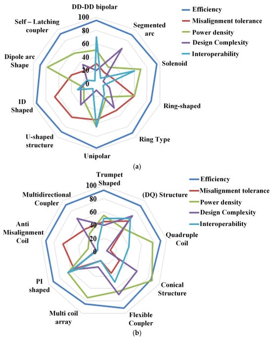
Figure 15.
(a,b) Magnetic coupler attribute profile.
6. The Effect of Seawater Medium on UWPT Systems
In a WPT system, the fundamental influence of seawater as a transmission medium is determined by a variety of important factors, including permeability, permittivity, and conductivity. These considerations have a substantial impact on the optimal operating frequency, system output characteristics, and overall performance. Table 14 summarizes the electrical properties of various media. Different effects present in the deep-sea environment affect WPT performance, especially disturbance, temperature, water pressure, permittivity, and conductivity. This section deals with the various effects that affect the performance of WPT.
Table 14.
Electromagnetic parameters for different media [25].
6.1. Seawater Conductivity
Eddy current losses are an inevitable consequence of the WPT system’s operation in an underwater environment. The performance of the WPT system is adversely affected by the considerable increase in eddy current loss that occurs underwater, even though the difference between air and pure water is minimal. As frequency and coil current increase, eddy current loss (ECL) tends to increase. Consequently, it is imperative to establish strategies to reduce ECL, such as the development of precise measurement techniques for UWPT systems, which can serve as a theoretical foundation for enhancing transmission efficacy. A variety of methods have been proposed to address ECL, such as the optimization of coil structures, the modification of current and frequency control techniques, and the utilization of corresponding circuit models [28]. In [116], it was suggested to use a modified mutual inductance circuit model to examine how seawater affects WPT by causing eddy current loss (ECL) and de-tuning effects. The system introduces the concept of equivalent eddy current loss impedance (EECLI) to account for the ECL caused by seawater and finds that ECL increases significantly with higher resonant frequencies. It was found that seawater causes de-tuning of the transmitter side of the WPT system, and a phase difference between the transmitter and receiver coil currents was no longer than 90 degrees due to different conductivities. Efficiency is decreased due to the eddy current in the presence of seawater compared to air, from 90% to 80%. Eddy current loss in the underwater WPT system is expressed in Equation (8) [116]. The eddy current loss caused by the primary coil is calculated in [117] Equation (9). The author discussed that the eddy current loss in seawater sharply increases with rising resonant frequency, which shifts the optimum resonant frequency in seawater to a smaller value compared to that in air. The optimum operating frequency of a WPT system in seawater should be larger than the resonant frequency to achieve the maximum DC/DC efficiency [118].
The appropriate resonance frequency for underwater WPT systems depends on the coil gap, seawater conductivity, and eddy current; hence, optimizing transmission efficiency was discussed. Transmission efficiency is highest and total loss of transfer power is lowest when the operational frequency is somewhat higher than the resonance frequency. Moreover, turn density, size, and misalignment are the coil characteristics affecting the ideal frequency. In Figure 16b, the author shows the various losses present in the high-power RIWPT system with varying input voltage [119]. Due to eddy current losses caused by an alternating magnetic field, the transmission efficiency of a WPT system operating in saltwater will be reduced, as the conductivity of seawater is higher than that of freshwater. Figure 16a shows the result of eddy current power loss for different frequencies. The overall system eddy current is expressed in Equation (7). The total eddy current is written as (8).
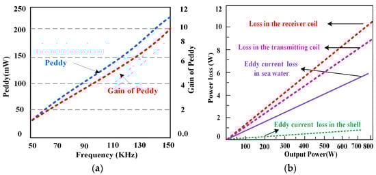
Figure 16.
(a) The eddy current loss variation with frequency [25], (b) eddy current and other losses concerning different voltages [25].
The primary-coil-side eddy current loss is expressed in Equation (8).
The primary-coil-side and secondary-coil-side eddy current losses are expressed in Equation (9).
When the operating frequency goes beyond a specific limit, AEC loss surpasses core and winding losses, becoming the main constraint on LCT transmission efficiency in seawater [28]. For the variable ring-shaped magnetic coupler, the magnetic coupler enables seamless contact between the AUV and the platform during charging, aligning the AUV’s posture to enhance power efficiency and ensure a stable transmission process [20]. Figure 17 shows the equivalent circuit of eddy current loss present in the sweater environment.
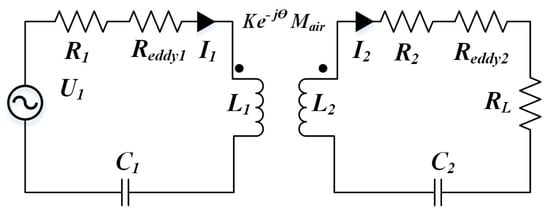
Figure 17.
Modified equivalent circuit for eddy current.
6.2. Ocean Current Interference
Seawater currents have a notable effect on the performance of WPT systems, as they can cause misalignment between transmitters and receiver coils. Many studies have investigated the creation of couplers to tackle the difficulties presented by seawater currents. Traditional magnetic couplers used in WPT systems often consist of various designs, including different mechanical structures like rectangular, circular, and solenoid, which are represented in Table 11. A solenoid-type variable ring structure with rotational freedom and least-sensitive misalignment was proposed [20]. Figure 18 shows the AUVs open type docking station.
Figure 18.
Docking systems of an unclosed dock [100].
Despite these advancements, conventional designs often require extra shielding and stabilization due to their vulnerability to ocean currents. Thus, it is necessary to optimize these structures to increase their ability to withstand ocean currents, minimize alignment problems, and tackle the challenges of cost, physical property, and completeness in WPT systems. Table 11 shows a comparative analysis of different underwater WPT (UWPT). During the AUV docking process, the secondary coil aligns with the primary coil, allowing electric power to be transferred from the submerged base station to the AUV [23]. The drawbacks of the typical torpedo-shaped under-actuated AUV were discussed, and the merits of different cone-shaped docking stations were discussed [120]. The closed docking and unclosed docking stations’ merits and demerits were discussed, and the degree of misalignment between the docking and AUV was lower.
6.3. Biofouling
Wet surfaces generally attract microorganisms, leading to their accumulation, a phenomenon known as biofouling. A key issue with WPT systems in marine environments is biofouling, which arises from the accumulation of marine microorganisms on the water surface. To reduce the formation of biofouling, various studies and experiments have been conducted to apply ultrasound waves in the range of 1.5 kHz to 200 kHz for 40 s, which have been effective in various proposals [31]. This issue is particularly problematic in resonant inductive WPT systems, as it can disrupt the alignment between transmitter and receiver coils and increase the gap between them. Consequently, the system’s power transfer efficiency diminishes. To mitigate biofouling, external heat treatments and anti-fouling paints are commonly used. Designing and sealing electromagnetic couplers in deep-sea environments can be quite challenging due to the immense pressure of seawater. Important considerations involve selecting suitable materials and performing a comprehensive structural analysis. The housing and sealing materials need to remain stable and withstand corrosion caused by exposure to seawater for a long duration. In addition, the transmitter and receiver need to have a seamless alignment while also being able to withstand the turbulent conditions often encountered at significant depths. In addition, it is essential to consider electromagnetic interference (EMI). Figure 19 shows the biofouling in equipment under the seawater environment.

Figure 19.
Biofouling on vessel hull [31].
6.4. Temperature
Because of its exceptional magnetic characteristics, low temperatures, and high-frequency performance, soft magnetic ferrite is a perfect material for WPT systems. This is because of the combination of these three factors. To maximize the effectiveness of power transfer in WPT applications, certain characteristics are necessary. Temperatures in submarines tend to decrease as the depth of the vessel increases, and they might fluctuate unpredictably. The temperature coefficient of ferrite is a measurement that determines the change in permeability that occurs between two given temperatures. This coefficient is used to quantify the temperature stability of ferrite. The temperature coefficient is given by the change in permeability between two fixed temperatures, as seen in Equation (10).
where is the permeability at temperature and is the permeability at temperature .
6.5. Pressure
The author deals with the effect of hydrostatic pressure up to 1500 bar on the permeability of ferrite material. The magnetic core is exposed to high hydrostatic pressure to observe relative permeability variation [120]. Figure 20 shows the relationship between pressure and hysteresis. As the pressure increases, the hysteresis will increase. High pressure decreases the magnetic permeability of ferrite due to its piezomagnetic properties. This relationship between the initial permeability and pressure is represented by the following Equation (11) [121].
μrc (0) and μrc (P) represent the relative permeability of the ferrite core in an ambient atmosphere and under pressure P, respectively, while K denotes a constant associated with the ferrite.
Figure 20.
Pressure-induced hysteresis [102].
As atmospheric pressure rises to 40 MPa, the permeability of ferrite materials decreases by over 40%. The average permeability is expressed in Equation (11), where the pressure underwater rises by one atmosphere for every 10 m of depth.
In deep-sea environments, where pressures can reach up to 40 MPa, the magnetic core, which is exposed to seawater, experiences a reduction in relative permeability to approximately 1400. Based on Equation (12) [121], as the magnetizing inductance, Lm, decreases, the reluctance will correspondingly increase. Due to the variation in the salinity of seawater, conductivity increases; this causes variation in the flux density [122]. Figure 21 shows the coupling coefficient variation while varying the gap between transmitter and receiver coil in horizontal as well as vertical direction. Figure 22 shows the relationship between the magnetizing inductance and the gap variation between transmitter and receiver coil of WPT system.
Figure 21.
Coupling efficiency as a function of gap length [103,123,124].
Figure 22.
Performance of EM coupler in atmosphere and 40 MPa pressure water [122,125].
6.6. Effect of the Hull
The hull’s material and the shape of the metal plates impact the high-operating-frequency alternating electromagnetic fields, and high-working-frequency alternating electric fields interact in inductive and capacitive wireless power transfer (CWPT) systems. The placement of metal plates (rectangular or curved) inside the coupled assembly of the underwater WPT system can prevent power transfer and affect the electromagnetic field and electric fields. The power transfer capacity of the underwater capacitive wireless power transfer (UCWPT) system is less affected by the metal plates compared to UWPT. The UWPT system can enhance its power transmission capacity and reduce electromagnetic interference (EMI) noise by placing metal plates external to the coupled assembly [126]. The mutual inductance, transmitter, and receiver coil inductance vary with the presence and the location of the plate [127]. The various parameters associated with the magnetic and electrical properties of the metal aluminum are permeability 0.999991, conductivity 58,000,000, and a relative dielectric constant of 1; for copper, permeability is 1.000021, conductivity is 38,000,000, and relative dielectric constant is 1; and for iron, permeability is 4000, conductivity is 10,300,000, and relative dielectric constant is 1.
7. Engineering Design Challenges of an UWPT System for AUV
7.1. UWPT Control Strategy and Data Transfer Strategy
Generally, the control schemes for the WPT system should be adjusted through key aspects, such as AC/DC converter control, compensation circuit control, AC/DC converter control, and DC/DC converter control. Dual control schemes will require greater control to achieve satisfactory efficiency. In one switching cycle, the power control transistor and data transfer control transistor are complementarily turned on and off to alternately deliver power and data using the FSK modulation technique [30]. A superimposed dual-frequency modulation technique is used for WPT with a single inverter [127]. A high-speed full-duplex communication with a maximum data rate of 700 kb/s is used to effectively reduce the stress on the data channel [29] and a model predictive control strategy is implemented with LCC-S for the regulation of output power [128].
7.2. RIWPT System Implementation on an AUV
Incorporating the RIWPT system into an AUV while maintaining its shape and hydrodynamic efficiency presents a significant challenge. The hull of the AUV is made from lightweight, mechanically robust, and conductive materials, such as aluminum and titanium. In [106], the secondary coil was positioned within the aluminum hull of the AUV, leading to a notable decrease in power transfer efficiency compared to configurations that did not include the hull. Several previous designs [23,24,28] modified the AUV’s shape by incorporating projections that extend beyond the hull, which could influence the hydrodynamic performance of the AUV. Conversely, the coaxial coil design in [60] incorporates a slender secondary coil affixed to the hull, maintaining the AUV’s form while producing an increased magnetic flux within the vehicle.
7.3. Interoperability
The current docking stations are designed for specific types of AUV hulls, which means that they cannot be reused as AUV technology advances. For example, the early docking stations built at WHOI to recharge the REMUS 100 will not work with the larger REMUS 600, as mentioned in [84], and the dock mooring system [4] cannot be used together because they are made for specific sizes. However, the LCWT-based IWPT system is a bit of an exception, as it can charge multiple AUVs of different sizes at the same time. In the end, making sure that different systems can work together is one of the most important goals for future AUV wireless charging technology.
7.4. Battery Charging Rate
Factors such as ambient temperature, operational speed, and thermal conditions influence the performance of a battery [125,129]. The quick charging of AUVs becomes challenging due to the lower ambient temperatures in marine environments, which reduce the maximum charging and discharging rates of subsea batteries. Consequently, most commercially available pressure-tolerant underwater batteries are restricted to discharge rates under one C, which limits mission duration. At sea level, the subsea temperature is 25 °C, but it drops to 0 °C at a depth of 4 km. The study in [125] describes pressure-tolerant LiPo battery tests conducted across various temperatures (3 to 25 °C) and pressures (0.1–50 MPa). The results show that pressure changes have a minimal impact on battery resistance and capacity. In contrast, lower ambient temperatures lead to a significant increase in resistance and a reduction in capacity. A further analysis of how low temperatures affect electrochemical processes within Li-ion batteries is discussed in [130]. At colder temperatures, batteries experience reduced electrolyte conductivity, slower charge transfer, increased resistance at the solid electrolyte interface, and reduced lithium diffusion through surface layers [129]. A tenfold rise in resistance occurs when the temperature drops from 25 °C to 20 °C. However, the resistance increase is temporary, returning to normal once the temperature rises and electrolyte conductivity improves [131].
7.5. Least Misalignment of Couplers
Tackling the issue of anti-misalignment poses a considerable obstacle in the territory of WPT technology, specifically in the domain of UWPT (UWPT). The design strategies for addressing anti-misalignment in UWPT systems involve various important aspects. These involve the incorporation of docking stations and mechanical alignment mechanisms, the creation of non-misalignment magnetic couplers (MCs), the utilization of misalignment-adaptive system topologies, and the use of control over the stability of those methods to address misalignment problems. The article [23] presents a unipolar magnetic couple that shows that the rotational misalignment was not possible in the primary and secondary assembly of a cylinder, and the experimental setup shows effective power transfer with 96% efficiency. A U-shaped bipolar coil transmitter and an arc-shaped unipolar receiver, which complement each other’s field enhancement properties, are designed to achieve a broad range of rotation misalignment tolerance (RMT). Additionally, the proximity of the transmitter and receiver coils contributes to their effectiveness [26]. A hybrid transmitter design that integrates conical and planar spiral coils has been developed, significantly enhancing both misalignment tolerance and transfer efficiency [115]. This coupler is designed in a way that decreases misalignment and enhances the WPT system’s capacity for power transfer.
7.6. Selection of Ferrite Core
Understanding the importance of ferrite cores in enhancing magnetic flux is key to maximizing energy transfer efficiency between primary and secondary coils. With their notable magnetic permeability and low electrical conductivity, core losses like eddy currents and hysteresis are kept to a minimum, resulting in reduced energy loss as heat. By improving the effective magnetic permeability of the core, ferrites greatly amplify the inductance of the coils. This enhanced inductance improves the coupling between the coils of the transmitter and receiver. Ferrites are classified as soft ferrites, powdered ferrites, and ceramic ferrites. These types are specifically designed for high-frequency applications because they have negligible core losses at high frequencies. For high-power applications, ferrites provide exceptional thermal stability and a high saturation flux density. Choosing the right ferrite core for your wireless power system is crucial, as different ferrite materials are designed to work optimally within specific frequency ranges.
A refined magnetic coupler incorporating ferrite cores and a magnetic shielding structure is introduced to enhance power transfer stability and efficiency. Unlike traditional planar-shaped ferrite core couplers, the proposed design minimizes ferrite material usage without compromising the performance of the WPT system [100]. The size and shape of the core have a major impact on the efficiency of the system. When selecting a ferrite core, it is important to choose one that can handle the power levels without saturating. It is also important to consider its thermal properties to manage heat effectively in high-power applications [132]. The performance graph for relative magnetic permeability under temperature variation for a ferrite material is made by mixing elements such as Fe, Mn, Zn, and Co. Table 15 provides different percentages of the elements to make a ferrite bar. Figure 23 and Figure 24 shows a wide range of variation in relative magnetic permeability with respect to temperature variation.
Table 15.
Properties of different ferrite materials [132,133].
Figure 23.
Magnetic permeability of MnZn ferrite [132].
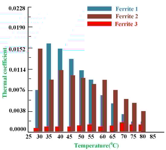
Figure 24.
Thermal stability of MnZa ferrite [132].
The thermal coefficient’s response varies with temperature. The amount of iron, manganese, zinc, and cobalt added to make the ferrite will change the magnetic property. Thus, the selection of ferrite material is also important for the WPT system [123,132].
8. Guide to Best Practices for Developing an IWPT System for AUVs
This section outlines general recommendations for designing an underwater inductive WPT (IWPT) system for AUV charging. The selection between an inductive coupler based on the loosely coupled transformer principle or a resonant IWPT system depends on the minimum gap achievable between the primary and secondary coils. When the gap is small (a few centimeters), inductive couplers provide higher efficiency, better field confinement, and reduced electromagnetic interference. However, they require a retention system to maintain a consistent gap. For gaps ranging from 1 to 20 cm or when misalignment is likely, resonant coils are more suitable due to their greater tolerance to misalignment. Determining the ideal operating frequency is still a challenge. Although earlier research suggests a general range (50 kHz to 200 kHz) of frequency, its exact value depends on various design-specific factors. These include the dimensions and configuration of the couplers, the spacing between the magnetic components, and the influence of surrounding materials such as ferrite or metal. Therefore, the optimal frequency is not a one-size-fits-all value and must be calculated for each unique design. Such an outcome can be achieved through either finite element method simulations or experimental testing, depending on the application’s requirements.
A metallic hull structure around the pad can disrupt WPT and lower the system’s efficiency. If it is not possible to avoid using a metallic hull, designing a ferrite field-shaping structure around and behind the coils can help reduce stray fields and enhance efficiency. Metallic hulls, on the other hand, have less impact on inductive couplers because they naturally provide better field confinement. Choosing an appropriate compensation network is another crucial consideration for resonant IWPT systems. The hybrid compensation topology offers significant advantages for fast-charging the batteries of AUV. By combining a mix of traditional and advanced power management strategies, this approach optimizes the charging process. It effectively blends active and passive compensation techniques to ensure efficient power transfer and precise control over charging parameters. As a result, AUVs benefit from quicker charging times. Elements such as the temperature of the battery and biofouling on the pad’s surface can have a significant influence on system performance. To ensure that the battery stays at a higher temperature, a more advanced design could be considered that harnesses the heat generated by WPT converter losses to warm the battery module. To combat biofouling, it is important to periodically activate the charging units, which will heat the pad’s surface and help eradicate microorganisms, plants, algae, and other types of growth.
Summary WPT Applications
Wireless power transfer technology has attracted wide research and industrial attention beyond underwater applications due to its ability to deliver power without cable-based connection, reliability, improved safety, and lower maintenance needs with better efficiency. In smart manufacturing and industrial automation, WPT is widely used to power rotating machines, automated guided vehicles (AGVs), robotic arms, and conveyor systems, excluding wear-prone slip rings and supporting continuous operation in moving or harsh environments. In the EV sector, wireless charging systems were developed for static and dynamic types of passenger cars, buses, and other heavy vehicles, supporting automated charging, enhanced user convenience, and reduced exposure to high-voltage contacts. In biomedical and healthcare industries, WPT enables the reliable powering of implantable biomedical devices, surgical tools, and wearable sensors, where physical connections pose infection risks. The Internet of Things (IoT) and industrial sensor networks also benefit considerably from WPT, especially through near-field inductive and resonant inductive or far-field radio frequency energy harvesting, permitting the long-term, battery-storage-free operation of distributed sensors in smart manufacturing plants and hazardous locations. Furthermore, WPT is applied in defense and aerospace sectors for the driving of embedded sensors and unmanned aerial vehicles, as well as in consumer and logistics industries for the wireless charging of mobile devices, drones, and smart packaging. Collectively, these applications validate that WPT is a key enabling technology for future-generation industrial applications requiring flexibility, robustness, and maintenance-free operation, providing a resilient motivation for continued research into high-power, high-efficiency, and multi-source integrated wireless power transfer frameworks.
Underwater sensing networks and long-term seabed or moored sensor nodes are among the most feasible and high-impact applications of underwater wireless power transfer (UWPT). These systems play a vital role in observing ocean environments, tracking environmental behavior, inspecting offshore structures, and supporting defense and scientific applications. Since these sensors are often located in deep or inaccessible underwater locations, frequently replacing batteries or retrieving the devices for charging is often costly, time-consuming, and sometimes impossible. UWPT offers an effective solution by allowing energy to be delivered wirelessly. UWPT allows underwater sensors to operate for much longer periods with minimal maintenance. This is especially valuable for moored sensors and seabed applications, where a stable power supply helps guarantee continuous data collection and reliable communication. Removing wired connectors also makes the system more durable by dropping the problems caused by biofouling, corrosion, and mechanical damage in marine environments. Generally, UWPT makes underwater sensing networks more reliable and suitable for the long-term autonomous operation of the application.
9. Conclusions
AUVs are being utilized for both military missions and ocean exploration at an accelerated pace. Inductive wireless power transmission (IWPT) has been proposed as a solution to the range and autonomy limitations of AUVs, which are a result of their limited onboard energy storage. This article thoroughly examines IWPT systems specifically designed for use with AUVs. The article describes how a basic IWPT system framework works, how it is controlled, and how power is transmitted to the AUV. When designing these systems to work efficiently in seawater, engineers must take into account unique problems, such as the effects of eddy current. The article primarily addresses the influence of temperature, pressure, biofouling, and seawater conductivity. In addition, the technical challenges are addressed, including the integration of inductive WPT modules with the hull of the AUV, proper alignment, data transmission, and then an underwater closed-loop control system to attain highly efficient power transmission for the WPT system. The article concludes with recommendations and best practices for the development of efficient IWPT charging systems for AUVs. Furthermore, the article addresses the importance of additional developments in the IWPT system.
Author Contributions
R.S. contributed to conceptualization, methodology, investigation, data curation, and writing of the original draft. N.R. contributed to the methodology, formal analysis, validation, supervision, and writing—review and editing. H.Z.A.G. contributed to the formal analysis, resources, and validation. J.A. contributed to the validation, resources, and manuscript review. A.E. contributed to conceptualization, project administration, supervision, and writing—review and editing. All authors have read and agreed to the published version of the manuscript.
Funding
This research received no external funding.
Data Availability Statement
The datasets used and/or analyzed during the current study are available within the manuscript.
Conflicts of Interest
The authors declare that there are no conflicts of interest.
Abbreviations
The following abbreviations are used in this manuscript:
| AUV | Autonomous underwater vehicle |
| WPT | Wireless power transfer |
| EV | Electrical vehicle |
| SAUV | Solar-powered autonomous underwater vehicle |
| PV | Photovoltaic panel |
| UWPT | Underwater wireless power transfer |
| RIWPT | Resonant inductive wireless power transfer |
| SOC | State of charge |
| SOH | State of health |
| USV | Unmanned surface vehicle |
| LFC | Lower side frequency control |
| HFC | Higher side frequency control |
| ZVS | Zero-voltage switching |
| SSE | Surface meteorological and solar energy |
| OTEC | Ocean thermal energy conversion |
| RED | Reverse electrodialysis |
| PRO | Pressure retarded osmosis |
| DPST | Double-pole single-throw |
| FSK | Frequency shift keying |
| S-S | Series–series |
| PS | Parallel series |
| UAV | Underwater autonomous vehicle |
| PME | Proton exchange membrane |
| FLC | Fuzzy logic controller |
| MPPT | Maximum power point tracking |
| P&O | Perturb and observe |
| M | Mutual inductance |
| K | Coupling coefficient |
| Q | Quality factor |
| P | Power |
| Rt | Transmitter coil resistance |
| Rs | Receiver coil resistance |
| U | Voltage |
| ECL | Eddy current losses |
| Tx | Transmitter |
| Rx | Receiver |
| Mn | Manganese |
| Fe | Iron |
| Zn | Zinc |
References
- Sahoo, A.; Dwivedy, S.K.; Robi, P.S. Advancements in the field of autonomous underwater vehicle. Ocean Eng. 2019, 181, 145–160. [Google Scholar] [CrossRef]
- Crimmins, D.; Deacutis, C.; Hinchey, E.; Chintala, M.; Cicchetti, G.; Blidberg, D. Use of a long endurance solar powered autonomous underwater vehicle (SAUV II) to measure dissolved oxygen concentrations in Greenwich Bay, Rhode Island, U.S.A. In Proceedings of the Europe Oceans 2005, Brest, France, 20–23 June 2005; Volume 2, pp. 896–901. [Google Scholar] [CrossRef]
- Crimmins, D.M.; Patty, C.T.; Beliard, M.A.; Baker, J.; Jalbert, J.C.; Komerska, R.J.; Chappell, S.G.; Blidberg, D.R. Long-Endurance Test Results of the Solar-Powered AUV System. In Proceedings of the OCEANS 2006, Boston, MA, USA, 18–21 September 2006; pp. 1–5. [Google Scholar] [CrossRef]
- Stokey, R. Enabling technologies for REMUS docking: An integral component of an autonomous ocean-sampling network. IEEE J. Ocean. Eng. 2001, 26, 487–497. [Google Scholar] [CrossRef]
- Yan, Z.; Zhang, K.; Qiao, L.; Hu, Y.; Song, B. A Multiload Wireless Power Transfer System with Concentrated Magnetic Field for AUV Cluster System. IEEE Trans. Ind. Appl. 2022, 58, 1307–1314. [Google Scholar] [CrossRef]
- Fares, A.M.; Klumpner, C.; Sumner, M. A Novel Multiport DC-DC Converter for Enhancing the Design and Performance of Battery–Supercapacitor Hybrid Energy Storage Systems for Unmanned Aerial Vehicles. Appl. Sci. 2022, 12, 2767. [Google Scholar] [CrossRef]
- Cai, C.; Zhang, Y.; Wu, S.; Liu, J.; Zhang, Z.; Jiang, L. A Circumferential Coupled Dipole-Coil Magnetic Coupler for Autonomous Underwater Vehicles Wireless Charging Applications. IEEE Access 2020, 8, 65432–65442. [Google Scholar] [CrossRef]
- Li, S.; Mi, C.C. Wireless power transfer for electric vehicle applications. IEEE J. Emerg. Sel. Top. Power Electron. 2015, 3, 4–17. [Google Scholar] [CrossRef]
- Kutkut, N.H. Design Considerations for Power Converters Supplying the SAE 5-1773 Electric Vehicle Inductive Coupler. In Proceedings of the Applied Power Electronics Conference, Atlanta, GA, USA, 27 February 1997; Volume 2, pp. 841–847. [Google Scholar] [CrossRef]
- García-Córdova, F.; Guerrero-González, A. Intelligent navigation for a solar powered unmanned underwater vehicle. Int. J. Adv. Robot. Syst. 2013, 10, 185. [Google Scholar] [CrossRef]
- Chan, C.C. The state of the art of electric and hybrid vehicles. Proc. IEEE 2002, 90, 247–275. [Google Scholar] [CrossRef]
- Farahabadi, H.B.; Firuzjaei, M.R.; Mir, A.M.; Youneszadeh, R. Fuel Cell Power System Conceptual Design for Unmanned Underwater Vehicles Article Information. Fuel Cell Energy Storage 2023, 10, 33–50. [Google Scholar] [CrossRef]
- D’AMORE-Domenech, R.; Raso, M.A.; Villalba-Herreros, A.; Santiago, Ó.; Navarro, E.; Leo, T.J. Autonomous underwater vehicles powered by fuel cells: Design guidelines. Ocean Eng. 2018, 153, 387–398. [Google Scholar] [CrossRef]
- Wang, X.; Shang, J.; Luo, Z.; Tang, L.; Zhang, X.; Li, J. Reviews of power systems and environmental energy conversion for unmanned underwater vehicles. Renew. Sustain. Energy Rev. 2012, 16, 1958–1970. [Google Scholar] [CrossRef]
- Rynne, P.F.; von Ellenrieder, K.D. A wind and Solar-Powered Autonomous Surface Vehicle for sea surface measurements. In Proceedings of the OCEANS 2008, Quebec City, QC, Canada, 15–18 September 2008; pp. 1–6. [Google Scholar] [CrossRef]
- Cai, C.; Wu, S.; Zhang, Z.; Jiang, L.; Yang, S. Development of a Fit-to-Surface and Lightweight Magnetic Coupler for Autonomous Underwater Vehicle Wireless Charging Systems. IEEE Trans. Power Electron. 2021, 36, 9927–9940. [Google Scholar] [CrossRef]
- Yan, Z.; Song, B.; Zhang, Y.; Zhang, K.; Mao, Z.; Hu, Y. A Rotation-Free Wireless Power Transfer System with Stable Output Power and Efficiency for Autonomous Underwater Vehicles. IEEE Trans. Power Electron. 2019, 34, 4005–4008. [Google Scholar] [CrossRef]
- Joseph, P.K.; Elangovan, D. A review on renewable energy powered wireless power transmission techniques for light electric vehicle charging applications. J. Energy Storage 2018, 16, 145–155. [Google Scholar] [CrossRef]
- Wen, H.; Wang, P.; Li, J.; Yang, J.; Zhang, K.; Yang, L.; Zhao, Y.; Tong, X. Improving the Misalignment Tolerance of Wireless Power Transfer System for AUV with Solenoid-Dual Combined Planar Magnetic Coupler. J. Mar. Sci. Eng. 2023, 11, 1571. [Google Scholar] [CrossRef]
- Zhang, B.; Chen, J.; Wang, X.; Xu, W.; Lu, C.; Lu, Y. High-Power-Density Wireless Power Transfer System for Autonomous Underwater Vehicle Based on a Variable Ring-Shaped Magnetic Coupler. IEEE Trans. Transp. Electrif. 2024, 10, 3061–3074. [Google Scholar] [CrossRef]
- Kim, D.; Kim, H.; Huang, A.; He, Q.; Zhang, H.; Ahn, S.; Zhu, Y.; Fan, J. Analysis and introduction of effective permeability with additional air-gaps on wireless power transfer coils for electric vehicle based on SAE J2954 recommended practice. Energies 2019, 12, 4797. [Google Scholar] [CrossRef]
- Kan, T.; Zhang, Y.; Yan, Z.; Mercier, P.P.; Mi, C.C. A Rotation-Resilient Wireless Charging System for Lightweight Autonomous Underwater Vehicles. IEEE Trans. Veh. Technol. 2018, 67, 6935–6942. [Google Scholar] [CrossRef]
- Mostafa, A.; Wang, Y.; Zhang, H.; Tangirala, S.; Lu, F. An Ultra-Fast Wireless Charging System with a Hull-Compatible Coil Structure for Autonomous Underwater Vehicles (AUV). In Proceedings of the 2022 IEEE Transportation Electrification Conference and Expo, ITEC 2022; Institute of Electrical and Electronics Engineers Inc.: New York, NY, USA, 2022; pp. 279–284. [Google Scholar] [CrossRef]
- Qiao, K.; Sun, P.; Rong, E.; Sun, J.; Zhou, H.; Wu, X. Anti-misalignment and lightweight magnetic coupler with H-shaped receiver structure for AUV wireless power transfer. IET Power Electron. 2022, 15, 1843–1857. [Google Scholar] [CrossRef]
- Qiao, K.; Rong, E.; Sun, P.; Zhang, X.; Sun, J. Design of LCC-P Constant Current Topology Parameters for AUV Wireless Power Transfer. Energies 2022, 15, 5249. [Google Scholar] [CrossRef]
- Chen, Z.; Zhang, X.; Xu, F.; Li, M.; Yuan, Z.; Yang, Q. Wide Rotation-Misalignment-Tolerance Design of Magnetic Coupled Structure for AUV Wireless Charging System. IEEE Trans. Ind. Electron. 2024, 71, 14086–14096. [Google Scholar] [CrossRef]
- Liu, Z.; Li, F.; Tao, C.; Li, S.; Wang, L. Design of wireless power transfer system for autonomous underwater vehicles considering seawater eddy current loss. Microsyst. Technol. 2021, 27, 4783–4792. [Google Scholar] [CrossRef]
- Cheng, Z.; Lei, Y.; Song, K.; Zhu, C. Design and Loss Analysis of Loosely Coupled Transformer for an Underwater High-Power Inductive Power Transfer System. IEEE Trans. Magn. 2015, 51, 8401110. [Google Scholar] [CrossRef]
- Wang, Y.; Li, T.; Zeng, M.; Mai, J.; Gu, P.; Xu, D. An Underwater Simultaneous Wireless Power and Data Transfer System for AUV with High-Rate Full-Duplex Communication. IEEE Trans. Power Electron. 2023, 38, 619–633. [Google Scholar] [CrossRef]
- Yang, L.; Huang, J.; Feng, B.; Zhang, F.; Zhang, Y.; Li, X.; Jian, J.; Wang, Z.; Tong, X. Undersea Wireless Power and Data Transfer System with Shared Channel Powered by Marine Renewable Energy System. IEEE J. Emerg. Sel. Top. Circuits Syst. 2022, 12, 242–250. [Google Scholar] [CrossRef]
- Legg, M.; Yücel, M.K.; De Carellan, I.G.; Kappatos, V.; Selcuk, C.; Gan, T.H. Acoustic methods for biofouling control: A review. Ocean Eng. 2015, 103, 237–247. [Google Scholar] [CrossRef]
- Marine Energy—Wikipedia. Available online: https://en.wikipedia.org/wiki/Marine_energy (accessed on 22 August 2024).
- Vega, L.A. Ocean Thermal Energy Conversion Primer. Mar. Technol. Soc. J. 2002, 36, 25–35. [Google Scholar] [CrossRef]
- Charlier, R.; Finkl, C. Ocean Energy: Tide and Tidal Power; Springer: Berlin/Heidelberg, Germany, 2009. [Google Scholar] [CrossRef]
- Kadiri, M.; Ahmadian, R.; Bockelmann-Evans, B.; Rauen, W.; Falconer, R. A review of the potential water quality impacts of tidal renewable energy systems. Renew. Sustain. Energy Rev. 2012, 16, 329–341. [Google Scholar] [CrossRef]
- Falnes, J. A review of wave-energy extraction. Mar. Struct. 2007, 20, 185–201. [Google Scholar] [CrossRef]
- Boehlert, G.W.; Gill, A.B. Environmental and ecological effects of ocean renewable energy development: A current synthesis. Oceanography 2010, 23, 68–81. [Google Scholar] [CrossRef]
- Post, J.W.; Veerman, J.; Hamelers, H.V.; Euverink, G.J.; Metz, S.J.; Nymeijer, K.; Buisman, C.J. Salinity-gradient power: Evaluation of pressure-retarded osmosis and reverse electrodialysis. J. Memb. Sci. 2007, 288, 218–230. [Google Scholar] [CrossRef]
- Yip, N.Y.; Tiraferri, A.; Phillip, W.A.; Schiffman, J.D.; Elimelech, M. High performance thin-film composite forward osmosis membrane. Environ. Sci. Technol. 2010, 44, 3812–3818. [Google Scholar] [CrossRef] [PubMed]
- Couch, S.; Bryden, I. Tidal current energy extraction: Hydrodynamic resource characteristics. Proc. Inst. Mech. Eng. Part M-J. Eng. Marit. Environ. 2006, 220, 185–194. [Google Scholar] [CrossRef]
- Gill, A.B. Offshore renewable energy: Ecological implications of generating electricity in the coastal zone. J. Appl. Ecol. 2005, 42, 605–615. [Google Scholar] [CrossRef]
- Fraenkel, P.L. Marine current turbines: Pioneering the development of marine kinetic energy converters. Proc. Inst. Mech. Eng. Part A J. Power Energy 2007, 221, 159–169. [Google Scholar] [CrossRef]
- Fenucci, D.; Caffaz, A.; Costanzi, R.; Fontanesi, E.; Manzari, V.; Sani, L.; Stifani, M.; Tricarico, D.; Turetta, A.; Caiti, A. WAVE: A wave energy recovery module for long endurance gliders and AUV. In Proceedings of the OCEANS 2016 MTS/IEEE, Monterey, CA, USA, 19–23 September 2016; pp. 1–5. [Google Scholar] [CrossRef]
- Li, H.; Wu, X.; Zhang, Z.; Tan, X.; Pan, Y.; Dai, C.; Luo, D.; Ahmed, A.; Xu, Y. An extended-range wave-powered autonomous underwater vehicle applied to underwater wireless sensor networks. iScience 2022, 25, 104738. [Google Scholar] [CrossRef]
- Chao, Y. Autonomous underwater vehicles and sensors powered by ocean thermal energy. In Proceedings of the OCEANS 2016—Shanghai, Shanghai, China, 10–13 April 2016; pp. 1–4. [Google Scholar] [CrossRef]
- Zhang, H.; Ma, X.; Yang, Y. An External Ocean Thermal Energy Power Generation Modular Device for Powering Smart Float. Energies 2022, 15, 3747. [Google Scholar] [CrossRef]
- Mohammad, S.T.; Al-Kayiem, H.H.; Aurybi, M.A.; Khlief, A.K. Measurement of global and direct normal solar energy radiation in Seri Iskandar and comparison with other cities of Malaysia. Case Stud. Therm. Eng. 2020, 18, 100591. [Google Scholar] [CrossRef]
- Hine, R.; Willcox, S.; Hine, G.; Richardson, T. The Wave Glider: A Wave-Powered autonomous marine vehicle. In Proceedings of the OCEANS 2009, Biloxi, MS, USA, 26–29 October 2009; pp. 1–6. [Google Scholar] [CrossRef]
- Zhou, X.Q.; Ling, L.; Ma, J.; Tian, H.; Yan, Q.; Bai, G.; Liu, S.; Dong, L. The design and application of an unmanned surface vehicle powered by solar and wind energy. In Proceedings of the 2015 6th International Conference on Power Electronics Systems and Applications (PESA), Hong Kong, China, 15–17 December 2015; pp. 1–10. [Google Scholar] [CrossRef]
- Hasvold, Ø.; Størkersen, N.J.; Forseth, S.; Lian, T. Power sources for autonomous underwater vehicles. J. Power Sources 2006, 162, 935–942. [Google Scholar] [CrossRef]
- Hasvold, O.; Johansen, K.H. The alkaline aluminium hydrogen peroxide semi-fuel cell for the HUGIN 3000 autonomous underwater vehicle. In Proceedings of the 2002 Workshop on Autonomous Underwater Vehicles, 2002, San Antonio, TX, USA, 21 June 2002; pp. 89–94. [Google Scholar] [CrossRef]
- Hasvold, Ø.; Johansen, K.H.; Mollestad, O.; Forseth, S.; Størkersen, N. The alkaline aluminium/hydrogen peroxide power source in the Hugin II unmanned underwater vehicle. J. Power Sources 1999, 80, 254–260. [Google Scholar] [CrossRef]
- Mendez, A.; Leo, T.J.; Herreros, M.A. Current state of technology of fuel cell power systems for autonomous underwater vehicles. Energies 2014, 7, 4676–4693. [Google Scholar] [CrossRef]
- Horizon XP PEM Fuel Cell—500W. Available online: https://www.fuelcellstore.com/horizon-xp500-watt-pem-fuel-cell (accessed on 22 August 2024).
- Bluefin 1.5 kWh Subsea Battery—General Dynamics Mission Systems. Available online: https://gdmissionsystems.com/products/underwater-vehicles/bluefin-robotics/1-5-kwh-subsea-battery (accessed on 23 June 2024).
- Projects—Ned Forrester. Available online: https://www.whoi.edu/staff/nforrester/project-auv-li-ion-battery-systems (accessed on 22 August 2024).
- Ocean Power—SubCtech—Ocean Power & Monitoring. Available online: https://subctech.com/ocean-power/ (accessed on 22 August 2024).
- Fang, C.; Li, X.; Xie, Z.; Xu, J.; Xiao, L. Design and optimization of an inductively coupled power transfer system for the underwater sensors of ocean buoys. Energies 2017, 10, 84. [Google Scholar] [CrossRef]
- Xu, J.; Li, X.; Li, H.; Xie, Z.; Ma, Q. Maximum Efficiency Tracking for Multitransmitter Multireceiver Wireless Power Transfer System on the Submerged Buoy. IEEE Trans. Ind. Electron. 2022, 69, 1909–1919. [Google Scholar] [CrossRef]
- Zhong, W.; Lee, C.K.; Hui, S.Y.R. General analysis on the use of tesla’s resonators in domino forms for wireless power transfer. IEEE Trans. Ind. Electron. 2013, 60, 261–270. [Google Scholar] [CrossRef]
- Jawad, A.M.; Nordin, R.; Gharghan, S.K.; Jawad, H.M.; Ismail, M. Opportunities and challenges for near-field wireless power transfer: A review. Energies 2017, 10, 1022. [Google Scholar] [CrossRef]
- Orekan, T.; Zhang, P.; Shih, C. Analysis, Design, and Maximum Power-Efficiency Tracking for Undersea Wireless Power Transfer. IEEE J. Emerg. Sel. Top. Power Electron. 2018, 6, 843–854. [Google Scholar] [CrossRef]
- Hasan, K.; Ahmad, S.; Liaf, A.F.; Karimi, M.; Ahmed, T.; Shawon, M.A.; Mekhilef, S. Oceanic Challenges to Technological Solutions: A Review of Autonomous Underwater Vehicle Path Technologies in Biomimicry, Control, Navigation, and Sensing. IEEE Access 2024, 12, 46202–46231. [Google Scholar] [CrossRef]
- Bendib, B.; Krim, F.; Belmili, H.; Almi, M.F.; Boulouma, S. Advanced fuzzy MPPT controller for a stand-alone PV system. Energy Procedia 2014, 50, 383–392. [Google Scholar] [CrossRef]
- Zhang, L.; Hurley, W.G.; Wölfle, W.H. A new approach to achieve maximum power point tracking for PV system with a variable inductor. IEEE Trans. Power Electron. 2011, 26, 1031–1047. [Google Scholar] [CrossRef]
- Kwon, J.M.; Kwon, B.H.; Nam, K.H. Three-phase photovoltaic system with three-level boosting MPPT control. IEEE Trans. Power Electron. 2008, 23, 2319–2327. [Google Scholar] [CrossRef]
- Agorreta, J.L.; Reinaldos, L.; González, R.; Borrega, M.; Balda, J.; Marroyo, L. Fuzzy switching technique applied to PWM boost converter operating in mixed conduction mode for PV systems. IEEE Trans. Ind. Electron. 2009, 56, 4363–4473. [Google Scholar] [CrossRef]
- Ishaque, K.; Salam, Z.; Amjad, M.; Mekhilef, S. An improved particle swarm optimization (PSO)-based MPPT for PV with reduced steady-state oscillation. IEEE Trans. Power Electron. 2012, 27, 3627–3638. [Google Scholar] [CrossRef]
- Kuo, J.L.; Chao, K.L.; Lee, L.S. Dual mechatronic MPPT controllers with PN and OPSO control algorithms for the rotatable solar panel in PHEV system. IEEE Trans. Ind. Electron. 2010, 57, 678–689. [Google Scholar] [CrossRef]
- Durán, E.; Andújar, J.M.; Galán, J.; Sidrach-De-Cardona, M. Methodology and experimental system for measuring and displaying I-V characteristic curves of PV facilities. Prog. Photovolt. Res. Appl. 2009, 17, 574–586. [Google Scholar] [CrossRef]
- Do, H.L. Soft-switching SEPIC converter with ripple-free input current. IEEE Trans. Power Electron. 2012, 27, 2879–2887. [Google Scholar] [CrossRef]
- Andrade, A.M.S.S.; Schuch, L.; Martins, M.L.D.S. Photovoltaic battery charger based on the Zeta converter: Analysis, design and experimental results. In Proceedings of the 2015 IEEE 24th International Symposium on Industrial Electronics (ISIE), Buzios, Brazil, 3–5 June 2015; pp. 379–384. [Google Scholar] [CrossRef]
- Wang, J.; Qin, Y.; Tang, Z.; Zhang, P. Software-Defined Cyber–Energy Secure UWPT. IEEE J. Emerg. Sel. Top. Ind. Electron. 2020, 2, 21–31. [Google Scholar] [CrossRef]
- Zhu, H.; Zhang, B.; Wu, L. Output Power Stabilization for Wireless Power Transfer System Employing Primary-Side-Only Control. IEEE Access 2020, 8, 63735–63747. [Google Scholar] [CrossRef]
- Song, K.; Li, Z.; Jiang, J.; Zhu, C. Constant Current/Voltage Charging Operation for Series-Series and Series-Parallel Compensated Wireless Power Transfer Systems Employing Primary-Side Controller. IEEE Trans. Power Electron. 2018, 33, 8065–8080. [Google Scholar] [CrossRef]
- Li, Z.; Zhu, C.; Jiang, J.; Song, K.; Wei, G. A 3-kW Wireless Power Transfer System for Sightseeing Car Supercapacitor Charge. IEEE Trans. Power Electron. 2017, 32, 3301–3316. [Google Scholar] [CrossRef]
- Rahulkumar, J.; Narayanamoorthi, R. Power Control and Efficiency Enhancement Topology for Dual Receiver Wireless Power Transfer EV Quasi-Dynamic Charging. In Proceedings of the ITEC-India 2023—5th International Transportation Electrification Conference: eAMRIT—Accelerating e-Mobility Revolution for India’s Transportation; Institute of Electrical and Electronics Engineers Inc.: New York, NY, USA, 2023. [Google Scholar] [CrossRef]
- Li, H.; Li, J.; Wang, K.; Chen, W.; Yang, X. A maximum efficiency point tracking control scheme for wireless power transfer systems using magnetic resonant coupling. IEEE Trans. Power Electron. 2015, 30, 3998–4008. [Google Scholar] [CrossRef]
- Samanta, S.; Rathore, A.K. Small-Signal Modeling and Closed-Loop Control of a Parallel-Series/Series Resonant Converter for Wireless Inductive Power Transfer. IEEE Trans. Ind. Electron. 2019, 66, 172–182. [Google Scholar] [CrossRef]
- Nie, S.; Pathmanathan, M.; Yakop, N.; Luo, Z.; Lehn, P.W. Field orientation based three-coil decoupled wireless transmitter for electric vehicle charging with large lateral receiver misalignment tolerance. IET Power Electron. 2021, 14, 946–957. [Google Scholar] [CrossRef]
- Ye, W.; Parspour, N. A Bidirectional Wireless Power Transfer System with Integrated Near-Field Communication for E-Vehicles. Vehicles 2024, 6, 256–274. [Google Scholar] [CrossRef]
- Li, G.; Cai, Z.; Feng, C.; Sun, Z.; Pan, X. DAB-Based Bidirectional Wireless Power Transfer System with LCC-S Compensation Network under Grid-Connected Application. Energies 2024, 17, 4519. [Google Scholar] [CrossRef]
- Bertoluzzo, M.; Giacomuzzi, S.; Kumar, A. Design of a Bidirectional Wireless Power Transfer System for Vehicle-to-Home Applications. Vehicles 2021, 3, 406–425. [Google Scholar] [CrossRef]
- Xia, Z.; Dai, X.; Li, Y.; Wang, L.; Chen, F.; Wang, W. Model Predictive Control of Wireless Power Transfer System in Seawater Environment. IEEE Trans. Power Electron. 2024, 39, 16877–16893. [Google Scholar] [CrossRef]
- Li, Y.; Hu, J.; Lin, T.; Li, X.; Chen, F.; He, Z.; Mai, R. A New Coil Structure and Its Optimization Design with Constant Output Voltage and Constant Output Current for Electric Vehicle Dynamic Wireless Charging. IEEE Trans. Ind. Inform. 2019, 15, 5244–5256. [Google Scholar] [CrossRef]
- Li, T.; Wang, Y.; Sun, Z.; Mai, J.; Xu, D. Efficiency Analysis and Improvement for Undersea WPT System Through Eddy Current Loss Reduction with Dual-Side Control. IEEE Trans. Ind. Electron. 2025, 72, 12731–12742. [Google Scholar] [CrossRef]
- Tang, H.; Liu, C.; Pan, W.; Rao, P.; Zhuang, Y.; Chen, X.; Zhang, Y. A Self-Adaptive Dual-Channel LCC-S Detuned Topology for Misalignment Tolerance in AUV Wireless Power Transfer Systems. IEEE Trans. Power Electron. 2025, 40, 4630–4639. [Google Scholar] [CrossRef]
- Li, J.; Shi, J.; Huang, H.; Wang, Z.; Zhang, Y.; Qin, H.; Zhang, G. AUV wireless power transfer system multi-objective optimization design and robust control strategies. Ocean Eng. 2025, 341, 122745. [Google Scholar] [CrossRef]
- Xu, Z.; Yang, L.; Li, X.; Liu, S.; Dong, Z.; Wu, Y. Analysis and design of a s/ps compensated ipt system with constant current output. IET Electr. Power Appl. 2020, 14, 2739–2749. [Google Scholar] [CrossRef]
- Mi, C.C.; Buja, G.; Choi, S.Y.; Rim, C.T. Modern Advances in Wireless Power Transfer Systems for Roadway Powered Electric Vehicles. IEEE Trans. Ind. Electron. 2016, 63, 6533–6545. [Google Scholar] [CrossRef]
- Zhang, Y.; Kan, T.; Yan, Z.; Mi, C.C. Frequency and Voltage Tuning of Series-Series Compensated Wireless Power Transfer System to Sustain Rated Power under Various Conditions. IEEE J. Emerg. Sel. Top. Power Electron. 2019, 7, 1311–1317. [Google Scholar] [CrossRef]
- Si, P.; Hu, A.P.; Malpas, S.; Budgett, D. A frequency control method for regulating wireless power to implantable devices. IEEE Trans. Biomed. Circuits Syst. 2008, 2, 22–29. [Google Scholar] [CrossRef]
- Arteaga, J.M.; Aldhaher, S.; Kkelis, G.; Yates, D.C.; Mitcheson, P.D. Multi-MHz IPT Systems for Variable Coupling. IEEE Trans. Power Electron. 2018, 33, 7744–7758. [Google Scholar] [CrossRef]
- Zhang, Y.; Zhao, Z. Frequency splitting analysis of two-coil resonant wireless power transfer. IEEE Antennas Wirel. Propag. Lett. 2014, 13, 400–402. [Google Scholar] [CrossRef]
- Huang, Z.; Wong, S.C.; Tse, C.K. Control design for optimizing efficiency in inductive power transfer systems. IEEE Trans. Power Electron. 2018, 33, 4523–4534. [Google Scholar] [CrossRef]
- Diekhans, T.; De Doncker, R.W. A Dual-Side Controlled Inductive Power Transfer System Optimized for Large Coupling Factor Variations and Partial Load. IEEE Trans. Power Electron. 2015, 30, 6320–6328. [Google Scholar] [CrossRef]
- Wu, H.H.; Gilchrist, A.; Sealy, K.D.; Bronson, D. A high efficiency 5 kW inductive charger for EVs using dual side control. IEEE Trans. Ind. Inform. 2012, 8, 585–595. [Google Scholar] [CrossRef]
- Song, B.-M.; Kratz, R.; Gurol, S. Contactless inductive power pickup system for Maglev applications. In Proceedings of the Conference Record of the 2002 IEEE Industry Applications Conference. 37th IAS Annual Meeting (Cat. No.02CH37344), Pittsburgh, PA, USA, 13–18 October 2002; Volume 3, pp. 1586–1591. [Google Scholar] [CrossRef]
- Wang, D.; Cui, S.; Zhang, J.; Bie, Z.; Song, K.; Zhu, C. A Novel Arc-Shaped Lightweight Magnetic Coupler for AUV Wireless Power Transfer. IEEE Trans. Ind. Appl. 2022, 58, 1315–1329. [Google Scholar] [CrossRef]
- Liu, P.; Gao, T.; Zhao, R.; Mao, Z. A Novel Conformal Coil Structure Design of Wireless Power Transfer System for Autonomous Underwater Vehicles. J. Mar. Sci. Eng. 2022, 10, 875. [Google Scholar] [CrossRef]
- Wang, C.S.; Covic, G.A.; Stielau, O.H. Power Transfer Capability and Bifurcation Phenomena of Loosely Coupled Inductive Power Transfer Systems. IEEE Trans. Ind. Electron. 2004, 51, 148–157. [Google Scholar] [CrossRef]
- Wu, S.; Cai, C.; Wang, A.; Qin, Z.; Yang, S. Design and Implementation of a Uniform Power and Stable Efficiency Wireless Charging System for Autonomous Underwater Vehicles. IEEE Trans. Ind. Electron. 2023, 70, 5674–5684. [Google Scholar] [CrossRef]
- Cai, C.; Li, J.; Wu, S.; Qin, Z.; Chai, W.; Yang, S. A Bipolar and Unipolar Magnetic Channel Multiplexed WPT System with Simultaneous Full-Duplex Communication for Autonomous Underwater Vehicles. IEEE Trans. Power Electron. 2023, 38, 15086–15090. [Google Scholar] [CrossRef]
- Wu, S.; Cai, C.; Chai, W.; Li, J.; Cui, Q.; Yang, S. Uniform Power IPT System with Quadruple-Coil Transmitter and Crossed Dipole Receiver for Autonomous Underwater Vehicles. IEEE Trans. Ind. Appl. 2022, 58, 1289–1297. [Google Scholar] [CrossRef]
- Zhou, J.; Yao, P.; Chen, Y.; Guo, K.; Hu, S.; Sun, H. Design Considerations for a Self-Latching Coupling Structure of Inductive Power Transfer for Autonomous Underwater Vehicle. IEEE Trans. Ind. Appl. 2021, 57, 580–587. [Google Scholar] [CrossRef]
- Zeng, Y.; Rong, C.; Lu, C.; Tao, X.; Liu, X.; Liu, R.; Liu, M. Misalignment Insensitive Wireless Power Transfer System Using a Hybrid Transmitter for Autonomous Underwater Vehicles. IEEE Trans. Ind. Appl. 2022, 58, 1298–1306. [Google Scholar] [CrossRef]
- Zhao, Q.; Niu, S.; Shao, Z.; Jian, L. Hull-Compatible Underwater IPT System with Enhanced Electromagnetic–Thermal Performance for USVs. Energies 2025, 18, 237. [Google Scholar] [CrossRef]
- Niu, S.; Zhao, Q.; Chen, H.; Yu, H.; Niu, S.; Jian, L. Underwater Wireless Charging System of Unmanned Surface Vehicles with High Power, Large Misalignment Tolerance and Light Weight: Analysis, Design and Optimization. Energies 2022, 15, 9529. [Google Scholar] [CrossRef]
- Zhang, B.; Jiang, C.Q.; Yang, F.; Chen, C.; Lu, Y.; Zhou, J. An Antirotation Wireless Power Transfer System with a Flexible Magnetic Coupler for Autonomous Underwater Vehicles. IEEE Trans. Power Electron. 2025, 40, 2593–2603. [Google Scholar] [CrossRef]
- Xu, H.; Li, W.; Zheng, Z.; Wang, Y. Array Design and Transmitter Coils Selection for Underwater Wireless Power Transfer System. Appl. Sci. 2025, 15, 6368. [Google Scholar] [CrossRef]
- Nie, Z.; Yang, X.; Wang, Y.; Cui, Z.; Wang, J. Adnan Mahmood, A wireless charging system for autonomous underwater vehicles based on Ω-shaped magnetic couplers. Measurement 2025, 256, 117861. [Google Scholar] [CrossRef]
- Zhao, Y.; Shen, S.; Yin, F.; Zhou, W.; Wang, J.; Wang, L. An Advanced Multidimensional Anti-Misalignment Coupler for AUV Wireless Charging Systems. IEEE Trans. Transp. Electrif 2025, 11, 5641–5653. [Google Scholar] [CrossRef]
- Zeng, Y.; Lu, C.; Liu, R.; He, X.; Rong, C.; Liu, M. Wireless Power and Data Transfer System Using Multidirectional Magnetic Coupler for Swarm AUVs. IEEE Trans. Power Electron. 2023, 38, 1440–1444. [Google Scholar] [CrossRef]
- Wang, D.; Chen, F.; Zhang, J.; Cui, S.; Bie, Z.; Zhu, C. A Novel Pendulum-Type Magnetic Coupler with High Misalignment Tolerance for AUV UWPT Systems. IEEE Trans. Power Electron. 2023, 38, 14861–14871. [Google Scholar] [CrossRef]
- Kumar, A.; Bertoluzzo, M.; Jha, R.K.; Sagar, A. Analysis of Losses in Two Different Control Approaches for S-S Wireless Power Transfer Systems for Electric Vehicle. Energies 2023, 16, 1795. [Google Scholar] [CrossRef]
- Zhang, K.; Ma, Y.; Yan, Z.; Di, Z.; Song, B.; Hu, A.P. Eddy Current Loss and Detuning Effect of Seawater on Wireless Power Transfer. IEEE J. Emerg. Sel. Top. Power Electron. 2020, 8, 909–917. [Google Scholar] [CrossRef]
- Yan, Z.; Zhang, Y.; Kan, T.; Lu, F.; Zhang, K.; Song, B.; Mi, C.C. Frequency optimization of a loosely coupled UWPT system considering eddy current loss. IEEE Trans. Ind. Electron. 2019, 66, 3468–3476. [Google Scholar] [CrossRef]
- Ravindran, M.A.; Nallathambi, K.; Vishnuram, P.; Rathore, R.S.; Bajaj, M.; Rida, I.; Alkhayyat, A. A Novel Technological Review on Fast Charging Infrastructure for Electrical Vehicles: Challenges, Solutions, and Future Research Directions. Alex. Eng. J. 2023, 82, 260–290. [Google Scholar] [CrossRef]
- Shi, J.G.; Li, D.J.; Yang, C.J. Design and analysis of an underwater inductive coupling power transfer system for autonomous underwater vehicle docking applications. J. Zhejiang Univ. Sci. C 2014, 15, 51–62. [Google Scholar] [CrossRef]
- Wu, L.; Li, Y.; Su, S.; Yan, P.; Qin, Y. Hydrodynamic analysis of AUV underwater docking with a cone-shaped dock under ocean currents. Ocean Eng. 2014, 85, 110–126. [Google Scholar] [CrossRef]
- Loaec, J.; Globus, A.; Le Floc, M.; Johannin, P. Effect of hydrostatic pressure on the magnetization mechanisms in Ni-Zn ferrite. IEEE Trans. Magn. 1975, 11, 1320–1322. [Google Scholar] [CrossRef]
- Mizota, A.; Furuhashi, T.; Tanaka, H.; Sugino, H.; Inamori, M. Evaluating salinity effects on wireless power transmission efficiency in marine environments. Discov. Appl. Sci. 2025, 7, 758. [Google Scholar] [CrossRef]
- Shanmugam, Y.; Narayanamoorthi, R. Receiver Side-Controlled Load-Independent S-LCC/SP-Compensated Multi-Leg Inverter Powered Dynamic Charging System. IEEE Trans. Ind. Electron. 2024, 71, 15694–15703. [Google Scholar] [CrossRef]
- Ramakrishnan, V.; A, S.D.; Shorfuzzaman, M.; Abdelfattah, W.M. An Enhanced Vehicle-to-Vehicle Wireless Power Transfer System for Electric Vehicle Applications Using a Reconfigurable Coil Approach. IEEE Access 2025, 13, 9931–9941. [Google Scholar] [CrossRef]
- Barnes, H.E.; Gennari, J.J. A Review of Pressure-Tolerant Electronics (PTE). Available online: https://apps.dtic.mil/sti/citations/ADA027967 (accessed on 1 July 2025).
- Yang, L.; Zhang, Y.; Li, X.; Feng, B.; Chen, X.; Huang, J.; Yang, T.; Zhu, D.; Zhang, A.; Tong, X. Comparison Survey of Effects of Hull on AUV for Underwater Capacitive Wireless Power Transfer System and Underwater Inductive Wireless Power Transfer System. IEEE Access 2022, 10, 125401–125410. [Google Scholar] [CrossRef]
- Li, Z.S.; Li, D.J.; Lin, L.; Chen, Y. Design considerations for electromagnetic couplers in contactless power transmission systems for deep-sea applications. J. Zhejiang Univ. Sci. C 2010, 11, 824–834. [Google Scholar] [CrossRef]
- Pang, S.; Xu, J.; Li, H.; Ma, Q.; Li, X. Dual-Frequency Modulation to Achieve Power Independent Regulation for Dual-Load Underwater Wireless Power Connector. IEEE J. Emerg. Sel. Top. Power Electron. 2023, 11, 2377–2389. [Google Scholar] [CrossRef]
- Singh, H.; Bellingham, J.; Hover, F.; Lemer, S.; Moran, B.; von der Heydt, K.; Yoerger, D. Docking for an autonomous ocean sampling network. IEEE J. Ocean. Eng. 2001, 26, 498–514. [Google Scholar] [CrossRef]
- Rutherford, K.W.; Doerffel, D. Performance of Lithium-Polymer Cells at High Hydrostatic Pressure. Available online: https://api.semanticscholar.org/CorpusID:221094040 (accessed on 1 July 2025).
- Ji, Y.; Zhang, Y.; Wang, C.-Y. Li-Ion Cell Operation at Low Temperatures. J. Electrochem. Soc. 2013, 160, A636–A649. [Google Scholar] [CrossRef]
- Sun, B.; Ma, D.; Bai, G.; Zeng, M.; Cheng, T.; Ma, Y.; Xu, X.; Quan, W.; Han, B.; Zhai, Y. A novel measurement method of complex magnetic permeability of ferrite materials and analysis of its influencing factors. Measurement 2023, 221, 113419. [Google Scholar] [CrossRef]
- Kiran, M.R.; Islam, M.R.; Muttaqi, K.M.; Sutanto, D.; Raad, R. A Comprehensive Review of Advanced Core Materials-Based High-Frequency Magnetic Links Used in Emerging Power Converter Applications. IEEE Access 2024, 12, 107769–107799. [Google Scholar] [CrossRef]


Disclaimer/Publisher’s Note: The statements, opinions and data contained in all publications are solely those of the individual author(s) and contributor(s) and not of MDPI and/or the editor(s). MDPI and/or the editor(s) disclaim responsibility for any injury to people or property resulting from any ideas, methods, instructions or products referred to in the content. |
© 2026 by the authors. Licensee MDPI, Basel, Switzerland. This article is an open access article distributed under the terms and conditions of the Creative Commons Attribution (CC BY) license.