Abstract
This paper presents a method of enhancing voltage and power stability in a distribution system with the photovoltaic benefits of battery energy storage. The objective is to use photovoltaic-distributed generation and a battery energy storage system in order to reduce power loss to a minimum and generate a voltage up to or above 0.95 p.u, which is the voltage standard in Thailand. This paper used MATLAB (Version R2024b-acdemic use) to conduct test experiments, and the system for the case studies is an IEEE 33-bus radial distribution system. There are five study cases in this paper. Case 1 is before the installation of the photovoltaic and battery energy storage system. Case 2 is the installation of the photovoltaic-distributed generator in four buses. Case 3 is the installation of the photovoltaic-distributed generator in only one bus. Case 4 is the installation of the photovoltaic distributed generator in two buses that have the most voltage drop. Case 5 is the installation of the photovoltaic-distributing generator in four buses and the battery energy storage system in two buses. The results show that Case 5 is the best because the voltage drop is never below 0.95 per unit or below the lowest power loss.
1. Introduction
The supply voltages from far away or at the ends of power lines experience power loss from voltage fluctuations because there is no standard required of the internal load line resistance on electric supply voltage fluctuation or electric power. One of the solutions to this is to set up an auxiliary generator, which is a small piece of technology used to supply electricity. A distributed generator, which is another solution, can be used with small technologies for electric generation that requires access to the electric supplier’s electric system. At present, it implements renewable technology in the distributed generator [1].
In 2023 [2], there was a study about a selective-sizing battery energy storage system with a photovoltaic system installed in urban areas in the Maltese Islands. Due to the limited installation area in these islands, batteries have to be calculated to be of optimal size before they are installed in the system. In 2023 [3], this paper proposed an optimization considering many periods of power flow for the optimal allocation and operation of battery energy storage systems with photovoltaics, aiming to reduce energy power losses. An IEEE 33-bus radial distribution system was used. In 2024 [4], a study was conducted on a technique to solute voltage drops with a photovoltaic-distributed generator, with an experiment conducted using an IEEE 69-bus system using a tabu search algorithm, which showed that photovoltaic system generation is able to increase efficiency in voltage drop solutions. In 2024 [5], a case study explored the possibility of shortening the payback period of carbon credits from a photovoltaic rooftop system from 149.80 kWp to 25.68 kWp, measured by PVsyst, which was divided into 7 years, 14 years, and 25 years. In this case, study, it was found that after installing a photovoltaic on the rooftop of a factory, the generator was able to shorten the payback period. This is not only economically good, but it is also good as a carbon credit project. This article also calculates the economic results for the breakeven point, including carbon credit.
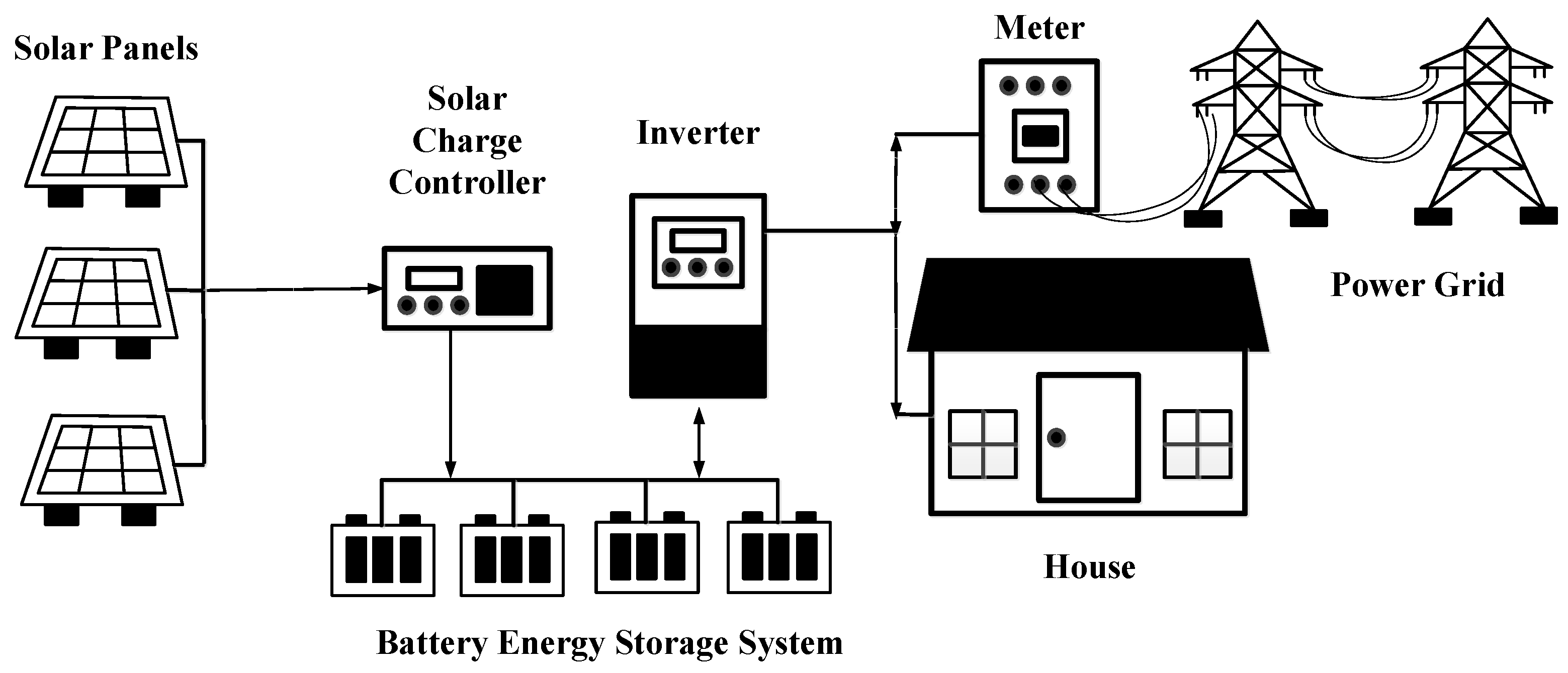
This paper presents the application of a photovoltaic and battery energy storage system to improve voltage drop in an electric supply system and increase efficiency in a distribution system. This distribution system was tested using an IEEE 33-bus radial distribution system with a program in MATLAB (Version R2024b-acdemic use) and analyzed in five cases. The photovoltaic system is shown in Figure 1.

Figure 1.
Photovoltaic system.
2. Photovoltaic Technology
Photovoltaic technology is an invention that is able to convert solar energy directly into an electric current. This effect is called the photovoltaic laboratory. In the year 1954, photovoltaics were invented and used first in the USA, with an efficiency of 6%. Nowadays, photovoltaics have been developed to increase efficiency values. The early objective of photovoltaics is to generate electricity from solar rays in space projects. After general use in space projects, its applications can be expanded to the use of photovoltaics in global industry-grade applications [6].
Voltage drop and power loss enhancement commonly are enhanced by distributed generators, which consist of separated generators, such as water, wind, and solar generators. In this article, the focus is on solar energy, which comprises a type of photovoltaic generator [7].
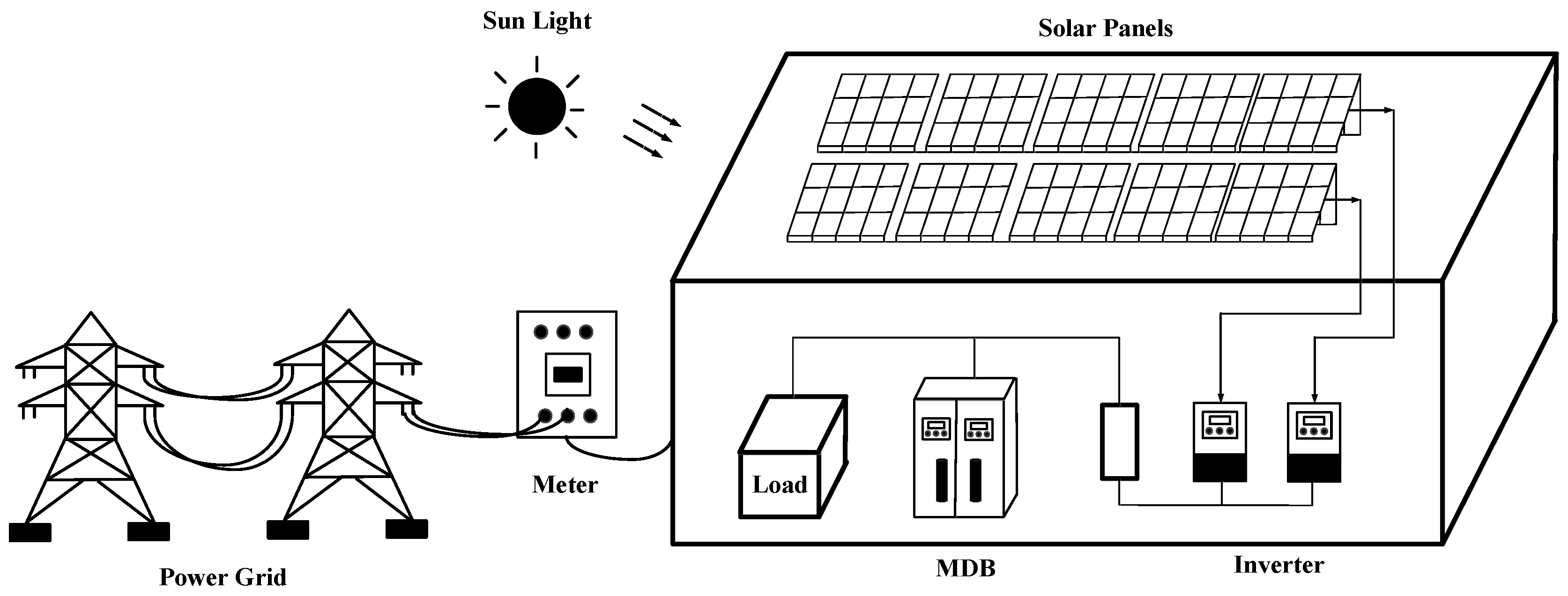
Photovoltaics comprise equipment that converts solar energy to electric energy via solar rays. There are a lot of photovoltaic electric systems connected on a grid in order to enhance overloads or voltages under 0.95 p.u. and even power loss. This system consists of more than two photovoltaic systems that convert solar energy into electric energy in direct current solar power systems, which supply power to a direct current power source, where an inverter converts the direct current power into alternating current power. In recent years, almost all large urban power outages have been caused by the overloading of transmission lines, which are resolved by connecting the distribution system to distributed photovoltaic systems [8]. A photovoltaic system used in a factory is shown in Figure 2.
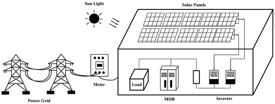
Figure 2.
Photovoltaic system in a factory.
Therefore, a strategy for controlling electric power using solar cells is proposed in this paper to design and meet load demands. This is used within a high-end distribution system, and this strategy is mainly used in downstream power distribution systems and automatic and instantaneous external power supplies, where photovoltaic systems are programmed into a working model that can access the maximum new energy and operate in the grid-connected mode to deliver solar power. This solar cell is used for power users near the end of the transmission line. Distributed solar cell technology is arranged in the distribution system to improve the power loss and voltage drop. With distributed solar cell technology, under technical conditions, the model of the IEEE 33 bus radial distribution system is developed using MATLAB (Version R2024b-acdemic use) [9].
3. Battery Energy Storage System Operation
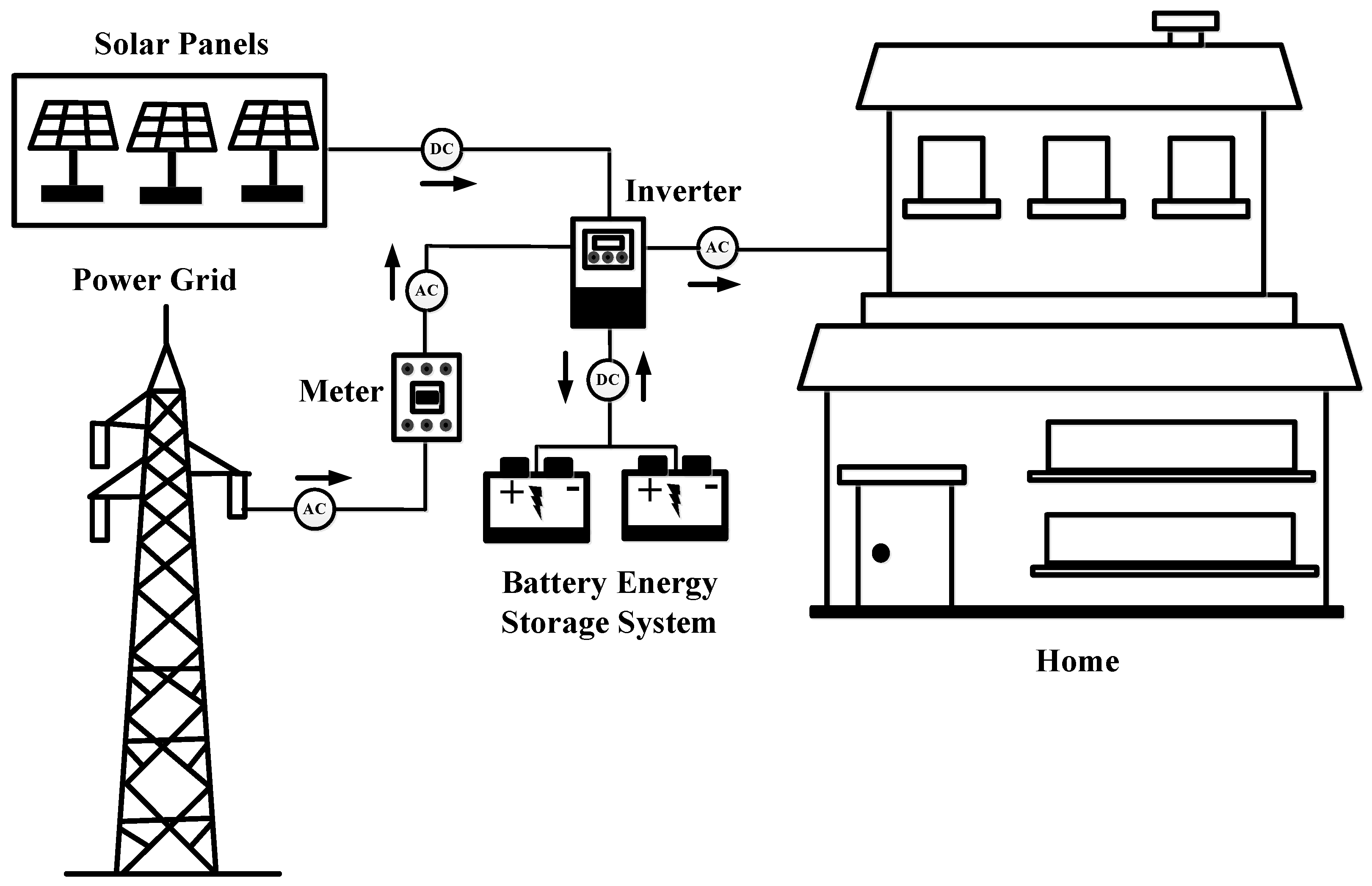
A battery energy storage system is an additional photovoltaic device that stores the oversupply generated electricity when there is more electricity than the needed load. The battery energy storage system stores electric energy and direct currents, which react chemically to transform into preserved electric energy in order to supply the future [10]. The battery energy storage systems used in homes are shown in Figure 3.

Figure 3.
Battery energy storage system in a home.
Battery use for electric energy storage in systems: Solar energy can be stored in high capacities, and it supplies electric currents for a longer period than conventional batteries, which have special thick lead plates in them called deep-cycle batteries. However, this battery is not able to supply high-current electricity. So, it is not good in high-demand electric current applications. During use, the charge should not be lower than 60 percent and should be stored in a cool place with temperatures not exceeding 25 degrees Celsius. The charge must not be too high because it will make the battery very hot and deteriorate faster. Solar cell batteries are used for storing solar energy [11].
In this article, the authors use batteries to store overgenerated energy from solar cells, which is then supplied to transmission lines when photovoltaics are not able to generate electricity. This shows that batteries are able to support any enhanced voltage drops and power loss in IEEE 33 bus radial distribution systems [12].
4. Power Distribution System
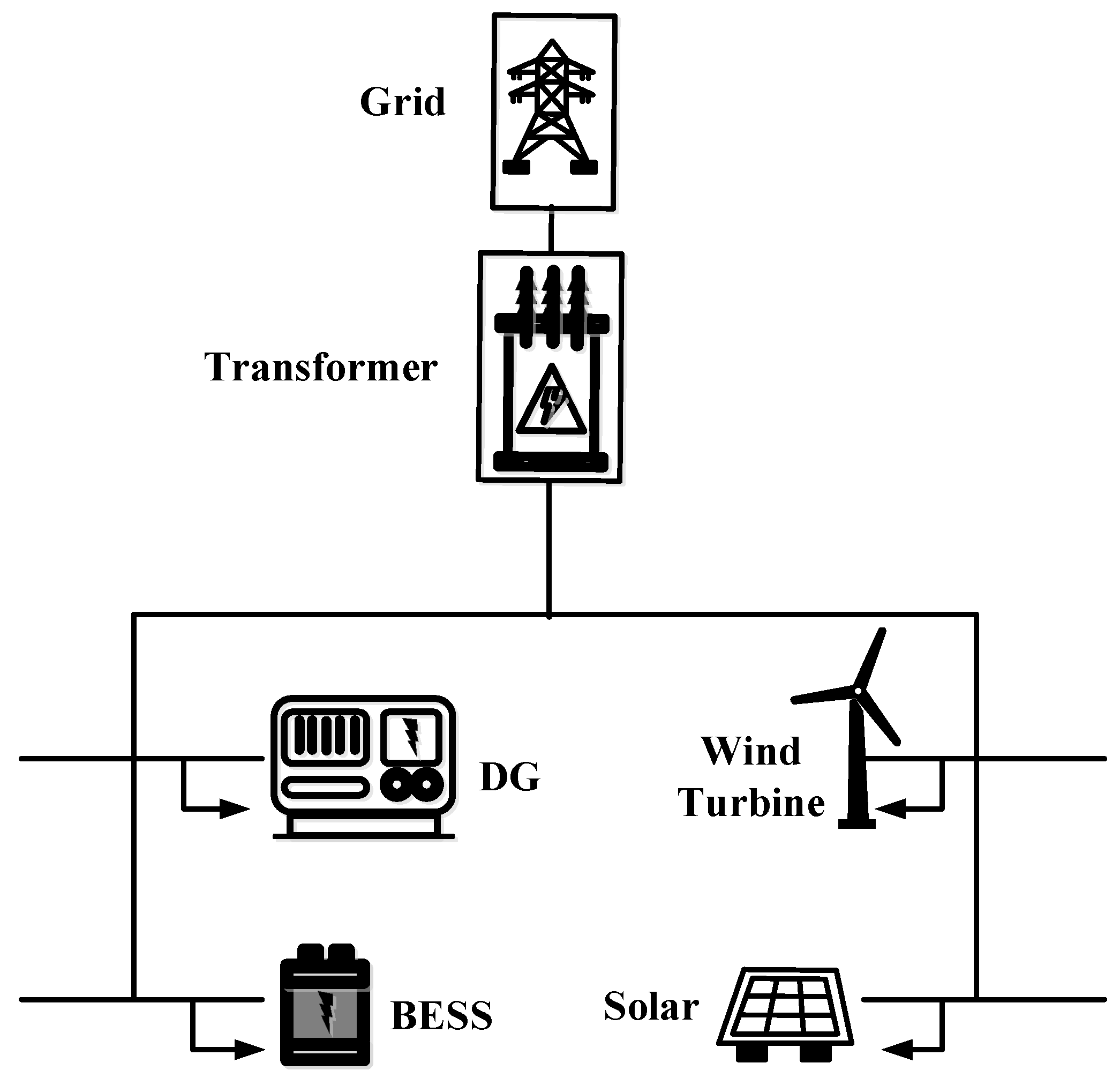
A power distribution system is divided into three systems: one is an electrical generation system, which is a system that transforms other energy into electric energy (for example, photovoltaics from photovoltaic farms convert solar energy into electric energy; dams convert potential energy in water into electric energy; coal electric generators convert heat energy from burning coal into electric energy). Electric energy is supplied to transformers to change the voltage value to high voltages in order to reduce energy loss in electric systems [13]. After this, high-voltage electricity is supplied to switchyards in order to configure electric quality and supplies to the transmission system. The transmission system, which receives electricity from electrical generation systems, then supplies electricity to substations in order to reduce voltages from high voltages to medium voltages. Medium voltages are then supplied to the distribution system. This form of electricity is supplied to transformers, which transform either higher or lower voltages for consumption in houses or factories in one phase or three phases [14]. A power distribution system is shown in Figure 4.
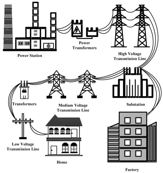
Figure 4.
Power distribution system.
The power distribution system is another important system of homes, office buildings, and various factories. It is also an important part of planning the use of electrical energy in factories or efficient buildings, in which power distribution systems form the basis of creating IEEE 33 bus radial distribution systems [15].
5. IEEE 33 Bus Radial Distribution System
The IEEE 33 bus radial distribution system was developed in 1989, and it is used in study cases about power loss reduction and load balance. This system was tested with respect to smart power and new technology, such as renewable energy generation and demand management mechanisms. In the following years, the IEEE 33 bus radial distribution system for new distributed power supplies was developed, improved, and tested. In order to make the experiment more comprehensive relative to real limitations, a radial case study is proposed. Moreover, the use of case study data in the proposed test system is also increased. The goal is to develop a test system that is similar to a real distribution system with real lines. The original version has a bus voltage of 0.9 to 1.1 for testing, and it has been changed to 0.95 to 1.05, which is the acceptable range in general power distribution systems [16].
At the present time, the electrical energy dataset depends on the geographical location of the installation. In the IEEE 33 bus radial distribution system, the problem of voltage drop and power loss is solved using distributed generators in the installation. Renewable energy or batteries, which are backup power storage systems, can be installed. The electrical energy storage system can be thought of as a power generator or a load depending on the amount of energy, regardless of whether it is the maximum or minimum power supply or a limitation of charging or distributing electricity to the energy storage as specified. This system has losses during charging or distributing electricity depending on the technology [17]. The IEEE 33 bus radial distribution system is shown in Figure 5.
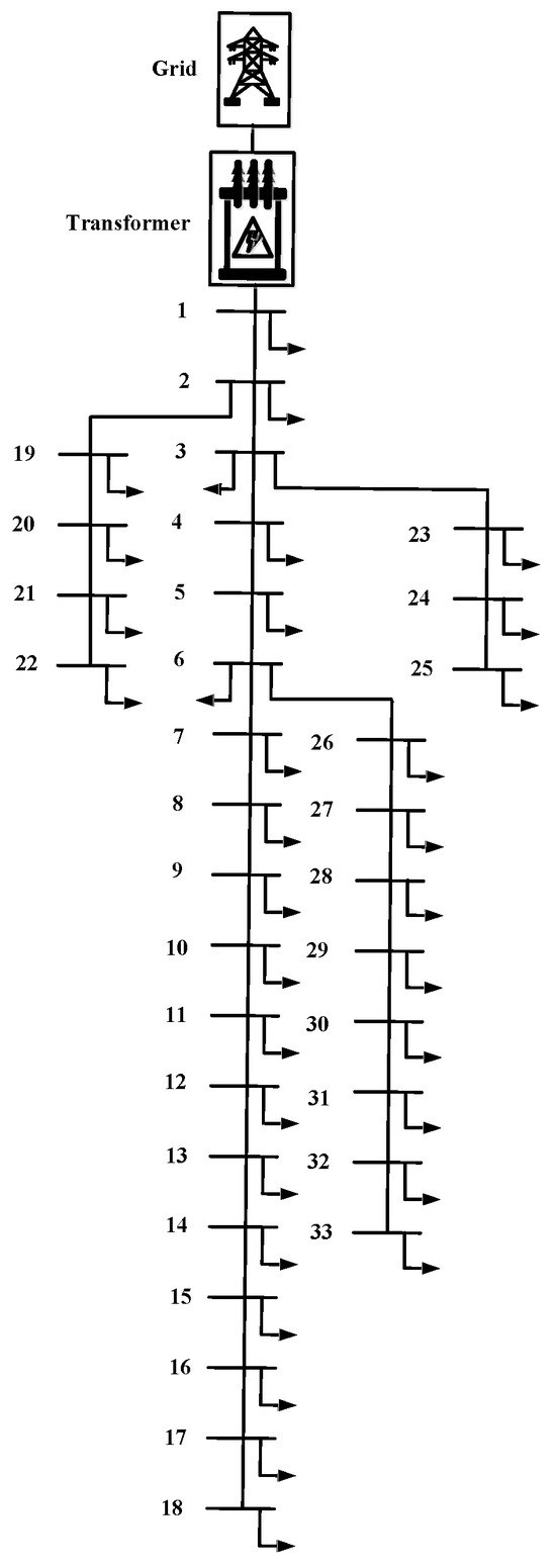
Figure 5.
IEEE 33 bus radial distribution system.
6. Power Loss
In the transmission system, the distribution of electricity to remote locations and locations at the end of transmission lines may cause power losses, voltage drops, or overloads in the power system due to various physical and practical factors, which cause electrical energy to be dissipated in the form of heat and reduced efficiency. These losses occur during the process of transmitting electrical energy over long distances from the power generation site to the consumer. The main causes of power loss are transmission line resistance, transformer losses, and reactive power flow, which are compensated for by distributed generation, which consists of separate generators and sometimes renewable energy, such as hydro power, wind power, solar power, etc. [18].
Simulation power distribution systems with access to distributed generators: The direction of power flow is predominantly towards the network rather than the load side in a conventional distribution system without access to distributed generators. The inflow to the load side is proportional to the distance between the substation and the load side. The current flowing from the substation is the current flowing from the distributed generator power, the distance between the substation and the solar power, and the distance between the solar power and the load side. The generation of distributed generators and loads with a radial distribution system is represented by a bus impedance matrix. When power is lost, the radial distribution system is equivalent to a single node with all connections and loads [19]. The compensation for power loss is shown in Figure 6.

Figure 6.
The compensation for power loss.
7. Power Flow Equation
The real power and reactive power between buses are calculated using Equations (1) and (2) [20].
The power loss in line connections between bus i and bus i + 1 is calculated using Equation (3):
where is the real power and reactive power value at bus i;
is the voltage value at bus i;
is the line resistance value between bus i and i + 1;
is the line reactance value between bus i and i + 1.
8. Flowchart
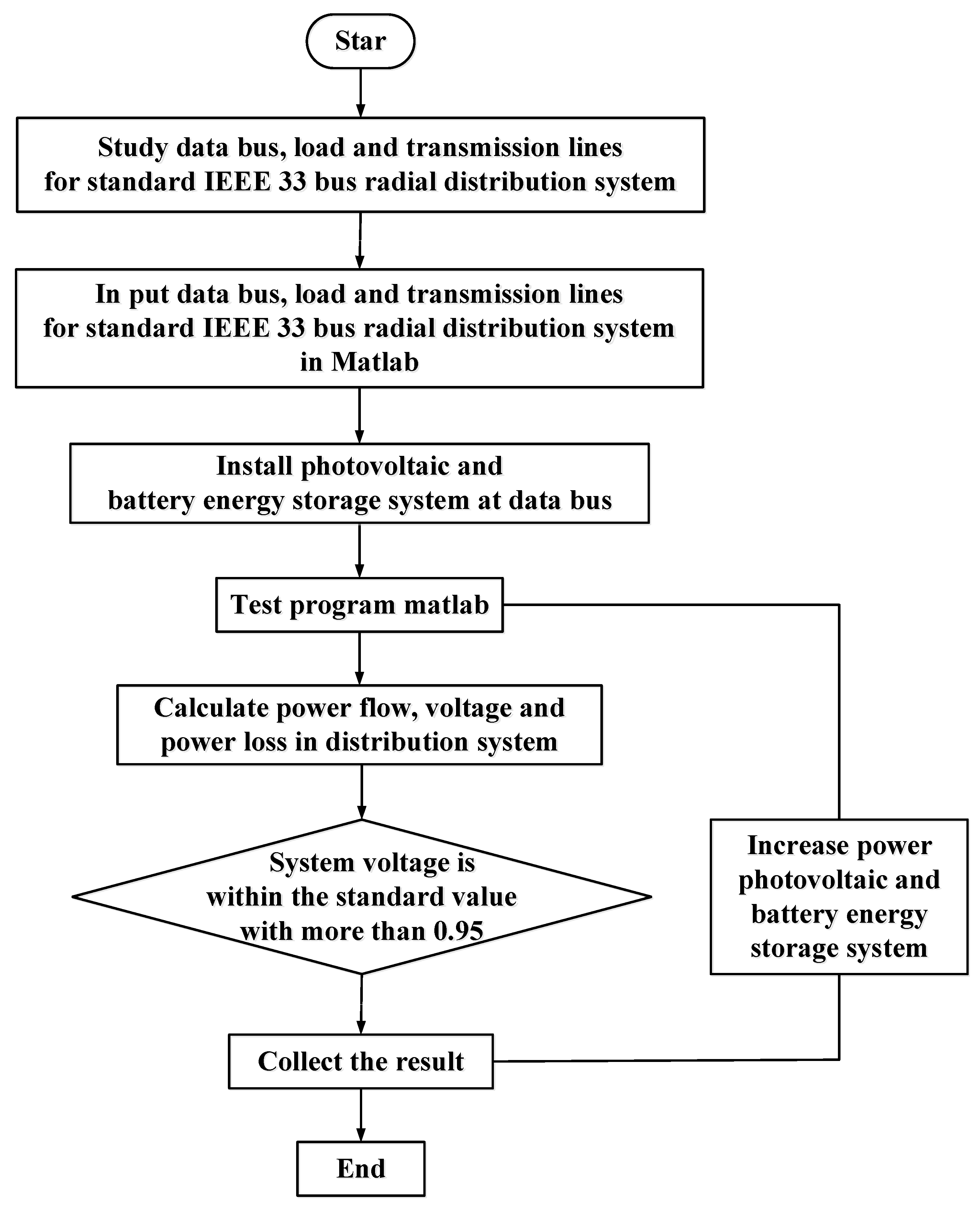
The flowchart shows the procedures for testing in this research paper. The flowchart is shown in Figure 7.
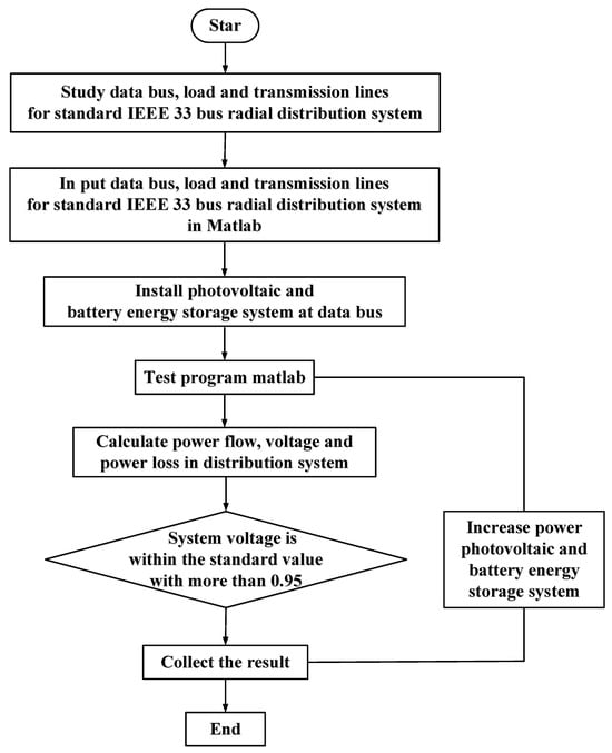
Figure 7.
Flowchart.
In Figure 7, we start by studying data from the IEEE 33 bus radial distribution system. Then, we input the initial data of the IEEE 33 bus radial distribution system into Matlab (Version R2024b-acdemic use). Then, we test the program and study the test results of the IEEE 33 bus radial distribution system by looking at the voltage value and power loss. After this, we noticed that the buses that are mostly at the end of the transmission line of the power distribution system have voltage values that are lower than the standard of 0.95 P.U., and this indicates power loss in the distribution system. Due to this observation, the authors of this article study the voltage drop and power loss. The voltage in the power distribution system can be improved by installing solar cells to supply voltages at the point where the voltage drops, and using a battery helps store excess power produced by the solar cells and supply power when the voltage drops occur. Then, we test the program and study the test results voltage drop and power loss.
9. Case Study
In this study, every bus where a voltage drop occurred required either photovoltaic or battery storage installation. This was carried out to generate voltages of up to or above 0.95 per unit, which is the Thailand standard. There were 5 different condition tests. Due to the metropolitan electricity authority, a bus that exhibited less than 0.95 per unit was considered a site for voltage drops.
Case 1 shows the buses have voltage drops under 0.95 p.u. before the installation of photovoltaic and battery energy storage systems. Case 2 comprises a case from theory, and it installs distributed generators in many buses, which is more efficient than installing a large generator in one bus. So, photovoltaics are installed where voltage drops occurred: bus 16, 18, 31, and 33 with voltage drops of 0.916, 0.913, 0.918, and 0.917, respectively, and photovoltaic sizes of 180, 240, 240, and 400 kW, respectively; the total size of the photovoltaic system is 1060 kW. Case 3 comprises a case in which bus 18, which had the lowest voltage drop of 0.913 p.u. in the IEEE 33 bus system, has a distributed photovoltaic system installed, with the largest size of 1060 kW in one bus. Case 4 comprises a case with photovoltaic systems installed in both buses 18 and 33, which have voltage drops of 0.913 and 0.917 P.U. at photovoltaic sizes of 430 and 630 kW, respectively; the total size of the photovoltaic system is 1060 kW. Case 5 comprises a case in which a more efficient distributed photovoltaic system is installed in one bus, resulting in distributed generator installations of 0.916, 0.913, 0.918, and 0.917 with photovoltaic sizes of 180, 240, 240, and 400 kW, respectively; the total size of the photovoltaic is 1060 kW. In order to increase the efficiency of battery energy storage systems, they are installed on buses 14 and 29, where voltage drops of 0.919 and 0.926, respectively, occur with sizes of 40 kWh; the total size of the battery energy storage system is 80 kWh. These batteries store electric energy from photovoltaic systems. Line data and load in the IEEE 33 bus system during peak load before the installation of photovoltaic and battery energy storage systems as shown in Table 1.

Table 1.
Line data and load in the IEEE 33 bus system during peak load [1].
Case 1: Case 1 is the case before the installation of photovoltaic and battery energy storage systems. Case 1 is shown in Figure 8.
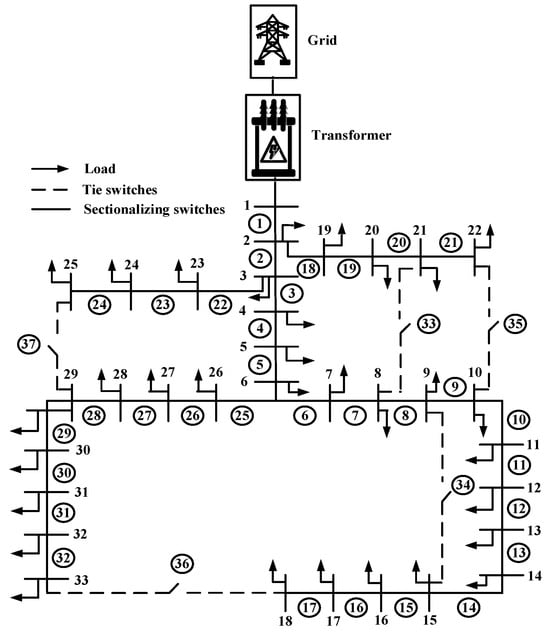
Figure 8.
Case 1 before the installation of photovoltaic and battery energy storage systems.
Case 2: This is the case with photovoltaic systems installed on buses 16, 18, 31, and 33 with photovoltaic sizes of 180, 240, 240, and 400 kW, respectively; the total size of the photovoltaic system is 1060 kW. Case 2 is shown in Figure 9.

Figure 9.
Case 2 with photovoltaic systems installed on buses 16, 18, 31, and 33.
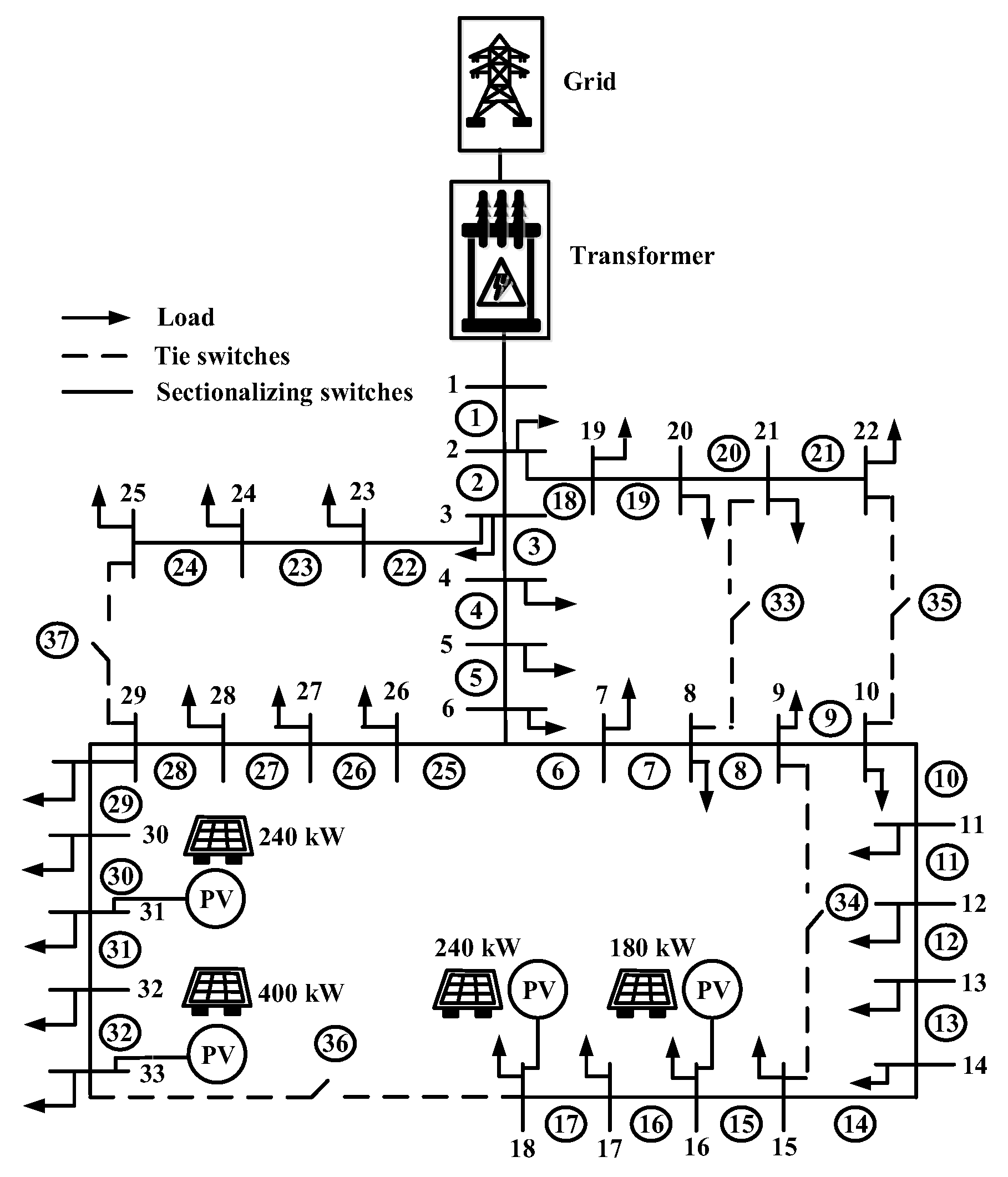
Case 3: This is the case in which a photovoltaic system was installed on bus 18 with a photovoltaic size of 1060 kW; the total size of the photovoltaic system is 1060 kW. Case 3 is shown in Figure 10.

Figure 10.
Case 3 with a photovoltaic system installed on bus 18.
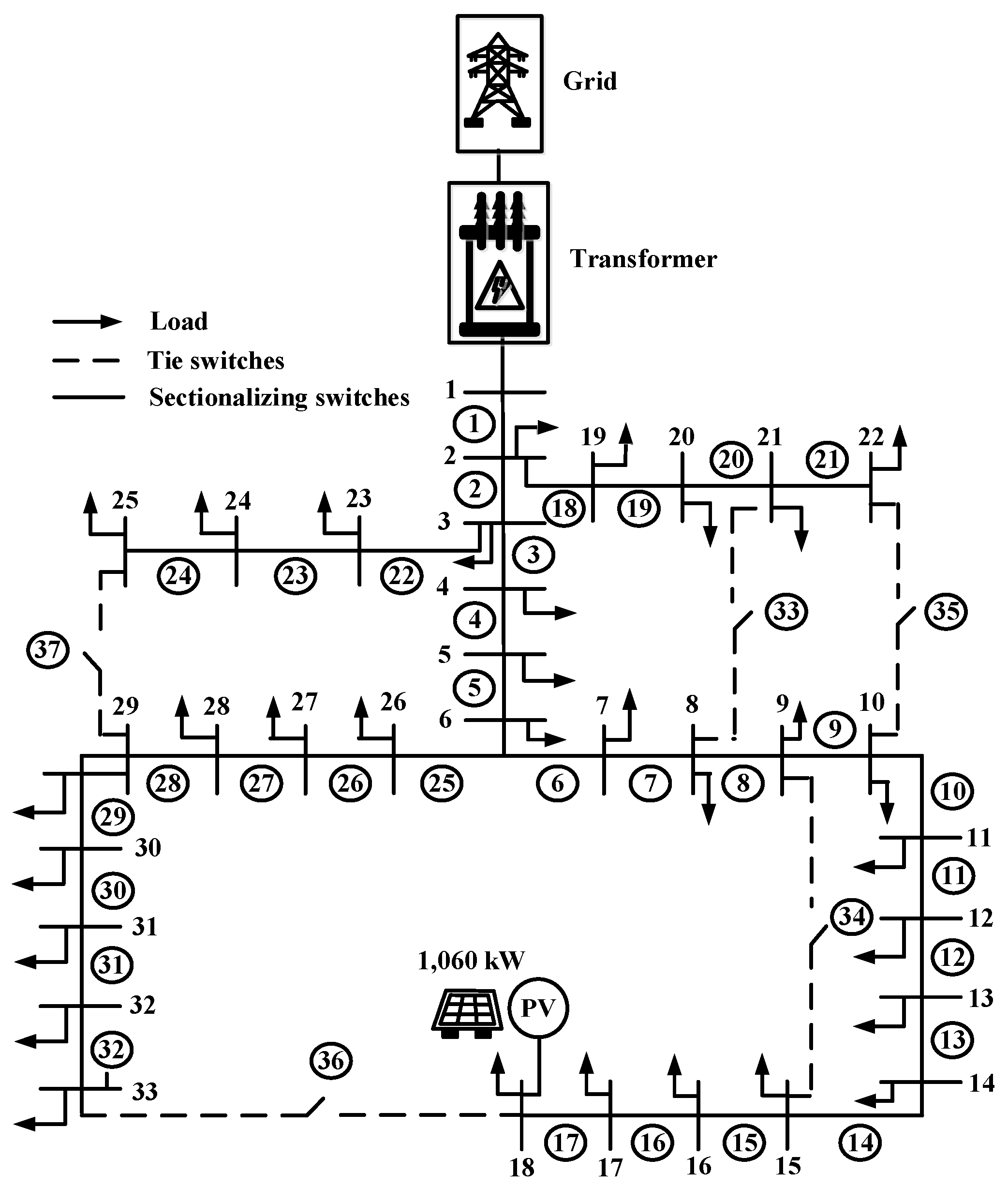
Case 4: This is the case with a photovoltaic system installed on buses 18 and 33 with photovoltaic sizes of 430 and 630 kW, respectively; the total size of the photovoltaic system is 1060 kW. Case 4 is shown in Figure 11.

Figure 11.
Case 4 with a photovoltaic system installed on buses 18 and 33.
Case 5: This is the case with a photovoltaic system installed on buses 16, 18, 31, and 33 with photovoltaic sizes of 180, 240, 240, and 400 kW, respectively; the total size of the photovoltaic system is 1060 kW. Battery energy storage systems are installed on buses 14 and 29 with a size of 40 kWh; the total size of the battery energy storage system is 80 kWh. Case 5 is shown in Figure 12.
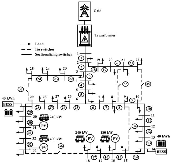
Figure 12.
Case 5 with a photovoltaic system installed on buses 16, 18, 31, and 33 and a battery energy storage system installed on buses 14 and 29.
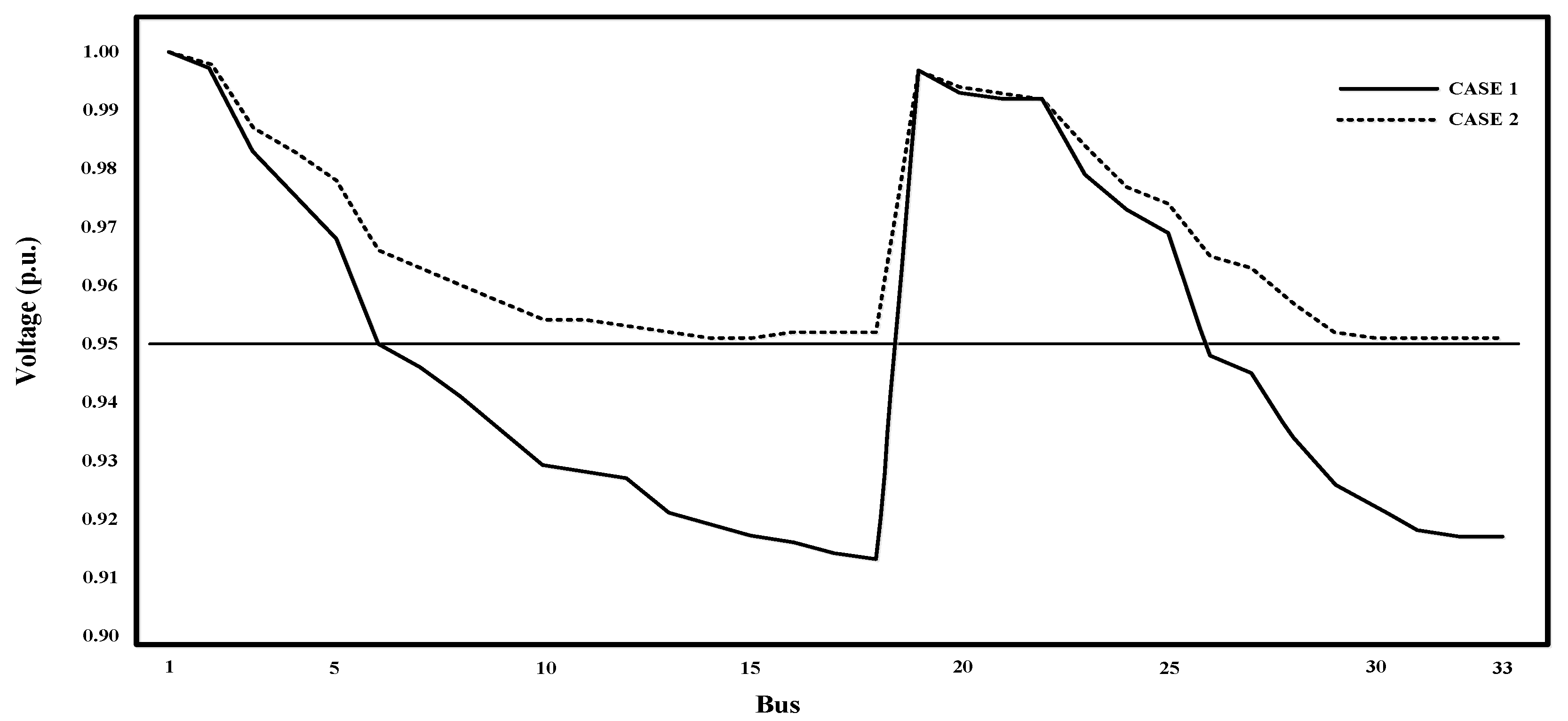
Location and size of photovoltaic and battery energy storage systems case 1, case 2, case 3, case 4, and case 5 as show in Table 2. Resultant voltage (p.u.) case 1, case 2, case 3, case 4, and case 5 as show in Table 3. Figure 13 shows the resultant adjustment voltage drops for case 1 and case 2; this figure shows a comparison between case 1 (the original case with no photovoltaic and battery energy storage systems installed) and case 2 (distributed photovoltaic generator installed on bus 4). Case 1 comprises the case before photovoltaic and battery energy storage systems are installed. The voltage drop numbers below 0.95 per unit bus are 7, 8, 9, 10, 11, 12, 13, 14, 15, 16, 17, 18, 26, 27, 28, 29, 30, 31, 32, and 33. The total number of buses with voltage drops is 20 buses, and the bus with the lowest voltage is bus 18. Case 2 comprises photovoltaic systems installed on buses 16, 18, 31, and 33 with photovoltaic sizes of 180, 240, 240, and 400 kW, respectively; the total size of the photovoltaic system is 1060 kW. None of the voltage drop numbers fell below 0.95 per unit, and the lowest-voltage buses are 14, 15, 30, 31, 32, and 33.
Table 2.
Location and size of photovoltaic and battery energy storage systems.
Table 3.
Resultant voltage (p.u.).
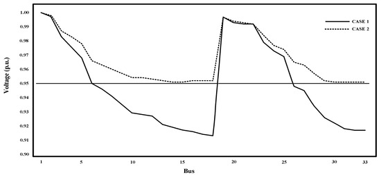
Figure 13.
Resultant adjustment voltage drops case 1 and case 2.
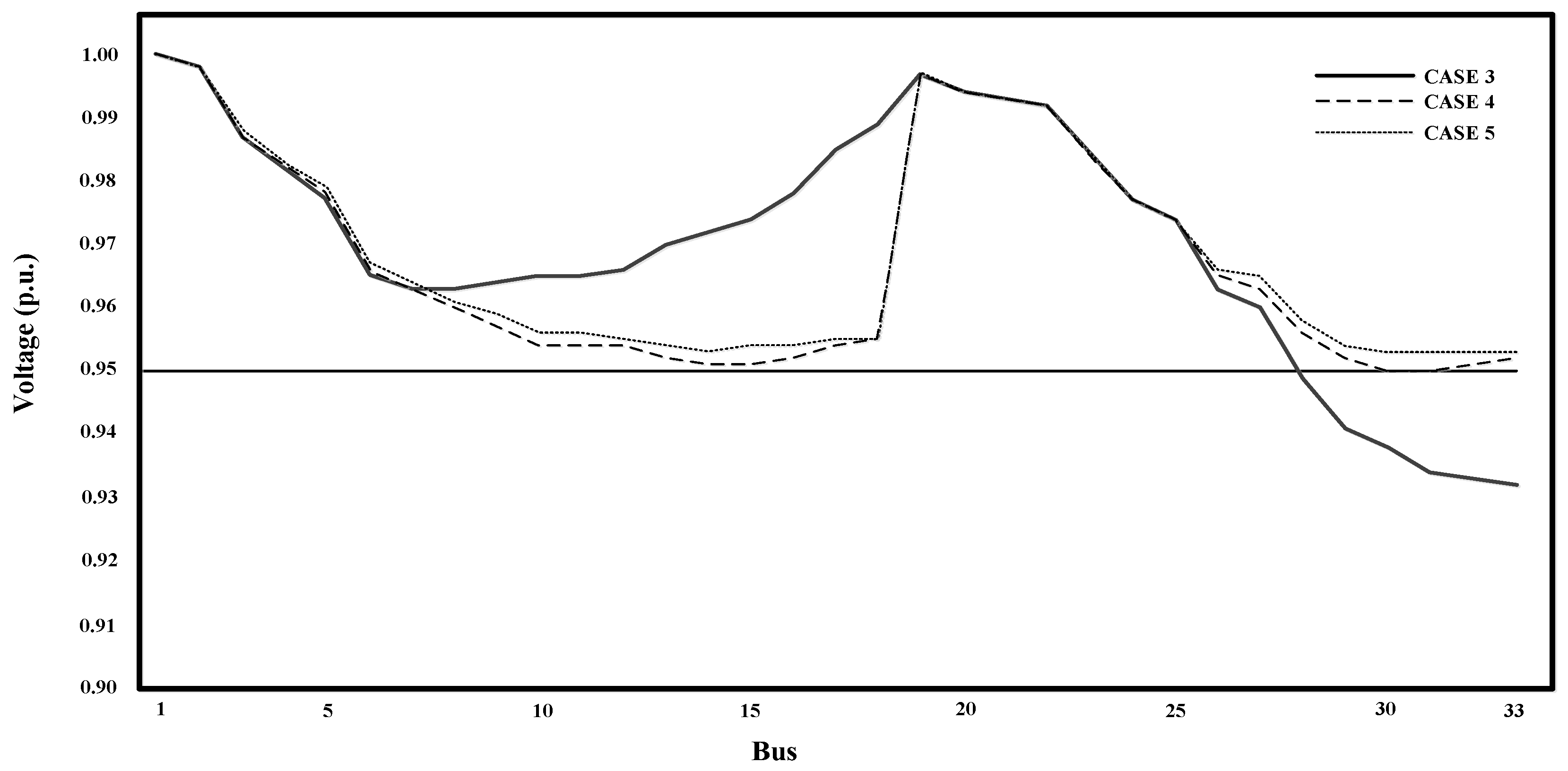
Figure 14 shows the resultant adjustment voltage drops in case 3, case 4, and case 5. This figure shows a comparison between the cases. Case 3 comprises the installation of a distributed photovoltaic generator in only one bus. Case 4 is the case with a distributed photovoltaic generator installed on the two buses that have the most voltage drops, and case 5 comprises the installation of a distributed photovoltaic generator in four buses and the installation of battery energy storage systems in two buses. Case 3 comprises a photovoltaic system installation at bus 18 with a photovoltaic size of 1060 kW; the total photovoltaic size is 1060 kW. The voltage drop numbers below 0.95 per unit bus are 28, 29, 30, 31, 32, and 33. The total number of voltage drop buses is six buses, and the lowest-voltage bus is 33. Case 4 comprises a photovoltaic system installation at buses 18 and 33 with a photovoltaic size of 430 and 630 kW, respectively; the total size of the photovoltaic system is 1060 kW. No voltage drop numbers fell below 0.95 per unit, and the lowest-voltage buses are 30 and 31. Case 5 comprises a photovoltaic system installation at buses 16, 18, 31, and 33 with photovoltaic sizes of 140, 240, 200, and 400 kW, respectively; the total size of the photovoltaic system is 980 kW, and both battery energy storage systems at buses 14 and 29 had a size 40 of kWh; the total size of the battery energy storage system is 80 kWh. None of the voltage drop numbers fell below 0.95 per unit, and the lowest-voltage buses are 30 and 31.
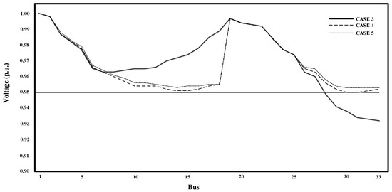
Figure 14.
Resultant adjustment voltage drops in case 3, case 4, and case 5.
Table 4 shows power loss results and the number of buses that experienced voltage drops. Case 1, which is the case without photovoltaic and battery energy storage systems installed, had a total power loss of 202.45 kW. Case 2, which had photovoltaic systems installed on buses 16, 18, 31, and 33 with photovoltaic sizes of 180, 240, 240, and 400 kW, respectively, and a total photovoltaic size of 1060 kW, had a total power loss of 108.64 kW. Case 3, which comprises a photovoltaic system installed on bus 18 with a photovoltaic size of 1060 kW and a total photovoltaic size of 1060 kW, had a total power loss of 147.17 kW. Case 4, which is the case with a photovoltaic system installed on buses 18 and 33 with a photovoltaic size of 430 and 630 kW, respectively, and a total photovoltaic size of 1060 kW, had a total power loss of 110.65 kW. Case 5 had a total power loss of 104.55 kW; this is the case with a photovoltaic system installed on buses 16, 18, 31, and 33 with a photovoltaic size of 140, 240, 200, and 400 kW, respectively, and a total size of photovoltaic 980 kW, and battery energy storage systems were installed on both buses 14 and 29 with a size of 40 kWh. The total size of the battery energy storage system is 80 kWh.
Table 4.
The resultant power loss and the number of buses that had voltage drops.
10. Conclusions
Battery storage systems were applied to increase photovoltaic system efficiency in distribution systems. This paper presents the utilization of distributed photovoltaic generation using photovoltaic systems and batteries to support voltage drops and power loss, and five cases were examined. Case 1 comprises the case before the installation of photovoltaic and battery energy storage systems. The total number of voltage drop buses is 20 buses, and the power loss is 202.45 kW. Case 2 comprised the installation of a distributed photovoltaic generator in four buses, buses 16, 18, 31, and 33, with photovoltaic sizes of 180, 240, 240, and 400 kW. None of the voltage drop numbers fell below 0.95 per unit, and the power loss was 108.64 kW, which was even more reduced than the power loss in case 1 (93.81 kW). Case 3 is the case in which a distributed photovoltaic generator was installed on only one bus. Case 3 comprised the case with a photovoltaic system installed on bus 18 with a photovoltaic size of 1060 kW. The total number of voltage drop buses is six buses, and the power loss is 147.17 kW, which is even more reduced than the power loss in case 1 (55.28 kW). Case 4 is the case in which a distributed photovoltaic generator was installed on two buses with the most voltage drops. Case 4 is the case in which a photovoltaic system was installed on buses 18 and 33 with photovoltaic sizes of 430 and 630 kW. None of the voltage drop numbers fell below 0.95 per unit, and the power loss was 110.65 kW, which was even more reduced than the power loss in case 1 (91.80 kW). Case 5 comprised a distributed photovoltaic generator installed in four buses, and battery energy storage systems were installed in two buses. Case 5 comprised a photovoltaic system installed in buses 16, 18, 31, and 33 with photovoltaic sizes of 140, 240, 200, and 400 kW, and battery energy storage systems were installed in buses 14 and 29 with a size of 40 kWh. None of the voltage drop numbers fell below 0.95 per unit, and the power loss was 104.55 kW, which was even more reduced than the power loss in case 1 (97.90 kW). So, case 2 is the best distributed photovoltaic generation installation without a battery system. None of the voltage drop numbers fell below 0.95 per unit, and the power loss was 108.64 kW, but case 5 is better than case 2 because case 5’s total size is larger than case 2, and more battery energy storage systems are installed as auxiliary systems. No voltage drop numbers fell below 0.95 per unit, and the power loss was 104.55 kW.
In this article, studies about voltage drop solutions in an IEEE 33 bus radial distribution system with respect to photovoltaic and battery systems were divided into five cases. In all five cases, the installation of different photovoltaic systems on different buses was carried out. However, the total size of the solar cell in all five cases was equal.
In obvious voltage drop solutions, case 2, case 4, and case 5 were able to solve voltage drop situations in every bus with respect to the voltage standard, which is higher than or equal to 0.95. However, when compared in terms of the power loss in case 2 and case 5, which both have equal sizes, Case 5, with a battery installed additionally, exhibits higher voltages and a decrease in power loss compared to case 2.
Author Contributions
Conceptualization, N.C. and N.R.; formal analysis, N.R. and N.C.; original draft preparation, N.R. and N.C.; writing—review and editing, N.C. and N.R. All authors have read and agreed to the published version of the manuscript.
Funding
This research received no external funding.
Data Availability Statement
The study’s original contributions are included within the article, and any further inquiries can be directed to the corresponding authors.
Acknowledgments
The authors would like to express their sincere thanks to the Rajamangala University of Technology Phra Nakhon (RMUTP), Thailand, for their support.
Conflicts of Interest
The authors declare no conflicts of interest.
References
- Dewantara, M.; Putranto, L.M.; Irnawan, R.; Sarjiya. Minimization of power losses through optimal placement and sizing from solar power and battery energy storage system in distribution system. In Proceedings of the 2020 3rd International Seminar on Research of Information Technology and Intelligent Systems (ISRITI), Yogyakarta, Indonesia, 10–11 December 2020; pp. 400–405. [Google Scholar]
- Wannakarn, P.; Kesphrom, N.; Nedphokaew, S.; Rugthaicharoencheep, N. Power distribution system improvement considering damage cost due to voltage sags. In Proceedings of the 2023 IEEE PES 15th Asia-Pacific Power and Energy Engineering Conference (APPEEC), Chiang Mai, Thailand, 6–9 December 2023. [Google Scholar]
- Da Silva, D.J.; Belati, E.A.; López-Lezama, J.M. Optimal Allocation and Operation of Energy Storage Systems with Photovoltaic Power Generation. In Proceedings of the 2023 15th IEEE International Conference on Industry Applications (INDUSCON), São Bernardo do Campo, Brazil, 22–24 November 2023. [Google Scholar]
- Rugthaicharoencheep, N.; Ruangsap, N.; Nedphokaew, S. Shortening the payback period of greenhouse gas reduction benefits from photovoltaic rooftop systems. Energies 2024, 17, 6159. [Google Scholar] [CrossRef]
- Yang, J.; Zhang, L.; Xu, J.; Yin, T.; Lin, L. The energy management scheme for photovoltaic/battery power conversion system. In Proceedings of the 2024 CPSS & IEEE International Symposium on Energy Storage and Conversion (ISESC), Xi’an, China, 8–11 November 2024; pp. 578–584. [Google Scholar]
- Wan, C.; Zhao, J.; Song, Y.; Xu, Z.; Lin, J.; Hu, Z. Photovoltaic and solar power forecasting for smart grid energy management. CSEE J. Power Energy Syst. 2015, 1, 38–46. [Google Scholar] [CrossRef]
- Papon, N.; Nattachote, R. Optimization technique for voltage sag with integration of photovoltaic energy distributed generation. GMSARN Int. J. 2024, 18, 414–420. [Google Scholar]
- Upasani, M.; Patil, S. Grid connected solar photovoltaic system with battery storage for energy management. In Proceedings of the 2018 2nd International Conference on Inventive Systems and Control (ICISC), Coimbatore, India, 19–20 January 2018; pp. 438–443. [Google Scholar]
- Zhao, H.; Zhang, J.; Gao, B.; Cui, Z. Optimization and Simulation of Photovoltaic Microgrid Composite Energy Storage System Network Format. In Proceedings of the 2023 3rd International Conference on Energy Engineering and Power Systems (EEPS), Dali, China, 28–30 July 2023. [Google Scholar]
- Shavolkin, O.; Shvedchykova, I.; Kravchenko, O. Three-phase grid inverter for combined electric power system with a photovoltaic solar battery. In Proceedings of the 2019 IEEE International Conference on Modern Electrical and Energy Systems (MEES), Kremenchuk, Ukraine, 23–25 September 2019; pp. 318–321. [Google Scholar]
- Wang, Y.C.; Ho, T.; Wang, J.Y. Battery charger for a photovoltaic power source. In Proceedings of the 2013 IEEE International Symposium on Consumer Electronics (ISCE), Hsinchu, Taiwan, 3–6 June 2013; pp. 17–18. [Google Scholar]
- Teja, S.C.; Yemula, P.K. Energy management of grid connected rooftop solar system with battery storage. In Proceedings of the 2016 IEEE Innovative Smart Grid Technologies—Asia (ISGT-Asia), Melbourne, Australia, 28 November–1 December 2016; pp. 438–443. [Google Scholar]
- Dolatabadi, S.H.; Ghorbanian, M.; Siano, P.; Hatziargyriou, N.D. An enhanced IEEE 33 bus benchmark test system for distribution system studies. IEEE Trans. Power Syst. 2021, 36, 2565–2572. [Google Scholar] [CrossRef]
- Laowanitwattana, J.; Uatrongjit, S. Probabilistic power flow analysis based on low rank approximation and principle component analysis. In Proceedings of the 2020 International Conference on Power, Energy and Innovations (ICPEI), Chiangmai, Thailand, 14–16 October 2020; pp. 185–188. [Google Scholar]
- Saonerkar, A.K.; Bagde, B.Y. Optimized DG placement in radial distribution system with reconfiguration and capacitor placement using genetic algorithm. In Proceedings of the 2014 IEEE International Conference on Advanced Communications, Control and Computing Technologies, Ramanathapuram, India, 8–10 May 2014; pp. 1077–1083. [Google Scholar]
- Skok, S.; Havaš, L.; Radosevic, V.; Cvitanovic, M. Impact of electromobility to the power distribution system. In Proceedings of the 2020 IEEE PES/IAS PowerAfrica, Nairobi, Kenya, 25–28 August 2020. [Google Scholar]
- Coria, G.E.; Penizzotto, F.; Romero, A. Probabilistic analysis of impacts on distribution networks due to the connection of diverse models of plug-in electric vehicles. IEEE Lat. Am. Trans. 2020, 18, 2063–2072. [Google Scholar] [CrossRef]
- Puvi, V.; Lehtonen, M. Stochastic Assessment of voltage unbalance mitigation by battery system in case of single-phase solar generation. In Proceedings of the 2018 International Symposium on Power Electronics, Electrical Drives, Automation and Motion (SPEEDAM), Amalfi, Italy, 20–22 June 2018; pp. 171–176. [Google Scholar]
- Nair, V.; Gulur, S.; Chattopadhyay, R.; Bhattacharya, S. Integrating photovoltaics and battery energy storage to grid using triple active bridge and voltage source converters. In Proceedings of the IECON 2020 The 46th Annual Conference of the IEEE Industrial Electronics Society, Singapore, 18–21 October 2020; pp. 3691–3696. [Google Scholar]
- Tamilselvan, V.; Jayabarathi, T. Multi objective Flower Pollination Algorithm for solving capacitor placement in radial distribution system using data structure load flow analysis. Arch. Electr. Eng. J. 2016, 65, 203–220. [Google Scholar] [CrossRef]


Disclaimer/Publisher’s Note: The statements, opinions and data contained in all publications are solely those of the individual author(s) and contributor(s) and not of MDPI and/or the editor(s). MDPI and/or the editor(s) disclaim responsibility for any injury to people or property resulting from any ideas, methods, instructions or products referred to in the content. |
© 2025 by the authors. Licensee MDPI, Basel, Switzerland. This article is an open access article distributed under the terms and conditions of the Creative Commons Attribution (CC BY) license (https://creativecommons.org/licenses/by/4.0/).