Abstract
It is well established that solar cells convert solar energy into electrical energy, thereby contributing to environmental sustainability by reducing dependence on fossil fuels. In the present study, thin films composed of different materials were employed with the aim of mitigating efficiency losses in polycrystalline solar cells, which operate at a specific output voltage of 0.5 V. To evaluate the performance of these films, solar irradiation tests were conducted in Ciudad Obregón, Sonora, Mexico, during periods that accounted for both seasonal and diurnal variations in solar irradiance. The experiments were carried out during peak solar hours, a time frame that represents the conditions of highest thermal stress and irradiance intensity and is therefore relevant for analyzing heat-related efficiency losses. The thin films investigated included silver nanoparticles, copper sulfide, potassium permanganate, zinc sulfide, and lead sulfide. An improvement of 0.5% in open circuit voltage gain was achieved, corresponding to a temperature difference of 13.5 °C between the hottest and coolest cells. Notably, the cells that exhibited efficiency enhancement were those incorporating silver nanoparticles and potassium permanganate, with varying deposition times in the chemical bath. Among these, the latter demonstrated superior performance (KMnO4 performed best). So, the objective of this experimental work was to assess the effect of various thin film coatings on the performance of polycrystalline silicon solar cells under natural sunlight.
1. Introduction
Solar cells have become very important in recent years due to their ability to harness solar energy and convert it into electrical energy. Therefore, improving their efficiency is of utmost importance in order to contribute to environmental sustainability [1,2,3]. It is also well established that the performance of photovoltaic solar panels is strongly influenced by their operating temperature. In this regard, it has been reported that beyond the optimal operating temperature of 25 °C, efficiency decreases by approximately to for every additional degree Celsius [4]. This loss not only compromises energy conversion but also accelerates system aging, as most solar panels tend to degrade at a rate of between and per year, regardless of other equipment related issues.
Current silicon-based technologies represent more than of the global photovoltaic market and exhibit an average efficiency ranging from to [5]. A detailed analysis of energy losses in silicon modules found that under real-world conditions, only of incident solar energy is converted into electricity, while is lost due to reflection, is lost through transmission, is lost through convection, and is lost through thermal radiation. Therefore, silicon-based solar cells have limited efficiency due to their restricted spectral absorption range. A significant portion of the incident radiation is not converted into electricity but instead becomes heat, increasing the cell’s operating temperature and reducing its performance. In particular, absorption occurs across the 0.4 μm-to-1.1 μm spectral range in the Si layer, where part of this energy is converted into electricity and the remainder is converted to heat. The irradiance transmitted through the silicon cell, predominantly in the infrared band ( > 1.1 μm), does not contribute to electrical generation but adds to the thermal load of the system [6]. Because of this behavior, the management of the unused spectrum to reduce thermal losses and enhance overall cell efficiency becomes important when designing solar cells.
Another promising approach to improving the efficiency of silicon-based solar cells involves the use of metallic nanoparticles as optical coatings. In particular, silver nanoparticles can enhance light absorption, boosting the interaction of the cell with incident radiation. However, their application must be carefully optimized: excessive deposition can block incoming light and reduce the active surface area of the cell, ultimately reducing the performance. Therefore, managing spectral interaction through optimized nanoparticle coatings allows improved light transmission, minimized thermal load, and improved energy conversion efficiency [7].
Various strategies have been proposed to dissipate heat in solar cells, including the use of protective ceramic coatings (e.g., sol–gel – ) [8], Bragg reflectors [9,10], semitransparent solar cells with perovskite nanopillar structures [11,12,13] and nanostructures designed to improve light trapping in thin-film solar cells [14,15,16]. Among these, thin-film solar cells are considered a promising alternative due to their cost effectiveness and lower material consumption, along with a growing trend toward higher efficiency. These cells require significantly less semiconductor material compared to crystalline silicon cells, which significantly reduces production costs and the demand for scarce resources [17,18]. Moreover, certain configurations of thin-film technologies enable the fabrication of semitransparent modules suitable for use in solar windows, which generate electricity without completely blocking incoming light. These cells also tend to maintain stable efficiency under high temperatures and diffuse (cloudy) light conditions. Specifically, chalcogenide-based solar cells are increasingly in competition with silicon-based cells depending on the indoor or outdoor environment [19] and in some cases even outperform silicon solar cells [20]. Ye Jiang et al. [21] introduced a novel technique to enhance the efficiency of multicrystalline silicon (mc-Si) solar cells by employing isotropic etching with a mixture of HF and potassium permanganate (KMnO4), contrasting with traditional methods that use hydrogen peroxide (H2O2). Furthermore, it is already known that incorporating silver nanoparticles improves light scattering on the surface of a material, which in turn reduces extreme temperatures in silicon solar cells and thereby increases their efficiency. For these reasons, the present work focuses on applying thin films of specific materials to commercial polycrystalline silicon solar cells and comparing their electrical efficiency to that of untreated cells.
In this study, we hypothesize that the application of thin films deposited via a chemical bath can reduce the operating temperature of polycrystalline silicon solar cells and, consequently, improve their voltage response under natural solar irradiation. Specifically, the objective is to compare the thermal and electrical behavior of cells coated with KMnO4, Ag nanoparticles, and ZnS nanoparticles in order to identify which of these materials provides the greatest improvement in voltage and the greatest reduction in temperature under real outdoor conditions. In addition, the study introduces a systematic variation in the chemical bath deposition (CBD) time (30 min, 1 h, and 1.5 h), reporting the condition that yielded the most favorable voltage response. This dual-approach comparison of different materials and immersion times allows for a more reliable assessment of the relative effectiveness of these coatings in mitigating thermal effects and improving the voltage performance of polycrystalline silicon solar cells.
2. Materials and Methods
Regarding the methodology, commercial solar cells rated at 0.5 V were used with dimensions of 39 mm × 19 mm and a thickness of 1 mm. Each cell was coated using CBD with one of the following materials, see Appendix A for formulation: potassium permanganate (KMnO4), silver nanoparticles (Ag), zinc sulfide (ZnS), copper sulfide (CuS), or lead sulfide (PbS). Following the coating process, X-ray Photoelectron Spectroscopy (XPS) was conducted to verify the chemical composition of the deposited films. The XPS results confirmed the presence of the intended materials (KMnO4, Ag, ZnS, CuS, PbS) and the absence of contamination or unintended compounds, validating the chemical integrity of the thin films. In preparing the formulations described in Appendix A, physicochemical considerations widely supported in the literature on the formation of thin films from aqueous solutions were incorporated. These criteria include control of nanoparticle agglomeration, chemical stability of precursors, proper pH adjustment, and the effect of dilution on the uniformity, continuity, and surface quality of coatings. These aspects coincide with those reported by Pylnev et al. [22], who emphasize that controlled dispersion, progressive reduction of concentration, and chemical management prior to the deposition process are decisive factors in obtaining homogeneous layers using solution coating techniques. Although their study uses sequential spin-coating, the general principles described are applicable to various solution-based methodologies, including the CBD technique used in this work, and were considered when formulating the deposition baths used in the present investigation.
To confirm the optical properties of the coatings, spectral characterization analyses were conducted using a UV-Vis spectrophotometer and a full spectrum light source. These tests were performed to identify which wavelengths were more effectively transmitted or blocked by each material. The coated cells were exposed to natural sunlight between 10:00 a.m. and 3:00 p.m., the peak irradiance period in northern Mexico during summer. For each material, experiments were conducted in duplicate, and the averaged values were used for analysis to ensure reliability. Electrical performance parameters, were recorded using a a Keysight 34970A data logger (manufactured by Keysight Technologies, Inc., headquartered in Santa Rosa, CA, USA). with real-time acquisition capability. K type contact thermocouples were placed on each cell to measure surface temperature throughout the experiments. In addition, a meteorological station Kestrel 5500 Weather Meter (produced by the Nielsen-Kellerman Company, headquartered in Boothwyn, PA, USA), was used to monitor environmental variables such as air temperature, relative humidity and wind speed, also solar irradiance was mesured with a Kipp & Zonen CMP3 pyranometer (produced by Kipp & Zonen (OTT HydroMet), headquartered in Delft, The Netherlands) (see Figure 1).
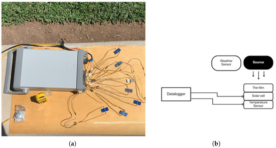
Figure 1.
Measurements under clear sky conditions for the comparison of commercial solar cell open circuit voltage drop. (a) Photograph of the system, (b) Schematic of the system.
The cells coated with PbS, ZnS, and CuS exhibited reduced efficiency under all test conditions and time intervals, during which the approx resultant voltage was 0.2 to 0.3. That is, these treatments decreased the overall performance of the silicon cells. Consequently, while these results are acknowledged, they are not the focus of this work and will not be reported in detail due to the lack of observed improvements. In contrast, the use of Ag nanoparticles and KMnO4 yielded promising results. Therefore, a modified CBD process was applied specifically to these materials. The solar cells were immersed in the chemical bath 1.5 h to compare their efficiency against that of untreated commercial cells. As shown in Figure 2, the cells applied with the CBD process exhibited increased average voltage efficiency compared to the untreated commercial cell during that time. For instance, the cells coated with silver nanoparticles proved to be more efficient than the uncoated cell, which is expected at high temperatures due to the enhanced diffusion of solar radiation by the nanoparticles [23]. This effect results in reduced surface heating of the cell. Surprisingly, the cells coated with thin films of potassium permanganate also outperformed the untreated cell. This result has been supported by previous studies [21], suggesting that potassium permanganate may contribute to heat dissipation. However, this work highlights that the difference in the immersion time during the chemical bath used to fabricate the potassium permanganate thin film with silver nanoparticles is a key factor. In contrast to Ye Jiang et al. [21], who designed nanoscale grooves using the permanganate chemical etching method and obtained efficiencies of in power, in this case the chemical bath deposition method was used, yielding positive results in voltage gains against temperature. In contrast, the solar cell coated with ZnS displayed comparable or even lower efficiency than the untreated cell at certain times of the day. By integrating the areas under the curves in Figure 2, the efficiency of a polycrystalline solar cell with the specifications used in this work is approximately . When adding the voltage efficiency achieved with the permanganate coating, which is .
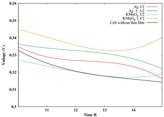
Figure 2.
Average open circuit voltage of the solar cells at different times of the day. Ag ½: cell coated with silver for half an hour; Ag 1½: cell coated with silver nanoparticles for one and a half hours; KMnO4 ½: cell treated with potassium permanganate for half an hour; KMnO4 1½: cell treated with potassium permanganate for one and a half hours; S. Cell: a polycrystalline Si cell without CBD.
Table 1 presents the statistical parameters derived from the time interval with the greatest signal stability, corresponding to the period of maximum solar radiation between 12:00 and 13:00, for each of the experimental conditions shown in Figure 2. The average, maximum, minimum, standard deviation, and coefficient of variation values are reported, which allow both the characteristic voltage level and the associated variability in this representative section to be quantified. All reported columns correspond to voltage values expressed in volts. Overall, the results show that the Ag and KMnO4 coatings maintain higher average values and lower relative dispersion compared to the uncoated cell, reflecting more stable behavior during the period of greatest thermal and radiative stress.

Table 1.
Statistical parameters of voltage during the interval of maximum irradiation. C. w. t. f. means cell without thin film.
Table 2 summarizes the statistical parameters corresponding to the maximum solar radiation interval (12:00 to 13:00) for the thermal and environmental variables associated with Figure 3a,b. The average, maximum, minimum, standard deviation, and coefficient of variation values are presented for the temperatures of the uncoated cells, with Ag and with KMnO4 with half-hour and hour-and-a-half baths, as well as for irradiance, ambient temperature, and relative humidity. All temperature values are expressed in degrees Celsius (°C), the irradiance measurements are reported in watts per square meter (W/m2), and the relative humidity values are expressed as percentages . These indicators allow for a comparative quantification of the thermal behavior of each configuration under conditions of maximum energy demand, showing that coated cells, particularly those treated with KMnO4, reach significantly lower temperatures than the reference cell, while maintaining environmental stability during the analyzed period.
Table 2.
Statistical parameters for temperature and environmental indicators during the period of maximum irradiation. Meaning of abbreviations; T. c. w. t. f. temperture cell without thin film, S. D. Standard Deviation, C. V. Coefficient of variation, Irr. irradiation, R. H. Relative Humidity.
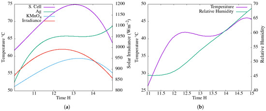
Figure 3.
(a) Average temperature of thin film coated solar cells and cells without thin films versus time of day. Solar irradiance for the day is plotted on the right-hand y axis and (b) Weather data measurements.
Figure 3a shows the cell temperature on the left y axis plotted against the time of day on the x axis and Figure 3b shows the weather measurements, including temperature and relative humidity, at the same site where the solar cell experiments were performed. It can be observed that the solar cell treated with a potassium permanganate bath exhibits the lowest temperature. This efficiency was achieved, corresponding to a temperature difference of 13.5 °C between the hottest and coldest cells. The half-hour permanganate treatment and the silver treatment (also with a half-hour bath) result in lower temperatures compared to the untreated (pristine) cell. The incident solar irradiance, indicated by red circles, is plotted on the right y axis. These results demonstrate that the incorporation of silver nanoparticles and the potassium permanganate treatment enhanced the solar cell’s ability to dissipate heat.
In Figure 4 Voc vs temperature plot of the three solar cells is reported. It is observed that lower operating temperatures result in higher voltage as reported in literature. The variation in the slope of the curves for each material is attributed to changes in irradiance and temperature that typically occur during an average clear day. Although the Voc of crystalline Si solar cells is generally reported to vary linearly and reversibly with temperature under steady-state conditions, our measurements show a small hysteresis curve when temperature drops. We attribute this to non-equilibrium effects in the measurement rather than a fundamental hysteresis of the Voc(T) relation. The temperature sensor measures the back-surface while the junction temperature responds with some delay and depends on the recent heating/cooling history and irradiance, so the true junction temperature at a given sensor reading is slightly different on the up and down ramps.
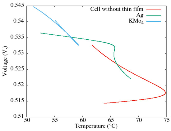
Figure 4.
Open circuit voltage vs. temperature of potassium permanganate coated solar cell, silver nanoparticles coated solar cell, and solar cell without thin film.
An analysis was conducted on the spectral transmission of thin films of various materials, given that the portion of solar energy converted into electrical current is directly related to the energy that passes through these materials. For this purpose, a Triad Spectroscopy Sensor AS7265x solar spectrum manufactured by SparkFun Electronics, headquartered in Niwot, CO, USA, was employed. This sensor detects electromagnetic radiation in the wavelength range from 400 nm to 900 nm, corresponding to the visible and near-infrared regions (see Figure 5) which presents the transmission spectrum of a thin film of potassium permanganate. In this case, light passes through the film deposited on the substrate, and the transmitted spectrum is measured. The measurements were obtained for KMnO4 on the substrate (purple line), the bare substrate or glass (black line), and the difference between the two spectra (green line). The results indicate that the peak energy, or maximum radiation, occurs between 450 nm and 630 nm. Similarly, Figure 5b shows the results for a thin film of Ag nanoparticles deposited on a glass substrate. The purple line corresponds to light transmitted through the Ag coated substrate, the black line to the substrate, and the dotted green line to the difference between the two spectra. Figure 5c presents the corresponding measurements for a thin film of ZnS. The most relevant comparison is shown in Figure 5d, where the transmission spectra of all films are plotted together. The ZnS layer showed partial transparency in the visible range, while CuS and PbS presented higher attenuation or dissipation of light, especially in wavelengths near the infrared region. These findings correlate with the electrical performance data, confirming that materials with better visible light transmission produced higher power output, likely due to reduced optical losses. The outline of the tests performed for spectrum measurement is shown in Figure 6.

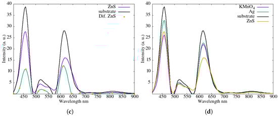
Figure 5.
Intensity irradiance versus wavelength on thin films over a glass substrate. (a) Thin film of KmnO4, (b) Thin film of Ag, (c) Thin film of ZnS and (d) Comparison of thin films.
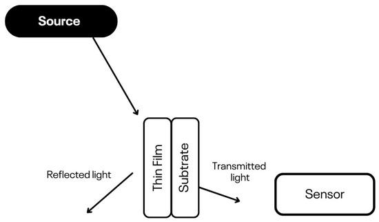
Figure 6.
Outline of the electromagnetic spectrum sensing system.
The higher curves Figure 5 correspond to films that allow greater transmission of solar radiation. The results are consistent with the temperature profile shown in Figure 3a: the substrate exhibits the highest transmission, followed by the Ag nanoparticle film, and finally the KMnO4 and ZnS films, which show similar transmission levels. This trend is consistent with the fact that lower transmitted energy results in a cooler surface, thereby reducing heating of the silicon solar cell. The Figure 7 presents an X-ray Photoelectron Spectroscopy (XPS) spectrum confirming that the materials employed experimentally in Section 2 are KMnO4, Ag, and ZnS. In each case, the energy corresponding to the characteristic peak of each element can be observed. The characteristic peaks corresponding to manganese (Mn 2p at 642 eV), silver (Ag 3d at 368 eV), and zinc (Zn 2p at 1022 eV) confirm the successful deposition of KMnO4, Ag, and ZnS films, respectively. The absence of additional peaks in the spectrum indicates confirming the purity and specificity of the chemical bath deposition process. These results validate that only the intended compounds were present on the surface of the cells after treatment.
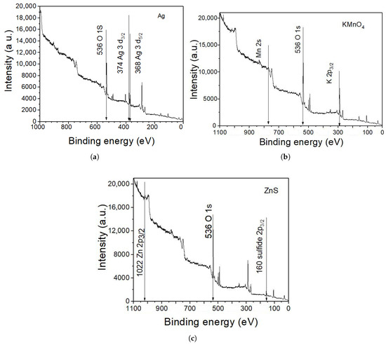
Figure 7.
XPS survey spectra of the samples: (a) Intensity vs. binding energy for Ag thin films; (b) Intensity vs. binding energy for KMnO4 thin films; (c) Intensity vs. binding energy for ZnS thin films.
3. Simulation with Transfer Matrix Method
We used the transfer matrix method (TMM) for simulation and then analyzed light incident on the (Silicon–thin film–Air), considering transverse electric (TE) polarized waves. The TMM consists of a multilayer system in which each layer has a defined thickness along the x axis, while the reflectance of the materials is represented along the y axis. Furthermore, the component of the wave vector perpendicular to the material interface is defined as with , where i represents the medium index.
Taking into account a single film bounded by and , its characteristic matrix is expressed in Equation (1). This matrix establishes the relation between the fields at one boundary of the film and the total fields at the opposite boundary. By iterative application of this procedure, the reflectance and transmittance of a multilayer structure was obtained.
From Equation (1), d denotes the thickness of the second medium, m represents the material of a given layer, the subscripts T refer to the transmitted fields at one interface, and the subscripts i indicate the total fields at the incident interface.
Figure 8 shows a bilayer system illuminated under normal incidence. The red line consists of a system with 50 nm thick Ag layer deposited on a 500 nm thick Si substrate. This configuration is used to evaluate the fraction of incident light reflected by the structure. The red curve indicates that nearly of the incident light is reflected, allowing only minimal energy transmission. In contrast, for the case of a 50 nm ZnS layer on a 500 nm Si substrate, the reflected energy is significantly lower, with reflectance strongly dependent on the incident wavelength and ranging approximately from to .
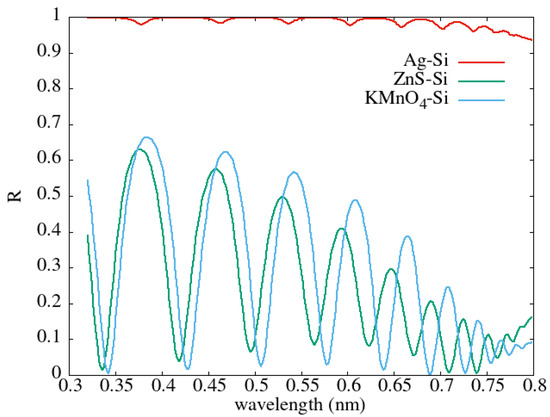
Figure 8.
Reflectance versus incident light wavelength in bi layer systems.
Additionally, the KMnO4–Si system exhibits a reflectance behavior similar to that of the ZnS–Si system, indicating that reflection is not the primary factor responsible for the observed enhancement in the voltage gain of the solar cells. Instead, this improvement is more likely attributed to heat dissipation rather than optical reflection. The simulation data were obtained at room temperature from the data set in [24], and the refractive index used for KMnO4 was n ≈ 1.334 [25].
4. Conclusions
The objective of this study was to determine whether thin-film coatings deposited via CBD, specifically KMnO4, Ag nanoparticles, and ZnS, could reduce operating temperature and improve the open-circuit voltage of commercial polycrystalline silicon solar cells under real outdoor irradiance conditions. The results show that only two coatings, potassium permanganate and silver nanoparticles, contributed positively to the voltage–temperature performance, whereas the ZnS, CuS, and PbS coatings did not produce improvements and in some cases reduced the voltage output.
Among all the materials evaluated, KMnO4 was the most effective coating, producing the lowest operating temperature and the largest voltage gain. KMnO4 treated cells exhibited an average temperature reduction of approximately 13.5 °C compared to the uncoated cell and achieved the highest voltage improvement (≈0.51%). This behavior is attributed to the reduced thermal load associated with the KMnO4 thin film, consistent with the transmission and reflectance analyses and with previous reports indicating that permanganate layers can favor heat dissipation. The second-best performance was obtained with Ag nanoparticles, which produced a moderate temperature reduction (≈6.3 °C on average) and a corresponding increase in open-circuit voltage due to enhanced scattering and reduced surface heating. The ZnS coating showed no measurable benefit, corroborated by both electrical and spectral transmission measurements.
These findings confirm the study’s hypothesis that thin-film coatings can mitigate thermal effects and improve the voltage response of polycrystalline silicon cells, and clearly identify KMnO4 as the coating that provided the greatest improvement under the conditions tested.
The limitations of this study must also be noted. (1) The experiments were conducted using small laboratory-scale solar cells (39 mm × 19 mm), which do not replicate the thermal mass, encapsulation structure, or heat-dissipation mechanisms of full-size photovoltaic modules; therefore, scale-up effects may differ. (2) Only the open-circuit voltage was measured; full I–V curves and power output (Pmax) were not obtained, limiting the assessment of complete device performance. (3) The CBD layers were deposited under controlled laboratory conditions, and film thickness, morphology, and long-term stability were not fully characterized (e.g., no SEM, profilometry, or durability testing). (4) Tests were performed on clear-sky days only, so performance under varying weather and irradiance stability remains unexamined.
Future work should therefore include full I–V characterization, module-level validation, detailed structural and morphological analysis of the coatings, and long-term outdoor testing to assess durability and performance under a wider range of environmental conditions.
Author Contributions
Conceptualization, J.M.G.-V. and H.A.P.-L.; methodology, J.M.G.-V., H.A.P.-L., M.F.S.V., I.M.S.-T. and S.G.R.-M.; software, J.M.G.-V.; validation, J.M.G.-V., M.F.S.V. and I.M.S.-T.; formal analysis, J.M.G.-V., I.M.S.-T. and S.G.R.-M.; investigation, J.M.G.-V., H.A.P.-L. and S.G.R.-M.; resources, J.M.G.-V., I.M.S.-T. and S.G.R.-M.; data curation, J.M.G.-V.; writing—original draft preparation J.M.G.-V., H.A.P.-L., M.F.S.V. and S.G.R.-M.; writing—review and editing, I.M.S.-T. All authors have read and agreed to the published version of the manuscript.
Funding
The authors express their gratitude to PROFAPI ITSON 2025-0549 and 2025-0527 for the financial support provided for this research work.
Data Availability Statement
Data underlying the results presented in this paper are not publicly available at this time but may be obtained from the authors upon reasonable request.
Conflicts of Interest
The authors declare no conflicts of interest.
Appendix A
The CBD process used in this study was carried out according to a standardized procedure to ensure reproducibility across all coatings. All precursor solutions were prepared using deionized distilled water, and each reagent was diluted to the required molar concentration prior to the deposition stage. In the case of ZnS, triethanolamine and thiourea were previously adjusted to their corresponding pH values to stabilize the formation of the chemical complex. For the other substances used in the coatings, the reagents were purchased commercially and then diluted in deionized distilled water to obtain the appropriate concentration. In all cases, the solar cells were immersed for 1.5 h in a single continuous cycle under constant agitation, ensuring homogeneous coverage during the process. The detailed formulations for each material are presented below.
- Formulation list for ZnS thin films.
- Add 7 mL of 0.1 M zinc acetate solution.
- Add 2 mL of triethanolamine (TEA), pre-adjusted to 1 M with a pH of 10.
- Add 50 mL of ammonia solution (NH3), prepared at 0.1 M.
- Add 7 mL of thiourea solution, prepared at 1 M with a pH of 6.
- Stir the mixture continuously and maintain the temperature at 80 °C for one hour.
- Immerse the solar cells for 1.5 h in a single continuous cycle under constant stirring.
- Formulation list for Ag nanoparticles.
- Add 10 mL of deionized H2O as solvent.
- Dissolve the commercial-grade Ag precursor to obtain a 0.1 M solution.
- Maintain the solution under continuous stirring at 25 ± 1 °C.
- Immerse the solar cells for 1.5 h in a single continuous cycle with constant agitation.
- Formulation list for preparing KMnO4 thin films.
- Add 10 mL of deionized H2O as solvent.
- Dissolve commercial-grade KMnO4 to obtain a 0.1 M solution.
- Maintain the solution under continuous stirring at 25 ± 1 °C.
- Immerse the solar cells for 1.5 h in a single continuous cycle under constant stirring.
References
- Ramírez, D.; Jaramillo, F. Design of two-dimensional perovskite solar cells with superior efficiency and stability. Rev. Fac. Ing. Univ. Antioq. 2021, 100, 67–74. [Google Scholar] [CrossRef]
- Green, M.; Dunlop, E.; Hohl-Ebinger, J.; Yoshita, M.; Kopidakis, N.; Hao, X. Solar cell efficiency tables (version 57). Prog. Photovolt. Res. Appl. 2020, 29, 3–15. [Google Scholar] [CrossRef]
- Sun, Z.; Chen, X.; He, Y.; Li, J.; Wang, J.; Yan, H.; Zhang, Y. Toward Efficiency Limits of Crystalline Silicon Solar Cells: Recent Progress in High-Efficiency Silicon Heterojunction Solar Cells. Adv. Energy Mater. 2022, 12, 2200015. [Google Scholar] [CrossRef]
- Joon, C.J.; Jin, K.C.W. Design of Augmented Cooling System for Urban Solar PV System. MATEC Web Conf. 2021, 335, 03002. [Google Scholar] [CrossRef]
- Green, M.A.; Dunlop, E.D.; Hohl-Ebinger, J.; Yoshita, M.; Kopidakis, N.; Hao, X. Solar Cell Efficiency Tables (Version 66). Prog. Photovoltaics Res. Appl. 2025, 29, 657. [Google Scholar] [CrossRef]
- Lu, Z.H.; Yao, Q. Energy analysis of silicon solar cell modules based on an optical model for arbitrary layers. Sol. Energy 2007, 81, 636–647. [Google Scholar] [CrossRef]
- Shamaeizadeh, A.; Astaraei, F.R.; Kasaeian, A. Investigating the effect of adding silver nanoparticles to hybrid crystalline silicon solar cells. Results Opt. 2023, 14, 100598. [Google Scholar] [CrossRef]
- Fraser, R.; Gîrtan, M. A Selective Review of Ceramic, Glass and Glass–Ceramic Protective Coatings: General Properties and Specific Characteristics for Solar Cell Applications. Materials 2023, 16, 3906. [Google Scholar] [CrossRef] [PubMed]
- Farooq, W.; Tu, S.; Kazmi, S.A.A.; Rehman, S.u.; Khan, A.D.; Khan, H.A.; Waqas, M.; Rehman, O.u.; Ali, H.; Noman, M. Novel perovskite solar cell with Distributed Bragg Reflector. PLoS ONE 2021, 16, e0259778. [Google Scholar] [CrossRef]
- France, R.M.; Espinet-Gonzalez, P.; Ekins-Daukes, N.J.; Guthrey, H.; Steiner, M.A.; Geisz, J.F. Multijunction Solar Cells With Graded Buffer Bragg Reflectors. IEEE J. Photovolt. 2018, 8, 1608–1615. [Google Scholar] [CrossRef]
- Zhu, Y.; Shu, L.; Fan, Z. Recent Progress on Semi-transparent Perovskite Solar Cell for Building-integrated Photovoltaics. Chem. Res. Chin. Univ. 2020, 36, 366–376. [Google Scholar] [CrossRef]
- Patil, P.; Sangale, S.S.; Kwon, S.-N.; Na, S.-I. Innovative Approaches to Semi-Transparent Perovskite Solar Cells. Nanomaterials 2023, 13, 1084. [Google Scholar] [CrossRef]
- Raja, W.; Schmid, M.; Toma, A.; Wang, H.; Alabastri, A.; Zaccaria, R.P. Perovskite Nanopillar Array Based Tandem Solar Cell. ACS Photonics 2017, 4, 2025–2035. [Google Scholar] [CrossRef]
- Amalathas, A.P.; Alkaisi, M. Nanostructures for Light Trapping in Thin Film Solar Cells. Micromachines 2019, 10, 619. [Google Scholar] [CrossRef]
- Efaz, E.T.; Rhaman, M.M.; Imam, S.A.; Bashar, K.L.; Kabir, F.; Mourtaza, M.D.E.; Sakib, S.N.; Mozahid, F.A. A review of primary technologies of thin-film solar cells. Eng. Res. Express 2021, 3, 032001. [Google Scholar] [CrossRef]
- Saive, R. Light trapping in thin silicon solar cells: A review on fundamentals and technologies. Prog. Photovolt. Res. Appl. 2021, 29, 1125–1137. [Google Scholar] [CrossRef]
- Rouhbakhshmeghrazi1, A.; Madadi, M. Novel Design of polycrystalline CdTe/Si Tandem Solar Cells Using SiO2/TiO2 Distributed Bragg Reflector. Tecciencia 2020, 15, 67–75. [Google Scholar] [CrossRef]
- Maalouf, A.; Okoroafor, T.; Jehl, Z.; Babu, V.; Resalati, S. A comprehensive review on life cycle assessment of commercial and emerging thin-film solar cell systems. Renew. Sustain. Energy Rev. 2023, 186, 113652. [Google Scholar] [CrossRef]
- Minnaert, B.; Veelaert, P. Efficiency simulations of thin film chalcogenide photovoltaic cells for different indoor lighting conditions. Thin Solid Film 2011, 519, 7537–7540. [Google Scholar] [CrossRef]
- Yamamoto, K.; Nakajima, A.; Yoshimi, M.; Sawada, T.; Fukuda, S.; Suezaki, T.; Ichikawa, M.; Koi, Y.; Goto, M.; Meguro, T.; et al. A high efficiency thin film silicon solar cell and module. Sol. Energy 2004, 77, 939–949. [Google Scholar] [CrossRef]
- Jiang, Y.; Shen, H.; Zheng, C.; Pu, T.; Wu, J.; Rui, C.; Yang, W.; Li, Y. Nanostructured multi-crystalline silicon solar cell with isotropic etching by HF/KMnO4. Phys. Status Solidi A 2017, 214, 1600703. [Google Scholar] [CrossRef]
- Pylnev, M.; Nishikubo, R.; Ishiwari, F.; Wakamiya, A.; Saeki, A. Sequential Deposition of Diluted Aqueous SnO2 Dispersion for Perovskite Solar Cells. Sol. RRL 2024, 8, 2400415. [Google Scholar] [CrossRef]
- Gangisetty, G.; Zevenhoven, R. A Review of Nanoparticle Material Coatings in Passive Radiative Cooling Systems Including Skylights. Energies 2023, 16, 1975. [Google Scholar] [CrossRef]
- Polyanskiy, M. RefractiveIndex.INFO-Refractive Index Database. 2015. Available online: https://refractiveindex.info/ (accessed on 1 October 2025).
- Irawati, N.; Nur; Rahman, H.A.; Yasin, M.; Ahmad, H.; Harun, S.W. Potassium permanganate (KMnO4) sensing based on microfiber sensors. Appl. Opt. 2017, 56, 224. [Google Scholar] [CrossRef]
Disclaimer/Publisher’s Note: The statements, opinions and data contained in all publications are solely those of the individual author(s) and contributor(s) and not of MDPI and/or the editor(s). MDPI and/or the editor(s) disclaim responsibility for any injury to people or property resulting from any ideas, methods, instructions or products referred to in the content. |
© 2025 by the authors. Licensee MDPI, Basel, Switzerland. This article is an open access article distributed under the terms and conditions of the Creative Commons Attribution (CC BY) license (https://creativecommons.org/licenses/by/4.0/).