Abstract
As a core component of both the ship propulsion system and mission-critical equipment, shipboard motors are undergoing a technological transition from traditional fault diagnosis to multi-physical-field collaborative modeling and integrated intelligent maintenance systems. This paper provides a systematic review of recent advances in shipboard motor fault monitoring, with a focus on key technical challenges under complex service environments, and offers several innovative insights and analyses in the following aspects. First, regarding the fault evolution under electromagnetic–thermal–mechanical coupling, this study summarizes the typical fault mechanisms, such as bearing electrical erosion, rotor eccentricity, permanent magnet demagnetization, and insulation aging, and analyzes their modeling approaches and multi-physics coupling evolution paths. Second, in response to the problem of multi-source signal fusion, the applicability and limitations of feature extraction methods—including current analysis, vibration demodulation, infrared thermography, and Dempster–Shafer (D-S) evidence theory—are evaluated, providing a basis for designing subsequent signal fusion strategies. With respect to intelligent diagnostic models, this paper compares model-driven and data-driven approaches in terms of their suitability for different scenarios, highlighting their complementarity and integration potential in the complex operating conditions of shipboard motors. Finally, considering practical deployment needs, the key aspects of monitoring platform implementation under shipborne edge computing environments are discussed. The study also identifies current research gaps and proposes future directions, such as digital twin-driven intelligent maintenance, fleet-level PHM collaborative management, and standardized health data transmission. In summary, this paper offers a comprehensive analysis in the areas of fault mechanism modeling, feature extraction method evaluation, and system deployment frameworks, aiming to provide a theoretical reference and engineering insights for the advancement of shipboard motor health management technologies.
1. Introduction
Shipboard motors, as the core components of marine propulsion systems and critical power equipment, perform multiple functions, including power output, energy conversion and mission support. Their reliability directly affects a vessel’s operational effectiveness and navigation safety [1,2,3]. Compared to land-based motors, shipboard motors operate year-round in extreme marine environments, characterized by salt spray, high humidity, strong vibration and complex electromagnetic interference, exhibiting significantly coupled multi-physics fault mechanisms that render traditional prognostics and health management (PHM) methods inadequate for marine applications [4].
With recent developments in new naval technologies, such as “all-electric propulsion” and “Integrated Power Systems (IPS)”, motor system complexity has increased substantially [5]. For instance, the U.S. DDG-1000 and UK Type 45 destroyers employ medium-voltage variable frequency drive technology, introducing new failure risks, including high-frequency harmonics, electromagnetic interference and bearing electrical erosion. Meanwhile, the application of high-power permanent magnet synchronous motors in carrier and submarine propulsion systems has raised concerns about demagnetization risks, thermal management and insulation degradation. These advancements impose higher requirements for shipboard motor fault monitoring and intelligent maintenance.
Shipboard motors face unique challenges.
(1) High salt spray and humidity corrosion: The marine environment’s high salt spray and humidity accelerate motor insulation aging, leading to stator winding partial discharge and bearing corrosion [6,7,8]. For example, auxiliary motors on destroyers operating in the South China Sea’s high-humidity, high-salinity environment experienced 40% insulation resistance reduction after 3 years, significantly faster than land-based counterparts. Salt deposition may also cause electrical tracking, threatening high-voltage motor safety.
(2) Mechanical vibration and shock loads: Shipboard motors endure main engine start-stop impacts, wave-induced hull vibrations, and instantaneous torque transients from electric propulsion systems (e.g., full-speed reverse operations) [9,10]. The U.S. Office of Naval Research (ONR) reports that 45% of marine propulsion motor bearing failures relate to shaft torsional vibration. Traditional vibration monitoring methods (e.g., ISO 10816 standard [11]) are prone to false alarms in ships’ broadband vibration environments.
(3) Power electronics coupling interference: Medium-voltage inverters’ high dv/dt pulses (up to 10 kV/μs) induce bearing electrical discharge machining (EDM) and localized insulation damage in shipboard motors. Research shows SiC-based inverters reduce stator winding partial discharge inception voltage by 15–20%, exacerbating insulation degradation risks.
(4) Fault characteristic differences between traditional and electric propulsion systems: Mechanical drive ships’ main motor failures typically manifest as mechanical wear (e.g., gearbox degradation), while electric propulsion system faults concentrate on electromagnetic–thermal coupling issues. For instance, the UK Queen Elizabeth-class carrier’s 20 MW propulsion motor experienced irreversible permanent magnet demagnetization due to cooling system failure—a failure mode virtually nonexistent in traditional diesel systems.
Shipboard motor fault monitoring holds significant military value and forms a crucial foundation for intelligent O&M systems [12,13]. Militarily, as naval vessels’ core power devices, propulsion motor failures may cause total blackouts, radar failures or electromagnetic catapult malfunctions. The UK Type 45 destroyer’s propulsion motor failure-induced blackout prompted a £250 million monitoring system upgrade by the UK Ministry of Defense. To enhance operational readiness and fault response capabilities, the U.S. Navy has fully deployed the “Integrated Condition Assessment System (ICAS)” on new vessels, mandating real-time health prediction and Remaining Useful Life (RUL) assessment for critical equipment such as motors.
For engineering applications, the International Maritime Organization (IMO) issued MSC.1/Circ.1580 guidelines in 2017 [14], recommending that all new ships install condition-based monitoring (CBM) predictive maintenance systems [15]. Classification societies and shipping companies report that intelligent fault monitoring systems can reduce shipboard motor O&M costs by approximately 30% and unscheduled downtime by 45%. For example, Maersk Line’s current-vibration combined monitoring for auxiliary motors prevents millions in annual losses.
Moreover, shipboard motor intelligent monitoring technology demonstrates significant military–civilian conversion potential. Relevant achievements have been applied to high-end marine equipment, such as offshore wind platforms and deep-sea submersibles. For instance, China’s “Jiaolong” employs an online motor insulation monitoring system derived from naval motor condition monitoring projects, achieving 92% warning accuracy in complex marine environments.
In summary, shipboard motors’ multi-physics coupled failure mechanisms in complex operating environments, sensitive degradation processes under electromagnetic disturbances, and urgent needs for intelligent diagnosis and predictive maintenance collectively constitute critical research directions for smart ship O&M technologies. While existing studies have explored motor condition recognition and localized fault diagnosis, systematic reviews remain lacking for multi-source fault modeling, data fusion analysis methods and digital twin integrated systems in naval contexts, particularly regarding implementation pathways for military and high-reliability engineering applications.
Therefore, this research carries significant strategic and engineering value. With the development of all-electric ships and integrated power systems, motors, as marine power cores, face multiple challenges, including high salt spray corrosion, strong mechanical vibration and complex electromagnetic interference, with their reliability directly impacting naval combat effectiveness and navigation safety. This study systematically reviews technological evolution from traditional mechanism analysis to modern intelligent diagnostics, providing theoretical support and technical solutions to enhance shipboard motor operational reliability while advancing maintenance paradigms from passive repair to active prevention. Militarily, this research addresses critical technological bottlenecks constraining naval equipment development, improving vessel operational readiness and mission success rates. For civilian applications, the findings can be extended to major projects, such as marine equipment and offshore wind power, generating substantial economic benefits. Furthermore, the proposed intelligent O&M framework offers important guidance for implementing full lifecycle health management and transforming equipment support models, providing valuable references for China’s shipboard power system technology development.
2. Fault Mechanisms and Characteristic Analysis of Shipboard Motors
Shipboard motors are widely used in main propulsion systems, auxiliary units, and electric drive equipment, operating under complex working conditions with significant load impacts while being constantly exposed to high-salt, high-humidity, and high-electromagnetic-interference environments. Their failure mechanisms exhibit distinctive multi-physical field coupling characteristics, including complex interactions, such as electromagnetic–thermal–mechanical coupling, mechanical shock-vibration amplification, and power electronic stress-insulation degradation. Conducting in-depth mechanism modeling of their typical failure modes and extracting effective condition characteristic signals are prerequisites for achieving highly reliable diagnostics and intelligent maintenance. Specifically, faults in shipboard motors often originate from the coupling effects of multiple physical fields, including electrical, magnetic, thermal, and mechanical domains, and, thus, require in-depth characterization from the perspectives of coupling mechanism modeling, signal interaction effects, and nonlinear influences.
2.1. Typical Fault Classification and Physical Modeling
The fault characteristics of shipboard motors differ significantly depending on their functional roles. Main propulsion motors mainly exhibit bearing electrical erosion and rotor dynamic eccentricity—the former caused by shaft current discharge leading to metal damage and the latter originating from the mechanical–electromagnetic coupling effects induced by propulsion load impacts [16,17]. Auxiliary motor faults are concentrated in insulation aging and cooling failures, where hot and humid environments accelerate material degradation, and biological fouling reduces cooling system performance. Electric propulsion motors display typical power electronic faults, including high-frequency partial discharge caused by PWM inverters, and permanent magnet demagnetization resulting from combined high-temperature and harmonic effects. All three fault types require analysis incorporating multi-physical field coupling effects, reflecting the special failure mechanisms of shipboard motors under complex operating conditions.
- (1)
- Fault Mechanisms of Main Propulsion Motors
- 1)
- Bearing Electrical Erosion
The main propulsion motor bearings on ships are prone to various types of damage in complex marine environments, among which electrical corrosion is a typical failure mode. The higher the current density, the more severe the electrical erosion of the bearing. In addition, mechanical factors, such as rolling element pitting, cage looseness, and lubricant degradation, are also major causes of bearing failures, especially under propulsion impact loads and long-term operation, where compound failures are more likely to occur. For unified modeling, this paper takes the shaft current density J (A/m2) as an example, which is expressed as
where σ represents the lubricant conductivity (S/m), where higher conductivity (e.g., due to saltwater content) makes shaft current more likely to form; E denotes the electric field (V/m) formed by shaft voltage across bearing clearance, where increased shaft voltage (e.g., caused by PWM inverters) will significantly enhance electric field intensity; v is the bearing rotational speed (m/s), where the v × B term contribution increases during high-speed rotation (e.g., shipboard main motors typically operate above 1000 rpm); and B is the magnetic flux density (T), where magnetic circuit asymmetry or rotor eccentricity will increase leakage flux.
The formation rate of discharge-induced electrical erosion pits (m/s), which directly determines bearing life, must be maintained below 0.1 μm/hour for shipboard motors (per DNV GL standards). Its expression is given by
where D is the erosion pit depth (m); Ea is the activation energy (J/mol), with typical bearing steels having Ea values of 25~50 kJ/mol, where high temperature environments reduce activation energy; R is the gas constant (J/(mol·K)); T is the bearing operating temperature (K), where shipboard motor bearings are typically maintained below 353 K (80 °C), with every 10 °C temperature increase accelerating corrosion rate by 1.5~2 times; and k is the material corrosion constant (m3·s−1·A−2), where the k value for 316 stainless steel bearings is two orders of magnitude higher than that of ceramic bearings.
- 2)
- Rotor Eccentricity (Propulsion Load Impact)
The unbalanced magnetic pull (UMP) Fecc induced by dynamic eccentricity is the primary cause of vibration, expressed as
where μ0 is the vacuum permeability (H/m); r is the rotor radius (m), where, as the rotor radius r increases, the UMP exhibits a linear growth trend; l is the axial length of the core (m), where the length increase will amplify the magnetic pull; N is the number of turns of stator windings, where the square relationship between the number of turns affects the UMP and high power density motors need to optimize the design of windings; I is the rms stator current (A); δ is the amount of eccentricity (m), where a 10% reduction in air gap increases UMP by about 23% (need to control assembly tolerances); and g is the air gap length (m), where the eccentricity under ship shock loads up to 0.1~0.3 mm (ISO 1940-1 [18] requirements of the rotor unevenness of <G2.5 level). The expression for the eigenfrequency fecc of an eccentric fault is
where fr is the rotor mechanical frequency (Hz); fs is the power supply frequency (Hz); and o is the number of harmonics, k ∈ Z.
- (2)
- Auxiliary Motor Failure Mechanism
Auxiliary motors are usually installed in high-humidity and hot compartments in ships, and their insulation aging is a particular problem. Based on the modified Arrhenius model, the insulation life service L can be expressed as
where L0 is the base life constant (years), with life under standard operating conditions (25 °C, 50%RH); Ea is the activation energy of the material (kJ/mol), determined by thermogravimetric analysis (TGA); β is the humidity coupling coefficient (kJ/(mol-%RH)); H is the relative humidity (%RH), where the measured humidity in the chamber is the reference humidity (50%RH); H0 is the base value of the standard operating conditions; and n is the humidity acceleration index, fitted by the humidity–heat cycle test (typical value 0.5~1.2).
- (3)
- Propulsion Motor Failure Mechanisms
- 1)
- Permanent Magnet Demagnetization
Affected by thermal–harmonic coupling, permanent magnets are prone to irreversible demagnetization [19]. Based on the critical condition of irreversible demagnetization of permanent magnets under the thermal–harmonic coupling effect, the expression of the demagnetization critical magnetic field strength, Hdemag (A/m), is given as
where Hc0 is the coercivity (A/m) at the reference temperature (25 °C); α is the coercivity temperature coefficient (1/°C); T1 is the permanent magnet operating temperature (°C); Tref is the reference temperature (usually 25 °C); γ is the harmonic demagnetization susceptibility factor, which is calibrated by harmonic spectral analysis experiments (typically 0.1~0.3); Ik is the amplitude of the kth harmonic current (A); I0 is the fundamental wave current rated value (A); fk is the kth harmonic frequency (Hz); and n1 is the frequency attenuation index, the material high-frequency demagnetization characteristic test (typical 0.5~1.2).
- 2)
- Stator Winding Partial Discharge (PWM inverter stress)
The discharge statistical property F(t) conforms to a three-parameter Weibull distribution [20] with the expression
where ω is the position parameter (h); t is the running time (h); η is the scale parameter (h); and ϕ is the shape parameter, where β < 1 denotes early failure, β = 1 denotes random failure, and β > 1 denotes wear failure (typical value of shipboard motors is 1.5~2.5).
It should be noted that there exists a certain coupling relationship between insulation degradation and partial discharge. Partial discharge is not only a manifestation of the insulation aging process but also acts in turn to accelerate the deterioration of insulation performance. Moreover, high-frequency current pulses generated by PWM inverters significantly enhance local electric field stress, thereby further exacerbating the degradation of insulation materials.
Table 1 represents a comparative analysis of typical fault classifications of ship motors. As shown in Table 1, shipboard motor faults can be categorized into four major types, mechanical, electrical, insulation, and cooling-related faults, each corresponding to different causes and characteristic signal patterns. Mechanical faults, such as bearing electrical erosion and rotor eccentricity, are often characterized by coupled features of high-frequency vibration and current disturbances. Electrical faults, such as broken rotor bars and partial discharges, mainly manifest as anomalies in current spectra and changes in insulation parameters. It is noteworthy that although permanent magnet demagnetization and insulation aging belong to different categories, both exhibit performance degradation under thermal stress, indicating the necessity of monitoring multiple hidden risks in electro-thermal coupled scenarios. Additionally, while cooling system faults are not intrinsic to the motor, they can be detected at an early stage through temperature differentials and infrared anomalies, highlighting the practical significance of boundary coupling issues in shipboard environments. The information in the table provides a solid basis for subsequent fault modeling and diagnostic path selection by offering classification criteria and feature-matching guidance.

Table 1.
Comparative analysis of typical Fault classification of shipboard motors.
Table 2 represents the comparison of typical failure characteristic frequencies of ship motors. As shown in Table 2, different fault types exhibit distinct frequency-domain distributions [21]. Bearing galvanic corrosion typically excites mid-to-high-frequency components (500 Hz–10 kHz) in both vibration and current harmonic signals, making it suitable for identification using envelope demodulation in conjunction with high-resolution current analysis [22]. In contrast, rotor broken strip and eccentricity faults are mainly concentrated in the low-frequency range (25–75 Hz), requiring enhanced resolution and noise suppression strategies in that band [23,24]. Partial discharges in stator windings occur in the hundreds of kilohertz to megahertz range, placing stringent demands on sensor bandwidth and anti-interference capability [25]. These frequency distribution characteristics provide a theoretical basis for fault signal extraction and indicate that in multi-source fusion systems, frequency-optimized acquisition and processing strategies should be adopted to ensure coverage across a wide range of physical representation frequencies.
Table 2.
Comparison of typical failure characteristic frequencies of ship motors.
Table 3 indicates a hazard level assessment of shipboard motor failures. It classifies typical faults based on average repair time and system impact, highlighting the engineering severity differences among fault types. Category I faults, such as irreversible demagnetization of permanent magnets, require factory-level maintenance and severely affect propulsion capability, indicating the necessity of early warning mechanisms and critical demagnetization condition modeling. Category II faults, such as Stator winding turn-to-turn short circuit, may trigger grid outages and thus demand fast isolation mechanisms within the protection system. In contrast, Category III and IV faults do not lead to system failure but pose potential threats to operational stability, suggesting the need to improve real-time monitoring accuracy and minor fault tolerance. This classification helps prioritize fault types in monitoring systems and guides sensor deployment and alarm level configuration.
Table 3.
Hazard class assessment of shipboard motor failures.
Table 4 indicates a comparison of the applicability of shipboard motor inspection techniques. It systematically compares common diagnostic methods in terms of their effectiveness for typical fault types, adaptability to shipboard environments, and corresponding improvement directions. It is evident that each technique has certain limitations when applied in complex onboard conditions. For instance, current harmonic analysis is sensitive to rotor breakage and eccentricity faults and offers the advantage of being non-intrusive; however, its signal-to-noise ratio significantly degrades under strong electromagnetic interference. Enhancements in this method rely on SiC-based devices and wide-band measurement strategies. Envelope demodulation of vibration signals is effective for early detection of bearing damage and mechanical looseness, but the presence of hull vibration introduces substantial background noise, limiting the accuracy of traditional time-domain methods. Current research is shifting toward deep learning-driven automatic time-frequency feature extraction. Infrared thermal imaging, owing to its intuitive visualization, is widely used for insulation aging and poor contact detection; however, airflow disturbances within the cabin often cause thermal image drift, necessitating multi-view reconstruction and emissivity correction techniques. High-frequency partial discharge detection exhibits high sensitivity for winding insulation faults, yet it is easily affected by PWM switching noise. Recent studies have proposed denoising enhancements through data augmentation and filtering techniques to improve practical performance. In summary, although each technology demonstrates advantages in specific fault scenarios, their effectiveness in complex shipboard conditions still depends heavily on hardware optimization and algorithmic support. Therefore, it is essential to establish a multi-channel collaborative compensation mechanism to ensure robust monitoring.
Table 4.
Comparison of the applicability of shipboard motor inspection techniques.
To further validate the engineering applicability of typical fault mechanisms and diagnostic methods, Table 5 summarizes five representative shipboard motor fault cases, comparing key indicators, cause analysis, and improvement insights. First, the main propulsion motor of the British Type 45 destroyer suffered bearing electro-corrosion and overheating failure due to the absence of shaft current monitoring and concurrent cooling faults, indicating a typical electro–thermal coupling risk between shaft current density and temperature rise. This suggests the need for integrated sensing devices to enable multi-parameter early warning. Second, a domestic destroyer’s propulsion motor experienced permanent magnet demagnetization, with a decline in back-EMF and increased harmonic THD indicating a magnetic–thermal–electrical coupling degradation pathway. This highlights the importance of PWM harmonic suppression and redundancy in oil cooling system design. In the case of insulation breakdown in an auxiliary motor of a Norwegian cruise ship, a significant rise in tanδ and excessive partial discharge were strongly influenced by a high-humidity environment, emphasizing the need to understand insulation degradation under thermal–humidity–electrical coupling and to integrate multiple sensing modalities. Another case involved a research vessel whose propulsion motor suffered bearing failure induced by rotor eccentricity, exposing the coupling between mechanical misalignment and impact vibration, thus suggesting the adoption of envelope demodulation combined with electromagnetic signal-based diagnostics. Lastly, a U.S. Navy LCS ship experienced a rapid rise in temperature difference and a sharp drop in flow rate due to marine biofouling blockage in the cooling channel, reflecting the challenges posed by fluid–thermal–biological interactions on motor operation stability. Infrared imaging algorithms must also account for dynamic surface thermal resistance compensation. In summary, these cases demonstrate complex couplings among multi-physics interactions, sensing limitations, and structural design weaknesses, offering critical engineering insights for multisource sensing fusion, fault mechanism modeling, and diagnostic strategy optimization in intelligent shipboard motor health monitoring systems.
Table 5.
Comparative analysis table of typical failure cases of shipboard motors.
2.2. Fault Feature Signal Extraction
Multi-parameter synergistic analysis methods are required for the monitoring of shipboard electric motor faults [26,27]. In practical monitoring signals, vibration, temperature, and current often exhibit superimposed characteristics resulting from multi-physics interactions. For example, local failure in the cooling system can lead to winding temperature rise, which in turn enhances partial discharge and manifests as high-frequency noise in the current signal. Therefore, during feature extraction, it is essential to consider the underlying physical coupling pathways among these signals. Joint modeling and collaborative analysis should be employed to enhance the physical consistency and accuracy of diagnostic results. Motor current signature analysis (MCSA) achieves early warning of electrical faults by identifying spectral features, while vibration envelope demodulation technique effectively captures modulation features of mechanical faults. Temperature field monitoring reveals abnormal heating areas through infrared thermal imaging, providing a thermodynamic diagnosis basis. In practical application, it is necessary to build a current–vibration–temperature multi-source information fusion system, and use intelligent decision-making algorithms to comprehensively study and judge all kinds of monitoring data, so as to significantly improve the accuracy and reliability of fault diagnosis under complex working conditions. This integrated monitoring strategy is fully adapted to the state assessment needs of shipboard motors under special working environments.
(1) Current Harmonic Analysis
For rotor bar breakage, rotor eccentricity, and bearing mechanical faults in shipboard motors, these operating conditions typically induce characteristic frequency components in the stator current signal. The commonly used expression for the characteristic fault frequency ffault is
where f0 is the base frequency of the power supply (Hz), where the ship’s power grid is usually 50 Hz or 60 Hz, the inverter drive needs to be tracked in real time; s is the slew rate, where s increases when the load is increased (typical ship’s motor s = 0.01∼0.05); p is the number of pairs of poles, where the more pairs of poles, the lower the eigenfrequency (e.g., the 10-pole motor ffault is 60% lower than that of a 4-pole motor); k0 is the characteristic order of the faults; and m is the sideband modulation order, where usually m = 1 (first order sideband), and higher-order components may appear in severe faults.
To reduce the interference of the spectrum leakage on the fault signal, an improved sliding window DFT algorithm is often used for calculation.
(2) Vibration Envelope Demodulation
Mechanical structure faults are characterized by extracting the envelope signal via the Hilbert transform [28], with the corresponding expression given as
where H[x(t)] is the resolved signal with the following expression:
The spectral analysis after envelope demodulation can reveal modulation frequency components, reflecting the periodic variations of impact signals caused by mechanical faults, such as bearing rolling element defects and inner or outer ring damages. This process demodulates the high-frequency vibration carrier into a low-frequency envelope signal, and extracts characteristic frequencies through the Fourier transform, thereby enabling accurate identification and localization of early-stage faults.
(3) Temperature Field Analysis
Temperature anomalies often originate from cooling faults or insulation hotspots, and the reconfiguration optimization problem can be described as
where TIR is the measured temperature matrix of infrared thermal image (K), the spatial resolution depends on the pixels of infrared camera (e.g., 640 × 512), and the emissivity correction needs to be performed (ε ≈ 0.8~0.9 on the surface of the ship’s electric motor). TFEM is the finite element temperature field solution vector (K), where the mesh should be matched with the resolution of the thermal image (usually 500,000~1,000,000 cells), and the boundary conditions include the parameter of forced air cooling/water cooling. The boundary conditions include forced air/water cooling parameters. λ is the regularization factor used in thermal field inversion (through cross-validation), typically ranging from 1 × 10 −3 to 1 × 10⁻⁵, which controls the smoothness of the solution; and KJ is the mapping matrix of the infrared camera and the finite element model.
(4) Multisource Fusion
To fuse sensor outputs, such as current, vibration, and thermal images, Dempster–Shafer evidence theory [29] is often used in uncertain environments, where the basic probability assignments of two independent sources of evidence are set to be m1 and m2, respectively, and their synthesized basic probability assignments (BPA), BPAm = m1⊕m2, are defined as
where Θ is the identification framework, the set of all possible propositions; and m1 and m2 are the underlying probability distribution functions of the two sources of evidence.
In addition to D-S evidence theory, commonly used multi-source fusion methods also include Bayesian inference and fuzzy logic. Bayesian inference is suitable for scenarios with sufficient prior knowledge and complete data. It updates belief degrees based on Bayes’ theorem and offers high computational efficiency when sensor outputs are stable. However, it is prone to fusion distortion when information is partially missing or when evidence conflict is significant. Fuzzy logic, on the other hand, handles imprecise information through membership functions and is applicable in environments with vague states or unclear decision boundaries, but it lacks effective mechanisms for suppressing evidence conflict. In comparison, D-S evidence theory does not require prior probabilities and is more suitable for shipboard applications with strong uncertainty, such as sensor failure and interference noise.
Table 6 indicates engineering validation data. As shown in Table 6, integrating shipboard motor fault mechanism modeling with multi-physical signal extraction methods can effectively enhance the accuracy and reliability of fault diagnosis. For example, in the case of bearing electro corrosion, the combination of MCSA and envelope demodulation achieved a recognition accuracy of 92.3%, demonstrating the practical applicability of this approach for fault identification. For insulation aging faults, the integration of temperature field monitoring with the Arrhenius accelerated aging model resulted in a prediction error within ±7.5%, indicating strong potential for thermal rise prediction and service life assessment. In the context of permanent magnet demagnetization, an analysis method based on harmonic component variation and critical operating point modeling yielded an identification accuracy of 89.1%, confirming its effectiveness in monitoring magnetic field degradation trends. Overall, Table 6 confirms the positive impact of multi-physics modeling and composite detection techniques in enhancing the recognition capability of key shipboard motor faults, particularly in highly autonomous systems with constrained onboard space and limited human intervention.
Table 6.
Engineering validation data.
Table 6, respectively, shows that the combination of shipboard motor fault mechanism modeling and multi-physical quantity signal extraction methods can significantly improve the reliability of fault diagnosis and provide theoretical support for the intelligent operation and maintenance system.
Table 7 presents the multi-sensor fusion diagnostic results for an integrated electric propulsion system. It further illustrates the typical outcomes achieved in practical applications through multi-sensor fusion. Taking bearing electrical erosion as an example, the confidence levels obtained from current, vibration, and temperature sensors were 0.65, 0.72, and 0.58, respectively. After fusion, the synthesized confidence increased to 0.81, with a conflict factor K of only 0.12, indicating strong consistency and complementarity among the data sources. In contrast, for permanent magnet demagnetization faults, the vibration sensor exhibited a low confidence level (0.15), which conflicted with the other signals and led to a higher conflict factor of 0.34. This suggests that the system should pay particular attention to source weighting and conflict resolution strategies. Furthermore, in scenarios where the conflict factor K reached as high as 0.61, the conflict warning mechanism was triggered, which is suitable for risk alerts under complex conditions, such as multi-fault interference or sensor failure. Table 7 demonstrates that multi-source sensor fusion not only enhances the robustness of diagnostic decisions but also provides a data foundation and decision support for dynamic perception, real-time decision making, and fault tolerance in shipboard intelligent maintenance systems.
Table 7.
Multi-sensor fusion diagnostic results of an integrated electric propulsion system.
Table 8 indicates how the D-S theory of evidence compares to other approaches (★ denotes one attained unit of capability or performance, whereas ☆ denotes one unattained unit within the five-level assessment scale). As shown in Table 8, different information fusion methods exhibit distinct advantages in handling uncertainty, computational efficiency, and adaptability to shipboard environments. Among them, Dempster–Shafer (D-S) evidence theory performs well in addressing uncertainty issues commonly encountered in shipboard motor diagnostics, such as electromagnetic interference and sensor failures. It is particularly suitable for complex conditions involving conflicting information or incomplete observations. Although its computational efficiency is relatively lower, it still achieves acceptable real-time performance when supported by onboard edge computing platforms. In contrast, Bayesian inference relies on prior probability modeling and demonstrates good reasoning efficiency when sufficient data is available. However, its performance significantly deteriorates in scenarios with sudden signal loss or high noise interference, limiting its applicability under the complex operating conditions of ship systems. Fuzzy logic methods offer advantages in handling vague boundaries and imprecise information, making them applicable to scenarios such as thermal anomalies in cooling systems or temperature sensor drift. However, their ability to reconcile conflicting information from multiple sources is limited, rendering them less suitable for fault fusion in systems with redundant sensor outputs. In summary, due to its strong robustness and adaptability under conditions of missing priors and incomplete data, D-S evidence theory aligns well with the core requirements of shipboard motor intelligent maintenance systems for dynamic perception and fault-tolerant diagnostics, making it the preferred method for multi-source information fusion.
Table 8.
How the D-S theory of evidence compares to other approaches.
Table 9 represents the comparison table of the ship motor fault feature signal extraction methods. Analyzing Table 9, it is learned that in the intelligent diagnosis system for shipboard motors, millisecond real-time fusion can be achieved by FPGA hardware acceleration, which significantly improves the diagnosis reliability under complex working conditions. As shown in Table 9, significant differences exist among various signal extraction methods in terms of applicable fault types and environmental adaptability. Current harmonic analysis offers the advantage of non-invasiveness and is suitable for early detection of electrical faults, but it is highly susceptible to electromagnetic interference in shipboard environments. Vibration envelope demodulation is sensitive to mechanical faults, such as bearing damage, and requires the use of impact-resistant sensors. Infrared thermography is effective for detecting thermal faults, such as insulation aging, but is vulnerable to surface environmental disturbances. High-frequency partial discharge detection is suitable for predicting minor insulation defects, relying on high-bandwidth sensors and noise suppression techniques. Magnetic flux density monitoring offers embedded deployment advantages and can reflect changes in electromagnetic conditions, making it suitable for shipboard applications. Overall, integrating these methods with FPGA platforms enables multi-channel parallel fusion, enhancing diagnostic real-time performance and reliability under complex operating conditions.
Table 9.
Comparison table of shipboard motor fault feature signal extraction methods.
To enhance the adaptability between detection pathways and fusion methods, the fault detection decision tree shown in Figure 1 not only provides a selection process for detection techniques corresponding to different fault types (mechanical, electrical, thermal), but also serves as a reference for matching multi-source fusion algorithms. In the mechanical fault pathway, vibration signals and acoustic emission data often exhibit significant interference and uncertainty, making Dempster–Shafer (DS) evidence theory suitable for confidence fusion, which helps improve diagnostic robustness under low signal-to-noise ratio conditions. For electrical faults (such as rotor bar breakage or inter-turn short circuits), if complete prior probabilities and data distributions are available, Bayesian inference can effectively enhance fault identification efficiency and reasoning transparency. In the thermal fault pathway, infrared thermography and fiber optic temperature sensing data usually exhibit fuzzy transition characteristics. Fuzzy logic fusion is thus better suited to handling boundary ambiguity caused by temperature gradients and environmental disturbances. In summary, the decision tree in Figure 1 not only reflects a fault-type-driven detection process division, but also establishes the correspondence between detection methods and multi-source fusion strategies.
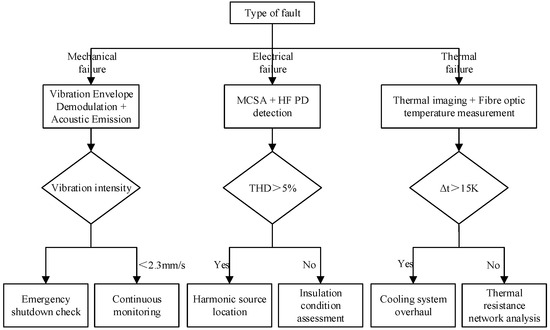
Figure 1.
Decision tree for selection of fault detection methods for shipboard motors.
Mechanical faults are detected by vibration envelope demodulation and acoustic emission technology. Afterwards, the vibration speed is judged; if the vibration speed is less than 2.3 m/s, a liquid-colored shutdown inspection is carried out; if it is not less than that, a bearing inspection is carried out. Electrical faults include MCSA with high-frequency PD (partial discharge) detection. It is determined whether the total harmonic distortion (THD) is greater than 5%; if it is greater, the harmonic source is located; if not, the insulation condition is assessed. Thermal faults use infrared thermal imaging and fiber optic temperature measurement. It is determined whether the temperature difference (Δt) is greater than 15 K; if greater, a cooling system overhaul is carried out; if not, thermal resistance network analysis is carried out.
Table 10 represents a table of comparative analyses of a ship’s special needs. As shown in Table 10, different environmental interference factors significantly affect monitoring methods. Among them, electromagnetic interference has the most severe impact on MCSA and high-frequency partial discharge detection. By adopting fiber optic current sensors, the signal-to-noise ratio was effectively improved by 26 dB, demonstrating a substantial enhancement in anti-interference capability. To address false alarms caused by hull vibration, an IMU-based compensation algorithm was introduced, resulting in a 68% reduction in false alarm rate. In addition, under conditions of salt fog corrosion and spatial constraints, the use of corrosion-resistant infrared windows and miniature TMR magnetic sensor arrays respectively optimized transmittance and volumetric performance.
Table 10.
Comparative analysis table of special needs of ships.
In summary, typical faults in shipboard motors do not originate from a single physical field but rather reflect the highly coupled interactions and feedback among multiple physical domains, including electrical, thermal, mechanical, and magnetic fields. This study incorporates a multi-physics coupling perspective across various stages, such as mechanism modeling, feature extraction, and fusion-based decision making, thereby enhancing the engineering applicability and interpretability of the diagnostic model.
3. Key Technology for Shipboard Motor Fault Monitoring
Although Section 2 establishes detailed physical models based on typical fault mechanisms and extracts key feature signals, in practical shipboard applications, solely relying on physics-based modeling presents certain limitations in terms of adaptability and real-time performance under complex operating conditions and multi-source disturbances. For instance, difficulties in real-time acquisition of model parameters or their temporal drift, as well as intensified signal noise caused by severe electromagnetic fluctuations, may all degrade diagnostic accuracy. Therefore, the model-driven and data-driven methods introduced in Section 3 are not intended to replace or negate the approaches in Section 2, but rather to serve as a valuable complement. On one hand, model-driven methods offer accurate and interpretable estimations in scenarios with well-understood mechanisms, thereby enhancing physical consistency. On the other hand, data-driven methods demonstrate strong adaptability and robustness, making them suitable for handling high-dimensional, nonlinear signals in disturbed environments. The synergistic development of both approaches can more comprehensively address the challenges of fault monitoring under complex conditions in shipboard motors, thus improving the system’s intelligence and robustness.
Ship motor systems operate in extreme environments, such as high salt spray, high humidity and heat, and traditional monitoring methods and emerging intelligent diagnostic techniques face many challenges in this field [30]. In this chapter, the current key technology paths for fault monitoring of ship motors and their engineering adaptability are systematically sorted out from the three dimensions of model-driven methods, data-driven methods and edge computing platforms.
3.1. Model-Driven Approach
The model-driven approach relies on mathematical modeling of the system by constructing a mathematical model of the motor, combining methods such as observers and filters to estimate key motor variables and enable fault monitoring [31,32,33]. Its advantage lies in its strong interpretability and deep insight into the internal states of complex systems, making it suitable for scenarios where clear mechanism knowledge is available or accurate model parameters can be obtained. For example, the use of a Luenberger observer to estimate rotor position deviation and trigger instability warnings by setting a threshold Δθ can effectively meet the high-precision control requirements of propulsion systems. This is achieved through the calculation in Equation (1).
where denotes the state estimation vector, u is the control input, and y represents the system output. A, B, and C are the state-space model matrices of the system; L is the observer gain matrix; is the estimated rotor position angle; and is the rotor position angle measured by the encoder. The instability warning is triggered when Δθ > 0.1°. To address the complex load perturbations in the naval environment, the researchers propose the following relevant solutions: (1) introducing an adaptive gain adjustment mechanism to enhance the model’s response to transient shocks (e.g., full-speed reversing conditions) [34]; and (2) fusing with the mechanical vibration signals to enhance their physical consistency and interpretability [35].
However, this method relies heavily on modeling accuracy and exhibits limited robustness and generalization capability in shipboard environments characterized by strong nonlinearity and varying operating conditions. Therefore, it is often used as a high-precision analysis tool or in combination with data-driven models in practical applications. In engineering practice, in the stator short-circuit diagnosis of a certain type of naval propulsion motor, the simulated and measured axial leakage flux waveform similarity (cosine similarity > 0.92) is compared to locate the fault phase, with an accuracy rate of 89.7% [36].
3.2. Data-Driven Approach
In recent years, with the improvement of the accuracy of shipboard sensors and embedded computing power, data-driven methods have gradually become the mainstream means of fault monitoring for shipboard motors. Data-driven methods identify potential fault features by training and learning from historical or real-time collected data. These methods do not rely on motor structure modeling and exhibit strong nonlinear fitting capabilities and engineering scalability, making them particularly suitable for complex scenarios characterized by strong electromagnetic interference and non-stationary operating conditions [37,38,39,40]. Among such methods, the vibration timing processing framework based on a one-dimensional convolutional neural network (1D-CNN) has received widespread attention due to its lightweight structure and strong timing modeling capability.
In the context of strong interference in ships, 1D-CNN is often combined with adaptive frequency-domain filtering and time-domain attention mechanisms to achieve signal enhancement. First, the passband center frequency fc and bandwidth Δf are dynamically adjusted by introducing a learnable bandpass filter, so that it automatically adapts to the frequency characteristics of different fault signals. For example, the typical bandwidth Δf of a bearing fault is about 200 Hz, and the filter can be expanded by a factor of 1.5 to balance the frequency resolution and noise immunity. Compared with conventional fixed-parameter filters, this structure shows better robustness in the naval environment where the rotational speed changes drastically or the operating conditions switch frequently (shown in Table 11).
Table 11.
Learnable bandpass filters vs. conventional filters.
Secondly, related studies have shown that the network structure adopts residual connectivity and inflationary convolution to expand the receptive field and extract multi-scale features, and combines the Attention mechanism to dynamically weight the temporal segments to enhance the detection sensitivity of shock-type micro-faults (e.g., spalled bearings, rotor knocking).Experiments show that the structure can significantly suppress the transient disturbances introduced by diesel engine start/stop and power switching when identifying typical shipboard fault signals.
To further improve the anti-disturbance performance of the model, some study introduces an adversarial training strategy to construct adversarial samples under simulated disturbances and introduce them into the training process. The method constructs input samples x′ under slight disturbances by controlling the disturbance amplitude ϵ (the recommended value for ships is 0.05) and incorporates them into the loss function to improve the robustness and generalization ability of the model. In the engineering deployment, a certain type of ship propulsion motor still maintains a classification accuracy of 92.3% under the working condition where the signal-to-noise ratio is reduced to −5 dB, which is much better than that of the traditional envelope spectral demodulation method (67.5%).
Overall, the advantages of the data-driven approach in fault monitoring of ship motors are mainly reflected in two points: (1) adapting to the strong electromagnetic interference and non-steady vibration environment; (2) supporting lightweight hardware deployment. Future research can further explore its generalization performance optimization in small sample scenarios, its fusion approach with physical modeling, and its joint modeling capability for multimodal data (e.g., current, temperature).
Nevertheless, data-driven methods still face several challenges, including a strong dependence on labeled data, limited generalization ability under small-sample conditions, and the high computational burden of deploying deep models on shipboard platforms. Consequently, strategies such as adversarial training and transfer learning have been introduced in recent years to enhance model robustness. In the future, it is also necessary to further strengthen the integration of these methods with physical models to improve engineering interpretability.
3.3. Edge Computing and Embedded Systems
Shipboard motor fault monitoring is gradually evolving from centralized offline processing to edge-intelligent diagnostic systems, where the monitoring architecture must meet requirements for high real-time performance, strong environmental adaptability, and low power consumption [41,42]. Against this background, this paper further analyzes the applicability boundaries, engineering deployment characteristics, and existing limitations of current intelligent diagnostic methods to enhance their guidance for practical engineering applications.
3.3.1. Lightweight Fault Detection Platform
To meet the demands of naval vessels for highly integrated and low-power edge processing units, the lightweight embedded platform based on the STM32H7 series has become an ideal choice. Table 12 compares the performance of STM32H743 and NI Compact RIO in terms of key technical indicators.
Table 12.
Typical Configuration performance comparison.
The results indicate that the STM32H743 can achieve over 90% of the real-time performance of NI devices while consuming only one-sixth of the power, and offers superior environmental adaptability, making it a preferred platform for edge deployment of fault monitoring systems in shipboard environments. However, the STM32 is limited by memory and computational capacity when processing complex deep neural network models, and its applicability still relies on model compression and edge inference optimization techniques, such as quantization and pruning.
3.3.2. Smart Sensor Network Construction
The intelligent sensor network architecture based on the IEEE 1451 standard [43] (as shown in Figure 2) enables plug-and-play functionality and automatic metadata recognition through modular design and the transducer electronic data sheet (TEDS) mechanism. It can also embed health indicators, such as triggering maintenance alarms when the vibration signal-to-noise ratio decreases by more than 3 dB. This system features strong scalability and self-diagnosis capabilities, making it suitable for large-scale deployment networks targeting shipboard motors.
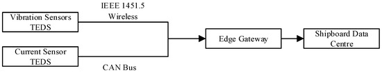
Figure 2.
Smart sensor network architecture diagram.
The intelligent sensor network provides critical support for realizing full lifecycle health monitoring of shipboard systems. When integrated with edge platforms, it can significantly reduce data transmission pressure and shorten response time. However, this system also faces risks of false alarms and missed detections in cases of sensor failures or data anomalies, placing higher demands on the robustness and redundancy strategies of embedded diagnostic algorithms.
Overall, the integration of lightweight embedded platforms, deep learning models, and standardized intelligent sensing networks is driving shipboard motor monitoring systems from centralized diagnosis toward distributed intelligent collaboration. This evolution is expected to substantially enhance the adaptability, response efficiency, and intelligent maintenance level of ship integrated support systems. Future research should focus on key technical paths, such as edge AI model compression, robust multi-sensor fusion modeling, and secure remote upgrade mechanisms.
4. Analysis of Technical Challenges in the Special Environment of Ships
4.1. Electromagnetic Compatibility Issues
Ship platforms are densely equipped and highly integrated with electronic systems, placing motor monitoring systems in environments with strong electromagnetic interference. Common sources of interference include radar pulses (2–18 GHz band), transient currents from weapon systems (peak > 10 kA), and high-frequency common-mode noise generated by inverters (dv/dt > 10 kV/μs). These interferences can cause a sudden drop in the signal-to-noise ratio of sensor outputs by more than 40 dB. In such environments, traditional Hall current sensors may exhibit measurement errors of up to 15% under PWM excitation. To address this problem, three main solution strategies have been proposed:
(1) Fiber-optic current sensor based on Faraday magneto–optical effect, which is completely immune to electromagnetic interference and can still maintain ±0.2% measurement accuracy in strong radar radiation environments (25 times higher than Hall elements).
(2) The triple-shielded cable design consisting of copper mesh (<1 Ω/sq), aluminium foil (>100 dB attenuation) and ferrite magnetic ring can achieve common mode noise suppression of more than 60 dB.
(3) Adaptive filtering algorithm with real-time spectrum analysis (Fast Fourier Transform (FFT) update rate > 1 kHz) achieves 45 dB active trap suppression for key interference bands, such as L-band radar (1.2 GHz).
Together, these technologies constitute the electromagnetic protection system of the ship’s motor monitoring system.
4.2. Reliability Verification Criteria
Reliability verification of shipboard motors is subject to stringent standards, but there are particular challenges. Accelerated life testing (ALT) has significant limitations in the reliability assessment of shipboard motors. Firstly, high temperature acceleration (Arrhenius model) may lead to unrealistic failures, such as embrittlement of insulation materials (T > 130 °C), resulting in 35% deviation of the predicted life of a certain type of motor from the actual at-sea data of ALT. Secondly, ALT usually adopts a single stress acceleration, while the real environment of the ship is a multi-stress coupling of vibration, salt spray, temperature and electromagnetism, for example, salt spray corrosion will change the lubrication characteristics of the bearings, thus affecting the evolution path of vibration failures, and this composite effect is difficult to be accurately simulated by the traditional ALT. Table 13 compares the main criteria for testing.
Table 13.
Comparative analysis of test standards.
Aiming to bridge the difference between accelerated testing and actual service environment, some study proposes a hybrid prediction model combining ALT results and shipboard measured data with the following modified life expression:
where kenv indicates the environmental correction factor (e.g., about 0.2 in the South China Sea area, and up to 0.6 in the mild area), and Lreal indicates the actual sea service life (hours); and LALT indicates the predicted life (hours) of the accelerated test. The formula quantifies the difference between the accelerated test and the real environment, and has been verified by 120,000 h of service data of a certain type of ship’s motor (goodness of fit R2 = 0.87).
Meanwhile, an intelligent monitoring system is deployed to dynamically adjust the failure threshold by collecting environmental stress data, such as salt spray concentration and vibration spectrum, in real time through a fiber-optic sensing network. In addition, a multi-stress coupling accelerated test device needs to be developed to simulate the composite working conditions of vibration + salt spray + temperature + electromagnetism to more realistically reflect the actual failure mechanism.
5. Future Research Directions
Building upon current research, future studies on shipboard motor fault monitoring should focus on overcoming key technical bottlenecks and clarifying practical engineering implementation pathways. Specifically, research efforts may advance in three main directions: digital twin modeling, autonomous health management, and novel sensing technologies. It is important to emphasize that although numerous emerging technological approaches exist, they will be of limited effectiveness if detached from the feasibility and engineering constraints of shipboard environments. Therefore, future research should not only pursue theoretical innovation at the frontier but also remain closely aligned with the complex operating conditions and service demands of naval power systems, thereby promoting the transition from laboratory research to real-ship deployment.
5.1. Digital Twin
The core of digital twin technology for shipboard motors lies in constructing a high-fidelity coupled model of the motor–grid–load system, which requires overcoming key challenges in multi-scale modeling and real-time data fusion [45,46,47]. The current technical bottlenecks mainly include the difficulty of balancing accuracy and real-time performance in multi-physics modeling, the lack of a robust mechanism for model parameter updates, and computational constraints in spatiotemporal alignment and high-frequency updating of heterogeneous data.
Future research should advance collaboratively from both modeling and data fusion perspectives. At the modeling level, it is necessary to combine electromagnetic field finite element simulation (e.g., ANSYS Maxwell simulation of stator-rotor eccentricity and permanent magnet demagnetization), CFD analysis, and multi-body dynamics and vibration simulation (0.1–10 kHz bearing impact response analysis) to achieve high-fidelity modeling of multi-physical fields. Synchronization of multi-source heterogeneous sensor data through the shipboard 5G network allows real-time updating of the digital twin parameters, keeping the RUL prediction error within 5%. Relevant engineering practices have preliminarily verified their value, e.g., the digital twin of an aircraft carrier’s power system has achieved online optimization of motor efficiency (2.3% improvement) and 10 ms-level fast localization of short-circuit faults, which verifies the engineering value of this technology in shipboard power systems [48].
However, the deployment of digital twin technology in shipboard scenarios still faces several challenges: (1) high modeling complexity and difficulties in engineering implementation; (2) limited edge computing resources, which constrain high-frequency model synchronization; and (3) sensor drift and noise interference, which introduce disturbances to the real-time updating of the twin model. Therefore, it is necessary to develop lightweight digital twin frameworks, incremental learning mechanisms for edge deployment, and multi-model collaborative fusion strategies.
5.2. Self-Directed Health Management
Shipboard systems commonly face challenges such as information silos and data security constraints. Traditional centralized fault diagnosis architectures exhibit significant limitations in fleet-level collaborative maintenance and fail to meet the requirements of distributed, highly confidential, and real-time operational support. Future research direction focuses on federated learning (FL)-driven [49] distributed prognostics and health management (PHM) systems [4,50,51,52], whose key research points include: (1) privacy protection and model sharing; (2) dynamic knowledge base construction; and (3) fleet-level collaborative optimization mechanism.
The core of achieving fleet-level collaborative diagnosis based on federated learning technology lies in knowledge sharing and dynamic knowledge base construction under privacy protection [53,54,55]. Each ship trains the fault diagnosis model locally, uploads only the model gradient (not the raw data), and uses homomorphic encryption to ensure transmission security (which increases the computational overhead). The system constructs a dynamically updated fault knowledge base by mining common features across ships (e.g., salt spray corrosion patterns of propulsion motor bearings), and applies weight decay to older ship data to optimize model timeliness. The technology has demonstrated significant military benefits, enabling improved fault diagnosis accuracy for new ship motors through historical fleet data sharing, while meeting information security requirements. This distributed intelligent operation and maintenance model not only guarantees the independence of each ship’s data but also realizes a leap in the overall maintenance level of the fleet, providing an innovative solution for the whole life cycle management of naval equipment.
5.3. New Sensor Technology
As the data acquisition front-end of fault monitoring systems, the performance of sensors directly determines the monitoring accuracy and reliability of the entire system. In the complex shipboard environment—characterized by high salinity, humidity, vibration, and strong electromagnetic interference—conventional electronic sensors often experience performance drift and reduced reliability during long-term service. Fiber Bragg grating (FBG)-based sensor technology is becoming a revolutionary solution for shipboard motor monitoring, and its core advantage lies in the integrated integration of multiple parameters and extreme environmental adaptability [56,57,58]. A single optical fiber can achieve simultaneous monitoring of multiple physical quantities, such as temperature, vibration and current, and immunity to electromagnetic interference through wavelength demodulation, with a weight reduction of more than 70% compared to traditional sensors. FBG can be directly embedded in key parts of the motor (e.g., bearing seats, winding ends), and has a life span of more than 15 years of resistance to salt spray and corrosion, which is significantly better than that of electronic sensors. However, FBG sensors still face cross-sensitivity issues in shipboard applications, particularly the decline in signal demodulation accuracy under coupled temperature-strain fields. To enable engineering deployment, future work should focus on developing strain decoupling algorithms based on dual-parameter or multi-grating structures, combined with adaptive filtering and model calibration mechanisms to enhance signal reliability in dynamic environments. Moreover, exploring integration with wireless fiber-optic transmission technologies could facilitate the realization of a fully passive onboard sensing network, thereby advancing the overall upgrade of shipboard health monitoring systems.
6. Conclusions and Recommendations
This paper systematically reviews recent advancements in fault monitoring and health management technologies for shipboard motors. It focuses on multi-physics modeling methods for typical faults, such as bearing electrical erosion, rotor eccentricity, and permanent magnet demagnetization. The paper also summarizes multi-source signal feature extraction techniques involving current, vibration, and temperature signals, and proposes a distributed intelligent diagnosis strategy integrating deep learning and federated learning. Based on this, an intelligent health management architecture is constructed across unit-level, system-level, and fleet-level hierarchies, with key technologies validated through representative engineering application cases. The results indicate that intelligent fault identification schemes based on digital twins and multimodal signal fusion can achieve diagnostic accuracy exceeding 95% with strong robustness to high noise. Through multi-source heterogeneous modeling and system-level collaborative analysis, precise localization and root cause tracking of complex faults can be achieved. Moreover, with federated learning and knowledge-sharing mechanisms, fleet-level collaborative diagnosis models can significantly improve generalization capabilities while ensuring information security.
While promoting technological development, it is urgent to improve the supporting policy framework. First, key health indicators of electric motors—such as vibration characteristic frequencies and insulation degradation indices—should be mandated for transmission via the long-range identification and tracking system, in line with the IMO MSC.1/Circ.1580 standardized data interface. Second, leveraging national intelligent ship innovation centers and naval equipment research institutes, a shipboard motor health database should be established to enable secure sharing of commercial vessel data and enhance model generalization. Finally, it is recommended to introduce targeted incentive policies, such as tax reductions for enterprises applying intelligent sensing systems and dedicated funding programs to support independent R\&D in critical areas, thereby promoting coordinated advancement of technology and policy for the development of intelligent maintenance systems.
Author Contributions
Conceptualization, J.S., P.S., B.L. and W.L.; methodology, J.S. and W.L.; formal analysis, P.S. and B.L.; investigation, J.S., P.S., B.L. and W.L.; writing—original draft preparation, J.S. and W.L.; writing—review and editing, P.S. and B.L.; supervision, P.S. and W.L.; funding acquisition, W.L. All authors have read and agreed to the published version of the manuscript.
Funding
This research was funded by the Department of Science and Technology of Hubei Province (2024BAB067).
Conflicts of Interest
The authors declare no conflict of interest.
References
- IEEE. IEEE Standard Test Procedure for Polyphase Induction Motors and Generators; IEEE: Piscataway, NJ, USA, 2018. [Google Scholar] [CrossRef]
- The Three Departments Jointly Issued the Action Plan for the Development of Intelligent Ships (2019–2021). Available online: https://www.gov.cn/xinwen/2018-12/30/content_5353550.htm (accessed on 18 April 2025).
- Vrijdag, A.; Martelli, M. Parameter Identification of a Model Scale Ship Drive Train. J. Mar. Sci. Eng. 2021, 9, 268. [Google Scholar] [CrossRef]
- Aizpurua, J.I.; Knutsen, K.E.; Heimdal, M.; Vanem, E. Integrated Machine Learning and Probabilistic Degradation Approach for Vessel Electric Motor Prognostics. Ocean Eng. 2023, 275, 114153. [Google Scholar] [CrossRef]
- Zhang, P.; Gao, Z.; Cao, L.; Dong, F.; Zou, Y.; Wang, K.; Zhang, Y.; Sun, P. Marine Systems and Equipment Prognostics and Health Management: A Systematic Review from Health Condition Monitoring to Maintenance Strategy. Machines 2022, 10, 72. [Google Scholar] [CrossRef]
- Zamudio-Ramirez, I.; Osornio-Rios, R.A.; Antonino-Daviu, J.A.; Razik, H.; Romero-Troncoso, R. Magnetic Flux Analysis for the Condition Monitoring of Electric Machines: A Review. IEEE Trans. Ind. Inform. 2022, 18, 2895–2908. [Google Scholar] [CrossRef]
- Jaros, R.; Byrtus, R.; Dohnal, J.; Danys, L.; Baros, J.; Koziorek, J.; Zmij, P.; Martinek, R. Advanced Signal Processing Methods for Condition Monitoring. Arch. Comput. Methods Eng. 2023, 30, 1553–1577. [Google Scholar] [CrossRef]
- Akbar, S.; Vaimann, T.; Asad, B.; Kallaste, A.; Sardar, M.U.; Kudelina, K. State-of-the-Art Techniques for Fault Diagnosis in Electrical Machines: Advancements and Future Directions. Energies 2023, 16, 6345. [Google Scholar] [CrossRef]
- Kudelina, K.; Vaimann, T.; Asad, B.; Rassõlkin, A.; Kallaste, A.; Demidova, G. Trends and Challenges in Intelligent Condition Monitoring of Electrical Machines Using Machine Learning. Appl. Sci. 2021, 11, 2761. [Google Scholar] [CrossRef]
- Kudelina, K.; Asad, B.; Vaimann, T.; Rassõlkin, A.; Kallaste, A.; Khang, H.V. Methods of Condition Monitoring and Fault Detection for Electrical Machines. Energies 2021, 14, 7459. [Google Scholar] [CrossRef]
- Shang, L.; Niu, Y.; Mao, L.; Niu, H. Selection and Application of Vibration Acceptance Standards for Centrifugal Pumps GB/T 29531-2013 and ISO 10816-7. Pump Technol. 2017, 3, 26–28+33. [Google Scholar]
- Kumar, R.R.; Andriollo, M.; Cirrincione, G.; Cirrincione, M.; Tortella, A. A Comprehensive Review of Conventional and Intelligence-Based Approaches for the Fault Diagnosis and Condition Monitoring of Induction Motors. Energies 2022, 15, 8938. [Google Scholar] [CrossRef]
- Mazaheri-Tehrani, E.; Faiz, J. Airgap and Stray Magnetic Flux Monitoring Techniques for Fault Diagnosis of Electrical Machines: An Overview. IET Electr. Power Appl. 2022, 16, 277–299. [Google Scholar] [CrossRef]
- MSC.1/Circular.1580—Guidelines for Vessels and Units with Dynamic Positioning (DP) Systems. Available online: https://imorules.com/MSCCIRC_1580.html (accessed on 18 April 2025).
- Long-Range Identification and Tracking (LRIT). Available online: https://www.imo.org/en/OurWork/Safety/Pages/LRIT.aspx (accessed on 18 April 2025).
- Abad, H.B.B.; Ojaghi, M.; Taheri, A. Extra Freedom Degrees of Six-Phase Induction Motors Used to Diagnose Stator Inter-Turn Faults. Electr. Power Compon. Syst. 2021, 49, 294–307. [Google Scholar] [CrossRef]
- Abbasi, M.A.; Huang, S.; Khan, A.S. Fault Detection and Classification of Motor Bearings under Multiple Operating Conditions. ISA Trans. 2025, 156, 61–69. [Google Scholar] [CrossRef] [PubMed]
- Song, M.; Yan, P.; Wang, X.; Yang, Y.; Xie, R. Exploration of maximum unbalance of a turboshaft engine according to airworthiness requirements. J. Aerosp. Power 2023, 38, 1467–1473. [Google Scholar]
- Li, J.; Li, Z.; Zhang, J.; Zhao, S.; Cheng, F.; Qian, C.; Hu, X.; Zhou, G. Automated Monitoring of the Uniform Demagnetization Faults in Permanent-Magnet Synchronous Motors: Practical Methods and Challenges. Sustainability 2023, 15, 16326. [Google Scholar] [CrossRef]
- Du, Z.; Huang, Y.; Zhang, Z.; Wu, L.; Su, W.; Li, W. Method of Maintenance Cycle Prediction for Smart Electricity Meters Based on Hybrid Weibull Distribution. Electr. Meas. Instrum. Chin. 2025, 62, 217–224. [Google Scholar]
- Song, X.; Liao, Z.; Jia, B. Marine Fire Pump Motor Bearings Fault Feature Enhancement and Diagnosis Based on Adaptive SSA and Improved TEO. Chin. J. Ship Res. 2025, 20, 47–55. [Google Scholar]
- Ge, C.; Yan, Z.; Shang, J.; Xue, H. Fault Diagnosis of Ship Motor Bearings Based on Multi-Domain Information Fusion and Improved ELM. Chin. J. Ship Res. 2025, 20, 68–76. [Google Scholar]
- Zhu, R.; Song, E.; Yao, C.; Ke, Y. Marine Motor Fault Diagnosis Based on CEEMDAN and BRECANunder Strong Noise Conditions. Chin. J. Ship Res. 2025, 20, 20–29. [Google Scholar]
- Zhang, Z. Research on Diagnosis Technology Based on Typical Fault of Marine Generator. Master’s Thesis, Harbin Engineering University, Harbin, China, 2025. [Google Scholar]
- Fu, C.; Shi, W. Intelligent Fault Diagnosis of Marine Generator Stator Windings Combined with Attention Mechanism. Control Eng. China 2025, in press. [Google Scholar]
- Jang, J.-G.; Noh, C.-M.; Kim, S.-S.; Shin, S.-C.; Lee, S.-S.; Lee, J.-C. Vibration Data Feature Extraction and Deep Learning-Based Preprocessing Method for Highly Accurate Motor Fault Diagnosis. J. Comput. Des. Eng. 2023, 10, 204–220. [Google Scholar] [CrossRef]
- Shu, R.; Wei, J.; Tan, R.; Wu, X.; Fu, B. Investigation of Dynamic and Synchronization Properties of a Multi-Motor Driving System: Theoretical Analysis and Experiment. Mech. Syst. Signal Process. 2021, 153, 107496. [Google Scholar] [CrossRef]
- Feldman, M. Hilbert Transform in Vibration Analysis. Mech. Syst. Signal Process. 2011, 25, 735–802. [Google Scholar] [CrossRef]
- Xu, X.; Huang, W.; Zhang, X.; Zhang, Z.; Liu, F.; Brunauer, G. An Evidential Reasoning-Based Information Fusion Method for Fault Diagnosis of Ship Rudder. Ocean Eng. 2025, 318, 120082. [Google Scholar] [CrossRef]
- Nesser, H.; Mahmoud, H.A.; Lubineau, G. High-Sensitivity RFID Sensor for Structural Health Monitoring. Adv. Sci. 2023, 10, 2301807. [Google Scholar] [CrossRef] [PubMed]
- Kim, J.; Song, M.; Kim, D.; Lee, D. An Adaptive Kalman Filter-Based Condition-Monitoring Technique for Induction Motors. IEEE Access 2023, 11, 46373–46381. [Google Scholar] [CrossRef]
- Sardar, M.U.; Vaimann, T.; Kütt, L.; Kallaste, A.; Asad, B.; Akbar, S.; Kudelina, K. Inverter-Fed Motor Drive System: A Systematic Analysis of Condition Monitoring and Practical Diagnostic Techniques. Energies 2023, 16, 5628. [Google Scholar] [CrossRef]
- Huang, K.; Li, W.; Fang, H.; Wu, X.; Wang, L.; Peng, H. IPORF: A Combined Improved Parrot Optimizer Algorithm and Random Forest for Fault Diagnosis in AUV. Ocean Eng. 2024, 313, 119665. [Google Scholar] [CrossRef]
- Ma, C.; He, X.; Xie, B.; Sun, W.; Zhao, D.; Liao, W. Backstepping Sliding Mode Fault-Tolerant Control for the Wind Turbine System with Disturbance Observer. Proc. Inst. Mech. Eng. Part J. Syst. Control Eng. 2022, 236, 1667–1678. [Google Scholar] [CrossRef]
- Hou, Y.; Wang, J.; Chen, Z.; Ma, J.; Li, T. Diagnosisformer: An Efficient Rolling Bearing Fault Diagnosis Method Based on Improved Transformer. Eng. Appl. Artif. Intell. 2023, 124, 106507. [Google Scholar] [CrossRef]
- Cureño-Osornio, J.; Díaz-Saldaña, G.; Osornio-Rios, R.A.; Dunai, L.; Sava, L.; Antonino-Daviu, J.A.; Zamudio-Ramírez, I. Detection of Contamination and Failure in the Outer Race on Ceramic, Metallic, and Hybrid Bearings through AI Using Magnetic Flux and Current. Machines 2024, 12, 505. [Google Scholar] [CrossRef]
- Huang, K.; Li, W.; Gao, F. Barabási-Albert Model-Enhanced Genetic Algorithm for Optimizing LGBM in Ship Power Grid Fault Diagnosis. Measurement 2025, 249, 116954. [Google Scholar] [CrossRef]
- Guo, Q.; Li, Y.; Song, Y.; Wang, D.; Chen, W. Intelligent Fault Diagnosis Method Based on Full 1-D Convolutional Generative Adversarial Network. IEEE Trans. Ind. Inform. 2020, 16, 2044–2053. [Google Scholar] [CrossRef]
- Guo, Y.; Gao, C.; Jin, Y.; Li, Y.; Wang, J.; Li, Q.; Wang, H. A Transfer Learning-Based Method for Marine Machinery Diagnosis with Small Samples in Noisy Environments. J. Ocean Eng. Sci. 2023, 10, 593–601. [Google Scholar] [CrossRef]
- Xie, F.; Li, G.; Hu, W.; Fan, Q.; Zhou, S. Intelligent Fault Diagnosis of Variable-Condition Motors Using a Dual-Mode Fusion Attention Residual. J. Mar. Sci. Eng. 2023, 11, 1385. [Google Scholar] [CrossRef]
- Ayyappan, G.S.; Ramesh Babu, B.; Srinivas, K.; Raja Raghavan, M.; Poonthalir, R. Mathematical Modelling and IoT Enabled Instrumentation for Simulation & Emulation of Induction Motor Faults. IETE J. Res. 2023, 69, 1829–1841. [Google Scholar] [CrossRef]
- Yao, Z.; Zhu, Q.; Zhang, Y.; Huang, H.; Luo, M. Minimizing Long-Term Energy Consumption in RIS-Assisted AAV-Enabled MEC Network. IEEE Internet Things J. 2025, 12, 20942–20958. [Google Scholar] [CrossRef]
- Chen, W.; Zhang, Z.; Li, J.; Wei, C.; Chen, Q. Intelligent Sensing Technology for Power Equipment State Parameters. Proc. CSEE 2020, 20, 323–342. [Google Scholar]
- Ge, Y.; Lei, X.; Zhang, Y.; Fang, Z.; Lu, Z. Analysis and Test on Permissible Residual Unbalance of Rotors. J. Vib. Meas. Diagn. 2023, 43, 371–377+414–415. [Google Scholar]
- Tao, F.; Qi, Q.; Wang, L.; Nee, A.Y.C. Digital Twins and Cyber–Physical Systems toward Smart Manufacturing and Industry 4.0: Correlation and Comparison. Engineering 2019, 5, 653–661. [Google Scholar] [CrossRef]
- Fera, F.; Spandonidis, C. A Fault Diagnosis Approach Utilizing Artificial Intelligence for Maritime Power Systems within an Integrated Digital Twin Framework. Appl. Sci. 2024, 14, 8107. [Google Scholar] [CrossRef]
- Hu, W.; Wang, T.; Chu, F. Novel Ramanujan Digital Twin for Motor Periodic Fault Monitoring and Detection. IEEE Trans. Ind. Inform. 2023, 19, 11564–11572. [Google Scholar] [CrossRef]
- Zhang, Q.; Song, H.; Li, L.; Song, Z.; Li, Z. Marine Power System Intelligent Operation and Maintenance Platform Based on Digital Twin. Chin. J. Ship Res. 2022, 17, 73–80. [Google Scholar]
- Yang, Q.; Liu, Y.; Chen, T.; Tong, Y. Federated Machine Learning: Concept and Applications. ACM Trans. Intell. Syst. Technol. 2019, 10, 1–19. [Google Scholar] [CrossRef]
- Huang, C.; Bu, S.; Lee, H.H.; Chan, K.W.; Yung, W.K.C. Prognostics and Health Management for Induction Machines: A Comprehensive Review. J. Intell. Manuf. 2024, 35, 937–962. [Google Scholar] [CrossRef]
- Yang, F.; Habibullah, M.S.; Shen, Y. Remaining Useful Life Prediction of Induction Motors Using Nonlinear Degradation of Health Index. Mech. Syst. Signal Process. 2021, 148, 107183. [Google Scholar] [CrossRef]
- Kim, S.; Kim, N.H.; Choi, J.-H. A Study Toward Appropriate Architecture of System-Level Prognostics: Physics-Based and Data-Driven Approaches. IEEE Access 2021, 9, 157960–157972. [Google Scholar] [CrossRef]
- Russell, M.; Wang, P. Maximizing Model Generalization for Machine Condition Monitoring with Self-Supervised Learning and Federated Learning. J. Manuf. Syst. 2023, 71, 274–285. [Google Scholar] [CrossRef]
- Zhang, Z.; Zhou, F.; Zhang, C.; Wen, C.; Hu, X.; Wang, T. A Personalized Federated Learning-Based Fault Diagnosis Method for Data Suffering from Network Attacks. Appl. Intell. 2023, 53, 22834–22849. [Google Scholar] [CrossRef]
- Jenkel, L.; Jonas, S.; Meyer, A. Privacy-Preserving Fleet-Wide Learning of Wind Turbine Conditions with Federated Learning. Energies 2023, 16, 6377. [Google Scholar] [CrossRef]
- Chan, T.H.T.; Yu, L.; Tam, H.Y.; Ni, Y.Q.; Liu, S.Y.; Chung, W.H.; Cheng, L.K. Fiber Bragg Grating Sensors for Structural Health Monitoring of Tsing Ma Bridge: Background and Experimental Observation. Eng. Struct. 2006, 28, 648–659. [Google Scholar] [CrossRef]
- Kumar, P.; Yao, C.-K.; Augustine Arockiyadoss, M.; Mulatie Dehnaw, A.; Chang, C.-Y.; Peng, P.-C. YOLO-v7 Improved with Adan Optimizer: Realizing Orphaned Fiber Bragg Grating to Sense Superimposed Personalized Dynamic Strain. IEEE Sens. J. 2024, 24, 39923–39933. [Google Scholar] [CrossRef]
- Vaddadi, V.S.C.S.; Parne, S.R.; Parambil, V.V.; Panda, S.S.S.; Gandi, S. Design of Fiber Bragg Grating Sensor for Eccentricity Measurements in Ball Bearings. IEEE Trans. Instrum. Meas. 2023, 72, 7000309. [Google Scholar] [CrossRef]
Disclaimer/Publisher’s Note: The statements, opinions and data contained in all publications are solely those of the individual author(s) and contributor(s) and not of MDPI and/or the editor(s). MDPI and/or the editor(s) disclaim responsibility for any injury to people or property resulting from any ideas, methods, instructions or products referred to in the content. |
© 2025 by the authors. Licensee MDPI, Basel, Switzerland. This article is an open access article distributed under the terms and conditions of the Creative Commons Attribution (CC BY) license (https://creativecommons.org/licenses/by/4.0/).